40
Innovative supplier of inductive components

Innovative supplier of inductive components

2

3
General Notes: Most ETAL components are compliant with RoHS Directive 2002/95/EC, and are suitable for
Pb-free and conventional placement and re"ow. Dimensions shown are in millimetres.
This catalogue is intended to be a general guide of our products, for speci#c technical speci#cations please
refer to the individual datasheets.
ETAL operate a policy of continuous improvement and although every care has been taken to ensure the
details in this catalogue were correct at the time of print, please appreciate that we must reserve the right to
alter details or speci#cations at any time.
No part of this catalogue may be reproduced, reprinted or translated without written permission
from ETAL Group.
Table of contents
Table of contents . . . . . . . . . . . . . . . . . . . . . . . . . . . . . . . . . . . . . . . . . . . . . . . . . . . . . . . . . . . . . . . . . . . . . . . . . . . . . . . . . . . . . . . . . . . 3
Company information . . . . . . . . . . . . . . . . . . . . . . . . . . . . . . . . . . . . . . . . . . . . . . . . . . . . . . . . . . . . . . . . . . . . . . . . . . . . . . . . . . . 4-5
Customized products . . . . . . . . . . . . . . . . . . . . . . . . . . . . . . . . . . . . . . . . . . . . . . . . . . . . . . . . . . . . . . . . . . . . . . . . . . . . . . . . . . . . . 6-8
Standard products
Line Transformers . . . . . . . . . . . . . . . . . . . . . . . . . . . . . . . . . . . . . . . . . . . . . . . . . . . . . . . . . . . . . . . . . . . . . . . . . 9
High Impedance “Pick off” transformers . . . . . . . . . . . . . . . . . . . . . . . . . . . . . . . . . . . . . . . 10
Planar Power Transformers . . . . . . . . . . . . . . . . . . . . . . . . . . . . . . . . . . . . . . . . . . . . . . . . . . . . . . . . . . . 10
xDSL Products . . . . . . . . . . . . . . . . . . . . . . . . . . . . . . . . . . . . . . . . . . . . . . . . . . . . . . . . . . . . . . . . . . . . . . . . . . . 11
Powerline Carrier Isolation Transformers . . . . . . . . . . . . . . . . . . . . . . . . . . . . . . . . . . . . . . . 11
P2460, P2470, P2480 DC-DC Transformers . . . . . . . . . . . . . . . . . . . . . . . . . . . . .12-14
P407 Current Sense Transformers . . . . . . . . . . . . . . . . . . . . . . . . . . . . . . . . . . . . . . . . . . . . . . . . . 15
Can Bus Common Mode Chokes . . . . . . . . . . . . . . . . . . . . . . . . . . . . . . . . . . . . . . . . . . . . .16-17
P7500 Common Mode Chokes . . . . . . . . . . . . . . . . . . . . . . . . . . . . . . . . . . . . . . . . . . . . . . . . . . . . 18
Power Inductors . . . . . . . . . . . . . . . . . . . . . . . . . . . . . . . . . . . . . . . . . . . . . . . . . . . . . . . . . . . . . . . . . . . . .19-36
P7601 High Power Inductors . . . . . . . . . . . . . . . . . . . . . . . . . . . . . . . . . . . . . . . . . . . . . . . 19
P7602 Shielded Power Inductors . . . . . . . . . . . . . . . . . . . . . . . . . . . . . . . . . . . . . . . . . . 20
P7603 Shielded Power Inductors . . . . . . . . . . . . . . . . . . . . . . . . . . . . . . . . . . . . . .21-24
P7609 Power Inductors . . . . . . . . . . . . . . . . . . . . . . . . . . . . . . . . . . . . . . . . . . . . . . . . . . .25-29
P7611 High Power Inductors . . . . . . . . . . . . . . . . . . . . . . . . . . . . . . . . . . . . . . . . . . . . . . . 30
P7612 High Power Inductors . . . . . . . . . . . . . . . . . . . . . . . . . . . . . . . . . . . . . . . . . . . . . . . 31
P7614 High Power Inductors . . . . . . . . . . . . . . . . . . . . . . . . . . . . . . . . . . . . . . . . . . .32-36
Contact info, sales offices . . . . . . . . . . . . . . . . . . . . . . . . . . . . . . . . . . . . . . . . . . . . . . . . . . . . . . . . . . . . . . . . . . . . . . . . . . . . . . . . . 39

4
Innovative supplier of inductive components

5
The ETAL Group
Company info
A leading supplier of inductive compo-nents for the telecom, automotive and electronics industry.
$e Group’s customer base encompasses a wide range of electronic equipment producers including telecom-munications systems suppliers and network terminal manufacturers. $e Group has units in Sweden, Finland, UK and China that provide design and sales support. Manufacturing is principally carried out in Sri Lanka, China, Estonia and the UK.
Quality
All ETAL units hold ISO 9001 accreditation and pro-vide first class service and customer satisfaction with respect to performance, reliability, quality, support, value for money and timely delivery of the goods and services. With a policy of continual improvement the Quality Management Systems provide a structured framework within which ETAL works to fulfil cus-tomer needs rather than offering prescriptive solutions to problems. $e company has an environmental plan and some factories are already certified according to ISO14001.
ETAL is an approved supplier of products requiring UL accreditation.
Custom and Standard products
ETAL’s products typically fall into two categories, custom and standard portfolio products. With custom products, the client typically defines the product speci-fications used to design the component. An important feature of this service is fast prototyping, working in partnership to meet the specifications and perform-ance along with extensive customer support. ETAL is involved in custom projects both at the design stage and when there is a need for a competitive and reli-able second-source or improved system performance at a lower cost. Custom components are supplied to telecommunications systems suppliers, manufacturers of power supply units and various industrial applica-tions.
ETAL also provides specialized transformers in small batches for military and healthcare applications. Typi-cal construction characteristics of these transformers include large EFD, ETD, PQ, toroids, planars, trans-formers containing thicker foils, printed circuit boards and litz wire and products with dipping, vacuum impregnation and encapsulation.
ETAL’s range of standard components are designed for use in a wide range of applications and are marketed under the ETAL brand, which is well established and highly regarded. Principal uses for standard products in-clude Modem applications, Internet Terminals, Set-top boxes, Fax machines, Voice-over-IP equipment, Voice recording, Powerline devices and Payment terminals. A complete product family for xDSL applications is avail-able. Additionally, the range of standard components includes E1/T1, ISDN ’U’ interface transformers and power inductors.
Strong ownership
ETAL Group is part of ElektronikGruppen BK AB, a Swedish company whose share has been quoted on the OMX Nordic Exchange Stockholm since 1985, and which is one of the Nordic region’s leading sup-pliers of high-tech electronic components, systems and production equipment for the electronics industry. ElektronikGruppen conducts operations in ten coun-tries through three business areas. ETAL belongs to the EG Products business area, which conducts in-house development and production of inductive components and fiberoptics.
For more information, please see www.egruppen.com.
Award-winning product development
ETAL has R&D functions in Sweden, Finland, UK as well as China. In Sweden, Finland and China the focus is on custom components, while the UK unit is responsible for developing standard products. $e Group holds numerous patents related to its products and has also received the Queen’s Award for Techno-logical Achievement in the UK.
Worldwide distribution
ETAL operates a worldwide distribution network covering Europe, North America, Australasia and key countries in Asia. $ese distribution partners assist ETAL’s in-house sales department and support our customers’ designers and buyers.
6
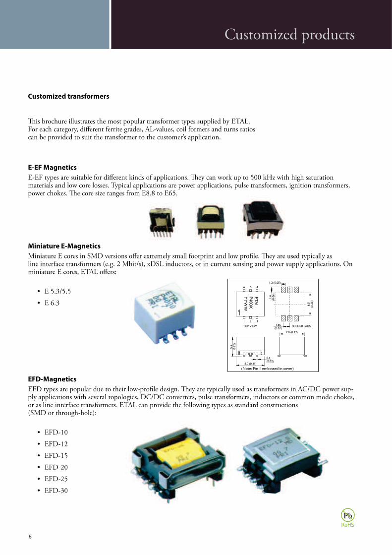
E-EF Magnetics
E-EF types are suitable for different kinds of applications. $ey can work up to 500 kHz with high saturation materials and low core losses. Typical applications are power applications, pulse transformers, ignition transformers, power chokes. $e core size ranges from E8.8 to E65.
Miniature E-Magnetics
Miniature E cores in SMD versions offer extremely small footprint and low profile. $ey are used typically as line interface transformers (e.g. 2 Mbit/s), xDSL inductors, or in current sensing and power supply applications. On miniature E cores, ETAL offers:
EFD-Magnetics
EFD types are popular due to their low-profile design. $ey are typically used as transformers in AC/DC power sup-ply applications with several topologies, DC/DC converters, pulse transformers, inductors or common mode chokes, or as line interface transformers. ETAL can provide the following types as standard constructions (SMD or through-hole):
Customized transformers
E8.8 to E65.
$is brochure illustrates the most popular transformer types supplied by ETAL. For each category, different ferrite grades, AL-values, coil formers and turns ratios can be provided to suit the transformer to the customer’s application.
Customized products

7
EP-Magnetics
EP types offer small footprint and magnetically shielded winding. $ey are typically used in xDSL applications, telecom line interfaces, or as inductors and common mode chokes. Depending on the format they are available for SMD or through-hole insertion. ETAL specializes in:
RM-Magnetics
$e RM format is a widely known compact construction suitable for high density integration on PCBs. RM-magnetics are mainly used in telecom and ISDN line interfaces, power supply applications, inductors and fil-ters. ETAL specializes in the following types (SMD or through-hole):
Customized products

8
Planar Transformers
Planar transformers are the latest constructions to be used in power supply applications, mainly due to their low profile, high efficiency and stable electric values. Advantages of planar technology when compared to conventional construction are e.g. low profile, low weight, very low leakage inductance, low losses and low interwinding capaci-tances. ETAL has specialized in planars with power range up to 300 W, PCB layers up to 16 and ferrite core shapes according to customer’s needs.
Other Ferrite Transformers
On request, ETAL can provide magnetics based on other core sizes and core types such as ER, ETD, PQ, Rod and Toroid. Please advise your requirements through your local ETAL distributor or representative, or contact any of the ETAL sales offices.
Customized products

9
Through Hole Encapsulated
Line Transformer
Part Number Modem Standard Data Rate
kbps
Frequency
Response LF
Hz max
Frequency
Response HF
kHz min
Flatness
±dB max
Return Loss
dB min
Isolation
kV DC min
Sum of
winding
resistance
Max dimensions
L x W x H
P1165 V.32bis 14.4 30 (typ) 15 (typ) 0.2 18 5.5 120 (typ) 19.5x15.2x11
P1200 V.32bis 14.4 50 10 0.2 18 5.5 134 (typ) 18x18x12.6
P2001 V.34+ 33.6 50 10 0.2 18 5.5 146 (typ) 18x18x12.6
P2602 V.32bis (with tap) 14.4 50 10 0.2 18 5.5 134 (typ) 18x18x12.6
P3034 V.34+ 33.6 50 10 0.2 18 5.5 134 (typ) 18x18x12.6
P3065 V.34 33.6 30 (typ) 15 (typ) 0.2 16 5.5 190 (typ) 19.5x15.2x11
P3126 V.32bis 14.4 50 10 0.2 18 5.5 134 (typ) 18x18x12.6
P3146 V.92 56 10 6 0.6 16 5.5 200 (typ) 18x18x12.6
P3156 V.92 56 10 8 0.2 14 5.5 280 (typ) 19.5x15.2x11
P3176 V.92 56 10 6 0.6 16 5.5 200 (typ) 18x18x12.6
P3357 V.92 56 10 55 0.1 16 3.0 186 (typ) 18x18x12.6
P5059 V.92 56 10 60 0.1 16 3.0 194 (typ) 17.8x17.8x11.8
Through Hole Unencapsulated
Line Transformer
Part Number Modem Standard Data Rate
kbps
Frequency
Response
LF Hz
max
Frequency
Response
HF kHz
min
Flatness
±dB
max
Return
Loss dB
min
Isolation
kV DC
min
Primary
winding
resistance
Secondary
winding
resistance
Max dimensions
L x W x H
P3189 V.22bis+voice 2.4 0.2 18 3 69 69 18x18x12.7
P3303 Legerity SLAC (5V) 2.4 30 (typ) 90 (typ) 0.1 20 3 38 53 18x18x12.7
P3304 Legerity SLAC (3.3V) 2.4 30 (typ) 90 (typ) 0.1 20 3 38 25 18x18x12.7
P3324 V.22bis+voice 2.4 30 (typ) 55 (typ) 0.1 16 3 78 108 18x18x12.7
P3356 V.92 56 10 (typ) 55 (typ) 0.1 16 3 78 108 18x18x12.7
P5011 V.34, V.90, V.92 56 10 (typ) 30 (typ) 0.1 20 3 135 130 18.1x17.6x11.2
P5056 V.92 56 10 (typ) 60 (typ) 0.1 20 3 103 98 18.1x17.6x11.2
P5097 V.34, V.90, V.92 56 10 (typ) 30 (typ) 0.1 20 3 135 130 18.1x17.6x11.2
P5100 V.32bis 14.4 0.2 18 3 67 67 18.1x17.6x11.2
P5122 V.22bis+voice 2.4 0.2 18 3 69 69 18.1x17.6x11.2
P5233 V.92 56 10 (typ) 60 (typ) 0.1 16 3 96 93 17.5x16.5x10.4
P5273 V.34, V.90, V.92 56 10 (typ) 30 (typ) 0.1 20 3 135 130 17.5x16.5x10.4
Surface Mount Line Transformer
Part Number Modem Standard Data Rate
kbps
Frequency
Response
LF Hz max
Frequency
Response
HF kHz
min
Flatness
±dB max
Return
Loss dB
min
Isolation
kV DC min
Primary
winding
resistance
Secondary
winding
resistance
Max dimensions
L x W x H
P2781 V.32bis 14.4 50 (typ) 40 (typ) 0.2 18 5.5 112 112 13x9x7
P2782 V.32bis 14.4 50 (typ) 40 (typ) 0.2 18 5.5 112 56+56 13x9x7
P3000 V.92 2-4 wire hybrid 56 0.1 17 5.5 18x12.7x7
P3081 V.34+ 33.6 50 (typ) 30 (typ) 0.2 16 5.5 170 170 13x9x7
P3181 V.92 56 0.2 16 5.5 225 250 13x9x7
P3188 V.22bis 2.4 0.2 18 5.5 94 94 13x9x7
P3191 V.34+ 33.6 50 (typ) 35 (typ) 0.2 16 5.5 151 151 13x9x7
Standard products

10
High Impedance ‘Pick O"’ Transformer
Part Number Pin/SMD Turns Ratio Impedance
ratio
Input
impedance
k
Leakage
inductance
mH
Shunt
inductance
Lp H
Shunt loss
Rp k
Isolation
kV DC
min
Sum of
windings DCR
(
Max dimensions
L x W x H
P1727 TH 2.162 4.67:1 12 160 (max) 22 (min) 50 (min) 5.5 1537 (max) 18x18x12.6
P2152 TH 1.732 3:1 50 330 (typ) 150 (typ) 300 (typ) 5.5 2550 (typ) 18x18x12.6
P2769 SMD 2.162 (1:1) 1:1 30 67 (typ) 30 (typ) 110 (typ) 5.5 3300 (typ) 13x9x7
P3127 TH 1.732 3:1 20 170 (typ) 53 (typ) 70 (min) 5.5 1860 (max) 18,5x18,5x14.6
P3190 SMD 2.162 (1:1) 1:1 10 20 (typ) 11 (typ) 44 (typ) 5.5 968 (typ) 13x9x7
Planar Power Transformer
Part Number Pin/ SMD Turn Ratio Pri DCR
m
Sec DCR
m
Aux DCR
m
Leakage
inductance
nH
Primary
inductance
Lp H
Frequency Total loss
Watt
Isolation
Vrms min
Max dimensions
L x W x H
P6130 SMD 8:2+2 68 9.2 N/A 0.09 78.1 10-150kHz 0.5 750 13.7x11x4.9
P6131 SMD 12:2+2 100 9.0 N/A 0.25 175.68 10-150kHz 0.5 750 13.7x11x4.9
P6132 SMD 8:1+1 68 2.3 N/A 0.2 78.1 10-150kHz 0.5 750 13.7x11x4.9
P6133 SMD 11:1+1 90 2.3 N/A 0.35 147.6 10-150kHz 0.5 750 13.7x11x4.9
P6134 SMD 9:1+1 88 2.3 N/A 0.2 98.82 10-150kHz 0.5 750 13.7x11x4.9
P6135 SMD 8:3+3 68 20 N/A 0.09 78.1 10-150kHz 0.5 750 13.7x11x4.9
P6140-1 SMD 3:1 16 4.5 70 100 2.25 100-350kHz 0.6 500 25x18x6
P6140-2 SMD 3:1 16 4.5 70 100 2.84 350-500kHz 0.6 500 25x18x6
P6141 SMD 3:2CT 20 7.5 N/A 100 25 100-500kHz 0.7 500 25x18x6
P6142-1 SMD 7:1 7 4.5 70 100 1.0 350-500kHz 0.6 500 25x18x6
P6142-2 SMD 7:1 7 4.5 70 100 1.26 100-350kHz 0.6 500 25x18x6
Standard products

11
Standard products
$e family of transformers P2820, P2821, P2822, P2823 and P2824 is specifically designed to provide signal coupling with safety for Powerline Carrier applications over four bands from 40kHz to 148.5kHz.
Typically, the devices are driven from low-impedance sources and are connected to the main network using capacitors whose values are chosen to resonate with the transformer leakage inductance. $ey are particularly suitable for use with tri-state power amplifiers, e.g. Texas Instruments TLE2301.
Powerline Carrier Isolation Transformers P2820, P2821, P2822, P2823, P2824
Summary Speci#cationTypical lumped parameters as equivalent circuit pins 1-3.
Parameter Condition P2820 P2821 P2822 P2823 P2824 Units
Series resistance Rs
(DCR+ AC resistance)
1V 100kHz 0.5 0.6 1.0 1.3 1.3
Leakage inductance L 1V 100kHz 14.4 22 46 58 46 µH
Shunt inductance Lp 1V 100kHz 400 600 1200 1600 1200 µH
Shunt loss Rp 1V 100kHz >20 >20 >20 >20 50* k
Turns ratio, N 1V 100kHz 1.67 3.22 3.15 3.00 1.00
Dimensions
e2
Equivalent Circuit
ETALDOC 345/10 Page 3 of 6
IDEAL1:N
At T = 25ºC
Connections
Tolerance ±0.3 mm (±0.012 inch)
Recommended PCB hole size 1 mm Ø (0.04 inch)
Typical applications for our xDSL low distortion series is ADSL over POTS with multiple brands of chipsets, even combined with ISDN. Products have Industry Standard Footprint and are certified to IEC 60950 for supplementary insulation for a primary circuit, 250V working voltage, and are supported by an IEC CB Test Certificate.
$e safety system yields very low transformer parasitics, ensuring that our DSL products exhibits excellent frequency response and balance, in combination with good harmonic distortion performance. $e product range is ideally suited to low cost yet demanding applications.
ADSL Transformers
Part Number Pin/SMD Turns Ratio Primary
Inductance
Leakage induct-
ance (max)
Isolation kV
DC min
Max dimensions
L x W x H
P5300 SMD 2.0 0.4 mH 6.5 uH 3.0 17.15x12.9x12.2
P5341 TH 2.0 1.5 mH 14 uH 3.0 13.6x14.0x13.4
P5342 TH 2.0 0.4 mH 8 uH 3.0 13.6x14.0x13.4
* P2824 shunt loss: Condition 1V 125kHz
th
n for a Certificate.
products exhibits

12
Dimensions Connections
Typical applications
High Voltage Isolation DC-DC Converter Transformer P2460
P2460 is a high voltage isolation transformer for use with low power DC-DC converter circuits. Designed specifically for 5V to 5V applications up to 1W using Maxim MAX253 and MAX845, P2460 provides reinforced insulation to safety standards IEC 60950, EN 60950 and UL 60950 at a working voltage of 250Vrms, and operates over a wide temperature range -40ºC to +85ºC. P2460 is compliant with RoHS Directive 2002/95/EC, and suitable for lead-free and conventional placement and reflow.
Summary Speci#cation
Values at T = 25ºC, unless otherwise stated.
e2
Parameter Conditions Min Typ Max Units
Primary Inductance 100kHz 250mV 1-4 (link 2-3) 320 500 - μH
Turns ratio 8-5 (link 6-7) : 1-4 (link 2-3) - 1.3 - -
DC resistance 1-2, 3-4 - - 0.5 Ω 5-6, 7-8 - - 0.5 Ω
ET product 1-2, 3-4 18 - - Vμs
Dielectric strength Pri : sec 4500 - - Vrms
Operating range Ambient temperature -40 - +85 ºC
1
2
3
4
6
8
1
2
3
4 5
6
7
8
0.1µF 22µF
+
–
P2460
MAX 253MAX 845
FREQUENCYSELECT
___ON/OFF
0.1µF
+5V
7
5V @ 200mA
Standard products
13
Dimensions Connections Typical application
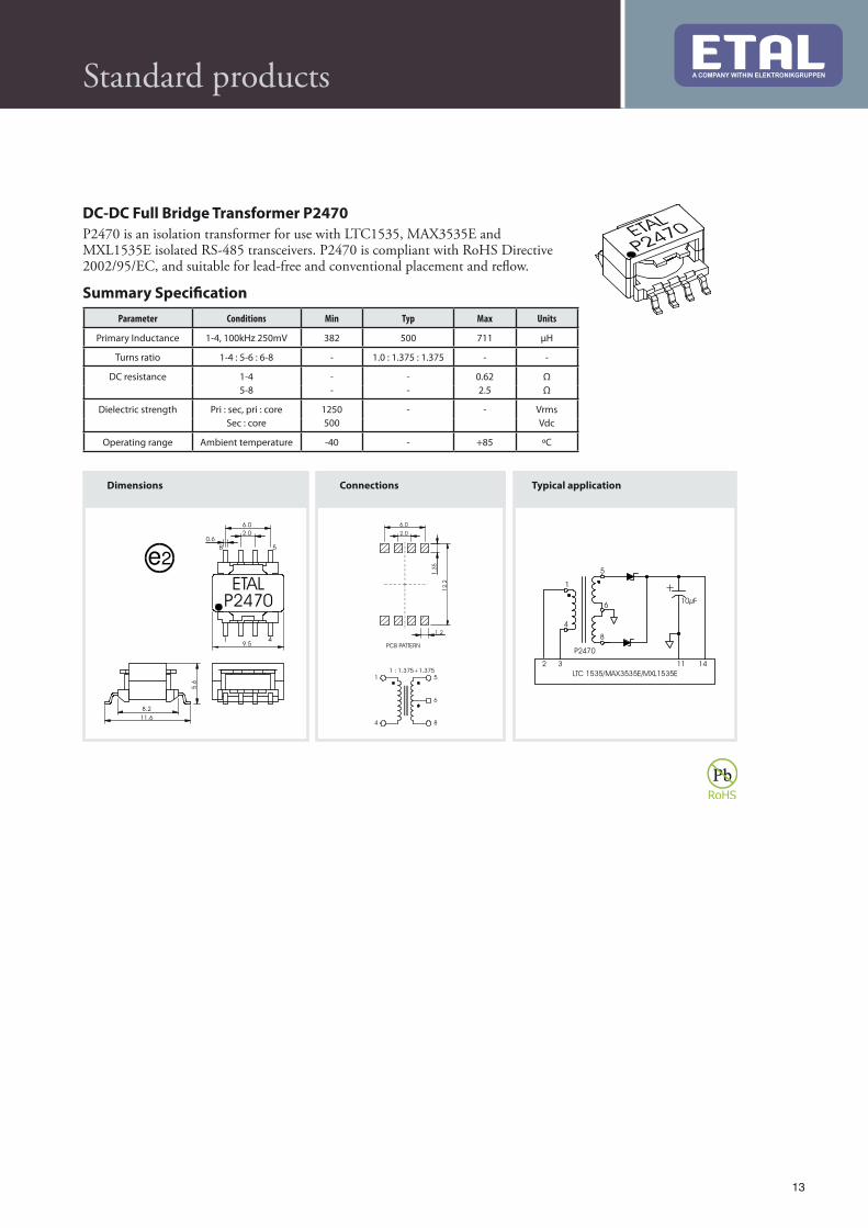
DC-DC Full Bridge Transformer P2470
P2470 is an isolation transformer for use with LTC1535, MAX3535E and MXL1535E isolated RS-485 transceivers. P2470 is compliant with RoHS Directive 2002/95/EC, and suitable for lead-free and conventional placement and reflow.
Summary Speci#cation
Parameter Conditions Min Typ Max Units
Primary Inductance 1-4, 100kHz 250mV 382 500 711 μH
Turns ratio 1-4 : 5-6 : 6-8 - 1.0 : 1.375 : 1.375 - -
DC resistance 1-4 - - 0.62 Ω
5-8 - - 2.5 Ω
Dielectric strength Pri : sec, pri : core 1250 - - Vrms
Sec : core 500 Vdc
Operating range Ambient temperature -40 - +85 ºC
Standard products

14
Standard products
Dimensions Connections
DC-DC Converter Transformer P2480
P2480 is a voltage isolation transformer for use with low power DC-DC converter circuits. P2480 is designed for applications using Maxim MAX253 and MAX845, and operates over a wide temperature range -40ºC to +85ºC. P2480 is compliant with RoHS Directive 2002/95/EC, and suitable for lead-free and conventional placement and reflow.
Summary Speci#cation
Parameter Conditions Min Typ Max Units
Primary Inductance 10kHz 250mV 1-3 400 - - μH
Turns ratio 6-4 CT : 1-3 CT - 1.3 - -
DC resistance 1-3 - - 0.95 Ω
6-4 - - 1.25 Ω
ET product 1-3 - 27 - Vμs
Dielectric strength Pri : sec 1500 - - Vrms
Operating range Ambient temperature -40 - +85 ºC

15
8
7
PWMCurrentMode driver
RL Output load
Convertertransformer
0V
0V
DC input
P407
7.9
(0
.31)
5.6 (0.22)
5.3
(0.2
1)
4.9
(0.1
9)
3.7 (0.14)
0.6
(0.02)
2.4
(0.0
9)
5.3 (0.21)
456
1 2 3
78
PIN 1
MARKER
See fig 3
Fig. 1
e3
Terminals pure tin (Sn). JESD97 category = e3.
2.7
(0.1
1)
2.5
(0.1
0)
3.0 (0.12)
5.5 (0.22) 1.6
(0.06)
3.7
0.1
5)
1.2
(0.0
5)
1
2
3 4
5
6
7
8
Parameter Conditions Min Typ Max Units
Turns Ratio, N — 70 — —
Secondary Inductance 10kHz, 250mV 980 — — µH
Primary DC resistance — 0.6 0.8 m
Secondary DC resistance — 3.5 4.75
Voltage isolation 50Hz 500 — — Vrms
Operating range:
Functional
Storage
Ambient temperature
-25
-40
—
—
+105
+125
°C
°C
Speci#cations
Electrical. At T = 25 °C, unless otherwise stated.
Other turns ratios can be supplied. Please contact ETAL Technologies with your requirements.
$e P407 family is intended for measuring instantaneous current in switching applications. By using a current transformer to mirror current, the need for a sense resistor, with its associated power losses, is avoided.
P407 has a current ratio of 70:1 and is suitable for sense currents up to 10A and switching frequencies in the range 50kHz to 1MHz. Four variants are available to suit different pinouts and phasing.
Functional insulation is provided between primary (sense) and secondary windings to insulation Class B (130ºC).
10 Amp Current Sense Transformer P407
P407 dimensions
P407 PCB patternP407 Typical application
Standard products

16
Winding diagram Footprint (mm)
CAN BUS CHOKE 2824TFxxxxSCLF Series
CAN BUS common mode choke series 5 - 4700 µH
L [µH] Type no. Marking Ordering code
5 2824TF0053SCLF 0053SCLF 191004
11 2824TF0113SCLF 0113SCLF 191010
25 2824TF0253SCLF 0253SCLF 191017
51 2824TF0513SCLF 0513SCLF 191025
470 2824TF4703SCLF 4703SCLF 191029
1000 2824TF1004SCLF 1004SCLF 191034
2200 2824TF2204SCLF 2204SCLF 191040
4700 2824TF4704SCLF 4704SCLF 191045
Test: Pin: TF0053SCLF TF0113SCLF TF0253SCLF TF0513SCLF TF4703SCLF Unit: Condition
min typ max min typ max min typ max min typ max min typ max
Inductance: 1-4 / 2-3 3,5 5.00 6,5 7,7 11.00 14,3 17,5 25.00 32,5 35,7 51.00 66,3 329 470 611 µH @ 100kHz / 10mV
Leakage inductance: 1-4 (s 2-3) 0.065 0.065 1.5 2.6 0.26 µH @ 100kHz / 10mV
DC Resistance: 1-4 / 2-3 0.13 0.156 0.13 0.3 0.325
TRP: 1-4 / 2-3 1 : 1 +/– 5% 1 : 1 +/– 5% 1 : 1 +/– 5% 1 : 1 +/– 5% 1 : 1 +/– 5% @ 100kHz / 10mV
Hi-pot wdg - wdg 500 250 250 250 750 VAC 0,50mA, 2 sec
Idc 1200 800 800 800 700 mA
CM Insertion loss 1-4 (s1-2/4-3) -14 -20 -26 -25 -28 dB
@ Condition 200 MHz 100 MHz 70 MHz 100 MHz 20 MHz
Test: Pin:
Inductance: 1-4 / 2-3
Leakage inductance: 1-4 (s 2-3)
DC Resistance: 1-4 / 2-3
TRP: 1-4 / 2-3
Hi-pot wdg - wdg
Idc
CM Insertion loss 1-4 (s1-2/4-3)
TF1004SCLF Unit: Conditionmin typ max
0,7 1.00 1,5 mH @ 100kHz / 10mV
0.26 µH @ 100kHz / 10mV
0.26
1 : 1 +/– 5% @ 100kHz / 10mV
750 VAC 0,50mA, 2 sec
700 mA
-33 dB
6 MHz
TF2204SCLF TF4704SCLF Unit: Conditionmin typ max min typ max
1,54 2.2 3,3 3,29 4.7 7,05 mH @ 10kHz / 10mV
0.325 0.5 µH @ 10kHz / 10mV
0.52 1.3
1 : 1 +/– 5% 1 : 1 +/– 5% @ 10kHz / 10mV
750 750 VAC 0,50mA, 2 sec
500 400 mA
-36 -40 dB
3 MHz 1.5 MHz
Standard products
(Marking)

17
Winding diagram Footprint (mm)
CAN BUS CHOKE 2824TFxxxxSTLF Series
CAN BUS common mode choke series 5 - 4700 µH
L [µH] Type no. Marking Ordering code
5 2824TF0053STLF 0053STLF 191005
11 2824TF0113STLF 0113STLF 191011
25 2824TF0253STLF 0253STLF 191018
51 2824TF0513STLF 0513STLF 191024
470 2824TF4703STLF 4703STLF 191028
1000 2824TF1004STLF 1004STLF 191033
2200 2824TF2204STLF 2204STLF 191041
4700 2824TF4704STLF 4704STLF 191046
Test: Pin: TF0053STLF TF0113STLF TF0253STLF TF0513STLF TF4703STLF Unit: Conditionmin typ max min typ max min typ max min typ max min typ max
Inductance: 1-4 / 2-3 3,5 5.00 6,5 7,7 11.00 14,3 17,5 25.00 32,5 35,7 51.00 66,3 329 470 611 µH @ 100kHz / 10mV
Leakage inductance: 1-4 (s 2-3) 0.065 0.065 1.5 2.6 0.26 µH @ 100kHz / 10mV
DC Resistance: 1-4 / 2-3 0.13 0.156 0.13 0.3 0.325
TRP: 1-4 / 2-3 1 : 1 +/– 5% 1 : 1 +/– 5% 1 : 1 +/– 5% 1 : 1 +/– 5% 1 : 1 +/– 5% @ 100kHz / 10mV
Hi-pot wdg - wdg 500 250 250 250 750 VAC 0,50mA, 2 sec
Idc 1000 500 500 500 500 mA
CM Insertion loss 1-4 (s1-2/4-3) -14 -20 -26 -25 -28 dB
@ Condition 200 MHz 100 MHz 70 MHz 100 MHz 20 MHz
Test: Pin:
Inductance: 1-4 / 2-3
Leakage inductance: 1-4 (s 2-3)
DC Resistance: 1-4 / 2-3
TRP: 1-4 / 2-3
Hi-pot wdg - wdg
Idc
CM Insertion loss 1-4 (s1-2/4-3)
TF1004STLF Unit: Conditionmin typ max
0,7 1.00 1,5 mH @ 100kHz / 10mV
0.26 µH @ 100kHz / 10mV
0.26
1 : 1 +/– 5% @ 100kHz / 10mV
750 VAC 0,50mA, 2 sec
500 mA
-33 dB
6 MHz
TF2204STLF TF4704STLF Unit: Conditionmin typ max min typ max
1,54 2.2 3,3 3,29 4.7 7,05 mH @ 10kHz / 10mV
0.325 0.5 µH @ 10kHz / 10mV
0.52 1.3
1 : 1 +/– 5% 1 : 1 +/– 5% @ 10kHz / 10mV
750 750 VAC 0,50mA, 2 sec
400 200 mA
-36 -40 dB
3 MHz 1.5 MHz
Standard products
(Marking)
18
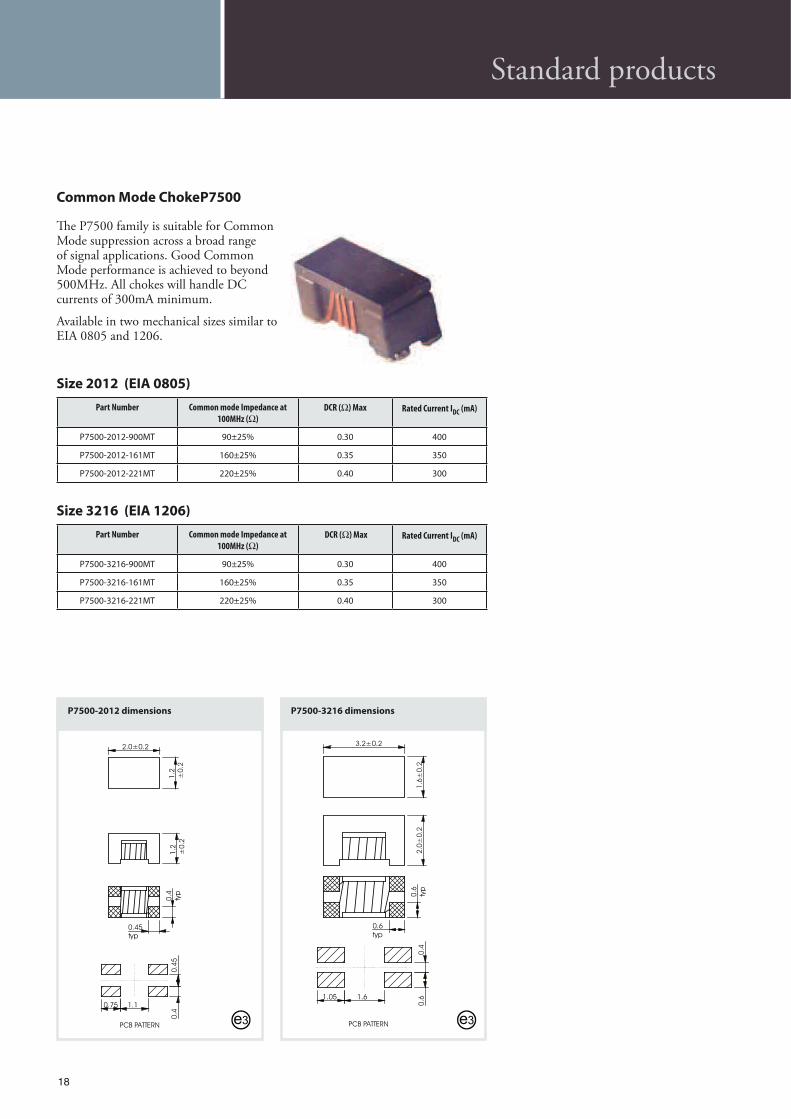
Size 2012 (EIA 0805)
Part Number Common mode Impedance at
100MHz ( )
DCR ( ) Max Rated Current IDC (mA)
P7500-2012-900MT 90±25% 0.30 400
P7500-2012-161MT 160±25% 0.35 350
P7500-2012-221MT 220±25% 0.40 300
Size 3216 (EIA 1206)
Part Number Common mode Impedance at
100MHz ( )
DCR ( ) Max Rated Current IDC (mA)
P7500-3216-900MT 90±25% 0.30 400
P7500-3216-161MT 160±25% 0.35 350
P7500-3216-221MT 220±25% 0.40 300
$e P7500 family is suitable for Common Mode suppression across a broad range of signal applications. Good Common Mode performance is achieved to beyond 500MHz. All chokes will handle DC currents of 300mA minimum.
Available in two mechanical sizes similar to EIA 0805 and 1206.
Common Mode Choke P7500
e3
P7500-3216 dimensions
2.0±0.2
1.2
±0.2
1.2
±0.2
1.10.75
0.4
0.4
50.4
typ
0.45
typ
PCB PATTERN
P7500-2012 dimensions
E
3.2±0.2
1.6
±0.2
2.0
±0.2
0.6
typ
0.6
typ
1.61.05
0.6
0.4
PCB PATTERN e3
Standard products

19
Size 1813
Part Number Inductance (µH) DCR (m ) SRF (MHz) Rated Current IRMS
(A)Isat (A)
P7601-1813-R56M 0.56±20% 10 200 6.0 7.7
P7601-1813-1R2M 1.2±20% 17 140 4.4 5.3
P7601-1813-2R2M 2.2±20% 35 100 3.1 3.5
P7601-1813-4R7M 4.7±20% 54 50 2.2 2.6
P7601-1813-100M 10±20% 111 40 1.5 1.9
P7601-1813-150M 15±20% 170 30 1.2 1.5
P7601-1813-220M 22±20% 250 25 1.0 1.2
P7601-1813-330M 33±20% 350 20 0.8 1.0
P7601-1813-470M 47±20% 470 15 0.7 0.9
$e P7601 family comprises high current, unshielded power inductors. Components are available in three mechanical sizes, suitable for low-profile high current applications. $e miniature 1813 parts have very high current rating for their size; the 3316 and 5022 parts exhibit very low DCR. $e family employs heavy gauge wire to minimize DCRs, and provides reliable self-leaded Pb-free terminations.
High Power Inductor P7601
ma
x6.1
max8.9
ma
x5.0
5.02.0
4.0
MARKINGINDUCTANCE CODE
PCB PATTERN e3
ma
x9.9
max13.5
ma
x6.3
5
8.41.8
5.0
MARKINGINDUCTANCE CODE
PCB PATTERNe3
E
ma
x16
.3
max22.4
m
ax
8.0
14.33.2
8.7
MARKINGINDUCTANCE CODE
PCB PATTERN e3
Standard products
Size 3316
Part Number Inductance (µH) DCR (m ) SRF (MHz) Rated Current IRMS
(A)Isat (A)
P7601-3316-R12M 0.12±20% 1.5 350 20 20
P7601-3316-R33M 0.33±20% 2 300 16 20
P7601-3316-R68M 0.68±20% 5 200 12 13
P7601-3316-1R0M 1.0±20% 6 100 10 11
P7601-3316-1R5M 1.5±20% 8 90 9 9
P7601-3316-2R2M 2.2±20% 11 90 7.4 7.8
P7601-3316-2R7M 2.7±20% 12 65 6.6 7.0
P7601-3316-3R3M 3.3±20% 14 65 5.9 6.4
P7601-3316-4R7M 4.7±20% 18 45 4.8 5.9
P7601-3316-5R6M 5.6±20% 22 40 4.6 5.0
P7601-3316-6R8M 6.8±20% 27 36 4.4 4.6
P7601-3316-8R2M 8.2±20% 32 28 4.0 4.0
P7601-3316-100M 10±20% 38 25 3.9 3.8
Size 5022
Part Number Inductance (µH) DCR (m ) SRF (MHz) Rated Current IRMS
(A)Isat (A)
P7601-5022-R78M 0.78±20% 2.6 156 15 30
P7601-5022-1R5M 1.5±20% 4 100 15 25
P7601-5022-2R2M 2.2±20% 6 75 12 20
P7601-5022-3R3M 3.3±20% 8 60 10 17
P7601-5022-3R9M 3.9±20% 10 55 9 15
P7601-5022-4R7M 4.7±20% 14 40 8.4 13
P7601-5022-6R0M 6.0±20% 17 35 7.5 12
P7601-5022-7R8M 7.8±20% 18 35 7.5 11
P7601-5022-100M 10±20% 26 28 6.0 10
P7601-5022-150M 15±20% 32 20 4.4 8
P7601-1813 dimensions
P7601-3316 dimensions
P7601-5022 dimensions

20
Shielded Power Inductor P7602
Size 0603
Part Number Inductance (µH) DCR
(m )
Rated Cur-rent IRMS
(A)Isat
(A) Rated
Current IDC
P7602-0603-2R0M 2.0±20% 19 3.3 3.0 -
P7602-0603-2R7M 2.7±20% 22 3.1 2.7 -
P7602-0603-3R3M 3.3±20% 26 2.8 2.6 -
P7602-0603-4R7M 4.7±20% 32 2.5 2.1 -
P7602-0603-6R2M 6.2±20% 35 2.4 1.8 -
P7602-0603-8R2M 8.2±20% 44 2.1 1.5 -
P7602-0603-100M 10±20% 50 2.0 1.5 -
P7602-0603-120M 12±20% 62 1.7 1.3 -
P7602-0603-150M 15±20% 77 1.5 1.1 -
P7602-0603-180M 18±20% 82 1.5 1.0 -
P7602-0603-220M 22±20% 106 1.3 0.97 -
P7602-0603-270M 27±20% 140 1.1 0.82 -
P7602-0603-330M 33±20% 162 1.0 0.76 -
P7602-0603-390M 39±20% 192 0.96 0.70 -
P7602-0603-470M 47±20% 209 0.89 0.68 -
P7602-0603-560M 56±20% 257 0.80 0.60 -
P7602-0603-680M 68±20% 320 0.71 0.56 -
P7602-0603-820M 82±20% 420 0.61 0.47 -
P7602-0603-101M 100±20% 477 0.57 0.45 -
P7602-0603-151M 150±20% 664 0.48 0.37 -
$e P7602 family comprises low profile, shielded power inductors. Components are available in two mechanical sizes, suited to low-profile applications. $e larger 1003 size has lower DCR and higher current rating.
6.4 max
6.3
ma
x3.5
ma
x
4.61.0
2.6
2.0
typ
0.6typ
MARKINGINDUCTANCE CODE
PCB PATTERN
e4
E
10.4 max
10.3
ma
x4.0
ma
x
7.31.8
3.2
1.5typ
typ
3.0
MARKINGINDUCTANCE CODE
PCB PATTERN
e4
Standard products
Size 1003
Part Number Inductance (µH) DCR
(m )
Rated Cur-rent IRMS
(A)Isat
(A) Rated
Current IDC
P7602-1003-1R5Y 1.5±30% 8.1 - - 10
P7602-1003-2R5Y 2.5±30% 10 - - 7.5
P7602-1003-3R8Y 3.8±30% 13 - - 6
P7602-1003-5R2Y 5.2±30% 22 - - 5.5
P7602-1003-7R0Y 7.0±30% 27 - - 4.8
P7602-1003-100Y 10±30% 35 - - 4.4
P7602-1003-150Y 15±30% 50 - - 3.6
P7602-1003-220Y 22±30% 73 - - 2.9
P7602-1003-330Y 33±30% 93 - - 2.3
P7602-1003-470Y 47±30% 128 - - 2.1
P7602-1003-680Y 68±30% 213 - - 1.5
P7602-1003-101Y 100±30% 304 - - 1.35
P7602-1003-151Y 150±30% 506 - - 1.15
P7602-1003-221Y 220±30% 756 - - 0.92
P7602-1003-331Y 330±30% 1090 - - 0.70
P7602-1003 dimensions
P7602-0603 dimensions

21
Standard products
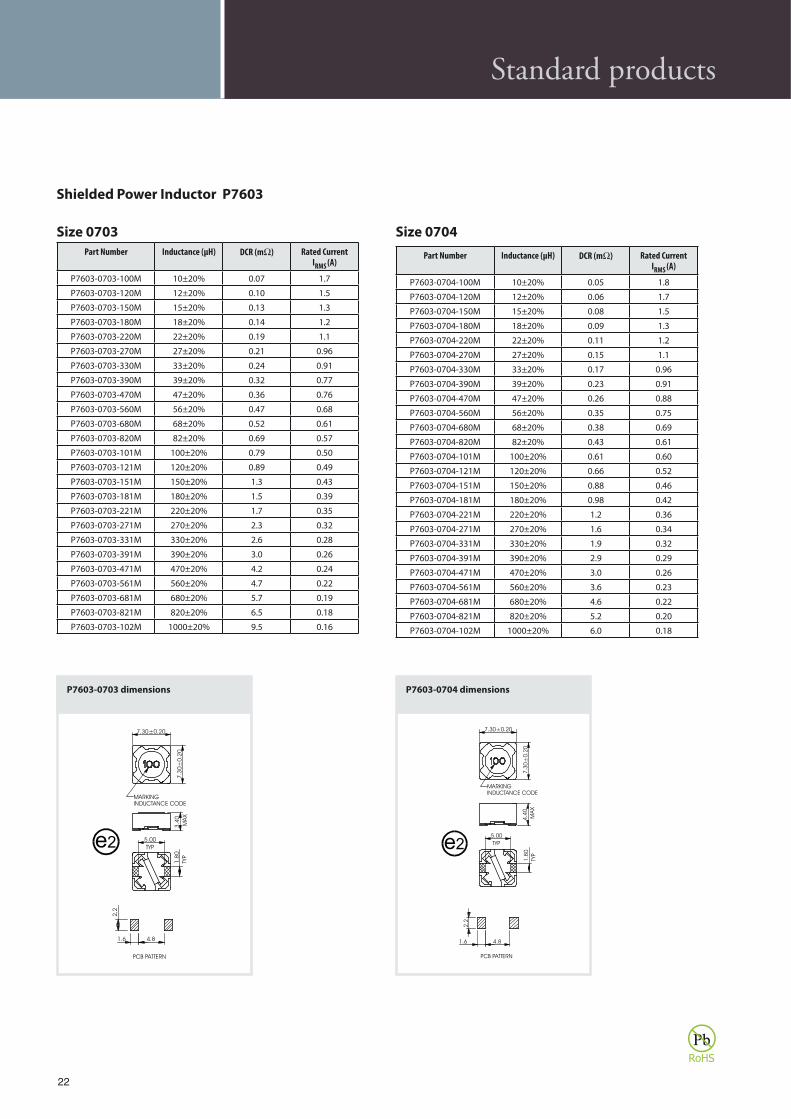
Shielded Power Inductor P7603
Fig. 2
5.90±0.30
5.9
0±
0.3
0
MA
X
5.0
0
TYP
4.60
TYP
1.5
0
1.40
1.9
0
6.60±0.30
4.60
TYP
0.6
0
PCB PATTERN
MARKINGINDUCTANCE CODE
e2
P7603-0605 dimensions
5.90±0.30
5.9
0±
0.3
0
MA
X
3.0
0
TYP
4.60
TYP
1.5
0
1.9
4.61.4
TYP
0.6
0
PCB PATTERN
MARKINGINDUCTANCE CODE
6.60±0.30
e2
P7603-0603 dimensions
$e P7603 family comprises high current, shielded power inductors. Components are available in eight mechanical sizes, suitable for low-profile high current applications. $e family employs heavy gauge wire to minimize DCRs, and provides reliable self-leaded Pb-free terminations. Parts are compliant with RoHS Directive 2002/95/EC, and suitable for Pb-free and conventional placement and reflow.
Size 0603
Part Number Inductance (µH) DCR (m ) Rated Current IRMS
(A)
P7603-0603-2R9M 2.9±20% 0.07 1.9
P7603-0603-4R0M 4.0±20% 0.08 1.6
P7603-0603-5R5M 5.5±20% 0.09 1.4
P7603-0603-100M 10±20% 0.15 1.1
P7603-0603-120M 12±20% 0.20 1.0
P7603-0603-150M 15±20% 0.23 0.90
P7603-0603-180M 18±20% 0.27 0.80
P7603-0603-220M 22±20% 0.34 0.74
P7603-0603-270M 27±20% 0.38 0.66
P7603-0603-330M 33±20% 0.45 0.59
P7603-0603-390M 39±20% 0.49 0.54
P7603-0603-470M 47±20% 0.69 0.50
P7603-0603-560M 56±20% 0.78 0.46
P7603-0603-680M 68±20% 1.1 0.42
P7603-0603-820M 82±20% 1.2 0.38
P7603-0603-101M 100±20% 1.4 0.34
P7603-0603-121M 120±20% 1.9 0.31
P7603-0603-151M 150±20% 2.2 0.28
P7603-0603-181M 180±20% 2.8 0.26
P7603-0603-221M 220±20% 3.1 0.23
P7603-0603-271M 270±20% 4.4 0.22
P7603-0603-331M 330±20% 4.9 0.19
Size 0605
Part Number Inductance (µH) DCR (m ) Rated Current IRMS
(A)
P7603-0605-100M 10±20% 0.12 1.3
P7603-0605-120M 12±20% 0.13 1.2
P7603-0605-150M 15±20% 0.18 1.1
P7603-0605-180M 18±20% 0.24 1.0
P7603-0605-220M 22±20% 0.27 0.91
P7603-0605-270M 27±20% 0.30 0.82
P7603-0605-330M 33±20% 0.33 0.74
P7603-0605-390M 39±20% 0.37 0.69
P7603-0605-470M 47±20% 0.52 0.62
P7603-0605-560M 56±20% 0.56 0.58
P7603-0605-680M 68±20% 0.63 0.51
P7603-0605-820M 82±20% 0.71 0.46
P7603-0605-101M 100±20% 1.0 0.42
P7603-0605-121M 120±20% 1.2 0.38
P7603-0605-151M 150±20% 1.7 0.35
P7603-0605-181M 180±20% 1.9 0.32
P7603-0605-221M 220±20% 2.1 0.29
P7603-0605-271M 270±20% 2.4 0.26
P7603-0605-331M 330±20% 2.7 0.23
P7603-0605-391M 390±20% 2.9 0.22
P7603-0605-471M 470±20% 3.9 0.20
P7603-0605-561M 560±20% 5.4 0.18
P7603-0605-681M 680±20% 7.3 0.17
P7603-0605-821M 820±20% 8.2 0.15
P7603-0605-102M 1000±20% 9.3 0.14
22
Size 0703
Part Number Inductance (µH) DCR (m ) Rated Current IRMS
(A)
P7603-0703-100M 10±20% 0.07 1.7
P7603-0703-120M 12±20% 0.10 1.5
P7603-0703-150M 15±20% 0.13 1.3
P7603-0703-180M 18±20% 0.14 1.2
P7603-0703-220M 22±20% 0.19 1.1
P7603-0703-270M 27±20% 0.21 0.96
P7603-0703-330M 33±20% 0.24 0.91
P7603-0703-390M 39±20% 0.32 0.77
P7603-0703-470M 47±20% 0.36 0.76
P7603-0703-560M 56±20% 0.47 0.68
P7603-0703-680M 68±20% 0.52 0.61
P7603-0703-820M 82±20% 0.69 0.57
P7603-0703-101M 100±20% 0.79 0.50
P7603-0703-121M 120±20% 0.89 0.49
P7603-0703-151M 150±20% 1.3 0.43
P7603-0703-181M 180±20% 1.5 0.39
P7603-0703-221M 220±20% 1.7 0.35
P7603-0703-271M 270±20% 2.3 0.32
P7603-0703-331M 330±20% 2.6 0.28
P7603-0703-391M 390±20% 3.0 0.26
P7603-0703-471M 470±20% 4.2 0.24
P7603-0703-561M 560±20% 4.7 0.22
P7603-0703-681M 680±20% 5.7 0.19
P7603-0703-821M 820±20% 6.5 0.18
P7603-0703-102M 1000±20% 9.5 0.16
Size 0704
Part Number Inductance (µH) DCR (m ) Rated Current IRMS
(A)
P7603-0704-100M 10±20% 0.05 1.8
P7603-0704-120M 12±20% 0.06 1.7
P7603-0704-150M 15±20% 0.08 1.5
P7603-0704-180M 18±20% 0.09 1.3
P7603-0704-220M 22±20% 0.11 1.2
P7603-0704-270M 27±20% 0.15 1.1
P7603-0704-330M 33±20% 0.17 0.96
P7603-0704-390M 39±20% 0.23 0.91
P7603-0704-470M 47±20% 0.26 0.88
P7603-0704-560M 56±20% 0.35 0.75
P7603-0704-680M 68±20% 0.38 0.69
P7603-0704-820M 82±20% 0.43 0.61
P7603-0704-101M 100±20% 0.61 0.60
P7603-0704-121M 120±20% 0.66 0.52
P7603-0704-151M 150±20% 0.88 0.46
P7603-0704-181M 180±20% 0.98 0.42
P7603-0704-221M 220±20% 1.2 0.36
P7603-0704-271M 270±20% 1.6 0.34
P7603-0704-331M 330±20% 1.9 0.32
P7603-0704-391M 390±20% 2.9 0.29
P7603-0704-471M 470±20% 3.0 0.26
P7603-0704-561M 560±20% 3.6 0.23
P7603-0704-681M 680±20% 4.6 0.22
P7603-0704-821M 820±20% 5.2 0.20
P7603-0704-102M 1000±20% 6.0 0.18
TYP
5.00
TYP
1.8
0
7.30±0.20
7.3
0±
0.2
0
MA
X
4.4
0
1.6 4.8
2.2
PCB PATTERN
MARKINGINDUCTANCE CODE
Fig. 4
e2
P7603-0704 dimensions
TYP
5.00
TYP
1.8
0
7.30±0.20
7.3
0±
0.2
0M
AX
3.4
0
2.2
4.81.6
PCB PATTERN
MARKINGINDUCTANCE CODE
e2
P7603-0703 dimensions
Standard products
Shielded Power Inductor P7603

23
Standard products
Size 1203
Part Number Inductance (µH) DCR (m ) Rated Current IRMS
(A)
P7603-1203-1R5M 1.5±20% 13 7.8
P7603-1203-2R2 2.2±20% 15 6.8
P7603-1203-3R9 3.9±20% 26 5.5
P7603-1203-5R6M 5.6±20% 32 4.8
P7603-1203-8R2M 8.2±20% 45 4.1
P7603-1203-100M 10±20% 50 3.9
P7603-1203-120M 12±20% 60 3.5
P7603-1203-150M 15±20% 80 3.0
P7603-1203-180M 18±20% 100 2.7
P7603-1203-220M 22±20% 110 2.5
P7603-1203-270M 27±20% 130 2.2
P7603-1203-330M 33±20% 160 2.1
P7603-1203-390M 39±20% 180 2.0
P7603-1203-470M 47±20% 220 1.8
P7603-1203-560M 56±20% 260 1.6
P7603-1203-680M 68±20% 310 1.5
P7603-1203-820M 82±20% 360 1.4
P7603-1203-101M 100±20% 400 1.3
P7603-1203-121M 120±20% 530 1.1
P7603-1203-151M 150±20% 610 1.0
P7603-1203-181M 180±20% 800 0.90
P7603-1203-221M 220±20% 970 0.85
P7603-1203-271M 270±20% 1200 0.75
P7603-1203-331M 330±20% 1350 0.70
Size 1204
Part Number Inductance (µH) DCR (m ) Rated Current IRMS
(A)
P7603-1204-3R3M 3.3±20% 15 6.5
P7603-1204-4R7M 4.7±20% 18 5.7
P7603-1204-6R8M 6.8±20% 23 4.9
P7603-1204-100M 10±20% 28 4.5
P7603-1204-120M 12±20% 38 4.0
P7603-1204-150M 15±20% 52 3.2
P7603-1204-180M 18±20% 60 3.1
P7603-1204-220M 22±20% 70 2.9
P7603-1204-270M 27±20% 80 2.8
P7603-1204-330M 33±20% 97 2.7
P7603-1204-390M 39±20% 132 2.1
P7603-1204-470M 47±20% 150 1.9
P7603-1204-560M 56±20% 190 1.8
P7603-1204-680M 68±20% 220 1.5
P7603-1204-820M 82±20% 260 1.3
P7603-1204-101M 100±20% 308 1.2
P7603-1204-121M 120±20% 380 1.1
P7603-1204-151M 150±20% 520 0.95
P7603-1204-181M 180±20% 600 0.85
P7603-1204-221M 220±20% 700 0.80
P7603-1204-271M 270±20% 860 0.60
P7603-1204-331M 330±20% 980 0.50
P7603-1204 dimensions
Fig. 5
12
.5±
0.3
0
12.5±0.30
3.9
MA
X
5.0
7.62.3 2.3
7.02.8
5.4
PCB PATTERN
MARKINGINDUCTANCE CODE
e3
P7603-1203 dimensions
Fig. 6
PCB PATTERN
4.6
ma
x
7.02.8
5.4
12.5
±0.3
12.5±0.3
MARKINGINDUCTANCE CODE
5.0
typ
7.6
typ
2.3
typ
2.3
typ
e3

24
Size 1205
Part Number Inductance (µH) DCR (m ) Rated Current IRMS
(A)
P7603-1205-1R5Y 1.5±25% 12 8.0
P7603-1205-2R2Y 2.2±25% 14 7.0
P7603-1205-3R1Y 3.1±25% 17 6.0
P7603-1205-4R4Y 4.4±25% 20 5.0
P7603-1205-5R2Y 5.2±25% 21 4.4
P7603-1205-7R5Y 7.5±25% 24 4.2
P7603-1205-100M 10±20% 25 4.0
P7603-1205-120M 12±20% 27 3.5
P7603-1205-150M 15±20% 30 3.3
P7603-1205-180M 18±20% 34 3.0
P7603-1205-220M 2±20% 36 2.8
P7603-1205-270M 27±20% 51 2.3
P7603-1205-330M 33±20% 57 2.1
P7603-1205-390M 39±20% 68 2.0
P7603-1205-470M 47±20% 75 1.8
P7603-1205-560M 56±20% 110 1.7
P7603-1205-680M 68±20% 120 1.5
P7603-1205-820M 82±20% 140 1.4
P7603-1205-101M 100±20% 160 1.3
P7603-1205-121M 120±20% 170 1.1
P7603-1205-151M 150±20% 230 1.0
P7603-1205-181M 180±20% 290 0.90
P7603-1205-221M 220±20% 400 0.80
P7603-1205-271M 270±20% 460 0.75
P7603-1205-331M 330±20% 510 0.68
P7603-1205-391M 390±20% 690 0.65
P7603-1205-471M 470±20% 770 0.58
P7603-1205-561M 560±20% 860 0.54
P7603-1205-681M 680±20% 1200 0.48
P7603-1205-821M 820±20% 1340 0.43
P7603-1205-102M 1000±20% 1530 0.40
Size 1207
Part Number Inductance (µH) DCR (m ) Rated Current IRMS
(A)
P7603-1207-1R2Y 1.2±30% 7.0 9.8
P7603-1207-2R7Y 2.7±30% 11.5 8.0
P7603-1207-3R9Y 3.9±30% 13.5 7.5
P7603-1207-4R7Y 4.7±30% 15.8 6.8
P7603-1207-5R6Y 5.6±30% 17.6 6.6
P7603-1207-7R6Y 7.6±30% 20.0 5.9
P7603-1207-100M 10±20% 21.6 5.4
P7603-1207-120M 12±20% 24.3 4.9
P7603-1207-150M 15±20% 27.0 4.5
P7603-1207-180M 18±20% 39.2 3.9
P7603-1207-220M 22±20% 43.2 3.6
P7603-1207-270M 27±20% 45.9 3.4
P7603-1207-330M 33±20% 64.8 3.0
P7603-1207-390M 39±20% 72.9 2.7
P7603-1207-470M 47±20% 100 2.5
P7603-1207-560L 56±15% 110 2.3
P7603-1207-680L 68±15% 140 2.1
P7603-1207-820L 82±15% 160 1.9
P7603-1207-101L 100±15% 220 1.7
P7603-1207-121L 120±15% 250 1.6
P7603-1207-151L 150±15% 280 1.4
P7603-1207-181K 180±10% 350 1.3
P7603-1207-221K 220±10% 390 1.1
P7603-1207-271K 270±10% 560 1.0
P7603-1207-331K 330±10% 640 0.95
P7603-1207-391K 390±10% 700 0.88
P7603-1207-471K 470±10% 980 0.79
P7603-1207-561K 560±10% 1070 0.73
P7603-1207-681K 680±10% 1460 0.67
P7603-1207-821K 820±10% 1640 0.60
P7603-1207-102K 1000±10% 1820 0.55
P7603-1207 dimensions
PCB PATTERN
6.0
ma
x
7.02.8
5.4
12.5
±0.3
12.5±0.3
MARKINGINDUCTANCE CODE
5.0
typ
7.6typ
2.3typ
2.3typ
Fig. 7
e3
P7603-1205 dimensions
PCB PATTERN
8.0
ma
x
7.02.8
5.4
12.5
±0
.3
12.5±0.3
MARKINGINDUCTANCE CODE
5.0
typ
7.6typ
2.3typ
2.3typ
Fig. 8
e3
Standard products
Shielded Power Inductor P7603

25
Standard products
Size 032
Part Number Inductance (µH) DCR ( ) Rated Current IRMS (A)
P7609-032-1R0M 1.0±20% 0.04 1.50
P7609-032-1R4M 1.4±20% 0.05 1.50
P7609-032-2R8M 1.8±20% 0.06 0.80
P7609-032-2R2M 2.2±20% 0.08 0.75
P7609-032-2R7M 2.7±20% 0.10 0.75
P7609-032-3R3M 3.3±20% 0.15 0.60
P7609-032-3R9M 3.9±20% 0.20 0.50
P7609-032-4R7M 4.7±20% 0.20 0.50
P7609-032-5R6M 5.6±20% 0.23 0.45
P7609-032-6R8M 6.8±20% 0.25 0.40
P7609-032-8R2M 8.2±20% 0.30 0.40
P7609-032-100M 10±20% 0.35 0.35
P7609-032-120M 12±20% 0.40 0.35
P7609-032-150M 15±20% 0.50 0.30
P7609-032-180M 18±20% 0.55 0.30
P7609-032-220M 22±20% 0.60 0.30
P7609-032-270M 27±20% 0.70 0.30
P7609-032-330M 33±20% 1.0 0.25
P7609-032-390M 39±20% 1.2 0.25
P7609-032-470M 47±20% 1.5 0.20
P7609-032-560M 56±20% 1.8 0.20
P7609-032-680M 68±20% 2.0 0.18
P7609-032-820M 82±20% 2.5 0.16
P7609-032-101M 100±20% 3.0 0.15
P7609-032-121M 120±20% 3.5 0.14
P7609-032-151M 150±20% 4.0 0.13
P7609-032-181M 180±20% 5.0 0.12
P7609-032-221M 220±20% 5.5 0.10
P7609-032-271M 270±20% 6.0 0.10
P7609-032-331M 330±20% 7.0 0.10
P7609-032-391M 390±20% 8.0 0.10
P7609-032-471M 470±20% 12.0 0.09
Power Inductor P7609
$e P7609 is available in eight low profile sizes (2.2-5.4mm). $e range covers three decades of values from 1µH to 820µH, and provides very cost-effective and compact solutions for medium power applications. In this family Pb-free electrodes are directly plated onto the ferrite. Such terminations provide excellent solderability, terminal strength and heat resistance.
3.5
±0.3
3.0
±0.3
2.2
±0.3
3.5
0.81.6
PCB PATTERN
MARKINGINDUCTANCE CODE
e3
P7609-032 dimensions
Size 043
Part Number Inductance (µH) DCR ( ) Rated Current IRMS (A)
P7609-043-1R0M 1.0±20% 0.033 3.80
P7609-043-1R4M 1.4±20% 0.038 3.30
P7609-043-2R8M 1.8±20% 0.042 2.91
P7609-043-2R2M 2.2±20% 0.047 2.60
P7609-043-2R7M 2.7±20% 0.052 2.43
P7609-043-3R3M 3.3±20% 0.058 2.15
P7609-043-3R9M 3.9±20% 0.076 1.98
P7609-043-4R7M 4.7±20% 0.094 1.70
P7609-043-5R6M 5.6±20% 0.101 1.60
P7609-043-6R8M 6.8±20% 0.117 1.41
P7609-043-8R2M 8.2±20% 0.132 1.26
continued on next page

26
Size 052
Part Number Inductance (µH) DCR ( ) Rated Current IRMS (A)
P7609-052-1R0M 1.0±20% 0.030 4.8
P7609-052-1R4M 1.4±20% 0.035 4.2
P7609-052-2R8M 1.8±20% 0.040 3.8
P7609-052-2R2M 2.2±20% 0.050 3.5
P7609-052-2R7M 2.7±20% 0.055 3.1
P7609-052-3R3M 3.3±20% 0.07 3.0
P7609-052-3R9M 3.9±20% 0.08 2.8
P7609-052-4R7M 4.7±20% 0.09 2.7
P7609-052-5R6M 5.6±20% 0.11 2.2
P7609-052-6R8M 6.8±20% 0.14 1.9
P7609-052-8R2M 8.2±20% 0.15 1.8
P7609-052-100M 10±20% 0.17 1.5
P7609-052-120M 12±20% 0.25 1.4
P7609-052-150M 15±20% 0.28 1.2
P7609-052-180M 18±20% 0.32 1.1
P7609-052-220M 22±20% 0.42 1.0
P7609-052-270M 27±20% 0.45 0.9
P7609-052-330M 33±20% 0.55 0.8
P7609-052-390M 39±20% 0.58 0.75
P7609-052-470M 47±20% 0.83 0.70
P7609-052-560M 56±20% 0.90 0.65
P7609-052-680M 68±20% 0.97 0.60
P7609-052-820M 82±20% 1.2 0.55
P7609-052-101M 100±20% 1.5 0.50
P7609-052-121M 120±20% 1.7 0.47
P7609-052-151M 150±20% 2.0 0.45
P7609-052-181M 180±20% 2.6 0.40
P7609-052-221M 220±20% 3.4 0.35
P7609-052-271M 270±20% 4.0 0.30
P7609-052-331M 330±20% 4.5 0.27
P7609-052-391M 390±20% 5.0 0.25
P7609-052-471M 470±20% 7.0 0.23
P7609-052-561M 560±20% 8.0 0.21
Size 043 (continued)
Part Number Inductance (µH) DCR ( ) Rated Current IRMS (A)
P7609-043-100M 10±20% 0.182 1.15
P7609-043-120M 12±20% 0.21 1.05
P7609-043-150M 15±20% 0.24 0.92
P7609-043-180M 18±20% 0.34 0.84
P7609-043-220M 22±20% 0.38 0.76
P7609-043-270M 27±20% 0.52 0.71
P7609-043-330K 33±10% 0.54 0.64
P7609-043-390K 39±10% 0.59 0.59
P7609-043-470K 47±10% 0.85 0.54
P7609-043-560K 56±10% 0.94 0.50
P7609-043-680K 68±10% 1.12 0.46
1.51.8
4.5
3.2
±0.3
4.0
±0
.3
4.5
±0.3
PCB PATTERN
MARKINGINDUCTANCE CODE
e3
P7609-043 dimensions
5.8
±0.3
5.2
±0.3
2.5
±0.3
1.72.2
5.5
PCB PATTERN
MARKINGINDUCTANCE CODE
e3
P7609-052 dimensions
Standard products
Power Inductor P7609

27
Standard products
Size 054
Part Number Inductance (µH) DCR ( ) Rated Current IRMS (A)
P7609-054-100M 10±20% 0.10 1.44
P7609-054-120M 12±20% 0.12 1.40
P7609-054-150M 15±20% 0.14 1.30
P7609-054-180M 18±20% 0.15 1.23
P7609-054-220M 22±20% 0.18 1.11
P7609-054-270M 27±20% 0.20 0.97
P7609-054-330K 33±10% 0.23 0.88
P7609-054-390K 39±10% 0.32 0.80
P7609-054-470K 47±10% 0.37 0.72
P7609-054-560K 56±10% 0.42 0.68
P7609-054-680K 68±10% 0.46 0.61
P7609-054-820K 82±10% 0.60 0.58
P7609-054-101K 100±10% 0.70 0.52
P7609-054-121K 120±10% 0.93 0.48
P7609-054-151K 150±10% 1.1 0.40
P7609-054-181K 180±10% 1.4 0.38
P7609-054-221K 220±10% 1.6 0.35
Size 073
Part Number Inductance (µH) DCR ( ) Rated Current IRMS (A)
P7609-073-100M 10±20% 0.080 1.44
P7609-073-120M 12±20% 0.090 1.39
P7609-073-150M 15±20% 0.104 1.24
P7609-073-180M 18±20% 0.11 1.12
P7609-073-220M 22±20% 0.13 1.07
P7609-073-270M 27±20% 0.15 0.97
P7609-073-330M 33±20% 0.17 0.85
P7609-073-390M 39±20% 0.22 0.74
P7609-073-470M 47±20% 0.25 0.68
P7609-073-560K 56±10% 0.28 0.64
P7609-073-680K 68±10% 0.33 0.59
P7609-073-820K 82±10% 0.41 0.54
P7609-073-101K 100±10% 0.48 0.51
P7609-073-121K 120±10% 0.54 0.49
P7609-073-151K 150±10% 0.76 0.40
P7609-073-181K 180±10% 1.02 0.36
P7609-073-221K 220±10% 1.20 0.31
P7609-073-271K 270±10% 1.31 0.29
P7609-073-331K 330±10% 1.50 0.28
1.72.2
5.5
4.5
±0
.5
5.2
±0.3
5.8
±0.3
PCB PATTERN
MARKINGINDUCTANCE CODE
e3
P7609-054 dimensions
2.03.0
7.5
5.0
±0.5
7.0
±0.3
7.8
±0.3
PCB PATTERN
MARKINGINDUCTANCE CODE
e3
P7609-073 dimensions

28
Size 104
Part Number Inductance (µH) DCR ( ) Rated Current IRMS (A)
P7609-104-100M 10±20% 0.053 2.38
P7609-104-120M 12±20% 0.061 2.13
P7609-104-150M 15±20% 0.070 1.87
P7609-104-180M 18±20% 0.081 1.73
P7609-104-220M 22±20% 0.088 1.60
P7609-104-270M 27±20% 0.10 1.44
P7609-104-330M 33±20% 0.12 1.26
P7609-104-390M 39±20% 0.15 1.20
P7609-104-470M 47±20% 0.17 1.10
P7609-104-560K 56±10% 0.20 1.01
P7609-104-680K 68±10% 0.23 0.91
P7609-104-820K 82±10% 0.25 0.85
P7609-104-101K 100±10% 0.35 0.74
P7609-104-121K 120±10% 0.40 0.69
P7609-104-151K 150±10% 0.55 0.61
P7609-104-181K 180±10% 0.62 0.56
P7609-104-221K 220±10% 0.72 0.53
P7609-104-271K 270±10% 0.95 0.45
P7609-104-331K 330±10% 1.10 0.42
P7609-104-391K 390±10% 1.25 0.38
P7609-104-471K 470±10% 1.53 0.35
P7609-104-561K 560±10% 1.91 0.32
Size 075
Part Number Inductance (µH) DCR ( ) Rated Current IRMS (A)
P7609-075-100M 10±20% 0.07 2.3
P7609-075-120M 12±20% 0.08 2.0
P7609-075-150M 15±20% 0.09 1.8
P7609-075-180M 18±20% 0.10 1.6
P7609-075-220M 22±20% 0.11 1.5
P7609-075-270M 27±20% 0.12 1.3
P7609-075-330M 33±20% 0.13 1.2
P7609-075-390M 39±20% 0.16 1.1
P7609-075-470K 47±10% 0.18 1.1
P7609-075-560K 56±10% 0.24 0.94
P7609-075-680K 68±10% 0.28 0.85
P7609-075-820K 82±10% 0.37 0.78
P7609-075-101K 100±10% 0.43 0.72
P7609-075-121K 120±10% 0.47 0.66
P7609-075-151K 150±10% 0.64 0.58
P7609-075-181K 180±10% 0.71 0.51
P7609-075-221K 220±10% 0.96 0.49
P7609-075-271K 270±10% 1.1 0.42
P7609-075-331K 330±10% 1.3 0.40
P7609-075-391K 390±10% 1.8 0.36
P7609-075-471K 470±10% 2.0 0.34 2.03.0
7.5
5.0
±0.5
7.0
±0.3
7.8
±0.3
PCB PATTERN
MARKINGINDUCTANCE CODE
e3
P7609-075 dimensions
P7609-104 dimensions
2.53.8
9.5
4.0
±0.5
9.0
±0.3
10.0
±0.3
PCB PATTERN
MARKINGINDUCTANCE CODE
e3
Standard products
Power Inductor P7609

29
Standard products
Size 105
Part Number Inductance (µH) DCR ( ) Rated Current IRMS (A)
P7609-105-100M 10±20% 0.06 2.60
P7609-105-120M 12±20% 0.07 2.45
P7609-105-150M 15±20% 0.08 2.27
P7609-105-180M 18±20% 0.09 2.15
P7609-105-220M 22±20% 0.10 1.95
P7609-105-270M 27±20% 0.11 1.76
P7609-105-330M 33±20% 0.12 1.50
P7609-105-390M 39±20% 0.14 1.37
P7609-105-470K 47±10% 0.17 1.28
P7609-105-560K 56±10% 0.19 1.17
P7609-105-680K 68±10% 0.22 1.11
P7609-105-820K 82±10% 0.25 1.00
P7609-105-101K 100±10% 0.35 0.97
P7609-105-121K 120±10% 0.40 0.89
P7609-105-151K 150±10% 0.47 0.78
P7609-105-181K 180±10% 0.63 0.72
P7609-105-221K 220±10% 0.73 0.66
P7609-105-271K 270±10% 0.97 0.57
P7609-105-331K 330±10% 1.15 0.52
P7609-105-391K 390±10% 1.30 0.48
P7609-105-471K 470±10% 1.48 0.42
P7609-105-561K 560±10% 1.90 0.33
P7609-105-681K 680±10% 2.25 0.28
P7609-105-821K 820±10% 2.55 0.24
P7609-105 dimensions
E
2.53.8
9.5
5.4
±0
.4
9.0
±0.4
10.0
±0.4
PCB PATTERN
MARKINGINDUCTANCE CODE
e3

30
Standard products
High Power Inductor P7611
Part Number Nominal Induct-
ance (µH)
Inductance
(µH)
DCR (m Rated Cur-rent IRMS
(A)Isat
P7611-R47MT 0.47 0.52±20% 0.6 53 64
P7611-R68MT 0.68 0.63±20% 0.6 53 50
P7611-1R0MT 1.0 1.15±20% 1.3 33 42
P7611-2R2MT 2.2 2.0±20% 2.3 24 32
P7611-4R7MT 4.7 4.55±20% 4.6 17 21
P7611-5R6MT 5.6 5.6±20% 4.6 17 17
$e P7611 family comprises high-energy-density surface mount inductors. $e family employs copper foil windings, giving excellent DC resistance, thermal efficiency and high frequency performance to 1MHz. $e core is a closed magnetic circuit to afford magnetic shielding.
MARKING
INDUCTANCE CODE
PCB PATTERN
11
.15
ma
x
19.2 max
19.0
ma
x
10.05.5
19.0
9.5
typ
2.3
typ
e3
P7611 dimensions

31
High Power Inductor P7612
Size 0605
Part Number Inductance (µH) DCR (m ) IRMS
(A) Isat
(A)
P7612-0605-R10Y 0.10±30% 0.5 30 37
P7612-0605-R15Y 0.15±30% 0.5 24 30
P7612-0605-R20Y 0.20±30% 0.5 19 24
$e P7612 is a high-energy-density surface mount inductor for high current power converters operating at up to 1MHz. $e family handles large transient current spikes without saturation. Inductance values are available as low as 0.1µH. Components are available in three mechanical sizes and offer compact solutions for applications requiring high energy storage. $e ferrite is moulded over the winding and provides a robust, self shielded structure that operates over a wide temperature range.
Size 1005
Part Number Inductance (µH) DCR (m ) IRMS
(A) Isat
(A)
P7612-1005-R10Y 0.10±30% 0.65 40 50
P7612-1005-R15M 0.15±20% 0.65 40 42
P7612-1005-R20M 0.20±20% 0.65 30 35
Size 1208
Part Number Inductance (µH) DCR (m ) IRMS
(A) Isat
(A)
P7612-1208-R15Y 0.15±30% 0.6 50 55
P7612-1208-R21M 0.21±20% 0.6 45 50
P7612-1208-R26M 0.26±20% 0.6 40 45
P7612-1208-R32M 0.32±20% 0.6 40 41
P7612-1208-R44M 0.44±20% 0.6 28 30
MAX
7.2
MA
X
6.8
MA
X
5.0
1.5±0.5
2.5
±0.5
2.52.5
4.5
PCB PATTERN
MARKINGINDUCTANCE CODE
e3
5.52.5
4.5
MAX10.2
MA
X6.8
MA
X
5.0
1.5±0.5
2.5
±0
.5
PCB PATTERN
MARKINGINDUCTANCE CODE
e3
P7612-0605 dimensions P7612-1005 dimensions
E
Fig. 3
MA
X1
2.9
57.5
MAX12.95
5.0
±0.5
2.54 ±0.50
MA
X
8.0
7.4 3.65
PCB PATTERN
MARKING INDUCTANCE CODE
e3
P7612-1208 dimensions
Standard products

32
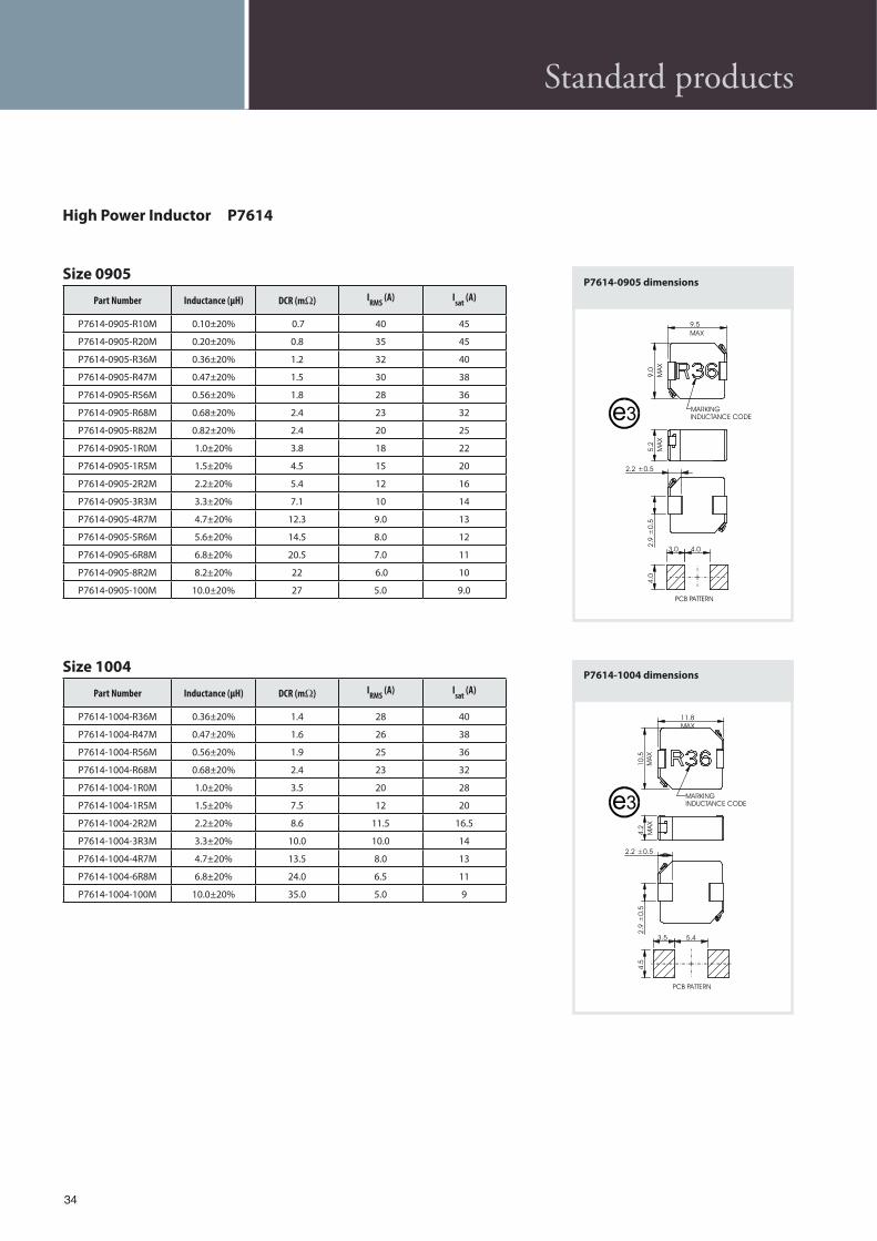
High Power Inductor P7614
Size 0603
Part Number Inductance (µH) DCR (m ) IRMS
(A) Isat
(A)
P7614-0603-R10M 0.10±20% 1.7 32.5 42
P7614-0603-R15M 0.15±20% 2.5 26 38
P7614-0603-R20M 0.20±20% 3.0 24 36
P7614-0603-R22M 0.22±20% 2.8 23 36
P7614-0603-R33M 0.33±20% 3.9 20 30
P7614-0603-R47M 0.47±20% 4.2 17.5 26
P7614-0603-R68M 0.68±20% 5.5 15.5 23
P7614-0603-R82M 0.82±20% 8.0 13 20
P7614-0603-1R0M 1.0±20% 10 11 16
P7614-0603-1R5M 1.5±20% 15 9.0 14
P7614-0603-1R8M 1.8±20% 20 9.0 17
P7614-0603-2R2M 2.2±20% 20 8.0 12
P7614-0603-3R3M 3.3±20% 30 6.0 10
P7614-0603-4R7M 4.7±20% 40 5.5 6.5
P7614-0603-6R8M 6.8±20% 60 4.5 6.0
P7614-0603-8R2M 8.2±20% 68 4.0 5.5
P7614-0603-100M 10±20% 105 3.0 4.5
$e P7614 is a high-energy-density surface mount inductor for high current power converters. $e family handles large transient current spikes without saturation. Inductance values are available as low as 0.1µH.
Components are available in ten mechanical sizes, all offering high energy storage and current handling in very low profile packages.A distributed gap powder core is used, yielding stable inductance at very high currents. $e core material is moulded over the winding and provides a robust, self shielded structure that operates over a wide temperature range.
MA
X
7.0
MAX
7.8
MA
X
3.2
1.6 ±0.5
2.1
±0.5
3.72.5
3.5
MARKINGINDUCTANCE CODE
PCB PATTERN
e3
P7614-0602 dimensions
Size 0602
Part Number Inductance (µH) DCR (m ) IRMS
(A) Isat
(A)
P7614-0602-R10M 0.10±20% 3.5 18 40
P7614-0602-R15M 0.15±20% 5.2 15 28
P7614-0602-R22M 0.22±20% 5.7 14 26
P7614-0602-R33M 0.33±20% 7.0 12 18
P7614-0602-R47M 0.47±20% 9.3 11 18
P7614-0602-R68M 0.68±20% 13.9 9.0 17
P7614-0602-R82M 0.82±20% 15.9 8.0 15
P7614-0602-1R0M 1.0±20% 18 7.0 14
P7614-0602-1R5M 1.5±20% 34 4.0 12
P7614-0602-2R2M 2.2±20% 46 5.0 9.0
P7614-0602-2R5M 2.5±20% 52 3.5 8.0
P7614-0602-3R3M 3.3±20% 60 3.25 7.0
P7614-0602-4R7M 4.7±20% 78 3.0 5.0
P7614-0603 dimensions
MA
X
7.0
MAX
7.8
2.0
1.6 ±0.5
2.1
±0.5
3.72.5
3.5
MARKINGINDUCTANCE CODE
PCB PATTERN
e3
Standard products

33
Standard products
Size 0604
Part Number Inductance (µH) DCR (m ) IRMS
(A) Isat
(A)
P7614-0604-R33M 0.33±20% 1.4 23 32
P7614-0604-R47M 0.47±20% 2.0 20 30
P7614-0604-R68M 0.68±20% 3.8 17 28
P7614-0604-R82M 0.82±20% 5.0 15 24
P7614-0604-1R0M 1.0±20% 7.0 13 20
P7614-0604-1R2M 1.2±20% 8.0 12 18
P7614-0604-1R5M 1.5±20% 10 11 16
P7614-0604-1R8M 1.8±20% 13 10.5 14
P7614-0604-2R2M 2.2±20% 15 10 14
P7614-0604-3R3M 3.3±20% 18 7.0 11
P7614-0604-4R7M 4.7±20% 21 6.0 9.0
P7614-0604-5R6M 5.6±20% 30 5.5 7.0
P7614-0604-6R8M 6.8±20% 32 5.0 7.0
Size 0605
Part Number Inductance (µH) DCR (m ) IRMS
(A) Isat
(A)
P7614-0605-R39M 0.39±20% 2.6 21 30
P7614-0605-R68M 0.68±20% 3.8 18 28
P7614-0605-1R0M 1.0±20% 4.2 15 22
P7614-0605-1R5M 1.5±20% 5.4 16 18
P7614-0605-2R2M 2.2±20% 8.2 13 15
P7614-0605-3R3M 3.3±20% 15.2 10 13
P7614-0605-4R7M 4.7±20% 19 7 10
P7614-0605-6R8M 6.8±20% 30 6 8
P7614-0605-100M 10±20% 45 5 6
P7614-0604 dimensions
MA
X
7.0
MAX
7.8
MA
X
4.2
1.6 ±0.5
2.1
±0.5
3.72.5
3.5
MARKINGINDUCTANCE CODEe3
P7614-0605 dimensions
P7614-0602 P7614-0603 P7614-0604 P7614-0905 P7614-1004
P7614-1005 P7614-1203 P6714-1205
P7614-0605
P7614-1307
e3MARKING
INDUCTANCE CODE
MA
X
7.0
MAX
7.8
MA
X
5.0
1.6 ± 0.5
2.1
±0
.5
3.72.5
3.5
34
High Power Inductor P7614
Size 1004
Part Number Inductance (µH) DCR (m ) IRMS
(A) Isat
(A)
P7614-1004-R36M 0.36±20% 1.4 28 40
P7614-1004-R47M 0.47±20% 1.6 26 38
P7614-1004-R56M 0.56±20% 1.9 25 36
P7614-1004-R68M 0.68±20% 2.4 23 32
P7614-1004-1R0M 1.0±20% 3.5 20 28
P7614-1004-1R5M 1.5±20% 7.5 12 20
P7614-1004-2R2M 2.2±20% 8.6 11.5 16.5
P7614-1004-3R3M 3.3±20% 10.0 10.0 14
P7614-1004-4R7M 4.7±20% 13.5 8.0 13
P7614-1004-6R8M 6.8±20% 24.0 6.5 11
P7614-1004-100M 10.0±20% 35.0 5.0 9
P7614-1004 dimensions
5.43.5
4.5
2.9
±0.5
2.2 ±0.5
MA
X
4.2
10.5
MA
X
11.8
MAX
PCB PATTERN
MARKINGINDUCTANCE CODEe3
Size 0905
Part Number Inductance (µH) DCR (m ) IRMS
(A) Isat
(A)
P7614-0905-R10M 0.10±20% 0.7 40 45
P7614-0905-R20M 0.20±20% 0.8 35 45
P7614-0905-R36M 0.36±20% 1.2 32 40
P7614-0905-R47M 0.47±20% 1.5 30 38
P7614-0905-R56M 0.56±20% 1.8 28 36
P7614-0905-R68M 0.68±20% 2.4 23 32
P7614-0905-R82M 0.82±20% 2.4 20 25
P7614-0905-1R0M 1.0±20% 3.8 18 22
P7614-0905-1R5M 1.5±20% 4.5 15 20
P7614-0905-2R2M 2.2±20% 5.4 12 16
P7614-0905-3R3M 3.3±20% 7.1 10 14
P7614-0905-4R7M 4.7±20% 12.3 9.0 13
P7614-0905-5R6M 5.6±20% 14.5 8.0 12
P7614-0905-6R8M 6.8±20% 20.5 7.0 11
P7614-0905-8R2M 8.2±20% 22 6.0 10
P7614-0905-100M 10.0±20% 27 5.0 9.0
MA
X
9.0
MAX
9.5
MA
X
5.2
2.2 ±0.5
2.9
±0.5
4.03.0
4.0
MARKINGINDUCTANCE CODE
PCB PATTERN
Fig. 4
e3
P7614-0905 dimensions
Standard products

35
Size 1005
Part Number Inductance (µH) DCR (m ) IRMS
(A) Isat
(A)
P7614-1005-R36M 0.36±20% 0.8 35 40
P7614-1005-R47M 0.47±20% 0.9 32 38
P7614-1005-R56M 0.56±20% 1.1 30 36
P7614-1005-R68M 0.68±20% 1.3 29 32
P7614-1005-1R0M 1.0±20% 2.2 24 28
P7614-1005-1R5M 1.5±20% 2.6 20 22
P7614-1005-2R2M 2.2±20% 4.0 17 20
Size 1203
Part Number Inductance (µH) DCR (m ) IRMS
(A) Isat
(A)
P7614-1203-R10M 0.10±20% 0.96 43 56
P7614-1203-R15M 0.15±20% 1.2 41 50
P7614-1203-R22M 0.22±20% 1.3 38.5 50
P7614-1203-R32M 0.33±20% 1.5 36.5 50
P7614-1203-R47M 0.47±20% 2.0 32 44
P7614-1203-R60M 0.60±20% 2.5 29 42
P7614-1203-R68M 0.68±20% 2.5 28 40
P7614-1203-R82M 0.82±20% 3.0 25 38
P7614-1203-1R0M 1.0±20% 3.5 24 36
P7614-1203-1R5M 1.5±20% 5.5 19 28
P7614-1203-1R8M 1.8±20% 7.0 16.5 24
P7614-1203-2R2M 2.2±20% 8.0 16 20
P7614-1203-3R3M 3.3±20% 12 12 18
P7614-1203-4R7M 4.7±20% 15 10 16
P7614-1203-5R6M 5.6±20% 18 10 14
P7614-1203-6R8M 6.8±20% 22 9.0 13
P7614-1203-8R2M 8.2±20% 28 8.5 12
P7614-1203-100M 10.0±20% 34 7.0 9.5
MA
X
10.5
MAX
11.8
MA
X
4.8
2.2 ±0.5
2.9
±0.5
5.43.5
4.5
MARKINGINDUCTANCE CODE
PCB PATTERN
Fig. 6
e3
P7614-1005 dimensions
P7614-1203 dimensionsFig. 7
4.5
4.0 7.0
3.0
±0.5
2.5 ±0.5
MA
X
3.7
13.9
MAX
13.5
MA
X
PCB PATTERN
MARKINGINDUCTANCE CODEe3
Standard products

36
Size 1205
Part Number Inductance (µH) DCR (m ) IRMS
(A) Isat
(A)
P7614-1205-R36M 0.36±20% 1.1 41 75
P7614-1205-R47M 0.47±20% 1.3 38 65
P7614-1205-R56M 0.56±20% 1.5 36 55
P7614-1205-R68M 0.68±20% 1.7 34 54
P7614-1205-1R0M 1.0±20% 2.5 29 50
P7614-1205-1R5M 1.5±20% 4.1 23 48
P7614-1205-2R2M 2.2±20% 5.5 20 32
P7614-1205-3R3M 3.3±20% 9.2 15 32
P7614-1205-4R7M 4.7±20% 15 16 27
P7614-1205-6R8M 6.8±20% 18 13 21
P7614-1205-8R2M 8.2±20% 14 9.5 18
P7614-1205-100M 10.0±20% 18 9.0 16
P7614-1205-120M 12.0±20% 18 7.5 10
Size 1307
Part Number Inductance (µH) DCR (m ) IRMS
(A) Isat
(A)
P7614-1307-R47M 0.47±20% 1.2 41 65
P7614-1307-R68M 0.68±20% 1.6 35 60
P7614-1307-1R0M 1.0±20% 2.1 32 50
P7614-1307-1R5M 1.5±20% 2.6 27 48
P7614-1307-2R2M 2.2±20% 4.2 22 40
P7614-1307-3R3M 3.3±20% 6.8 18 35
P7614-1307-4R7M 4.7±20% 11.2 15 30
P7614-1307-6R8M 6.8±20% 14 12 21
P7614-1307-100M 10.0±20% 17 10 16
P7614-1205 dimensions
4.5
4.0 7.0
MA
X
5.2
13.9
MAX
13.5
MA
X
PCB PATTERN
MARKINGINDUCTANCE CODE
3.0
±0.5
2.5 ±0.5
e3
Fig. 8
High Power Inductor P7614
P7614-1307 dimensions
Fig. 10
e3 MARKING
INDUCTANCE CODE
PCB PATTERN
MA
X
13.7
MAX
13.7
MA
X
7.0
2.5 ± 0.5
3.0
±0
.5
8.03.0
3.4
Standard products

37
Notes

38
Notes

39
ETAL Group AB – Sweden
Vällingby (Head o&ce)
Box 39162 11 VällingbySwedenVisiting address: Grimstagatan 160 Phone: +46 8 759 35 00 Fax: +46 8 759 35 40E-mail: [email protected] E-mail: [email protected]
ETAL Group Oy – Finland
Höyläämötie 3BBox 89FIN-00380 Helsinki FinlandPhone: +358 9 7510 3500Fax: +358 9 7510 3599E-mail: [email protected]: [email protected]
ETAL (UK) Limited
Luna Place
Dundee Technology ParkDundeeDD2 1XZU.K.Phone: +44 1382 561561Fax: +44 1382 561144E-mail: [email protected] E-mail: [email protected]
EG (Shanghai) Commercial Co., Ltd – China
Room 1808Shenshi BuildingNo. 511, Weihai RoadShanghai 200041 ChinaPhone: +86 21 5213 0077Fax: +86 21 5213 3152 E-mail: [email protected]: [email protected]
Representatives and distributors
ETAL operates a worldwide distribution network. $ese distribution partners assist ETAL’s in-house sales department and support our customers’ designers and buyers.
To find your local ETAL Group distributor or representative visit our website
www.etalgroup.com
Sales offices

40
© E
TAL
Gro
up
AB
ETAL Group is a leading supplier of inductive components for the telecom, automotive
and electronics industry. The Group designs quali#ed electronic transformers in Finland,
Sweden and the UK to a world wide market. Manufacturing is carried out in south eastern
Asia and in Europe. The Group also has its own sales oJces in Sweden, Finland, the UK and
China and a world wide distribution network.
ElektronikGruppen is one of the Nordic region’s leading suppliers of high-tech electronic
components, systems and production equipment for the electronics industry. Operations
are conducted in three business areas based on specialized knowledge in electronics and
electromechanics. The Nordic region is the home market but ElektronikGruppen is also
established in the Baltic countries, Poland, Germany, the UK, China and Sri Lanka. The share
is listed on the OMX Nordic Exchange Stockholm.


