Produced Water Society Conference 2011 1 PARC Hardware Systems Laboratory Innovative Technology for BTEX Removal from Produced Water M.H. Lean, H.B. Hsieh, J. Seo, N. Chang, A. Kole, A.R. Völkel, and K. Melde Palo Alto Research Center, Palo Alto, California, USA 94304, [email protected]Keywords Hydrodynamic separation, VOC, PAH, BTEX, ACP, adsorption, neutrally buoyant particles, TSS, spectrophotometry Abstract This paper describes a two-step approach incorporating a front-end activated carbon reactor and a back-end hydrodynamic separator to continuously remove benzene, toluene, ethylbenzene, and xylene (BTEX) from produced water without using a filtration barrier. The flow through treatment train includes the following steps: (1) volume dispersal of activated carbon particles (ACP) into incoming raw produced water; (2) agitating the mixture with sufficient detention time in the reactor for adsorption of BTEX; and (3) recovering the ACP using a novel hydrodynamic separator. The ACP may be recycled for reuse by conventional regeneration methods. Proof-of-concept results show high removal efficiencies of volatile hydrocarbon (VOC) components and recovery of ACP. Introduction Produced water from the oil and gas industry contains solids (sand, silt), dissolved minerals, traces of heavy metals, suspended oil (non-polar), bacteria and dissolved organics (including hydrocarbons), and production chemicals (corrosion inhibitors, oxygen scavengers, scale inhibitors, emulsion breakers and clarifiers, coagulants and flocculants, and solvents) [1]. This complex fluid needs to be treated before disposal into deep wells or reinjection to maintain well pressure. The water-cut increases as the well ages to the high 90% range. The TDS is several times that for seawater and poses severe clogging problems when the supersaturated produced water reacts to form precipitates with decreasing surface pressure and temperature. On-shore and off-shore produced water have different treatment requirements and challenges. Conventional methods include gravity-based separation (flotation), filtration, and cyclonic separation. While adequate, the technology suite suffers from a combination of low efficiency, long treatment times, large footprint, high labor demand, multiple treatment steps, high energy, and high cost. For on- shore, the lack of in situ treatment options result in tens of billions in trucking costs just in the United States alone. For off-shore platforms, the increasing legislation for discharge standards drives a need for innovation for produced water treatment. Dissolved VOC is a class of aromatics that include BTEX, NPD (naphthalene, phenanthrene, and dibenzothiophene), and PAH (polycyclic aromatic compounds represented by the 16 EPA PAH). The environmental effects include a number of toxicity mechanisms [2]. Current technologies to reduce or remove dissolved aromatic hydrocarbons are considered as tertiary polishing steps following behind more traditional methods of dispersed oil removal. Technologies especially for BTEX removal include: adsorption, membranes, steam stripping, and biological aerobic degradation. Adsorption media include activated carbon, alumina, zeolite, and macroporous polymer extraction. In this paper, a novel technology is presented that can significantly impact produced water treatment in a disruptive way. The focus of this paper will be on removal of BTEX but it appears
Transcript
Produced Water Society Conference 2011 1
PARC Hardware Systems Laboratory
Innovative Technology for BTEX Removal from Produce d Water
M.H. Lean, H.B. Hsieh, J. Seo, N. Chang, A. Kole, A .R. Völkel, and K. Melde
Palo Alto Research Center, Palo Alto, California, USA 94304, [email protected] Keywords Hydrodynamic separation, VOC, PAH, BTEX, ACP, adsorption, neutrally buoyant particles, TSS, spectrophotometry Abstract This paper describes a two-step approach incorporating a front-end activated carbon reactor and a back-end hydrodynamic separator to continuously remove benzene, toluene, ethylbenzene, and xylene (BTEX) from produced water without using a filtration barrier. The flow through treatment train includes the following steps: (1) volume dispersal of activated carbon particles (ACP) into incoming raw produced water; (2) agitating the mixture with sufficient detention time in the reactor for adsorption of BTEX; and (3) recovering the ACP using a novel hydrodynamic separator. The ACP may be recycled for reuse by conventional regeneration methods. Proof-of-concept results show high removal efficiencies of volatile hydrocarbon (VOC) components and recovery of ACP. Introduction Produced water from the oil and gas industry contains solids (sand, silt), dissolved minerals, traces of heavy metals, suspended oil (non-polar), bacteria and dissolved organics (including hydrocarbons), and production chemicals (corrosion inhibitors, oxygen scavengers, scale inhibitors, emulsion breakers and clarifiers, coagulants and flocculants, and solvents) [1]. This complex fluid needs to be treated before disposal into deep wells or reinjection to maintain well pressure. The water-cut increases as the well ages to the high 90% range. The TDS is several times that for seawater and poses severe clogging problems when the supersaturated produced water reacts to form precipitates with decreasing surface pressure and temperature. On-shore and off-shore produced water have different treatment requirements and challenges. Conventional methods include gravity-based separation (flotation), filtration, and cyclonic separation. While adequate, the technology suite suffers from a combination of low efficiency, long treatment times, large footprint, high labor demand, multiple treatment steps, high energy, and high cost. For on-shore, the lack of in situ treatment options result in tens of billions in trucking costs just in the United States alone. For off-shore platforms, the increasing legislation for discharge standards drives a need for innovation for produced water treatment. Dissolved VOC is a class of aromatics that include BTEX, NPD (naphthalene, phenanthrene, and dibenzothiophene), and PAH (polycyclic aromatic compounds represented by the 16 EPA PAH). The environmental effects include a number of toxicity mechanisms [2]. Current technologies to reduce or remove dissolved aromatic hydrocarbons are considered as tertiary polishing steps following behind more traditional methods of dispersed oil removal. Technologies especially for BTEX removal include: adsorption, membranes, steam stripping, and biological aerobic degradation. Adsorption media include activated carbon, alumina, zeolite, and macroporous polymer extraction. In this paper, a novel technology is presented that can significantly impact produced water treatment in a disruptive way. The focus of this paper will be on removal of BTEX but it appears
Produced Water Society Conference 2011 2
PARC Hardware Systems Laboratory
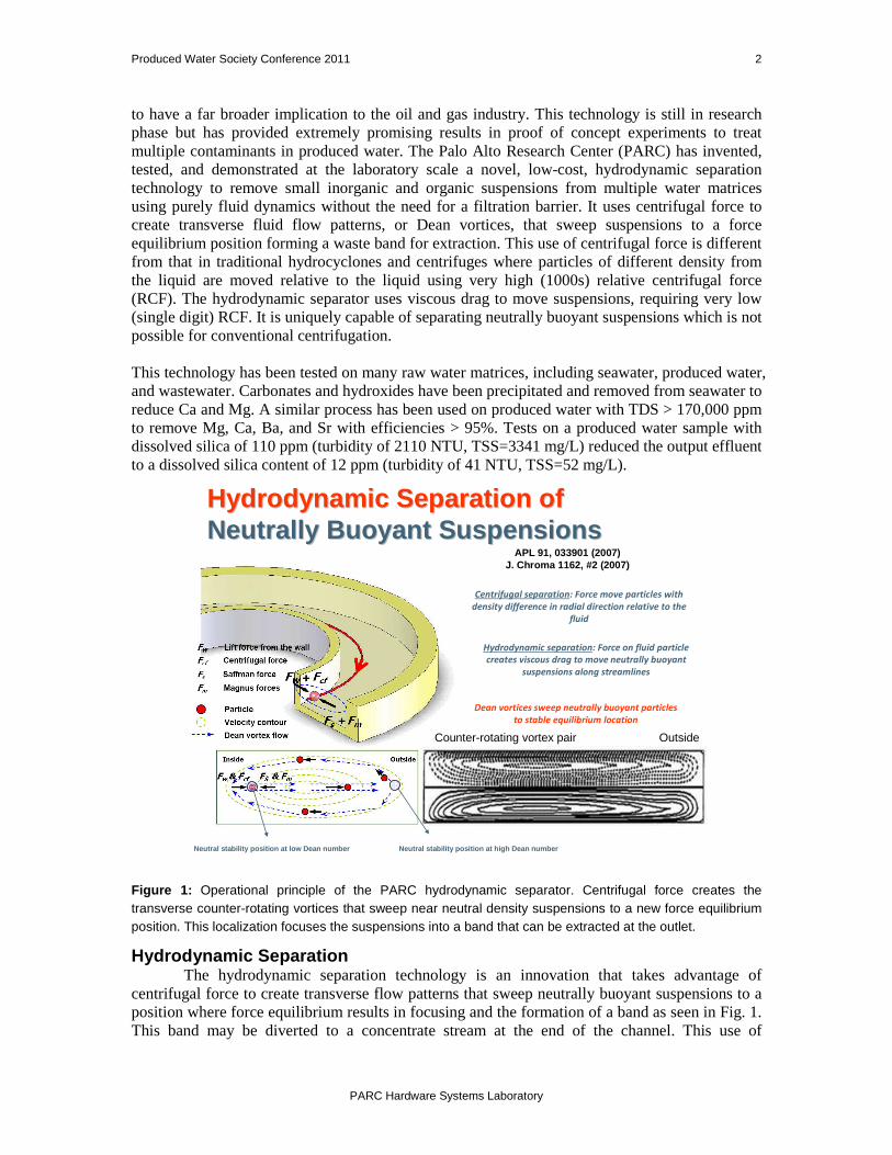
to have a far broader implication to the oil and gas industry. This technology is still in research phase but has provided extremely promising results in proof of concept experiments to treat multiple contaminants in produced water. The Palo Alto Research Center (PARC) has invented, tested, and demonstrated at the laboratory scale a novel, low-cost, hydrodynamic separation technology to remove small inorganic and organic suspensions from multiple water matrices using purely fluid dynamics without the need for a filtration barrier. It uses centrifugal force to create transverse fluid flow patterns, or Dean vortices, that sweep suspensions to a force equilibrium position forming a waste band for extraction. This use of centrifugal force is different from that in traditional hydrocyclones and centrifuges where particles of different density from the liquid are moved relative to the liquid using very high (1000s) relative centrifugal force (RCF). The hydrodynamic separator uses viscous drag to move suspensions, requiring very low (single digit) RCF. It is uniquely capable of separating neutrally buoyant suspensions which is not possible for conventional centrifugation. This technology has been tested on many raw water matrices, including seawater, produced water, and wastewater. Carbonates and hydroxides have been precipitated and removed from seawater to reduce Ca and Mg. A similar process has been used on produced water with TDS > 170,000 ppm to remove Mg, Ca, Ba, and Sr with efficiencies > 95%. Tests on a produced water sample with dissolved silica of 110 ppm (turbidity of 2110 NTU, TSS=3341 mg/L) reduced the output effluent to a dissolved silica content of 12 ppm (turbidity of 41 NTU, TSS=52 mg/L).
density difference in radial direction relative to the
fluid
Neutral stability position at low Dean number Neutra l stability position at high Dean number
APL 91, 033901 (2007)J. Chroma 1162, #2 (2007)
OutsideCounter-rotating vortex pair
Figure 1: Operational principle of the PARC hydrodynamic separator. Centrifugal force creates the transverse counter-rotating vortices that sweep near neutral density suspensions to a new force equilibrium position. This localization focuses the suspensions into a band that can be extracted at the outlet.
Hydrodynamic Separation The hydrodynamic separation technology is an innovation that takes advantage of centrifugal force to create transverse flow patterns that sweep neutrally buoyant suspensions to a position where force equilibrium results in focusing and the formation of a band as seen in Fig. 1. This band may be diverted to a concentrate stream at the end of the channel. This use of
Produced Water Society Conference 2011 3
PARC Hardware Systems Laboratory
centrifugal force is different from traditional hydrocyclones and centrifuges where particles of different density from the liquid are moved relative to the liquid using very high (1000s) relative centrifugal force (RCF). The RCF in our device is in single digits (<2), and is the main reason for the low power requirement. Suspensions with density differences are also separated. Other salient features include: no moving parts, scalability, small foot print, continuous flow operation, filter-less, low maintenance, and modular construction. More details are contained in the referenced literature [3-7]. Removal of Produced Water Contaminants The hydrodynamic separator together with a pre-conditioning step allows for the continuous flow removal of most of the target contaminants without the need for a filtration barrier. Application scenarios for the oil and gas industry include: � Oil-from-water separation achieved by the use of an agitator to create dispersions with oil
materials such as activated carbon particles (ACP) or activated alumina (AA). These particles may then be hydrodynamically separated for recovery, regeneration, and reuse (Fig. 2).
� Conventional lime softening and/or soda ash or pearl ash chemistry adapted to precipitate dissolved contaminants such as salts and multi-valent metals for downstream hydrodynamic separation.
� Inorganic and organic suspended solids, especially those with near neutral buoyancy, removed directly by the hydrodynamic separator. Smaller sub-micron solids may be coagulated and flocculated into larger aggregates prior to removal. Coagulation and flocculation also remove some dissolved contaminants through chemisorption, complexation, and/or incorporation into microstructures. The unique ability to address neutrally buoyant suspensions allows direct removal of micro-organisms without compromising their viability.
Collectively, this suite of capabilities allow for comprehensive treatment of produced water which changes its property as a function of chemical effects, well age, and geological locality.
Figure 2 : Treatment train for dispersion, adsorption, and recovery of ACP using hydrodynamic separation. The ACP can then be re-injected multiple times before being taken off-line for regeneration. Sample Results for Removal of BTEX The process train for removal of dissolved contaminants is under continued development. The proof-of-concept results that follow are derived using an available research prototype with performance close to the characterized sample. Therefore, conditions may be further optimized to derive even better performance than are reported here.
ACP Separator
Effluent – mostly water
below spec ppm
Waste – ACP and
adsorbed BTEX and other
contaminants
Raw produced water effluent from primary
equalization tank
ACP Reactor
Regenerate ACP
Produced Water Society Conference 2011 4
PARC Hardware Systems Laboratory
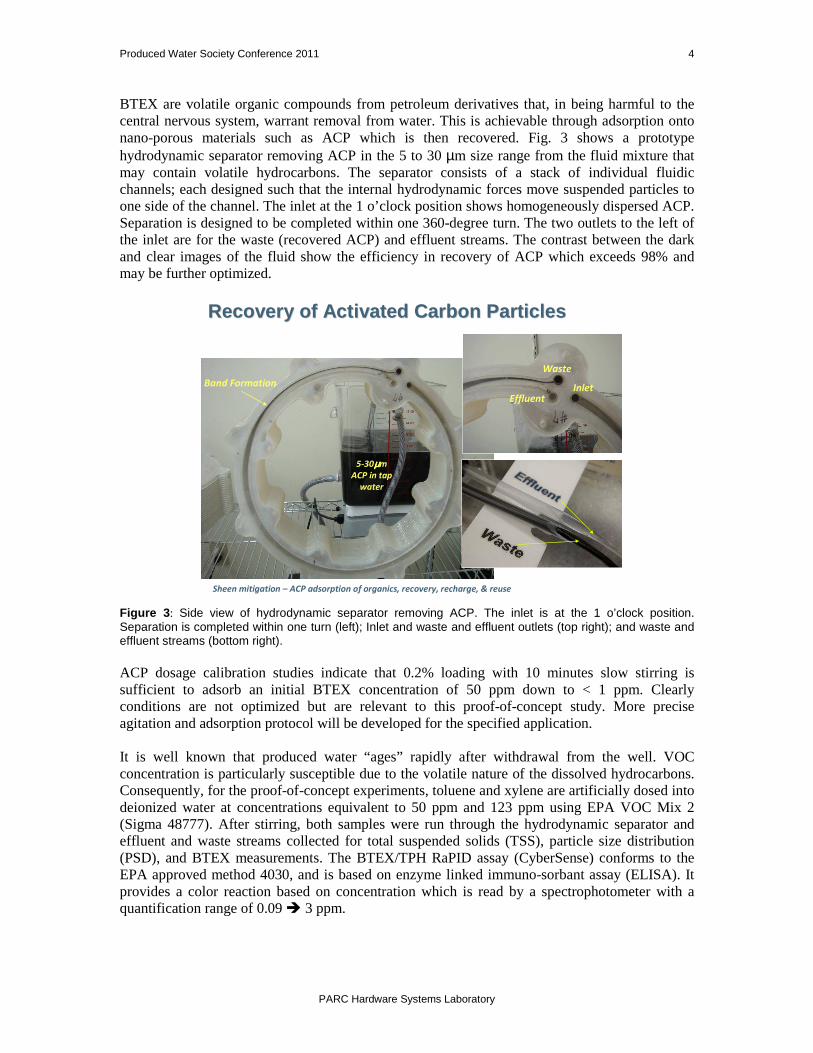
BTEX are volatile organic compounds from petroleum derivatives that, in being harmful to the central nervous system, warrant removal from water. This is achievable through adsorption onto nano-porous materials such as ACP which is then recovered. Fig. 3 shows a prototype hydrodynamic separator removing ACP in the 5 to 30 µm size range from the fluid mixture that may contain volatile hydrocarbons. The separator consists of a stack of individual fluidic channels; each designed such that the internal hydrodynamic forces move suspended particles to one side of the channel. The inlet at the 1 o’clock position shows homogeneously dispersed ACP. Separation is designed to be completed within one 360-degree turn. The two outlets to the left of the inlet are for the waste (recovered ACP) and effluent streams. The contrast between the dark and clear images of the fluid show the efficiency in recovery of ACP which exceeds 98% and may be further optimized.
Recovery of Activated Carbon ParticlesRecovery of Activated Carbon Particles
Figure 3 : Side view of hydrodynamic separator removing ACP. The inlet is at the 1 o’clock position. Separation is completed within one turn (left); Inlet and waste and effluent outlets (top right); and waste and effluent streams (bottom right). ACP dosage calibration studies indicate that 0.2% loading with 10 minutes slow stirring is sufficient to adsorb an initial BTEX concentration of 50 ppm down to < 1 ppm. Clearly conditions are not optimized but are relevant to this proof-of-concept study. More precise agitation and adsorption protocol will be developed for the specified application. It is well known that produced water “ages” rapidly after withdrawal from the well. VOC concentration is particularly susceptible due to the volatile nature of the dissolved hydrocarbons. Consequently, for the proof-of-concept experiments, toluene and xylene are artificially dosed into deionized water at concentrations equivalent to 50 ppm and 123 ppm using EPA VOC Mix 2 (Sigma 48777). After stirring, both samples were run through the hydrodynamic separator and effluent and waste streams collected for total suspended solids (TSS), particle size distribution (PSD), and BTEX measurements. The BTEX/TPH RaPID assay (CyberSense) conforms to the EPA approved method 4030, and is based on enzyme linked immuno-sorbant assay (ELISA). It provides a color reaction based on concentration which is read by a spectrophotometer with a quantification range of 0.09 � 3 ppm.
Produced Water Society Conference 2011 5
PARC Hardware Systems Laboratory
The left image in Fig. 4 shows beakers with dispersed ACP being agitated to promote BTEX adsorption. The separator used is shown in the right image.
Figure 4: Volume dispersed ACP being agitated to adsorb BTEX (left). The single-channel hydrodynamic separator setup (right) shows inlet and two outlets. Shown in the right side of Fig. 5 is an image from the TSS analysis of ACP on the 0.45 µm filters from the effluent and waste streams. On the left are particle size distributions from laser scattering measurements of the input sample, effluent, and waste streams. The normalized PSD measurements are for the ACP used for the two BTEX test concentrations of 50 and 123 ppm. Recovered ACP by volume is 98.9% and 97.7%, respectively.
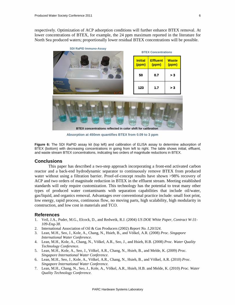
Figure 5: TSS of effluent and waste streams of the two BTEX test samples showing ACP dispersed in the beakers and capture on 0.45µm filters (right), and normalized PSD of the ACP by volume showing recovery efficiencies > 98%. The top left image in Fig. 6 shows the RaPID assay kit used to quantify BTEX concentration. The lower image shows the calibration vials for the spectrophotometer measurements with the expected color shift in deceasing BTEX concentration in going from left to right. The table shows the corresponding BTEX concentrations with two orders of magnitude reduction by adsorption. The 50 ppm and 123 ppm samples show residual concentrations of 0.7 ppm and 1.7 ppm,
-2
0
2
4
6
8
10
12
14
1 10 100 1000
Vo
lum
e s
ep
ara
tio
n(%
)
particle size(micron)
Sample(Cal) Effluent Waste
Effluent and Waste TSS Measurement
-5
0
5
10
15
20
25
1 10 100 1000
Vo
lum
e s
ep
ara
tio
n(%
)
particle size(micron)
Sample(Cal) Effluent Waste
Effluent 1.2% of Sample 21.35 ppm
Input
sample
100%
Waste
98.8% of Sample
1838.04 ppm
Effluent 2.3% of Sample 35.07 ppm
Input sample
100%
Waste
97.7% of Sample
1507.50 ppm
BTEX sample: 50 ppm
BTEX Sample: 123 p pm
ACP Sample: 0.2% vol
Effluent stream samples
Concentrate stream samples
BTEX Adsorption ACP Separato r
Produced Water Society Conference 2011 6
PARC Hardware Systems Laboratory
respectively. Optimization of ACP adsorption conditions will further enhance BTEX removal. At lower concentrations of BTEX, for example, the 24 ppm maximum reported in the literature for North Sea produced waters; proportionally lower residual BTEX concentrations will be possible.
Figure 6: The SDI RaPID assay kit (top left) and calibration of ELISA assay to determine adsorption of BTEX (bottom) with decreasing concentrations in going from left to right. The table shows initial, effluent, and waste stream BTEX concentrations, indicating two orders of magnitude reductions in BTEX. Conclusions
This paper has described a two-step approach incorporating a front-end activated carbon reactor and a back-end hydrodynamic separator to continuously remove BTEX from produced water without using a filtration barrier. Proof-of-concept results have shown >98% recovery of ACP and two orders of magnitude reduction in BTEX in the effluent stream. Meeting established standards will only require customization. This technology has the potential to treat many other types of produced water contaminants with separation capabilities that include oil/water, gas/liquid, and organics removal. Advantages over conventional practice include: small foot print, low energy, rapid process, continuous flow, no moving parts, high scalability, high modularity in construction, and low cost in materials and TCO. References 1. Veil, J.A., Puder, M.G., Elcock, D., and Redweik, R.J. (2004) US DOE White Paper, Contract W-31-
109-Eng-38. 2. International Association of Oil & Gas Producers (2002) Report No. I.20/324. 3. Lean, M.H., Seo, J., Kole, A., Chang, N., Hsieh, B., and Völkel, A.R. (2008) Proc. Singapore
International Water Conference. 4. Lean, M.H., Kole, A., Chang, N., Völkel, A.R., Seo, J., and Hsieh, H.B. (2008) Proc. Water Quality
Technology Conference. 5. Lean, M.H., Kole, A., Seo, J., Völkel, A.R., Chang, N., Hsieh, B., and Melde, K. (2009) Proc.
Singapore International Water Conference. 6. Lean, M.H., Seo, J., Kole, A., Völkel, A.R., Chang, N., Hsieh, B., and Völkel, A.R. (2010) Proc.
Singapore International Water Conference. 7. Lean, M.H., Chang, N., Seo, J., Kole, A., Völkel, A.R., Hsieh, H.B. and Melde, K. (2010) Proc. Water
Quality Technology Conference.
SDI RaPID Immuno-Assay
BTEX concentrations reflected in color shift for ca libration
Absorption at 450nm quantifies BTEX from 0.09 to 3 ppm