17
Input-Output Modules - 2017 WattsIndustries.co.uk Electro Controls

Input-Output Modules - 2017
WattsIndustries.co.uk
Electro Controls
[email protected] \ wattsindustries.co.uk
B.M.S InPUT - OUTPUT MODULES SInGLE AnD ADJUSTABLE rELAY
InPUT-OUTPUT MODULES SECTION 08
ESRM..
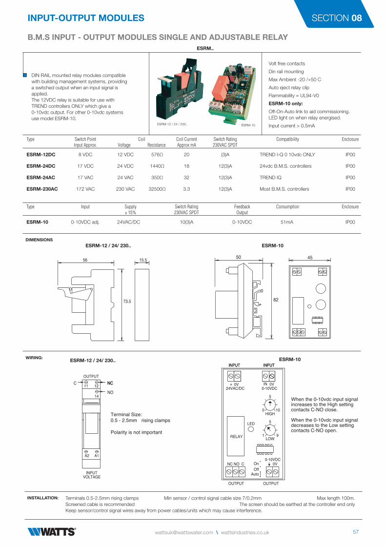
DIN RAIL mounted relay modules compatiblewith building management systems, providinga switched output when an input signal isapplied.The 12VDC relay is suitable for use withTREND controllers ONLY which give a0-10vdc output. For other 0-10vdc systemsuse model ESRM-10.
Volt free contacts
Din rail mounting
Max Ambient -20 /+50 C
Auto eject relay clip
Flammability = UL94-V0
ESRM-10 only:
Off-On-Auto link to aid commissioning. LED light on when relay energised.
Input current > 0.5mA
Type Switch Point Coil Coil Current Switch Rating Compatibility Enclosure Input Approx. Voltage Resistance Approx mA 230VAC SPDT
ESRM-12DC 8 VDC 12 VDC 576Ω 20 (3)A TREND I-Q 0 10vdc ONLY IP00
ESRM-24DC 17 VDC 24 VDC 1440Ω 18 12(3)A 24vdc B.M.S. controllers IP00
ESRM-24AC 17 VAC 24 VAC 350Ω 32 12(3)A TREND IQ IP00
ESRM-230AC 172 VAC 230 VAC 32500Ω 3.3 12(3)A Most B.M.S. controllers IP00
DIMENSIONSESRM-12 / 24/ 230.. ESRM-10
WIRING:
INSTALLATION: Terminals 0.5-2.5mm rising clamps Min sensor / control signal cable size 7/0.2mm Max length 100m.Screened cable is recommended The screen should be earthed at the controller end onlyKeep sensor/control signal wires away from power cables/units which may cause interference.
ESRM-12 / 24 / 230.. ESRM-10
Type Input Supply Switch Rating Feedback Consumption Enclosure ± 15% 230VAC SPDT Output
ESRM-10 0-10VDC adj. 24VAC/DC 10(3)A 0-10VDC 51mA IP00
73.5
56 15.5
82
50 45
ESRM-12 / 24/ 230.. ESRM-10
NO
NCNC
A2 A1
VOLTAGE INPUT
14
11 12
OUTPUTC
Terminal Size:0.5 - 2.5mm rising clamps
Polarity is not important
OUTPUTOUTPUT
24VAC/DC
INPUTINPUT
0V0-10VDC
0V0-10VDC
NC NO C
RELAY
LED
AutoOffOn
INPUTINPUT
+ 0V IN
When the 0-10vdc input signal increases to the High setting contacts C-NO close.
When the 0-10vdc input signal decreases to the Low settingcontacts C-NO open.
5
100
5
LOW
HIGH
91
58 T: +44 (0) 1480 407074 \ F: +44 (0) 1480 407076
InPUT-OUTPUT MODULES
B.M.S rELAY OVErrIDE MODULE 1 - 4 X 0-10VDC InPUTS 4 rELAY OUTPUTSEROV4
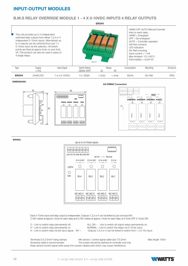
This unit provides up to 4 independentswitched relay outputs from either 1,2,3 or 4independent 0-10vdc inputs. Alternatively upto 4 outputs can be switched from just 1 x0-10vdc input via link selection. All switchpoints are fixed at approx 5vdc on and 4vdcoff. This product can also be used in place of4 single relays.
HAND-OFF-AUTO Manual Overridelinks on each relay: -HAND = EnergisedOFF = De-energisedAUTO = Controller operatedVolt free contactsLED indicationDin-Rail mountingInput current > 1 mAMax Ambient -10 /+50°CFlammability = UL94-V0
Type Supply Input Signal Switch Rating Relays Consumption Mounting Enclosure +-15% 230VAC SPDT On Off
EROV4 24VAC/DC 1-4 x 0-10VDC 4 x 10(3)A > 5vdc < 4vdc 60mA Din Rail IP00
DIMENSIONS:
WIRING:
Each 0-10vdc input and relay output is independent. Outputs 1,2,3 or 4 can be linked to just one input IN1.C-NO makes at approx >5vdc for each relay and C-NC makes at approx <4vdc for each relay. ie 0-4vdc OFF 5-10vdc ON.
O – Link to switch relay permanently off. ALL ON – Link to switch all output relays permanently on.H – Link to switch relay permanently on. NORMAL – Link to switch the relays via 0-10vdc input.A – Link to switch relay via the input signal. IN1 – Outputs 1,2,3 or 4 can be linked to switch from 1 x 0-10v input.
Terminals 0.5-2.5mm² rising clamps Min sensor / control signal cable size 7/0.2mm Max length 100mScreened cable is recommended The screen should be earthed at controller end onlyKeep sensor/control signal wires away from power cables/units which may cause interference.
EROV4
50
82
80
AX-ORM4C Connection
ALL ON NORMAL24V 0V 0V IN4 IN3 IN2 IN1
NC NO C NC NO C NC NO C NC NO C
Rel
ay 1
Rel
ay 2
Rel
ay 3
Rel
ay 4
Pow
er O
N
O H A - IN1 O H A - IN1 O H A - IN1 O H A
NC NO C NC NO C NC NO C NC NO C
RL1RL2RL3RL4ON
LED's
O H A IN1 O H A IN1 O H A IN1 O H A
NormalAll On
Up to 4 x 0-10vdc inputs
24V 0V 0V IN4 IN3 IN2 IN1
[email protected] \ wattsindustries.co.uk
B.M.S InPUT OUTPUT MODULES 2 STAGE rELAY, rAISE - LOWEr, HIGH LOW 0-10VDC
InPUT-OUTPUT MODULES SECTION 08
E2RM..
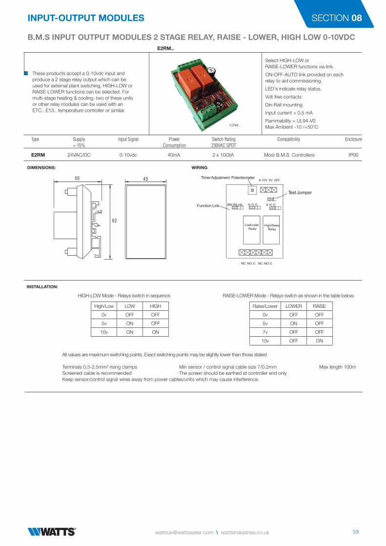
These products accept a 0-10vdc input andproduce a 2 stage relay output which can beused for external plant switching. HIGH-LOW orRAISE-LOWER functions can be selected. Formulti-stage heating & cooling, two of these unitsor other relay modules can be used with anETC.. E13.. temperature controller or similar.
Select HIGH-LOW or RAISE-LOWER functions via link.
ON-OFF-AUTO link provided on each relay to aid commissioning.
LED's indicate relay status.
Volt free contacts
Din-Rail mounting
Input current > 0.5 mA
Flammability = UL94-V0 Max Ambient -10 /+50°C
Type Supply Input Signal Power Switch Rating Compatibility Enclosure +-15% Consumption 230VAC SPDT
E2RM 24VAC/DC 0-10vdc 40mA 2 x 10(3)A Most B.M.S. Controllers IP00
DIMENSIONS:
INSTALLATION:
All values are maximum switching points. Exact switching points may be slightly lower than those stated
Terminals 0.5-2.5mm² rising clamps Min sensor / control signal cable size 7/0.2mm Max length 100mScreened cable is recommended The screen should be earthed at controller end onlyKeep sensor/control signal wires away from power cables/units which may cause interference.
E2RM..
82
50 45
WIRING
BIN R/L H/L A H O A H O
Timer Adjustment Potentiometer
NC NO C NC NO C
Test Jumper
High/Raise
Relay
Low/Lower
Relay
Function Link
0-10V 0V 24V
HIGH-LOW Mode - Relays switch in sequence. RAISE-LOWER Mode - Relays switch as shown in the table below.
High/Low LOW HIGH
0v OFF OFF
5v ON OFF
10v ON ON
Raise/Lower LOWER RAISE
0v OFF OFF
5v ON OFF
7v OFF OFF
10v OFF ON
60 T: +44 (0) 1480 407074 \ F: +44 (0) 1480 407076
InPUT-OUTPUT MODULES
B.M.S InPUT - OUTPUT MODULES 3 STAGE rELAY, SEQUEnCE, BInArY 0-10VDCE3RMT..
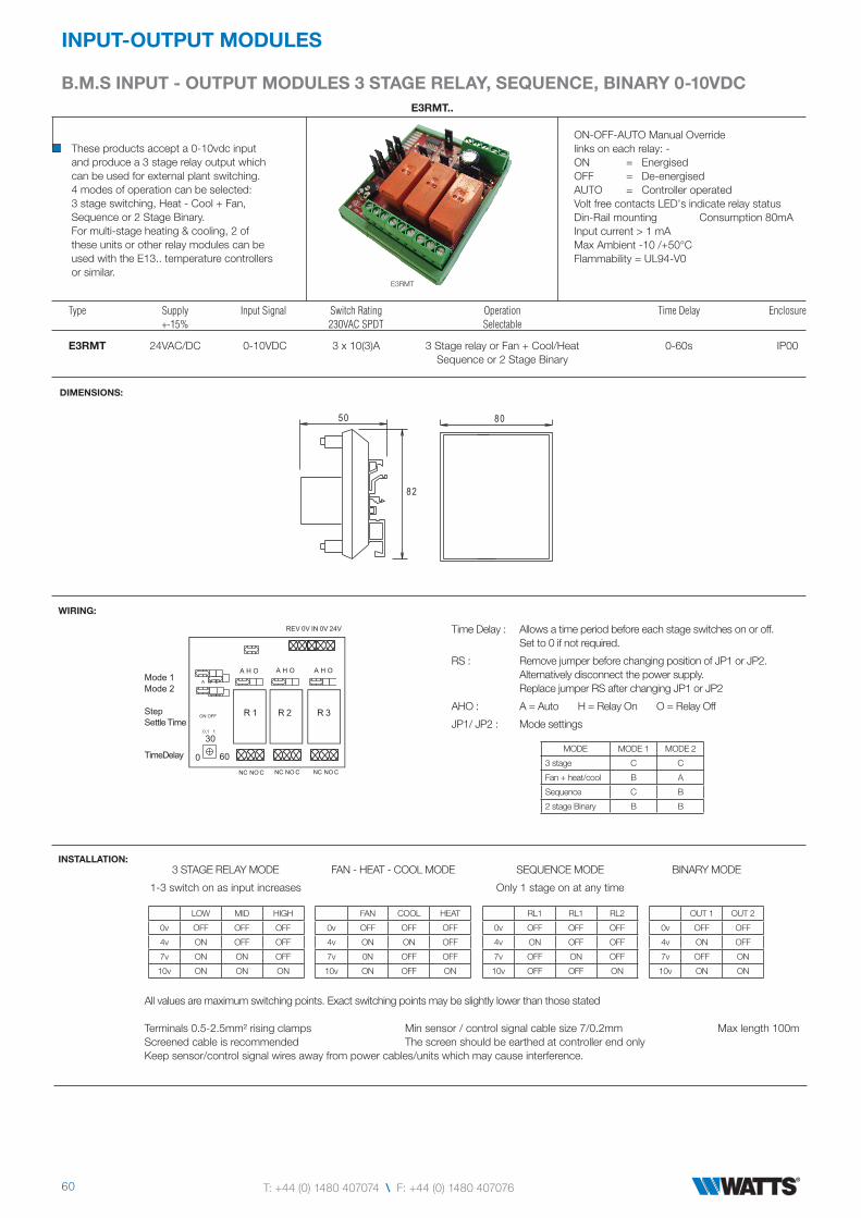
These products accept a 0-10vdc inputand produce a 3 stage relay output whichcan be used for external plant switching.4 modes of operation can be selected:3 stage switching, Heat - Cool + Fan,Sequence or 2 Stage Binary.For multi-stage heating & cooling, 2 ofthese units or other relay modules can beused with the E13.. temperature controllersor similar.
ON-OFF-AUTO Manual Overridelinks on each relay: -ON = EnergisedOFF = De-energisedAUTO = Controller operatedVolt free contacts LED's indicate relay statusDin-Rail mounting Consumption 80mAInput current > 1 mAMax Ambient -10 /+50°CFlammability = UL94-V0
Type Supply Input Signal Switch Rating Operation Time Delay Enclosure +-15% 230VAC SPDT Selectable
E3RMT 24VAC/DC 0-10VDC 3 x 10(3)A 3 Stage relay or Fan + Cool/Heat 0-60s IP00 Sequence or 2 Stage Binary
DIMENSIONS:
WIRING:
All values are maximum switching points. Exact switching points may be slightly lower than those stated
Terminals 0.5-2.5mm² rising clamps Min sensor / control signal cable size 7/0.2mm Max length 100mScreened cable is recommended The screen should be earthed at controller end onlyKeep sensor/control signal wires away from power cables/units which may cause interference.
E3RMT
MODE MODE 1 MODE 2
3 stage C C
Fan + heat/cool B A
Sequence C B
2 stage Binary B B
3 STAGE RELAY MODE
1-3 switch on as input increases
50
82
80
REV 0V IN 0V 24V
A H O A H O A H O
R 1 R 2 R 3
NC NO C NC NO C NC NO C
Mode 1
Mode 2
Step
Settle Time
TimeDelay
ON OFF
0.1 1
30
0 60
A B C
Time Delay : Allows a time period before each stage switches on or off. Set to 0 if not required.
RS : Remove jumper before changing position of JP1 or JP2.Alternatively disconnect the power supply. Replace jumper RS after changing JP1 or JP2
AHO : A = Auto H = Relay On O = Relay Off
JP1/ JP2 : Mode settings
INSTALLATION:FAN - HEAT - COOL MODE BINARY MODESEQUENCE MODE
Only 1 stage on at any time
LOW MID HIGH
0v OFF OFF OFF
4v ON OFF OFF
7v ON ON OFF
10v ON ON ON
FAN COOL HEAT
0v OFF OFF OFF
4v ON ON OFF
7v 0N OFF OFF
10v ON OFF ON
RL1 RL1 RL2
0v OFF OFF OFF
4v ON OFF OFF
7v OFF ON OFF
10v OFF OFF ON
OUT 1 OUT 2
0v OFF OFF
4v ON OFF
7v OFF ON
10v ON ON

[email protected] \ wattsindustries.co.uk
B.M.S InPUT - OUPUT MODULES 4 STAGE rELAY, SEQUEnCE, BInArY 0-10VDC
InPUT-OUTPUT MODULES SECTION 08
E4RM
These products accept a 0-10vdc inputand produce a 4 stage relay output whichcan be used for external plant switching.Suitable for staging (which can be reversed)or sequencing operation.For multi-stage heating & cooling, two of theseunits or other relay modules can be used withthe E13.. temperature controllers or similar.
ON-OFF-AUTO Manual Overridelinks on each relay: -ON = EnergisedOFF = De-energisedAUTO = Controller operatedLED's indicate relay statusVolt free contacts Input current > 1mADin-Rail mounting Consumption 100mAMax Ambient -10 /+50°CFlammability = UL94-V0
Type Supply Input Signal Switch Rating Time Delay Compatibility Enclosure +-15% 230VAC SPDT
E4RM 24VAC/DC 0-10VDC 4 x 10(3)A 0-200s Most BMS Controllers IP00
UP TO 10 STAGED SWITCHING ACROSS 0-10VDC CAN BE ACHIEVED WHEN THIS PRODUCT IS USED WITH THE E6RM
DIMENSIONS:
All values are maximum switching points. Exact switching points may be slightly lower than those statedTerminals 0.5-2.5mm² rising clamps Min sensor / control signal cable size 7/0.2mm Max length 100mScreened cable is recommended The screen should be earthed at controller end onlyKeep sensor/control signal wires away from power cables/units which may cause interference.
E4RM
STAGED MODE mode1 = C mode2 = CRelays 1-4 switch on as the input signal increases
MODE RESET LINK : Remove link before changing modes and re-fit the link to reset the operation.
TIME DELAY : Allows a time period between each stage switching on or off.
INSTALLATION:
INPUT RLY 1 RLY 2 RLY 3 RLY 4
0v OFF OFF OFF OFF
2.4V ON OFF OFF OFF
4.8V ON ON ON OFF
7.2V ON ON ON OFF
9.6V ON ON ON ON
50
82
96
A B C
0.1 1
R 4R 1 R 2 R 3
A H O A H O A H O A H O
30
60
ON OFF
0-10V on
2-10V off
Mode 1
Mode 2
Step
Settle Time
Time Delay 0
NC NO C NC NO C NC NO C NC NO C
REV 0V IN 0V 24V
STAGED MODE mode1 = A mode 2 = BRelays 4-1 switch on as the input signal increases whenterminals R-R are closed via a volt free contact.
INPUT RLY 1 RLY 2 RLY 3 RLY 4
0v OFF OFF OFF OFF
2.4V OFF OFF OFF ON
4.8V OFF OFF ON ON
7.2V OFF ON ON ON
9.6V ON ON ON ON
SEQUENCED MODE mode1 = C mode2 = COnly one relay is on at any time
INPUT RLY 1 RLY 2 RLY 3 RLY 4
0v OFF OFF OFF OFF
2.4V ON OFF OFF OFF
4.8V OFF ON OFF OFF
7.2V OFF OFF ON OFF
9.6V OFF OFF OFF ON
STAGED MODE + E6RM = 10 STG. JP1 = B JP2 = AConnect 0-10VDC to both E6RM and E4RM.No time delay or reverse action.
INPUT RLY 1 RLY 2 RLY 3 RLY 4
6V OFF OFF OFF OFF
7V ON OFF OFF OFF
8V ON ON OFF OFF
9V ON ON ON OFF
10V ON ON ON ON
BINARY MODE JP1 = B JP2 = B
INPUT 0.6 1.2 1.8 2.4 3.0 3.6 4.2 4.8 5.4 6.0 6.6 7.2 7.8 8.4 9.4 9.6
RLY 1 OFF ON OFF ON OFF ON OFF ON OFF ON OFF ON OFF ON OFF ON
RLY 2 OFF OFF ON ON OFF OFF ON ON OFF OFF ON ON OFF OFF ON ON
RLY 3 OFF OFF OFF OFF ON ON ON ON OFF OFF OFF OFF ON ON ON ON
RLY 4 OFF OFF OFF OFF OFF OFF OFF OFF ON ON ON ON ON ON ON ON
WIRING:

62 T: +44 (0) 1480 407074 \ F: +44 (0) 1480 407076
InPUT-OUTPUT MODULES
B.M.S InPUT - OUTPUT MODULES 6 (10) STAGE rELAY, SEQUEnCE 0-10VDCE6RM
These products accept a 0-10vdc inputand produce a 6 stage relay output whichcan be used for external plant switching.Suitable for staging (which can be reversed)or sequencing operation.For multi-stage heating & cooling, two ofthese units or other relay modules can beused with the E13.. temperature controllersor similar.
ON-OFF-AUTO Manual Overridelinks on each relay: -ON = EnergisedOFF = De-energisedAUTO = Controller operatedVolt free contacts LED's indicate relay statusDin-Rail mounting Consumption 166mAInput current > 1mAMax Ambient -10 /+50°CFlammability = UL94-V0
Type Supply Input Signal Switch Rating Time Delay Compatibility Enclosure +-15% 230VAC SPDT
E6RM 24VAC/DC 0-10VDC 6 x 10(3)A 0-200s Most BMS Controllers IP00
UP TO 10 STAGED SWITCHING ACROSS 0-10VDC CAN BE ACHIEVED WHEN THIS PRODUCT IS USED WITH THE E4RM
DIMENSIONS:
All values are maximum switching points. Exact switching points may be slightly lower than those statedTerminals 0.5-2.5mm² rising clamps Min sensor / control signal cable size 7/0.2mm Max length 100mScreened cable is recommended The screen should be earthed at controller end onlyKeep sensor/control signal wires away from power cables/units which may cause interference.
E6RM
STAGED MODE mode1 = C mode2 = CRelays 1-6 switch on as the input signal increases.
MODE RESET LINK : Remove link before changing modes and re-fit the link to reset the operation.
TIME DELAY : Allows a time period between each stage switching on or off.
INSTALLATION:
INPUT RLY 1 RLY 2 RLY 3 RLY 4 RLY 5 RLY 6
0v OFF OFF OFF OFF OFF OFF
2v ON OFF OFF OFF OFF OFF
3v ON ON OFF OFF OFF OFF
4.5v ON ON ON OFF OFF OFF
6v ON ON ON ON OFF OFF
7.8v ON ON ON ON ON OFF
10v ON ON ON ON ON ON
WIRING:
STAGED MODE - REVERSE D mode1 = A mode2 = BRelays 6-1 switch on as the input signal increases whenterminals R-R are closed via a volt free contact.
50
82
140
30
0 60
A B C
ON OFF
0.1 1
R 1
A H O A H O A H O A H O A H O A H O
R 2 R 3 R 4 R 5 R 6
NC NO CNC NO C NC NO C NC NO C NC NO C NC NO C
2-10V 0-10V
Mode 1
Mode 2
Step
Settle Time
Time Delay
REV 0V IN 0V 24V
INPUT RLY 1 RLY 2 RLY 3 RLY 4 RLY 5 RLY 6
0v OFF OFF OFF OFF OFF OFF
2v OFF OFF OFF OFF OFF ON
3v OFF OFF OFF OFF ON ON
4.5v OFF OFF OFF ON ON ON
6v OFF OFF ON ON ON ON
7.8v OFF ON ON ON ON ON
10v ON ON ON ON ON ON
SEQUENCED MODE mode1 = C mode2 = BOnly one relay is on at any time.
INPUT RLY 1 RLY 2 RLY 3 RLY 4 RLY 5 RLY 6
0v OFF OFF OFF OFF OFF OFF
2v ON OFF OFF OFF OFF OFF
3v OFF ON OFF OFF OFF OFF
4.5v OFF OFF ON OFF OFF OFF
6v OFF OFF OFF ON OFF OFF
7.8v OFF OFF OFF OFF ON OFF
10v OFF OFF OFF OFF OFF ON
STAGED MODE + E4RM = 10 STAGES JP1=B JP2=AConnect 0-10VDC to both E6RM and E4RM. No timedelay or reverse action.
INPUT RLY 1 RLY 2 RLY 3 RLY 4 RLY 5 RLY 6
0v OFF OFF OFF OFF OFF OFF
1v ON OFF OFF OFF OFF OFF
2v ON ON OFF OFF OFF OFF
3v ON ON ON OFF OFF OFF
4v ON ON ON ON OFF OFF
5v ON ON ON ON ON OFF
10v ON ON ON ON ON ON

[email protected] \ wattsindustries.co.uk
B.M.S InPUT - OUTPUT MODULES 0-10VDC TO 0-20V PHASE CUT
InPUT-OUTPUT MODULES SECTION 08
E..PCM
These units convert one or two 0-10vdc inputs to one or two 0-20V phase-cut outputs to control Staefa 2 wire valves and Belimo actuators.
Input current < 1mA
Use the correct size transformer for the VA rating of the actuator / valve.
The output signal varies at teh same rate as the input signal.
Humidity 0-90%HR non condensing
Ambient -10/+50°C
Consumption 51mA Flammability = UL94-V0
Type Power Supply Input Signal Output Signal MaxActuator Mounting Enclosure ±15% Rating
EDPCM 24VAC 2 x 0-10VDC 2 x 20V 30VA/channel Din Rail IP00
ESPCM 24VAC 1 x 0-10VDC 1 x 20V 60VA Din Rail IP00
EHPCM 24VAC 1 x 0-10VDC 1 x 20V 120VA Din Rail IP00
DIMENSIONS
EDPCMESPCM
WIRING:
INSTALLATION: Terminals 0.5-2.5mm rising clamps Min sensor / control signal cable size 7/0.2mm Max length 100m.Screened cable is recommended The screen should be earthed at the controller end onlyKeep sensor/control signal wires away from power cables/units which may cause interference.
OUTPUT
0 - 20V
PHASECUT
+- +- 12
E S D PCM
VA30 60
H
120
ELECTRO CONTROLS LTD (GB)
IN2 IN1 0V 24VAC 0V
114
114
114
77
77
77
48
48
62
EHPCM
OUTPUT
0 - 20V
PHASECUT
+- +- 12
E S D PCM
VA30 60
H
120
ELECTRO CONTROLS LTD (GB)
IN2 IN1 0V 24VAC 0V
24VAC 0V
24VAC/DC
Power Supply
IN1 0V
0-10V
Input
0V
24V
~ ~
24VAC
Power Supply
EDPCMESPCMEHPCM
For the 24VAC POWER SUPPLY select transformer VA rating according to actuator rating.
NOTE: The ESPCM & EHPCM can only be used for 1 x 0-10VDC input & 1 x 0-20V phase cut output using channel 1. The EDPCM can be used for 2 x 0-10VDC input & 2 x 0-20V phase cut output using channels 1&2.
If the 0-10VDC input signal is removed, that channel will be cut off. THE OUTPUTS MUST NOT BE CONNECTED OR DISCONNECTED WHEN THE UNIT IS POWERED AS THIS WILL DAMAGE THE UNIT.
64 T: +44 (0) 1480 407074 \ F: +44 (0) 1480 407076
InPUT-OUTPUT MODULES
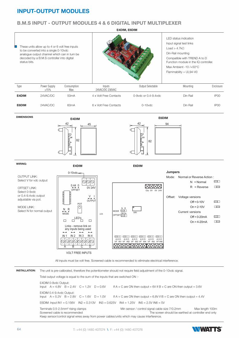
B.M.S InPUT - OUTPUT MODULES 4 & 6 DIGITAL InPUT MULTIPLEXErE4DIM, E6DIM
These units allow up to 4 or 6 volt free inputsto be converted into a single 0-10vdcanalogue output channel which can in turn bedecoded by a B.M.S controller into digitalstatus bits.
LED status indication
Input signal test links
Load > 4.7kΩ
Din-Rail mounting
Compatible with TREND A to D Function module in the IQ controller.
Max Ambient -10 /+50°C
Flammability = UL94-V0
Type Power Supply Consumption Inputs Output Selectable Mounting Enclosure ±15% Max. 24VAC/DC 230VAC
E4DIM 24VAC/DC 50mA 4 x Volt Free Contacts 0-9vdc or 0.4-9.4vdc Din Rail IP00
E6DIM 24VAC/DC 60mA 6 x Volt Free Contacts 0-10vdc Din Rail IP00
DIMENSIONS
WIRING:
INSTALLATION: The unit is pre-calibrated, therefore the potentiometer should not require field adjustment of the 0-10vdc signal.
Total output voltage is equal to the sum of the inputs that are switched ON :-
E4DIM 0-9vdc Output: Input A = 4.8V B = 2.4V C = 1.2V D = 0.6V If A + C are ON then output = 6V if B + C are ON then output = 3.6V
E4DIM 0.4-9.4vdc Output: Input A = 5.2V B = 2.8V C = 1.6V D = 1.0V If A + C are ON then output = 6.8V if B + C are ON then output = 4.4V
E6DIM: Input IN1 = 0.156V IN2 = 0.313V IN3 = 0.625V IN4 = 1.25V IN5 = 2.5V IN6 = 5V
Terminals 0.5-2.5mm² rising clamps Min sensor / control signal cable size 7/0.2mm Max length 100m Screened cable is recommended The screen should be earthed at controller end only Keep sensor/control signal wires away from power cables/units which may cause interference.
E4DIM E6DIM
42
82
9442
82
45
E4DIM
OUTPUT LINK:Select V for vdc output
OFFSET LINK:Select 0-9vdcor 0.4-9.4vdc outputadjustable via pot.
MODE LINK:Select N for normal output
E6DIM
Links - remove link on
any inputs being used
VOLT FREE INPUTS
0-10vdc
IN 1
A
LED's
IN 2 IN 3 IN 4
B C D
0V 24V
N R
0.44
OFFSET
MODE
OUTPUT
POT
0
V I
LED
A H O A H O A H O A H O A H O A H OVF IN1 VF IN2 VF IN3 VF IN4 VF IN5 VF IN6
MODE
OFFSETVR1
O/p 0V 0V 24V
Off On
N R
JumpersMode: Normal or Reverse Action :
N = Normal
R = Reverse
Offset: Voltage versions
Off = 0-10V
On = 2-10V
Current versions
Off = 0-20mA
On = 4-20mA
All inputs must be volt free. Screened cable is recommended to eliminate electrical interference.
[email protected] \ wattsindustries.co.uk
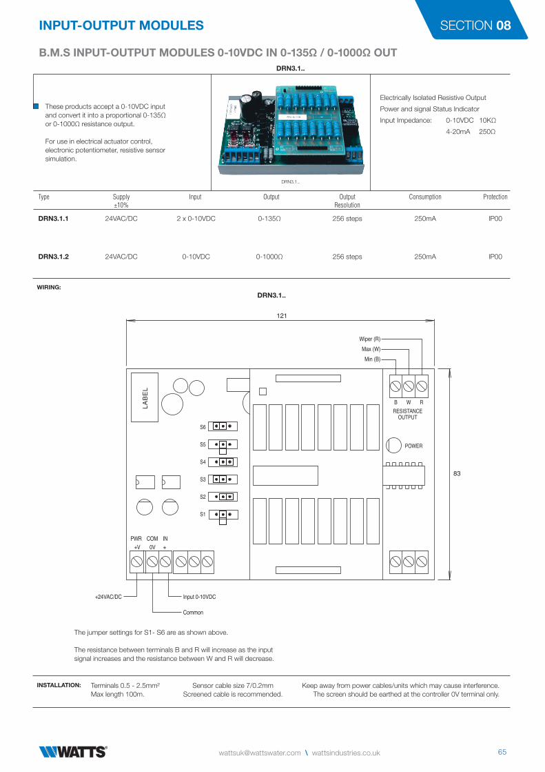
B.M.S INPUT-OUTPUT MODULES 0-10VDC IN 0-135Ω / 0-1000Ω OUT
InPUT-OUTPUT MODULES SECTION 08
DRN3.1..
These products accept a 0-10VDC inputand convert it into a proportional 0-135Ωor 0-1000Ω resistance output.
For use in electrical actuator control,electronic potentiometer, resistive sensorsimulation.
Electrically Isolated Resistive Output
Power and signal Status Indicator
Input Impedance: 0-10VDC 10KΩ
4-20mA 250Ω
Type Supply Input Output Output Consumption Protection ±10% Resolution
DRN3.1.1 24VAC/DC 2 x 0-10VDC 0-135Ω 256 steps 250mA IP00
DRN3.1.2 24VAC/DC 0-10VDC 0-1000Ω 256 steps 250mA IP00
WIRING:
INSTALLATION: Terminals 0.5 - 2.5mm² Sensor cable size 7/0.2mm Keep away from power cables/units which may cause interference.Max length 100m. Screened cable is recommended. The screen should be earthed at the controller 0V terminal only.
The jumper settings for S1- S6 are as shown above.
The resistance between terminals B and R will increase as the inputsignal increases and the resistance between W and R will decrease.
DRN3.1..
DRN3.1..
121
83
S6
S5
S4
S3
S2
S1
LAB
EL
+V 0V + PWR COM IN
+24VAC/DC Input 0-10VDC
Wiper (R)Max (W)Min (B)
RESISTANCEOUTPUT
POWER
B W R
Common
66 T: +44 (0) 1480 407074 \ F: +44 (0) 1480 407076
InPUT-OUTPUT MODULES
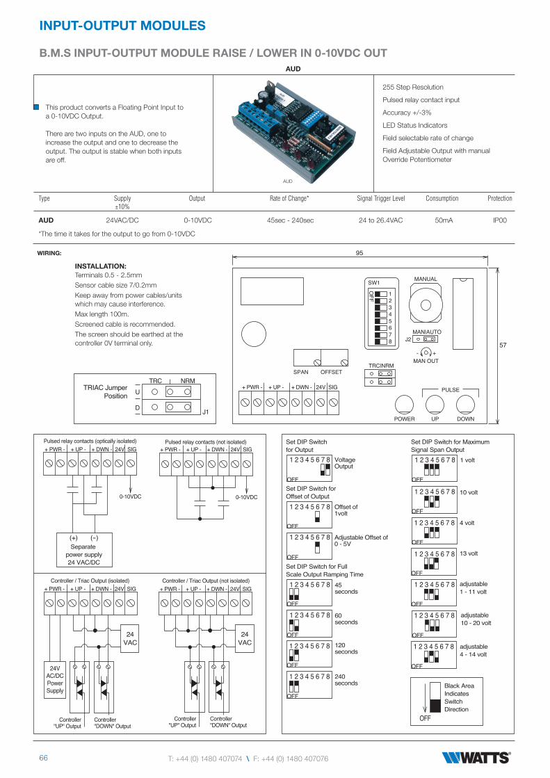
B.M.S InPUT-OUTPUT MODULE rAISE / LOWEr In 0-10VDC OUTAUD
This product converts a Floating Point Input toa 0-10VDC Output.
There are two inputs on the AUD, one toincrease the output and one to decrease theoutput. The output is stable when both inputsare off.
255 Step Resolution
Pulsed relay contact input
Accuracy +/-3%
LED Status Indicators
Field selectable rate of change
Field Adjustable Output with manual Override Potentiometer
Type Supply Output Rate of Change* Signal Trigger Level Consumption Protection ±10%
AUD 24VAC/DC 0-10VDC 45sec - 240sec 24 to 26.4VAC 50mA IP00
*The time it takes for the output to go from 0-10VDC
WIRING:
AUD
INSTALLATION: Terminals 0.5 - 2.5mmSensor cable size 7/0.2mmKeep away from power cables/units which may cause interference.Max length 100m.Screened cable is recommended.The screen should be earthed at the controller 0V terminal only.
95
57
1 2 3 4 5 6 7 8
1 2 3 4 5 6 7 8
1 2 3 4 5 6 7 8
1 2 3 4 5 6 7 8
1 2 3 4 5 6 7 8
1 2 3 4 5 6 7 8
1 2 3 4 5 6 7 8
1 2 3 4 5 6 7 8
1 2 3 4 5 6 7 8
1 2 3 4 5 6 7 8
1 2 3 4 5 6 7 8
1 2 3 4 5 6 7 8
1 2 3 4 5 6 7 8
1 2 3 4 5 6 7 8
OFF
OFF
OFF
OFF
OFF
OFF
OFF
OFF
OFF
OFF
OFF
OFF
OFF
OFF
Set DIP Switch for Maximum Signal Span Output
Set DIP Switch for Offset of Output
Set DIP Switchfor Output
Set DIP Switch for Full Scale Output Ramping Time
1 volt
10 volt
4 volt
13 volt
adjustable1 - 11 volt
adjustable10 - 20 volt
adjustable4 - 14 volt
45seconds
60seconds
120seconds
240seconds
VoltageOutput
Offset of1volt
Adjustable Offset of0 - 5VSeparate
power supply24 VAC/DC
(+) (-)
24VAC
24VAC
24VAC/DCPowerSupply
Controller"UP" Output
Controller"DOWN" Output
Controller"UP" Output
Controller"DOWN" Output
+ PWR - + UP - + DWN - 24V SIG
+ PWR - + DWN - 24V SIG+ UP -
+ PWR - + UP - + DWN - 24V SIG
+ PWR - + UP - + DWN - 24V SIG
0-10VDC
+ PWR - + UP - + DWN - 24V SIG
Controller / Triac Output (not isolated)Controller / Triac Output (isolated)
Pulsed relay contacts (optically isolated) Pulsed relay contacts (not isolated)
OFF
Black AreaIndicatesSwitchDirection
TRIAC JumperPosition
J1
TRC NRMU
D
SPAN OFFSET
SW1
OFF
MANUAL
MAN|AUTO
TRC|NRM
J2
12345678
MAN OUT
POWER UP DOWN
PULSE
- +
0-10VDC
[email protected] \ wattsindustries.co.uk
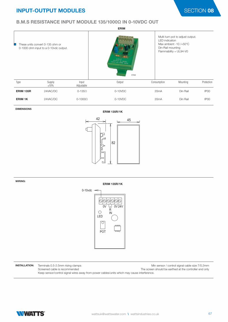
B.M.S RESISTANCE INPUT MODULE 135/1000Ω IN 0-10VDC OUT
InPUT-OUTPUT MODULES SECTION 08
ERIM
These units convert 0-135 ohm or0-1000 ohm input to a 0-10vdc output.
Multi-turn pot to adjust output.LED indicationMax ambient -10 /+50°CDin-Rail mountingFlammability = UL94-V0
Type Supply Input Output Consumption Mounting Protection ±10% Adjustable
ERIM 135R 24VAC/DC 0-135Ω 0-10VDC 20mA Din Rail IP00
ERIM 1K 24VAC/DC 0-1000Ω 0-10VDC 20mA Din Rail IP00
DIMENSIONS
WIRING:
INSTALLATION: Terminals 0.5-2.5mm rising clamps Min sensor / control signal cable size 7/0.2mmScreened cable is recommended The screen should be earthed at the controller end onlyKeep sensor/control signal wires away from power cables/units which may cause interference.
ERIM
ERIM 135R/1K
4542
82
ERIM 135R/1K
LED
POT
0V 24V0V
R
IN
0-10vdc

68 T: +44 (0) 1480 407074 \ F: +44 (0) 1480 407076
InPUT-OUTPUT MODULES
TrAnSMITTEr SETPOInT COnTrOLLEr 0-10VDC / 4-20MA In 0-10VDC OUTE10-10
This product can be used with pressure,temperature, humidity, flow or leveltransmitters. By connecting the transmitteroutput into this controller a setpoint can beadjusted and a 0-10VDC output will be producedover the desired proportional band.
Input current > 0.5mA
Max Ambient -10/+50°C
Flammability = UL94-V0
Type Setpoint Proportional Input Output Supply Consumption Mounting Enclosure Range Band ±15%
E10-10 0-100% 0-50% 0-10VDC or 4-20mA 0-10VDC 24VAC/DC 32mA Din Rail IP00
DIMENSIONS
WIRING:
INSTALLATION: Terminals 0.5-2.5mm² rising clamps Min sensor / control signal cable size 7/0.2mmScreened cable is recommended The screen should be earthed at the controller end onlyKeep sensor/control signal wires away from power cables/units which may cause interference.
E10-10
E10-10
E10-10
45
82
66
EXAMPLES: E10-10 used with a pressure transmitter ie range 0-16 bar & 0-10vdc output.A setpoint of 50% represents 8 bar. A prop band of 10% represents 1.6 bar (10% of the range) J4 & J5 link on 0-10.Therefore the output will be 0-10vdc linear over the range from 8 bar 0vdc to 9.6 bar 10vdc.If J4 & J5 link is on 10-0 then the output will be 0-10vdc linear over the range from 8 bar 0vdc to 6.4 bar 10vdc.
E10-10 used with a humidity transmitter ie range 0-100% RH & 0-10vdc output.A setpoint of 40% represents 40% RH. A prop band of 20% represents 20% RH (20% of the range) J4 & J5 link on 0-10.Therefore the output will be 0-10vdc linear over the range from 40% RH 0vdc to 60% RH 10vdc.If J4 & J5 link is on 10-0 then the output will be 0-10vdc linear over the range from 40% RH 0vdc to 20% RH 10vdc.
I-V Conv0-10 Out0-10 Out
offsetno offset
Out 10-0Out 10-0In 4-20mAIn 4-20mA
100
normal
internalJ2
50
Setpoint
0%
J6J7
J3J4J5
OV 24V+
J1
INPUT
Prop Band
25
%0 50
0-10V In0-10V In
Offset
OV 10VDC
OUTPUT
4-20mA+
0V 10VDC
INPUT
remote
J1 Fit link to internal
J2 To select remote setpoint offset ±5% or no offset
J3 Select I-V Conv to convert a 4-20mA input signal directly to 0-10VDC Output. The setpoint adj has no effect in this mode.
J4 & J5 Set both to 0-10 with rising input above the setpoint, the output also rises. Set both to 10-0 with falling input below the setpoint, the output rises.
J6 & J7 Set both to 4-20mA or 0-10V to select the input signal

[email protected] \ wattsindustries.co.uk
B.M.S InPUT - OUTPUT MODULES AnALOGUE rESCALInG VDC / MA
InPUT-OUTPUT MODULES SECTION 08
31
6060
94
ARM
This unit can be used to convert / rescale current or voltage signals:
VDC input converted to mA output. mA input converted to VDC output. mA or VDC input to mA or VDC reversed output. Enlarging or reducing signals.
Adjustments are made using the potentiometers.
Input Impedence:
1MΩ Voltage 250Ω Current
Consumption: 200mA maximum
Output current: 44mA maximum
LED Power Indicator
Common Applications :
4-20mA in to 0-10vdc out
0-10vdc in to 4-20mA out
Reversed Output
Signal / Sensor Range adjustment
Type Supply Input Output Ambient Ambient Mounting Protection ± 10% Adjustable Adjustable Humidity Temp °C
ARM 24VAC/DC 0 - 44 mA 1 - 44 mA 10 to 95% 0-50 Panel IP00 0 -35 vdc 0.25 - 20 vdc non-condensing
DIMENSIONS
ARM
ARM
SETUP : Factory Calibration -
No Attenuation of the Input SignalVoltage InputVoltage OutputNormal Acting Output SignalNo Offset to the Output SignalGain of 1 to the Output Signal (1:1)
Trim Pots Fully ClockwiseFINEGAIN = gain of 1REV = 0 volts reverseOFFSET = 0 volts offset
Trim Pots Fully Counter-clockwiseATTN = no input signal attenuation
The input signal is NOT isolated from the output.When using a 24VAC supply, all devices connectedto the ARM must use the same ground.Terminals 0.5-2.5mm .Min cable size 7/0.2mm. Max length 100mKeep sensor/control signal wires away frompower cables/units which may cause interference.Screened cable is recommended
0-10vdc to 5-10VDCJ1 to normal position.J2 to positive position.J3 to voltage input, voltage output.Apply 0vdc to the input.Adjust OFFSET for a 5vdc output.Apply 10vdc to the input.Adjust ATTN for a 10vdc output.
0-10VDC to 4-20mAJ1 to normal position.J2 to positive position.J3 to voltage input, current output.Apply 0vdc to the input.Adjust OFFSET for a 4mA output.Apply 10vdc to the input.Adjust ATTN for a 20mA output.
4-20mA to 0-10VDCJ1 to normal position.J2 to negative position.J3 to current input, voltage output.Apply 4mA to the input.Adjust OFFSET for a 0vdc output.Apply 20mA to the input.Adjust GAIN for a 10vdc output.
0-10VDC to 8-2VDCJ1 to reverse position.J2 to no offset position.J3 to voltage input, voltage output.Apply 0vdc to the input.Adjust REV for an 8vdc output .Apply 10vdc to the input.Adjust ATTN for a 2vdc output.
0-10VDC to 0-5VDCJ1 to normal position.J2 to no offset position.J3 to voltage input, voltage output.Apply 0vdc to the input.Check output is 0vdc.Apply 10vdc to the input.Adjust ATTN for a 5vdc output.
Jumper Settings -
J1 - Output Direction
Reverse
Normal
J2 - Offset Setting
No Offset
Negative
Positive
J3 - Input / Output Setting
Current OutputCurrent Input
Voltage OutputCurrent Input
Current OutputVoltage Input
Voltage OutputVoltage Input
NOTE : Equivalent Calibration voltage = Required Input Signal Amps x 250 (ie. 4mA is 0.004 x 250 =1vdc and 20mA is 0.020 x 250 =5vdc) Set up the unit with a voltage input and / or output (changing J3) using the formula. If required change J3 back to the correct setting.

70 T: +44 (0) 1480 407074 \ F: +44 (0) 1480 407076
InPUT-OUTPUT MODULES
B.M.S InPUT - OUTPUT MODULES AnALOGUE BUFFEr MODULE 0-10VDCABM4
This unit can be used to generate / reroute up to four 0-10vdc signals:
Applications include - Manual adjustment of the0-10vdc signal potentiometer can be used toposition actuators etc, providing commissioningtest signals, buffering one signal to drive severalactuators or buffering four signals to drive fouractuators - each of which draws a high inputsignal current.
Direct / Buffer / Off Link Selectable
Hand / Auto Link Selectable
LED Power Indicator
Output Signal Current: 20mA per channel
Output Power Current: 6A
Operating Current: 260mA AC 115mA DC
Input Time Constant: 1ms
Manual Output Adjustment
Output Voltage Test Points
Terminals: Rising Clamps 0.5-2.5mm²
Type Supply Input Output Ambient Ambient Mounting Protection ± 10% Direct or Buffered Humidity Temp °C
ABM4 24VAC/DC 0 - 10 vdc 0 - 10 vdc 0 to 90% 0-50 Din Rail IP00 non-condensing
DIMENSIONS
ABM4
56
82
100
OP 0V 24V OP 0V 24V OP 0V 24V OP 0V 24 V
HAND
FROM IP1
HAND HAND HAND
FROM IP2 FROM IP3 FROM IP4
FROM IP1 FROM IP1 FROM IP1
FROM IP4
DIR OFF
BUFF
DIR OFF
BUFF
DIR OFF
BUFF
DIR OFF
BUFF
0 10
5
0 10
5
0 10
5
0 10
5
IP1 IP2 IP3 IP4 24V 0V
FUSE
LED
POT ADJ.
INSTALLATION:
Selecting Inputs -
Each output separate Output 1 linked to input 1 Output 2 linked to input 2 Output 3 linked to input 3 Output 4 linked to input 4
Two linked, two separate Output 1 linked to input 1 Output 2 linked to input 1 Output 3 linked to input 3 Output 4 linked to input 4
Two sets of two linked Output 1 linked to input 1 Output 2 linked to input 1 Output 3 linked to input 4 Output 4 linked to input 4
Three linked, one separate Output 1 linked to input 1 Output 2 linked to input 1 Output 3 linked to input 1 Output 4 linked to input 4
All linked Output 1 linked to input 1 Output 2 linked to input 1 Output 3 linked to input 1 Output 4 linked to input 1
HAND
FROM IP1
HAND HAND HAND
FROM IP2 FROM IP3 FROM IP4
FROM IP1 FROM IP1 FROM IP1
FROM IP4
HAND
FROM IP1
HAND HAND HAND
FROM IP2 FROM IP3 FROM IP4
FROM IP1 FROM IP1 FROM IP1
FROM IP4
HAND
FROM IP1
HAND HAND HAND
FROM IP2 FROM IP3 FROM IP4
FROM IP1 FROM IP1 FROM IP1
FROM IP4
HAND
FROM IP1
HAND HAND HAND
FROM IP2 FROM IP3 FROM IP4
FROM IP1 FROM IP1 FROM IP1
FROM IP4
HAND
FROM IP1
HAND HAND HAND
FROM IP2 FROM IP3 FROM IP4
FROM IP1 FROM IP1 FROM IP1
FROM IP4
Buffering Outputs -
When an output is set to BUFFERthe signal is buffered to 20mAin both HAND and AUTO modes.
When an output is set to DIRECT,the signal is only powered from thepot in HAND mode or the input inAUTO mode.
When the output is set to OFF,the output signal is open circuit.
Hand Mode -
When an input link is set to HAND,the output signal can be set byadjusting the associated pot.
NOTE -
All the 0v terminals are common.There must be only one link usedper channel.
DIR OFF
BUFF
DIR OFF
BUFF
DIR OFF
BUFF
Min sensor / control signal cable size 7/0.2mm Max length 100m. Screened cable is recommended.The screen must be earthed at controller end only Keep sensor/control signal wires away from power cables/units which may cause interference.
EXAMPLES : HAND
FROM IP1
HAND HAND HAND
FROM IP2 FROM IP3 FROM IP4
FROM IP1 FROM IP1 FROM IP1
FROM IP4
DIR OFF
BUFF
DIR OFF
BUFF
DIR OFF
BUFF
DIR OFF
BUFF
HAND
FROM IP1
HAND HAND HAND
FROM IP2 FROM IP3 FROM IP4
FROM IP1 FROM IP1 FROM IP1
FROM IP4
DIR OFF
BUFF
DIR OFF
BUFF
DIR OFF
BUFF
DIR OFF
BUFF
HAND
FROM IP1
HAND HAND HAND
FROM IP2 FROM IP3 FROM IP4
FROM IP1 FROM IP1 FROM IP1
FROM IP4
DIR OFF
BUFF
DIR OFF
BUFF
DIR OFF
BUFF
DIR OFF
BUFF
Each output buffered and adjusted by pot. All outputs buffered and follow input 1. Outputs 1 & 2 buffered and follow input 1. Output 3 not buffered and follows input 3. Output 4 buffered and follows pot.
[email protected] \ wattsindustries.co.uk
TrAnSFOrMErS
InPUT-OUTPUT MODULES SECTION 08
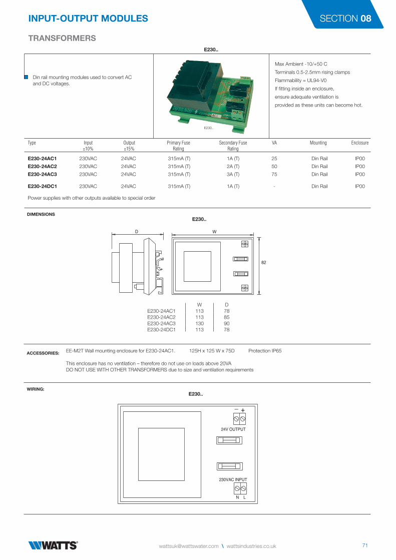
E230..
Din rail mounting modules used to convert ACand DC voltages.
Max Ambient -10/+50 C
Terminals 0.5-2.5mm rising clamps
Flammability = UL94-V0
If fitting inside an enclosure,
ensure adequate ventilation is
provided as these units can become hot.
Type Input Output Primary Fuse Secondary Fuse VA Mounting Enclosure ±10% ±15% Rating Rating
E230-24AC1 230VAC 24VAC 315mA (T) 1A (T) 25 Din Rail IP00
E230-24AC2 230VAC 24VAC 315mA (T) 2A (T) 50 Din Rail IP00
E230-24AC3 230VAC 24VAC 315mA (T) 3A (T) 75 Din Rail IP00 E230-24DC1 230VAC 24VAC 315mA (T) 1A (T) - Din Rail IP00
Power supplies with other outputs available to special order
ACCESSORIES: EE-M2T Wall mounting enclosure for E230-24AC1. 125H x 125 W x 75D Protection IP65
This enclosure has no ventilation – therefore do not use on loads above 20VADO NOT USE WITH OTHER TRANSFORMERS due to size and ventilation requirements
E230..
DIMENSIONSE230..
W DE230-24AC1 113 78E230-24AC2 113 85E230-24AC3 130 90E230-24DC1 113 78
WIRING:E230..
W DE230-24AC1 113 78E230-24AC2 113 85E230-24AC3 130 90E230-24DC1 113 78
D W
82
N L
230VAC INPUT
24V OUTPUT
_ +

© 2017 WattsELECTRO CATALOGUE-UK-W-UK UK-W-UK-05-2017-Rev0
Watts Industries UK LtdColmworth Business Park, Eaton Socon, St. Neots, PE19 8YX, UK
T: +44 (0) 1480 407074 • F: +44 (0) 1480 [email protected] • wattsindustries.co.uk


