CAUTION: Metra recommends disconnecting the negative battery terminal before beginning any installation. All accessories, switches, and especially air bag indicator lights must be plugged in before reconnecting the battery or cycling the ignition.
NOTE: Refer to the instructions included with the aftermarket radio.
• ISO DIN radio provision with pocket• DDIN radio provision• Integrated location for driver info display screen • Painted to match factory color and finish
• A) Radio housing trim panel • B) Brackets • C) Trim panel bracket • D) Pocket • E) ISO DIN pocket • F) LCD housing • G) LCD back plate • H) (6) #8 x 3/8” Phillips truss-head screws • I) (4) #8 x 3/8” Phillips pan-head screws • J) (3) Panel clips
– ISO DIN radio provision with pocket ..................... 5
– DDIN radio provision ............................................ 6
Table of Contents
GFIH J
99-3015G
2
Dash Disassembly
1. Unsnap panel above radio screen. (Figure A)
2. Unsnap and remove the trim panel on the outer driver’s edge of dash. (Figure B)
3. Remove (1) screw from left side of panel below steering column (panel does not need fully removed) (Figure C)
4. Unsnap and remove center console cover. (Figure D)
5. Unsnap and remove panel above glove box. (Figure E)
Continued on next page
(Figure D)(Figure B)
(Figure A)
(Figure E)(Figure C)
99-3015G
3
Dash Disassembly
6. Remove (1) 7 mm screw and remove the small trim next to left-center vent (also push-to-start in some models). (Figure F)
7. Remove (2) 7 mm screws from the radio/climate control panel then unclip and remove the panel. (Figure G)
8. Remove (3) 7 mm per vent and remove the vents. (Figure H)
9. Remove (4) screws and remove radio. (Figure I)
10. Remove (2) 7 mm and remove CD player. (Figure J)
Continue to kit assembly
(Figure F) (Figure I)
(Figure G) (Figure J)
(Figure H)
99-3015G
4
Kit Assembly
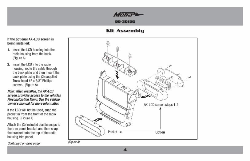
If the optional AX-LCD screen is being installed:
1. Insert the LCD housing into the radio housing from the back. (Figure A)
2. Insert the LCD into the radio housing, route the cable through the back plate and then mount the back plate using the (2) supplied Truss-head #8 x 3/8” Phillips screws. (Figure A)
Note: When installed, the AX-LCD screen provides access to the vehicles Personalization Menu. See the vehicle owner’s manual for more information
If the LCD will not be used, snap the pocket in from the front of the radio housing. (Figure A)
Attach the (3) included plastic snaps to the trim panel bracket and then snap the bracket onto the top of the radio housing trim panel.
Continued on next page (Figure A)
AX-LCD screen steps 1-2
Pocket Option
99-3015G
5
Kit Assembly
ISO DIN radio provision
1. Connect the radio brackets to the radio housing trim panel with the (4) #8 x 3/8” Truss-head Phillips screws supplied. (Figure A)
2. Mount the pocket to the bracket/panel assembly with the (4) #8 x 3/8” Pan-head Phillips screws supplied. (Figure B)
3. Slide the radio into the assembly and secure with screws supplied with the radio. (Figure C)
4. Locate the factory wiring harness and antenna plug in the dash. Metra recommends using the proper mating adapters from Metra and/or AXXESS. Test everything.
5. Mount the new radio assembly into the dash and reassemble dash in reverse order of disassembly.
(Figure A) (Figure C)(Figure B)
99-3015G
6
(Figure A) (Figure B)
Kit Assembly
DDIN radio provision
1. Connect the radio brackets to the radio housing trim panel with the (4) #8 x 3/8” Truss-head Phillips screws supplied. (Figure A)
2. Slide the radio into the assembly and secure with screws supplied with the radio. (Figure B)
3. Locate the factory wiring harness and antenna plug in the dash. Metra recommends using the proper mating adapters from Metra and/or AXXESS. Test everything.
4. Mount the new radio assembly into the dash and reassemble dash in reverse order of disassembly.
99-3015G
Notes
7
REV.
11/
14/2
017
INS
T99-
3015
G
KNOWLEDGE IS POWEREnhance your installation and fabrication skills by enrolling in the most recognized and respected mobile electronics school in our industry.Log onto www.installerinstitute.com or call 800-354-6782 for more information and take steps toward a better tomorrow.
INSTRUCCIONES DE INSTALACIÓN PARA LA PIEZA 99-3015G
REV.
11/
14/2
017
INS
T99-
3015
G
PRECAUCIÓN: Metra recomienda desconectar el terminal negativo de la batería antes de comenzar cualquier instalación. Todos los accesorios, interruptores y, especialmente, las luces indicadoras de airbag deben estar enchufados antes de volver a conectar la batería o comenzar el ciclo de ignición.
Nota: Remítase a las instrucciones incluidas con el radio de posventa.
• Herramienta para quitar paneles • Destornillador Phillips
HERRAMIENTAS REQUERIDAS
• Provisión de radio ISO DIN con cavidad• Provisiones de radio DDIN• Ubicación integrada de la pantalla de información para el conductor • Pintado para igualar el color y acabado de fábrica
• A) Panel de moldura de la carcasa del radio • B) Soportes • C) Soporte del panel de moldura • D) Cavidad • E) Cavidad ISO DIN • F) Carcasa del LCD • G) Placa posterior del LCD • H) (6) tornillos Phillips #8 x 3/8” de cabeza segmentada • I) (4) tornillos Phillips #8 x 3/8” de cabeza troncocónica • J) (3) ganchos para panel
CARACTERÍSTICAS DEL KIT
COMPONENTES DEL KIT
CABLEADO Y CONEXIONES DE ANTENA (se venden por separado)Arnés de cableado: • Arnés GMOS-LAN-09 o interfase HYBL-01Adaptador de antena: • 40-EU55 Accesorios opcionales: • AX-LCD - Pantalla de información
Chevrolet Tahoe/Suburban, GMC Yukon/Yukon Denali 2015 y mas
99-3015G Desmontaje del tablero
– Chevrolet Tahoe/Suburban, ... GMC Yukon/Yukon Denali 2015 y mas ...............2-3
Ensamble del kit
– Instalación de AX-LCD opcional ........................... 4
– Provisión de radio ISO DIN con cavidad ................. 5
– Provisiones de radio DDIN .................................... 6
A B EC D
GF IH J
99-3015G
Desmontaje del tablero
2
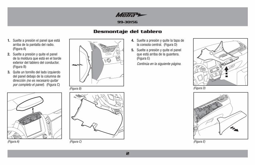
1. Suelte a presión el panel que está arriba de la pantalla del radio. (Figura A)
2. Suelte a presión y quite el panel de la moldura que está en el borde exterior del tablero del conductor. (Figura B)
3. Quite un tornillo del lado izquierdo del panel debajo de la columna de dirección (no es necesario quitar por completo el panel). (Figura C)
4. Suelte a presión y quite la tapa de la consola central. (Figura D)
5. Suelte a presión y quite el panel que está arriba de la guantera. (Figura E)
Continúa en la siguiente página.
(Figura D)(Figura B)
(Figura E)(Figura C)(Figura A)
99-3015G
3
Desmontaje del tablero
6. Quite (1) moldura pequeña de 7 mm que está junto a la rejilla central izquierda (también de presión para iniciar en algunos modelos). (Figura F)
7. Quite (2) 7 mm tornillos del panel de control de radio/clima luego soltar y retirar el pael. (Figura G)
8. Quite (3) de 7 mm por rejilla y quite las rejillas. (Figura H)
9. Quite los (4) tornillos y quite el radio. (Figurea I)
10. Quite (2) de 7 mm y quite el reproductor de CD. (Figura J)
Continúe con el ensamble del kit
(Figurae F) (Figura I)
(Figura G) (Figura J)
(Figura H)
99-3015G
Ensamble del kit
Si se va a instalar la pantalla opcional AX-LCD:
1. Inserte la carcasa del LCD en la carcasa del radio desde atrás. (Figura A)
2. Inserte el LCD en la carcasa del radio, enrute el cable a través de la placa posterior y luego monte la placa posterior usando los (2) tornillos Phillips #8 x 3/8” de cabeza segmentada. (Figura A)
Nota: Cuando se instala, la pantalla AX-LCD ofrece acceso al menú de personalización del vehículo. Consulte el manual del propietario del vehículo para más información.
Si el LCD no se usará, enganche la cavidad desde el lado delantero de la carcasa del radio. (Figura A)
Sujete los (3) ganchos de plástico incluidos en el soporte del panel de la moldura y luego enganche el soporte en la parte superior del panel de la moldura de la carcasa del radio.
Continúa en la siguiente página.(Figura A)
Pasos 1-2 de la pantalla AX-LCD
Cavidad Opción
4
99-3015G
Ensamble del kit
Provisión de radio ISO DIN
1. Coloque los soportes del radio en el panel de la moldura de la carcasa del radio con los (4) tornillos Phillips #8 x 3/8” suministrados. (Figura A)
2. Monte la cavidad en el ensamble de soporte/panel con los (4) tornillos Phillips #8 de 3/8” suministrados. (Figura B)
3. Deslice el radio en el ensamble y sujételo con los tornillos suministrados con el radio. (Figura C)
4. Localice el arnés de cables de fábrica y el conector de la antena en el tablero. Metra recomienda que use adaptadores adecuados de acoplamiento de Metra y/o de AXXESS. Realice una prueba a todo el sistema.
5. Monte el conjunto del radio en el tablero y vuelva a armar el tablero al revés de como lo desarmó.
5
(Figura A) (Figura C)(Figura B)
99-3015G
(Figura A) (Figura B)
Ensamble del kit
Provisión de radio DDIN
1. Coloque los soportes del radio en el panel de la moldura de la carcasa del radio con los (4) tornillos Phillips #8 x 3/8” suministrados. (Figura A)
2. Deslice el radio en el ensamble y sujételo con los tornillos suministrados con el radio. (Figura B)
3. Localice el arnés de cables de fábrica y el conector de la antena en el tablero. Metra recomienda que use adaptadores adecuados de acoplamiento de Metra y/o de AXXESS. Realice una prueba a todo el sistema.
4. Monte el conjunto del radio en el tablero y vuelva a armar el tablero al revés de como lo desarmó.
6
99-3015G
Notas
7
INSTRUCCIONES DE INSTALACIÓN PARA LA PIEZA 99-3015G
REV.
11/
14/2
017
INS
T99-
3015
G
KNOWLEDGE IS POWEREnhance your installation and fabrication skills by enrolling in the most recognized and respected mobile electronics school in our industry.Log onto www.installerinstitute.com or call 800-354-6782 for more information and take steps toward a better tomorrow.
Metra recomienda técnicos con certificación del Programa de Certificación en Electrónica Móvil (Mobile Electronics Certification Program, MECP).
EL CONOCIMIENTO ES PODERMejore sus habilidades de instalación y fabricación inscribiéndose en la escuela de dispositivos electrónicos móviles más reconocida y respetada de nuestra industria. Regístrese en www.installerinstitute.com o llame al 800-354-6782 para obtener más información y avance hacia un futuro mejor.