27
Building Safety THE PROFESSIONAL JOURNAL OF CONSTRUCTION AND FIRE SAFETY JOURNAL INSIDE: “MAKING FIRE ALARM SYSTEMS ADA COMPLIANT,” GOING GREEN MAY 2003
MAY 2003
$5.0
0Building SafetyT H E P R O F E S S I O N A L J O U R N A L O F C O N S T R U C T I O N A N D F I R E S A F E T Y
JOURNAL
INSIDE: “MAKING FIRE ALARM SYSTEMS ADA COMPLIANT,” GOING GREEN
MAY 2003
Building Safety Departments
4 A Message from the CEO by Bob D. Heinrich
7 Meet the ICC Board of Directors
Alternate MaterialsDesigns & Methods
14 Going Green by David Eisenberg
16 Optimizing Wood Framingby Peter Yost and Ann Edminster
20 2003 I-Codes Adopt Revolutionary Frost-Protection Technology by Dick Morris
24 The Case for Conditioned, Unvented Crawl Spaces by Dr. Nathan Yost, M.D.
28 Green Roofs: A New American Building System by Charles D. Miller, P.E.
32 Rubble Trench Foundations—A Brief Overview by Sigi Koko
35 Integrating Green Building Practices Into the Building Regulatory Processby Anthony Floyd, AIA, C.B.O., and Edward Peaser, C.B.O.
40 Get Involved in the Codes!by Jim W. Sealy, FAIA, NCARB
42 An Invitation to Attend Codes Forum 2003
Features
JOURNALTM
The views and conclusions expressed in articles herein are solely those of the authors, not necessarily those of the staff, Board of Directors or members ofthe International Code Council ®. Advertising copy is carefully reviewed, but publication herein does not imply endorsement of any product or service offered.Building Safety Journal TM reserves the right to reject any advertisement in accordance with the established advertising guidelines of the International CodeCouncil. Photographs and artwork submitted to Building Safety Journal become the property of the International Code Council and cannot be returned.
3 Message from the President
13 Letter to the Editor
45 IAS Accreditation Criteria
Inside the ICC46 News
48 Chapter Channel
50 Public Policy
51 15 Minutes with the ICC Staff
53 Seminar Spotlight
53 From the Trenches
54 ICC Seminars
56 Voluntary Certification
58 Fire ServicesMaking Fire Alarm SystemsADA Compliant
62 Industry Headlines
68 Calendar
70 Building Valuation Data
81 Professional Directory
May 2003 Building Safety Journal 1
The Professional Journal of Construction and Fire Safety VOLUME I • NUMBER 3 • MAY 2003
14
16
20
28
35
Cover design by Mary Bridges
14 Building Safety Journal May 2003
It is a great pleasure to introduce the firstfeature issue of Building Safety Journal™
with a focus on green building and alternatematerials, methods and designs. Althoughthis is a first for Building Safety Journal, itrepresents the continuation of work theDevelopment Center for AppropriateTechnology (DCAT) has been doing withcode organizations over many years.
Those of you familiar with ICBO’s for-mer magazine, Building Standards™, mayrecall the three feature issues with a similar focus that were published starting in the fall of 1998 (September–October 1998,January–February 2000 and March–April2002). These features were the result of acollaboration between DCAT, ICBO and the many authors who contributed their expertise. As with thosepast features, DCAT was asked to help pull together this current set of articles with the aim of providing use-ful and accurate information to the codes community, the design and building sectors, and the public.
For those who might not have seen the earlier features, they’re still available at “Building StandardsOnline” on the ICBO website. For an overview of DCAT’s work and goals, I highly recommend theJanuary–February 2000 Building Standards interview with Bob Fowler and me, “An Alternative Future forBuilding Regulation.” It will give you a pretty good idea of what DCAT is doing and why, and what Fowler,the Founding Chairman of ICC (among a multitude of other extraordinary accomplishments), thought aboutthis effort. A great mentor to me as well as thousands of others, Bob had many insightful things to say inthat interview—perhaps none more important than the following.
We need to think about the responsibilities for our collective safety; especially thewelfare of future generations who, it’s worth noting, are unable to represent their interests.
If there is a theme that connects the feature articles in this issue of Building SafetyJournal, it is that they all represent alternate approaches to building which may help usmove in the direction of more sustainable construction. That is, they are about approachesthat aim to meet current needs while taking into account the welfare of future generations.
When considering the efforts of people who are working to make buildings more environmentally responsible, it is important to note that they’re as committed to buildingsafety as everyone else. None of us want unsafe buildings. However, we are also awareof the reality that much of the risk that we think we are eliminating is actually just beingmoved in space and time. Many of the requirements applied to our modern buildings toensure that they rarely burn or fall down; allow people to become trapped within or fallfrom them; or expose occupants to the risks of electrocution, freezing or suffocation
create real and significant risks away from the building site—out in the natural systems thatsupport all life on the planet. Similarly, our actions shift that risk from the present to the future—to ourchildren and grandchildren and to the future generations of all the other species on whose welfare our well-being also depends. This is the responsibility that Bob spoke of and cared about so passionately.
That we don’t yet know how to figure out what the appropriate safety factors are for these other types ofrisks—that we don’t even know what all the risks are, much less how to quantify them—does not relieve
Change is typicallyaccompanied by a sense ofheightened risk, but it is criti-cal to bear in mind that onlywhen we can see the risksinherent in current practicecan we appropriately balancewhat may appear to be thegreater risks of change.
Going Greenby David Eisenberg
Director, Development Center for Appropriate Technology
GREEN BUILDING ANDALTERNATEMATERIALS,METHODS AND DESIGNS
EFFICIENT WOOD FRAMING TECHNIQUES
FROST-PROTECTED SHALLOW FOUNDATIONS
ALTERNATIVEAPPROACHES TOVENTILATIONFOR CRAWLSPACES
GREEN ROOFS
RUBBLE TRENCH FOUNDATIONS
USEFULINFORMATION TO THE CODES COMMUNITY
us of our responsibility to address them. It requires us to bemore careful in our assumptions and decisions—to balance theunknown with the known and to be willing to consider how webegin designing and building for the long haul, rather than theshort-term.
The alternate approaches in this feature are steps in that direc-tion, and like so many other such steps, they involve change.Change is typically accompanied by a sense of heightened risk,but it is critical to bear in mind that only when we can see therisks inherent in current practice can we appropriately balancewhat may appear to be the greater risks of change.
At DCAT, we believe that humankind is at a crucial point inhistory when we have both the urgent need and the phenome-nal opportunity to learn to make our human systems compati-ble with and beneficial for the natural and living systems onEarth. Code officials are in a strategic position to either facil-itate or impede this change. I and other alternate constructionadvocates see our work, in part, as providing good informationin a broad enough context to help inspire code officials tomake reasoned, well-informed decisions.
The articles in this current feature cover a range of topics,some already addressed in the I-CodesTM (such as efficientwood framing techniques and frost-protected shallow founda-tions), others less widely known (like alternate approaches toventilation for crawl spaces, green roofs and rubble trenchfoundations). I hope that they prove both interesting and beneficial. You will be seeing articles on related topics infuture issues of Building Safety Journal, and beginning withthe June issue I will be writing a regular column similar to the“Building Codes for a Small Planet” column that appeared inBuilding Standards last year. ◆
David Eisenberg co-authored The Straw Bale House andhelped write the first load-bearing straw bale constructionbuilding code for Tucson and Pima County, Arizona. He canbe contacted by phoning the Development Center forAppropriate Technology (DCAT) at (520) 624-6628 or via e-mail at [email protected]. For more information aboutDCAT, direct your browser to www.dcat.net.
May 2003 Building Safety Journal 15
Online Green Building ResourcesThe Development Center for Appropriate Technology
(DCAT) – www.dcat.netEcological Building Network – www.ecobuildnetwork.orgBuilding Science Corporation – www.buildingscience.comEnergy and Environmental Building Association –
www.eeba.orgU.S. Green Building Council – www.usgbc.orgBuilding America (U.S. Department of Energy) –
www.eere.energy.gov/buildings/building_americaNew Buildings Institute – www.newbuildings.org
The following green building articles and features can befound on DCAT’s website at: www.dcat.net/resources/reviews.php#articles.
September–October 1998“Building a Sustainable Future”“Straw-Bale Construction”“Straw-Bale Construction: A Building Official’s Perspective”“Rammed Earth: Developing New Guidelines for an
Old Material”“Rammed Earth: A Code Official’s Perspective”
“Pozzolans Unpuzzled: As Mineral Admixtures, Fly Ashand Other Waste Products Add Strength and Durability to Concrete”
The “Earth Architecture and Ceramics: The Sandbag/ Superadobe/Superblock Construction System”“Sandbag/Superadobe/Superblock: A Code Official Perspective”“Adobe: A Present from the Past”“Adobe: A Code Official’s Perspective”
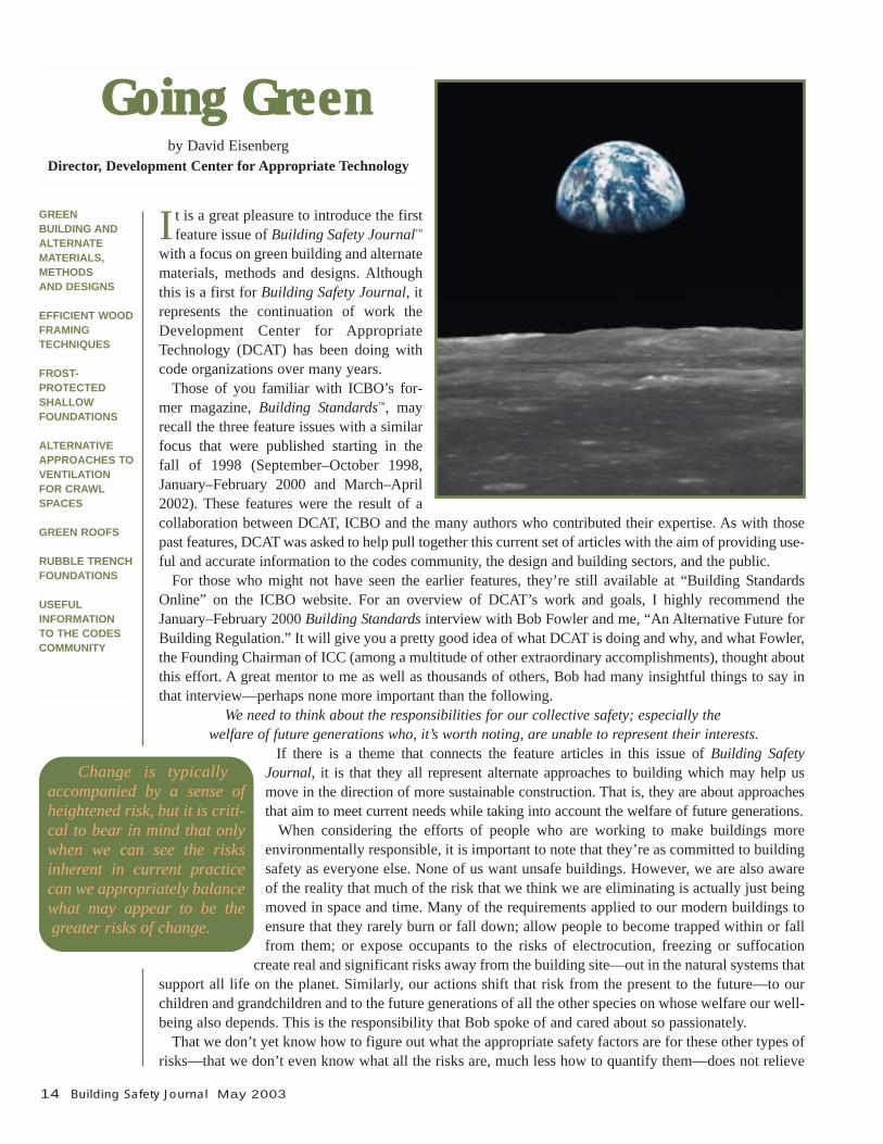
January–February 2000“An Alternative Future for Building Regulation”“Lunar and Terrestrial Sustainable Building Technology
in the New Millennium”“Cast Earth: A Revolutionary Building Concept”“Cob and the Building Code”“Cob Construction”“Building With Bamboo”“Earthship Building: An Ecocentric Method of Construction”
January–February 2002“Building Codes for a Small Planet” (inaugural column)
March–April 2002“Building Codes for a Small Planet”“Green Building Programs—An Overview”“Daylighting and Night Darkening”“Integrated Design”“Integrated Water Systems Design: The Beneficial Use
of Non-Traditional Water Sources”
May–June 2002“Building Codes for a Small Planet”
July–August 2002“Building Codes for a Small Planet”
16 Building Safety Journal May 2003
W e have a 400-year history of building withwood in this country. We have stacked logs,hewn and fitted heavy timbers, nailed light
frames, and finally even glued up engineered wood systems. With each step, we have used this elegant resourcemore efficiently, haven’t we?
The answer is: not entirely. Research conducted by theNational Association of Home Builders (NAHB) and theNAHB Research Center shows that 87.7 percent of the 1.7million homes built in the U.S. in 1999 were stick-framed,that a “typical” home consumes just over 13,100 board feetof framing lumber (about three-quarters of an acre of for-est) and that the wood scrap pile for the construction of this“typical” home is pushing 2 tons.
How did this happen? A combination of factors haveworked to drive up our consumption of wood in homebuilding.• Single-family detached units. Realizing the American
dream of owning one’s own home uses more wood perhousehold than multi-family housing. According toNAHB, single-family detached units went from about71 percent of overall housing starts to nearly 80 percentjust between 1978 and 2001.
• Home size. In the last 40 years, the median new U.S.home size has increased from 1,365 square feet to wellover 2,000 square feet, this despite the fact that house-
hold size has actually decreased by 20 percent.• Complexity. Not many of today’s homes are simple in
form. Jogs, dormers, vaulted ceilings, convoluted rooflines and elaborate staircases abound.
• Safety standards. We require more of our structurestoday, particularly in regions with seismic and windconsiderations. Re-engineering for these loads hasresulted in some increase in wood use requirements, buthas also spawned site practices that simply “throw morewood” at the problem.
• Lumber versus labor. Just as the relative value ofmaterials versus labor seems to have reversed (today,materials are “cheap—it’s the labor that is “dear”), thetypical skills set of both designers and framers hasdiminished, leading to waste at the front and tail ends ofwood construction.1
• The nature and structure of the industry. Homebuilding is like no other production process in the 21stcentury. Nearly all of the 1.7 million homes built eachyear are site-built, making home building one of themost fragmented of U.S. industries. It is journeymenframers—not architects, engineers or even general con-tractors—who control what and how much wood goeswhere on the job site. And most training occurs infor-mally, by word-of-mouth, during production.
Optimizing Wood Framing
by Peter Yost and Ann Edminster
May 2003 Building Safety Journal 17
This article is really about the last three of these factors,why optimized framing makes so much sense and howbuilding code officials can work with builders to use lesswood (and build a better house, too).
WHY OPTIMIZED FRAMING?There are a number of substantial advantages to optimizedframing: it saves time and money up front, it improves
home buyer satisfaction, its saves money and energy overthe long term, and it improves builder image.• Reduced wood purchase and disposal costs. Actual
field counts for a production builder in California havefound a 40-percent reduction in the cost of a wall-framing package after implementing optimized framingmethods: a purchase savings for the builder of over$1,100 on each house. Another builder in Marylandreduces total wood waste disposal by 15 percent usingefficient framing. Note that neither of these examplestakes into account the labor savings from handling lesswood and wood waste.
• Fewer callbacks. A Chicago builder reports drywallcallbacks dropping from more than $1,200 to only $150per house with the switch to optimized framing.
• Improved thermal performance. The R-value for a“typical” eave wall (framed 2x4, 16 inches on-center,with oriented strand board sheathing) goes from R-11 toR-20 with optimized framing (framed 2x6, 24 incheson-center, with 1-inch rigid insulating sheathing).• Reduced environmental impact. The annual toll forresidential construction in the U.S. is 2 billion board feetof framing lumber and nearly 2.5 million tons of woodwaste. That translates into 1.1 million acres of clearcutforest and 30-yard dumpsters lined up end-to-end fromPhoenix to Chicago! Clearly, builders can achieve and
claim significantly reduced global and local environ-mental impact with optimized framing.
Under the Department of Energy’s “Building America”program, 7,000 homes built by Building Science Con-sortium production builders have achieved the results listed above. These gains are the products of “systems-thinking” and a breakdown of age-old myths about howwood framing works.
BREAKING DOWN THE MYTHSTo convince builders (and building code officials) that opti-mized framing not only works but is a better way to build,some pretty entrenched ways of thinking about construc-tion and how houses work must be tackled head-on.
MYTH #1: “THE CODES DON’T ALLOW ME TO USEADVANCED FRAMING TECHNIQUES.”
Following are all of the major optimized framing tech-niques, with support from the International ResidentialCode® (IRC®), if applicable, cited in brackets.• Frame at 24 inches on center. The prevailing practice
among builders is to frame walls, floors and often roofsat 16-inch centers. However, 24-inch centers are struc-turally adequate for most residential applications. Evenwhen the stud size must be increased from 2x4 to 2x6,changing spacing from 16 to 24 inches can reduce fram-ing lumber significantly. [IRC Table R602.3(5).]
• Align framing members and use a single top plate.Double top plates are used principally to distribute loadsfrom framing members that are not aligned above studsand joists. By aligning framing members verticallythroughout the structure, the second plate can be elimi-nated. Plate sections are cleated together using flat plateconnectors. For multistory homes that are framed with2x4s, this may increase the stud size on lower floors to
18 Building Safety Journal May 2003
2x6; however, there is still typically a net decrease inlumber used. [In IRC Section R602.3.2, a single topplate is listed as an acceptable option for in-line framingand with properly tied joints.]
• Size headers for actual loading conditions. Headersare often oversized for the structural work that they do.Doubled-up 2x6 (or 4x6) headers end up in nonload-bearing walls. Doubled-up 2x12 (or 4x12) headers endup in all load-bearing walls, regardless of specific load-ing conditions. “Load-tuned” headers should be in thevocabulary and practice of all engineers, architects,builders and framers. [Section R602.7.2 states that non-bearing walls do not need structural headers.]
• Ladder block exterior wall intersections. Where interior partitions intersect exterior walls, three-stud“partition post” or stud-block-stud configurations aretypically inserted. Except where expressly engineered,these are unnecessary. Partitions can be nailed eitherdirectly to a single exterior wall stud or to flat blocksinserted between studs. This technique is called “ladderblocking” or “ladder framing.” This also creates roomfor more insulation.
• Use two-stud instead of three-stud corners. Exteriorwall corners are typically framed with three studs. Thethird stud generally only provides a nailing edge forinterior gypsum board and can be eliminated. Drywallclips, a 1x nailer strip or a recycled plastic nailing stripcan be used instead. Using drywall clips also reducesopportunities for drywall cracking and nail popping, frequent causes of builder callbacks. [IRC FigureR602.3(2) shows let-in 1x4 bracing in place of sheath-ing and has a note at the bottom of the page for two-studcorners and drywall clips. The figure also shows “opti-mized” cripples (on spacing pattern, with no sill supportcripples at the jack studs).]
• Eliminate redundant floor joists. Double floor joistsare often installed unnecessarily below nonload-bearingpartitions. Nailing directly to the subfloor provides ade-quate attachment and support. Partitions parallel to
overhead floor or roof framing can be attached to 2x3 or2x4 flat blocking.
• Use 2x3s for partitions. Interior, nonload-bearing par-tition walls can be framed with 2x3s at 24 inches on-center or 2x4 “flat studs” at 16 inches on-center.[Section R602.5.]
MYTH #2: “THE FRAME IS JUST A FRAME.”Most of us think of the framing in a building envelope asjust structural, so the more wood and support that goes inthe better. However, since a building is a system, the fram-ing is involved in a lot more than just its structure. Theframe is also a key part of the thermal envelope. Everystick or skin of wood (which has an R-value of about 1 perinch) that you can take out and replace with cavity or sheetinsulation (with R-3.5+ per inch) represents more than athree-fold improvement in resistance to heat loss or gain.The techniques listed under Myth #1 do not compromisethe structural integrity of a home, but yield significantthermal gains, particularly in cold climates.
MYTH #3: “THE MORE I ATTACH DRYWALL TO WOOD, THE BETTER.”
Wrong—since wood and drywall behave quite differentlyunder different thermal and moisture conditions, they dobest together if they are attached only where necessary.This is why drywall clips and slotted truss anchors reducerather than increase the potential for drywall cracking call-backs.
MYTH #4: “WIDER STUD SPACING AND INSULATINGSHEATHING MAKE THE WALLS WAVY.”
Using structural sheathing and tighter stud spacing to try tocorrect a lumber-quality problem is just throwing goodmoney after bad. Use straight studs to get straight walls(2x6s tend to be much straighter than 2x4s, as do finger-jointed and oriented strand board studs), instead of wastingstructural materials to try to hide bad lumber.
MYTH #5: “YOU JUST CAN’T DO OPTIMIZED FRAMINGIN HIGH WIND AND SEISMIC ZONES.”
Building Science Corporation (BSC), in collaboration withthe U.S. Army Corps of Engineers Construction Engi-neering Research Laboratory and Pulte Homes, is develop-ing an innovative new shear panel design that accommo-dates 24-inch on-center stud spacing, a single top plate andinsulated sheathing to provide a resource-efficient, opti-mized framing solution.
In BSC’s basic shear panel configuration, the walls areframed with 2x6s at 24 inches on-center, then a shear panelis fabricated to be inset within a double-stud bay where onestud is omitted, leaving a 4-foot nominal space. The panel
is a nominal 4-foot by 8-foot frame made of 2x4s, sheathedin oriented strand board and nailed at the panel perimeterwith 8d nails at 4 inches on-center. The frame, which ispredrilled at each end of the top and bottom 2x4s, is insert-ed in the wall framing void over sill-plate anchor bolts. Awall-height threaded rod is then coupled to each anchorbolt with a coupling nut and run up through the top plateand a flat steel bearing plate. Above the plate, the rods aresecured with nuts, developing 6,000 to 8,000 pounds ofpost-tensioning in the rods.
This panel provides 650 pounds per linear foot in 8-foot-high panels or 500 pounds per linear foot in 10-foot-high panels, and dramatically reduces the amount of woodneeded to address high lateral-loading conditions.
WHAT CAN CODE OFFICIALS DO?We need more builders and code officials who are studentsof building science. Lake County, Illinois, provides a greatexample. During the development of an early BuildingAmerica project at Prairie Crossing (near Chicago), thelocal code prohibited several systems-integrated strategies,including optimized framing. After hearing the systemsengineering logic behind the building details and seeinghow they were all part of a comprehensive approach to ahigh-performance home, local officials called for an alter-nate code to be drawn up. The new code permitted thepackage of optimized strategies, so long as they were allused.2 This ensured that the integrity of the systems-thinking inherent in the alternate code was protected.
A building inspector can become a resource for (as much as a regulator of) builders by actively contribut-ing to their education, and code officials can be instrumen-tal in elevating optimized framing from the “exceptions”and “footnotes” currently in the codes to the “better way tobuild.”
The building code community is singularly positioned tobe a green light rather than a stop sign for an approach toframing that offers benefits to the builder, the home buyer
and the community, both local and global. Use the techni-cal resources listed below to become a local hero—savingbuilders on their construction costs, improving the localhousing stock and conserving natural resources. ◆
Notes1. Ironically, this is the market economic “reality,” whereas
the world resource situation is the opposite: we have anever-increasing abundance of human labor at our disposalwhile materials grow ever-scarcer and more precious.
2. Lake County Building Code, Section 326: “AdvancedEnergy Efficient and Resource Efficient Single FamilyResidence Code.”
ResourcesBuilding America, www.eere.energy.gov/buildings/building_america.Efficient Wood Use in Residential Construction: A PracticalGuide to Saving Wood, Money, and Forests. Ann Edminsterand Sami Yassa. National Resources Defense Council, 1998.www.nrdc.org.Energy and Environmental Building Association Builder’sGuides. Joseph Lstiburek and Betsy Pettit. www.eeba.org/mall/builder_guides.asp.“Using Wood Efficiently: From Optimizing Design toMinimizing the Dumpster.” Stephen Baczek, Peter Yost andStephanie Finegan. Building Science Corporation, 2002.www.buildingscience.com/resources/misc/wood_efficiency.pdf.
Peter Yost is Senior Building research Associate withBuilding Science Corporation (BSC). His experienceincludes seven years as a builder/remodeler in seacoastNew Hampshire, seven years as a senior researcher at theNAHB Research Center (including two years as Director ofResource and Environmental Analysis) and a year-and-a-half as Senior Editor of Environmental Building News. Yostcarries this latest experience to BSC, working extensivelyon editing and writing technical resources for builders andbuilding researchers.Ann Edminster is an environmental design consultant andeducator whose work focuses on the investigation and eval-uation of building materials and systems. She is currentlyco-chairing the U.S. Green Building Council’s Leadershipin Energy and Environmental Design (LEED) RatingProgram Materials and Resources Technical AdvisoryGroup and chairing the development effort for “LEEDHomes”—the Council’s green home rating program.Edminster, who holds a master’s degree in architecture, haspublished and spoken widely on resource-efficient building.
May 2003 Building Safety Journal 19
For more information about BSC, write to: BuildingScience Corporation, 70 Main Street, Westford, MA01886; phone (978) 589-5100; fax (978) 589-5103; ordirect your web browser to www.buildingscience.com.
20 Building Safety Journal May 2003
Changes to frost-protection requirements adopted inthe 2003 International Codes™ (I-Codes™) promise aleap forward in construction productivity for com-
mercial and residential construction in Northern climates.Now, foundations constructed in accordance with StructuralEngineering Institute/American Society of Civil Engineers(SEI/ASCE) Standard 32-01, Design and Construction ofFrost-Protected Shallow Foundations (FPSFs), can be as little as 12- to 16-inches (305–406 mm) deep instead of start-ing below the design frost line or being built on solid rock.Code recognition of this new technology will speed con-struction, reduce site disturbance, save energy and lowerconstruction costs. Because FPSFs can be used on heated,semi-heated or unheated structures, their widespread use alsopromises to improve the frost-protection of churches,schools, commercial and office buildings, warehouses,motels, apartment buildings, and one- and two-familydwellings.
The Council of American Building Officials pioneered the useof this technology in the U.S. by approving FPSF requirements inthe 1995 edition of its One- and Two-Family Dwelling Code. TheInternational Code Council® (ICC®) went on to approve FPSFs inthe 2000 International Residential Code® (IRC®), the 2002Accumulative Supplement to the I-Codes™ referenced SEI/ASCE32-01 in both the IRC and the International Building Code®
(IBC®), and during its last code revision cycle ICC approved theaddition of provisions on FPSFs in the IRC that extend the tech-nology to the remodeling industry and approved the attachment ofunheated structures on deep foundations to FPSFs.
With SEI/ASCE 32-01, engineers have a powerful newdesign tool at their fingertips, allowing them to use FPSFtechniques to protect foundations from frost. For example,shallow monolithic slabs, a dominant foundation type inwarm climates, can now be used throughout the U.S. Heavypoint loads from steel columns can be supported on shallowspread footings, and 16-inch-deep grade beams or thickenededge slabs can support nonload-bearing walls between thecolumns. Light foundation loads can be supported by thepolystyrene insulation itself if the type used has sufficientcompressive strength. Type V extruded polystyrene insula-tion, for example, has an allowable bearing capacity of 4,800pounds per square foot (234 357 km/m2): more than the
presumptive load-bearing value of sedimentary and foliatedrock (IRC Table R401.4.1).
It is important to note that FPSF technology is not recog-nized by the NFPA 5000 code, which requires foundations tostart below the design frost depth and offers no exception forbuilding on solid rock.
NEW APPLICATIONS
Although SEI/ASCE 32-01 contains frost-protection require-ments for heated, semi-heated and unheated buildings builton slabs, unvented crawl space foundations, walk-out base-ments, strip walls, posts and piers, IRC prescriptive require-ments for FPSFs are currently limited to heated buildings onslabs-on-ground. Heated buildings are considered to be thosewhich have a minimum average monthly indoor temperatureof >63°F (17.2°C) expected during the intended useful life ofthe building [semi-heated buildings: > 41°F (5°C) < 63°F;unheated buildings: < 41°F]).
BASICS
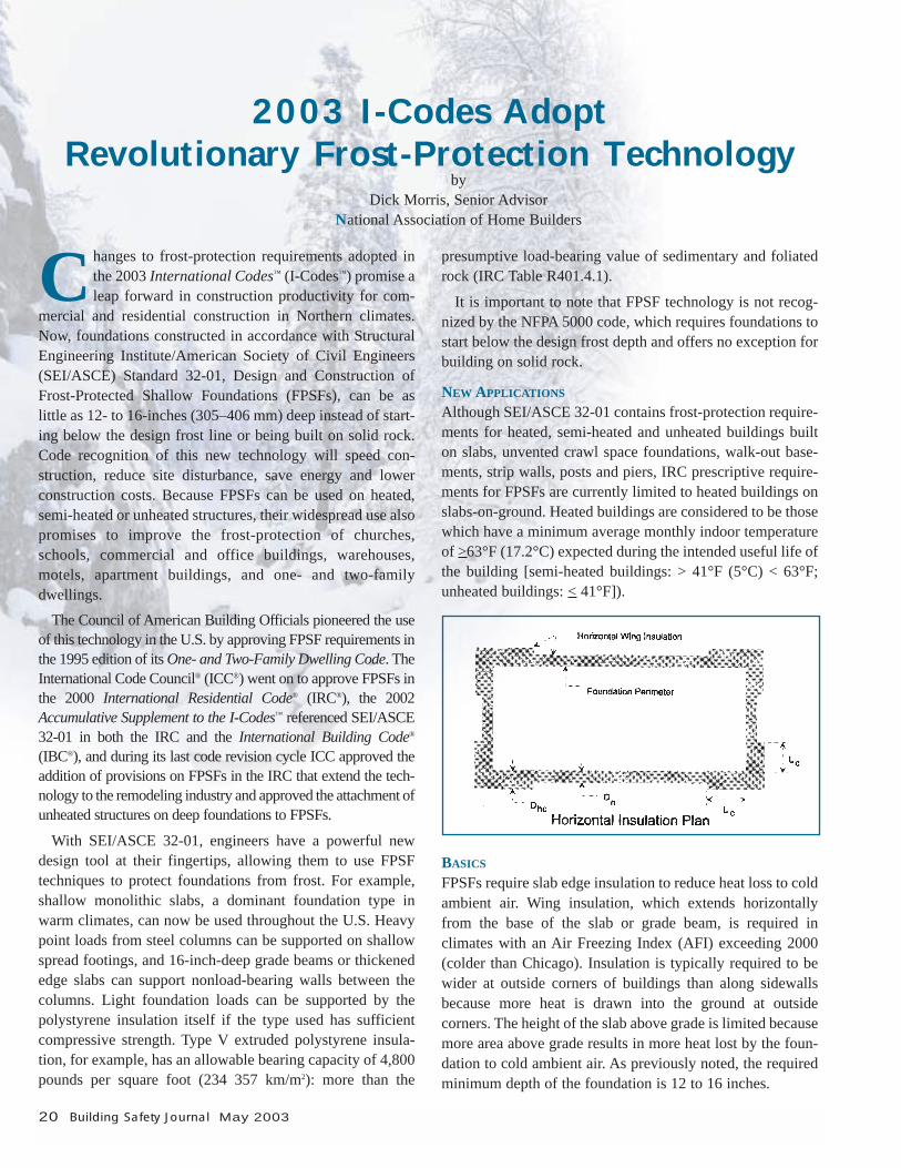
FPSFs require slab edge insulation to reduce heat loss to coldambient air. Wing insulation, which extends horizontallyfrom the base of the slab or grade beam, is required in climates with an Air Freezing Index (AFI) exceeding 2000(colder than Chicago). Insulation is typically required to bewider at outside corners of buildings than along sidewallsbecause more heat is drawn into the ground at outside corners. The height of the slab above grade is limited becausemore area above grade results in more heat lost by the foun-dation to cold ambient air. As previously noted, the requiredminimum depth of the foundation is 12 to 16 inches.
2003 I-Codes AdoptRevolutionary Frost-Protection Technology
byDick Morris, Senior Advisor
National Association of Home Builders
May 2003 Building Safety Journal 21
A Performance StandardIn many ways, SEI/ASCE 32-01 is a performance standard.It permits designers to: • use an “approved design . . . supported by engineering anal-
ysis” (Section 4.1, paragraph 3);
• substitute nonfrost-susceptible fill for increased foundationdepth (Section 4.2);
• vary the height above ground up to 24 inches (610 mm) andthe R-value of sub-slab insulation up to R-28 (Table A4);
• eliminate wing insulation along walls and at corners or usecorner insulation only by increasing foundation depth orusing nonfrost-susceptible fill under the foundation (TableA5); and
• trade off the width and R-value of horizontal wing insula-tion (Table A6).
CLIMATE DATA
The Air Freezing Index is a measure of how cold a climate is,and is used to determine insulation requirements. The 100-year return period value AFI (F100) given by IRC FigureR403.3(2), SEI/ASCE 32-01 Figure A1 or in the far right column of the tables located at http://lwf.ncdc.noaa.gov/oa/fpsf (AFIs for over 3,000 U.S. weather stations) may be used. Mean Annual Temperature (MAT) is used in deter-mining insulation requirements for FPSFs for unheatedbuildings. MAT values can be found in SEI/ASCE 32-01Figure A2 and the AFI tables appearing on the NationalClimate Data Center website above.
GENERAL REQUIREMENTS
SEI/ASCE 32-01 Section 4.1 requires that:• soil and insulation have adequate bearing capacity;• foundation depth be greater than that required by the
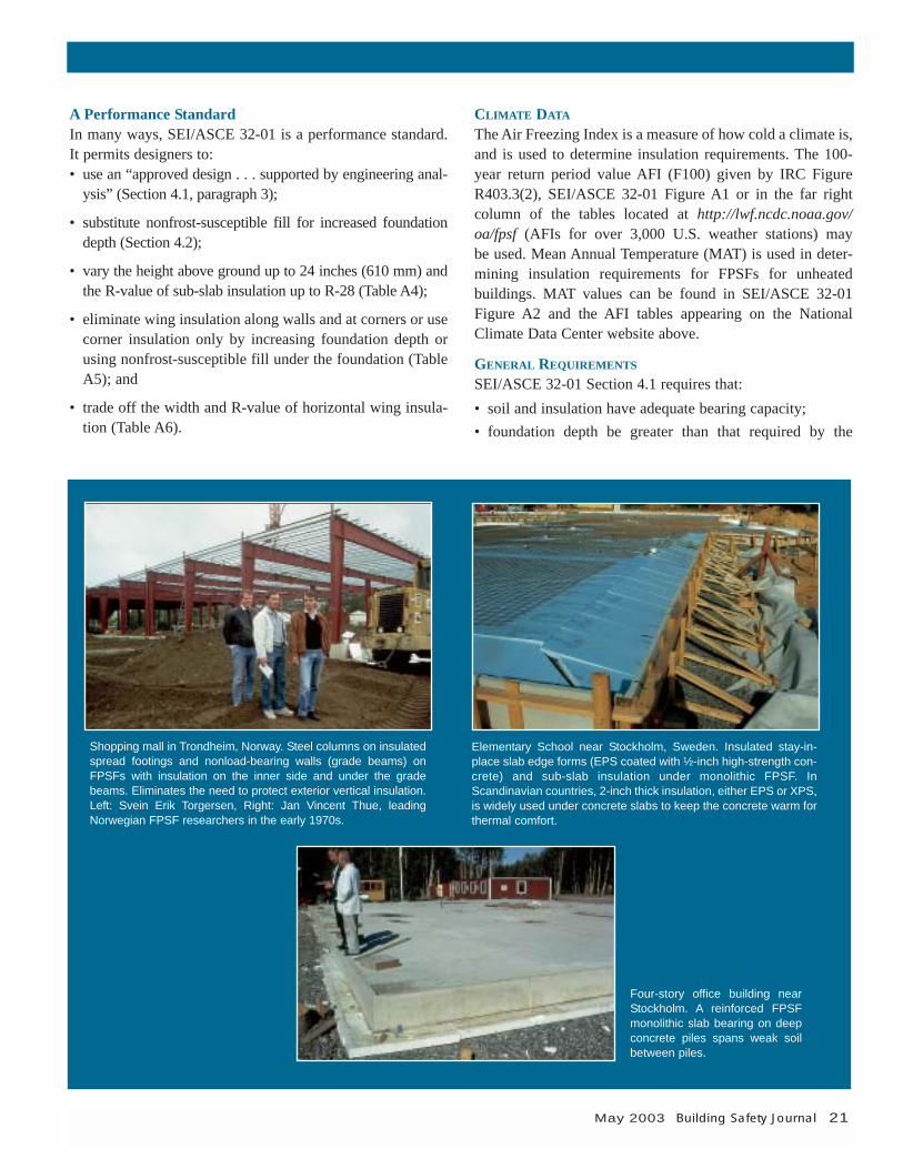
Shopping mall in Trondheim, Norway. Steel columns on insulatedspread footings and nonload-bearing walls (grade beams) onFPSFs with insulation on the inner side and under the gradebeams. Eliminates the need to protect exterior vertical insulation.Left: Svein Erik Torgersen, Right: Jan Vincent Thue, leadingNorwegian FPSF researchers in the early 1970s.
Elementary School near Stockholm, Sweden. Insulated stay-in-place slab edge forms (EPS coated with ½-inch high-strength con-crete) and sub-slab insulation under monolithic FPSF. InScandinavian countries, 2-inch thick insulation, either EPS or XPS,is widely used under concrete slabs to keep the concrete warm forthermal comfort.
Four-story office building nearStockholm. A reinforced FPSFmonolithic slab bearing on deepconcrete piles spans weak soilbetween piles.
22 Building Safety Journal May 2003
standard or for adequate bearing (but not less than 12 inches);
• the site be sloped to drain surface water away from thebuilding;
• stone layer under the insulation be drained to daylight or to an approved foundation drainage system, except in naturally draining soil;
• fill material more than 12-inches thick under foundationsbe compacted;
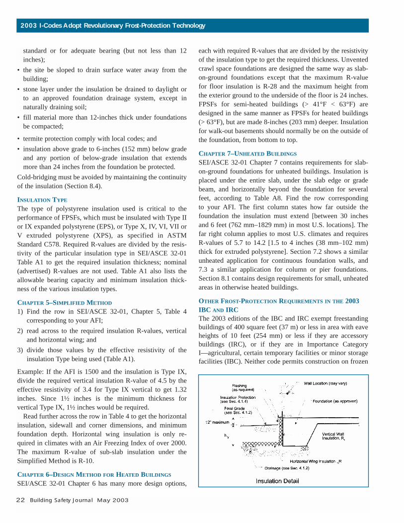
• termite protection comply with local codes; and• insulation above grade to 6-inches (152 mm) below grade
and any portion of below-grade insulation that extendsmore than 24 inches from the foundation be protected.
Cold-bridging must be avoided by maintaining the continuityof the insulation (Section 8.4).
INSULATION TYPE
The type of polystyrene insulation used is critical to the performance of FPSFs, which must be insulated with Type IIor IX expanded polystyrene (EPS), or Type X, IV, VI, VII orV extruded polystyrene (XPS), as specified in ASTMStandard C578. Required R-values are divided by the resis-tivity of the particular insulation type in SEI/ASCE 32-01Table A1 to get the required insulation thickness; nominal(advertised) R-values are not used. Table A1 also lists theallowable bearing capacity and minimum insulation thick-ness of the various insulation types.
CHAPTER 5–SIMPLIFIED METHOD
1) Find the row in SEI/ASCE 32-01, Chapter 5, Table 4 corresponding to your AFI;
2) read across to the required insulation R-values, verticaland horizontal wing; and
3) divide those values by the effective resistivity of the insulation Type being used (Table A1).
Example: If the AFI is 1500 and the insulation is Type IX,divide the required vertical insulation R-value of 4.5 by theeffective resistivity of 3.4 for Type IX vertical to get 1.32inches. Since 1½ inches is the minimum thickness for vertical Type IX, 1½ inches would be required.
Read further across the row in Table 4 to get the horizontalinsulation, sidewall and corner dimensions, and minimumfoundation depth. Horizontal wing insulation is only re-quired in climates with an Air Freezing Index of over 2000.The maximum R-value of sub-slab insulation under theSimplified Method is R-10.
CHAPTER 6–DESIGN METHOD FOR HEATED BUILDINGS
SEI/ASCE 32-01 Chapter 6 has many more design options,
each with required R-values that are divided by the resistivityof the insulation type to get the required thickness. Unventedcrawl space foundations are designed the same way as slab-on-ground foundations except that the maximum R-value for floor insulation is R-28 and the maximum height from the exterior ground to the underside of the floor is 24 inches.FPSFs for semi-heated buildings (> 41°F < 63°F) aredesigned in the same manner as FPSFs for heated buildings (> 63°F), but are made 8-inches (203 mm) deeper. Insulationfor walk-out basements should normally be on the outside ofthe foundation, from bottom to top.
CHAPTER 7–UNHEATED BUILDINGS
SEI/ASCE 32-01 Chapter 7 contains requirements for slab-on-ground foundations for unheated buildings. Insulation isplaced under the entire slab, under the slab edge or gradebeam, and horizontally beyond the foundation for severalfeet, according to Table A8. Find the row corresponding to your AFI. The first column states how far outside the foundation the insulation must extend [between 30 inchesand 6 feet (762 mm–1829 mm) in most U.S. locations]. Thefar right column applies to most U.S. climates and requiresR-values of 5.7 to 14.2 [1.5 to 4 inches (38 mm–102 mm)thick for extruded polystyrene]. Section 7.2 shows a similarunheated application for continuous foundation walls, and7.3 a similar application for column or pier foundations.Section 8.1 contains design requirements for small, unheatedareas in otherwise heated buildings.
OTHER FROST-PROTECTION REQUIREMENTS IN THE 2003IBC AND IRCThe 2003 editions of the IBC and IRC exempt freestandingbuildings of 400 square feet (37 m) or less in area with eaveheights of 10 feet (254 mm) or less if they are accessorybuildings (IRC), or if they are in Importance Category I—agricultural, certain temporary facilities or minor storagefacilities (IBC). Neither code permits construction on frozen
2003 I-Codes Adopt Revolutionary Frost-Protection Technology
soil unless it is “of a permanent character” (permafrost).Unlike the IBC, Section R403.3 of the IRC contains pre-scriptive language for FPSFs for heated slab-on-groundbuildings.
UNHEATED ATTACHMENTS (e.g. GARAGES, PORCHES)New in the 2003 IRC are requirements for the attachment ofhomes on FPSFs to unheated slab-on-ground structures withdeep foundations. In these, the vertical insulation on theFPSF and any horizontal wing insulation required must continue uninterrupted under the garage floor or porch slabas well as through foundation walls of the adjoining struc-ture. Any load on horizontal wing insulation can be carriedby using insulation with high compressive strength or bybridging over the insulation with lintels, beams or can-tilevers built into the walls of the adjoining structure.
FPSF ADDITIONSAlso permitted in the 2003 IRC are heated additions built onFPSFs that are attached to heated buildings. Insulationbetween the addition and building is not required. In climates over 2000 AFI and where the addition is in linewith the outside corner of a building, the vertical and hori-zontal insulation of the FPSF addition is required to contin-ue onto the existing building a distance equal to the width ofhorizontal sidewall insulation (dimension A in IRC TableR403.3). ◆
FPSF Requirements Supported by a Half-Century of R&D
The roots of frost-protected shallow foundations (FPSFs) maylie in Frank Lloyd Wright’s Usonian houses of the 1930s.Wright used shallow foundations built on rock-filled trenches;in-slab heating provided warmth to the ground and raised thefrost-line around the buildings.
World War II saw development of polystyrene foam insula-tion for flotation devices, and insulation board followed.William Levitt and others popularized slab-on-ground founda-tions in cold climates. The foundations had perimeter heat ductswhich supplied heat to the soil.
In 1947, research by the American Society of Heating andVentilating Engineers (the predecessor of the American Societyof Heating, Refrigeration and Air-conditioning Engineers)showed a “heat bulb” of warm soil that builds up under slabfoundations and supplies heat to the perimeter of the foundation.Scandinavian research added polystyrene slab-edge insulationto retain this heat and raise the frost line around buildings.Decades of research, construction and computer modeling led toacceptance of FPSF technology in the Swedish building code in1968, the Norwegian code in 1972 and the Finnish code in 1978.Well over a million buildings of all types have been built onFPSFs in the Nordic countries over the past half-century.
In the U.S., the NAHB Research Center began exploring thetechnique in 1984. The Society of the Plastics Industry pro-vided funding for a background study. Later, Peter Steuerworked on behalf of the U.S. Department of CommerceNational Oceanic and Atmospheric Administration’s NationalClimatic Data Center to develop Air Freezing Index maps andtables with the Research Center’s Jay Crandell. The U.S.Department of Housing and Urban Development then fundedthe monitoring of five demonstration houses and preparation ofa design guide, under lead investigator, Jay Crandell. ◆
SUGGESTED PLAN REVIEW ANDINSPECTION PLAN REVIEW
• Verify design conditions—heated, semi-heated and unheated spaces.
• Check foundation depths for each type, and depth of nonfrost-susceptible fill.
• Determine ASTM C578 Insulation Type being used.• Verify Air Freezing Index for the building site.• Check calculations and verify insulation dimensions,
continuity and compressive strength.• Verify that insulation meets energy code.• Check drainage plan and termite precautions.
ON-SITE INSPECTION
✓ Insulation Types (per ASTM C578)✓ Insulation dimensions and continuity✓ Foundation depths and non-frost-susceptible fill depths✓ Distance from top of slab to grade✓ Protection of insulation✓ Termite precautions✓ Drainage
Dick Morris has been employed with the NationalAssociation of Home Builders (NAHB) Construction,Codes and Standards Department since 1988, prior towhich he was with the NAHB Research Center, where heinitiated research into frost-protected shallow foundationsthat led to code development in this area.
Morris served on the consensus committee that wroteSEI/ASCE Standard 32-01, Frost-Protected ShallowFoundations. He now manages the www.NAHB.org webpage on Frost-Protected Shallow Foundations (www.nahb.org/reference_list.aspx?section ID=235).
May 2003 Building Safety Journal 23
24 Building Safety Journal May 2003
Prior to the Second World War, crawl space con-
struction in the U.S. was predominately a
Southern phenomenon in which houses were
elevated several feet above ground, supported by block
or stone piers. Damp soil conditions and problems with
termites are thought to be the primary reasons for using
this foundation method. In the Northern region of the
country, crawl spaces were usually limited to portions
of the foundation that were located below porches or
additions, and often opened into a basement.
During and after WWII, efforts to decrease the cost of
foundations and houses led to an increase in the con-
struction of crawl spaces in many parts of the U.S. The
majority of these crawl spaces were excavated below
the exterior grade and contained air distribution ducts
and air handlers. This increase in crawl space construc-
tion was quickly followed by reports of moisture prob-
lems in the floors above crawl spaces and in the attics
of houses with crawl spaces. Moisture problems related
to crawl space construction continue to occur in new
homes using this type of foundation.
History of Building Code RequirementsOver the past 50 years, building code requirements for crawlspace construction have evolved largely in the absence ofresearch or a basis in moisture physics. According to Rose(1994) the first requirement for crawl space ventilationappeared in a 1942 publication by the Federal HousingAdministration entitled Property Standards and MinimumConstruction Requirements for Dwellings. The requirementwas for “a total ventilating area equivalent to ½ percent of
the enclosed area plus ½ square foot for each 25 lineal feet ofwall enclosing that area.”
While working for the Housing and Home FinanceAgency, Ralph Britton investigated moisture problems inhousing with crawl spaces. He recognized two strategies forcontrolling crawl space moisture: condensation control byventilation, and condensation control by ground cover.However, neither Britton nor anyone else at the time deter-mined the relative contributions made by ventilation versusground cover. The majority of ground covers available during the 1940s and early 1950s were not very durable, soventilation of crawl spaces was probably recommended evenin the presence of a ground cover as a permanent back-upsystem. By the mid-1950s, the durability of polyethylenesheeting had been proven and many building codes beganrequiring a ground cover in crawl spaces in addition to vent-ing to the exterior.
Problems with Current Crawl Space ConstructionThere are three characteristics typical of homes built overcrawl spaces and which have moisture problems: excavatedcrawl space floor without effective drainage, absent or poorlyinstalled ground cover, and exterior venting. Moisture prob-lems and poor indoor air quality continue to affect new build-ings constructed over crawl spaces. Some of these problemsare the result of poor workmanship and maintenance, but others are the result of poor design and a lack of understand-ing of moisture dynamics. Ground covers are frequentlyinstalled incorrectly in that they are not continuous or sealedto the perimeter walls and piers. The floors of crawl spacesare often irregular and littered with sharp rocks and con-struction debris so that proper installation of the groundcover is virtually impossible. Subsequent work occurring inthe crawl space often results in tears in the ground cover,allowing ground moisture into the crawl space air. Becausethis under-floor space is not considered “habitable” or“usable,” most crawl spaces are not provided with effectivedrainage.
Few designers, contractors and homeowners understandthe connection between a crawl space and the living spaceabove. Even when insulation is carefully installed to theunderside of the floor above a crawl space, effective air-sealing is rarely accomplished. Penetrations for plumbing,
The Case for Conditioned, Unvented Crawl Spaces
by Dr. Nathan Yost, M.D.
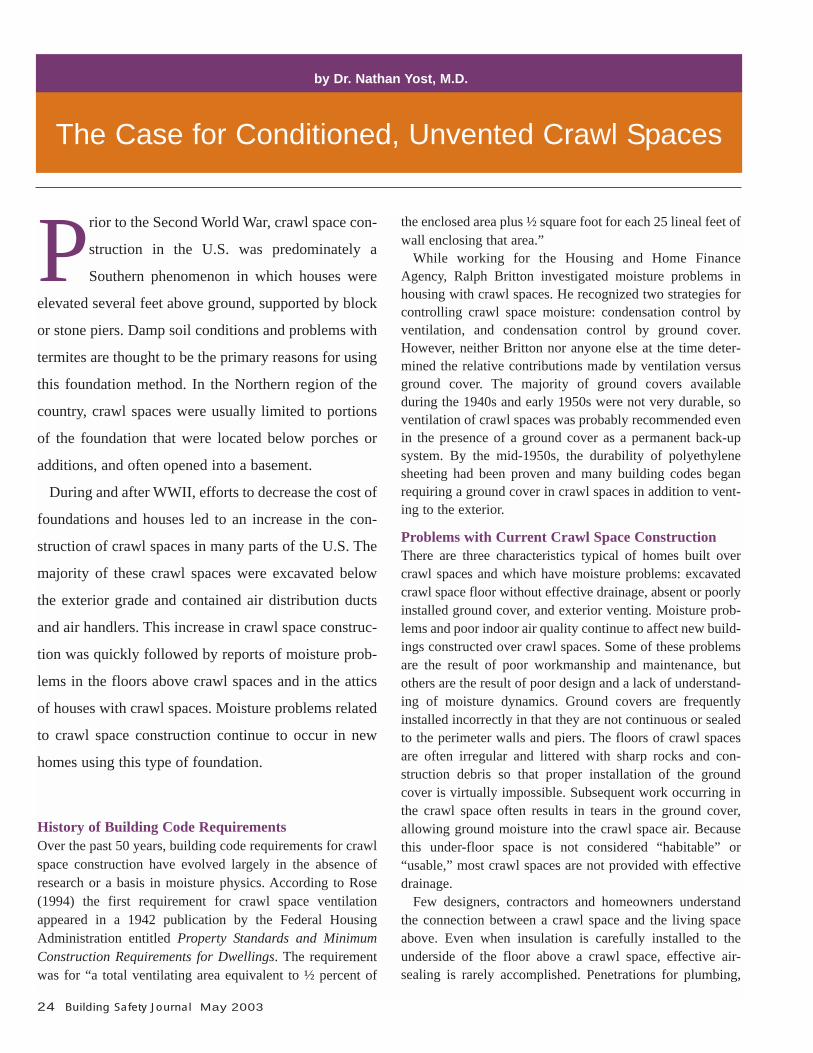
wiring and air ducts provide multiple pathways for crawlspace air to enter the living space. During heating periods,the “stack effect” can easily draw crawl space air up into thestructure above. Leakage from supply ducts in the attic cancause the air pressure inside the house to become lower thanthat in the crawl space. Because of this pressure differential,air containing moisture and other contaminants from thecrawl space can then enter the house. (see Figure 1).
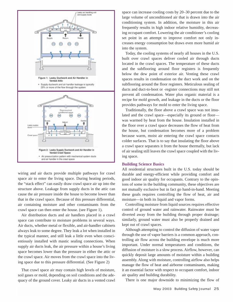
Air distribution ducts and air handlers placed in a crawlspace can contribute to moisture problems in several ways.Air ducts, whether metal or flexible, and air-handler cabinetsalways leak to some degree. They leak a lot when installed inthe typical manner, and still leak a little even when consci-entiously installed with mastic sealing connections. Whensupply air ducts leak, the air pressure within a house’s livingspace becomes lower than the pressure in either the attic orthe crawl space. Air moves from the crawl space into the liv-ing space due to this pressure differential. (See Figure 2)
That crawl space air may contain high levels of moisture,soil gases or mold, depending on soil conditions and the ade-quacy of the ground cover. Leaky air ducts in a vented crawl
space can increase cooling costs by 20–30 percent due to thelarge volume of unconditioned air that is drawn into the airconditioning system. In addition, the moisture in this air frequently results in high indoor relative humidity, decreas-ing occupant comfort. Lowering the air conditioner’s coolingset point in an attempt to improve comfort not only in-creases energy consumption but draws even more humid airinto the system.
Today, the cooling systems of nearly all houses in the U.S.built over crawl spaces deliver cooled air through ductslocated in the crawl spaces. The temperature of these ductsand the subflooring around floor registers is frequentlybelow the dew point of exterior air. Venting these crawlspaces results in condensation on the duct work and on thesubflooring around the floor registers. Meticulous sealing ofducts and duct-to-boot or -register connections may still notprevent all condensation. Water plus organic material is arecipe for mold growth, and leakage in the ducts or the floorprovides pathways for mold to enter the living space.
Traditionally, the floor above a crawl space was not insu-lated and the crawl space—especially its ground or floor—was warmed by heat from the house. Insulation installed inthe floor over a crawl space decreases the flow of heat fromthe house, but condensation becomes more of a problembecause warm, moist air entering the crawl space contactscolder surfaces. That is to say that insulating the floor abovea crawl space separates it from the house thermally, but lackof air sealing still leaves the crawl space coupled with the liv-ing space.
Building Science BasicsAll residential structures built in the U.S. today should bedurable and energy-efficient while providing comfort andgood indoor air quality for occupants. Contrary to the opin-ions of some in the building community, these objectives arenot mutually exclusive but in fact go hand-in-hand. Meetingthese goals requires controlling the flow of heat, air andmoisture—in both its liquid and vapor forms.
Controlling moisture from liquid sources requires effectivecontrol of ground water and rainwater. Rainwater must bediverted away from the building through proper drainage;similarly, ground water must also be properly drained andkept out of crawl spaces.
Although attempting to control the diffusion of water vaporthrough the use of vapor barriers is a common approach, con-trolling air flow across the building envelope is much moreimportant. Under normal temperatures and conditions, thediffusion of moisture is a slow process. Airflow, however, canquickly deposit large amounts of moisture within a buildingassembly. Along with moisture, controlling airflow also helpsmanage the flow of heat and airborne contaminants, makingit an essential factor with respect to occupant comfort, indoorair quality and building durability.
There is one major downside to minimizing the flow of
May 2003 Building Safety Journal 25
26 Building Safety Journal May 2003
heat and air: a reduction in the rate at which building assem-blies dry when they get wet. Although every effort should bemade to prevent wetting of buildings, it is inevitable thatsome will occur. As such, building assemblies should bedesigned not just to minimize wetting, but also to maximizedrying of the interior, exterior or both.
Recommended Crawl Space ConstructionLocal climate conditions should always influence decisionsabout design, materials and construction methods. From abuilding science perspective, the two fundamental ways tobuild a house over a crawl space are unconditioned and vented, with the thermal boundary and the pressure (air)boundary at the bottom of the floor of the living space; orconditioned and unvented, with the thermal and pressureboundaries at the perimeter of the crawl space. There are twomajor factors to consider when determining which designapproach is appropriate. Is duct work or an air handler locat-ed in the crawl space, and can the floor of the crawl space beeffectively air-sealed at the appropriate time? If under-floorduct work or an air handler is located in the crawl space thena conditioned, unvented crawl space is the preferred method.If no mechanical system is located in the crawl space, theneither option will work.
The emphasis is on conditioning the crawl space becausewhen conditioned, there is no need to vent them. Alternatively,when crawl spaces are vented there must be effective air-sealing between the crawl space and the conditioned spaceabove.
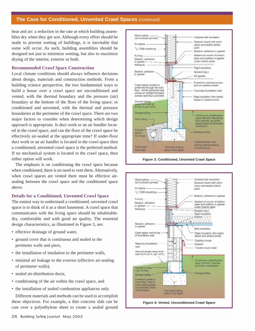
Details for a Conditioned, Unvented Crawl SpaceThe easiest way to understand a conditioned, unvented crawlspace is to think of it as a short basement. A crawl space thatcommunicates with the living space should be inhabitable:dry, comfortable and with good air quality. The essentialdesign characteristics, as illustrated in Figure 3, are:
• effective drainage of ground water,
• ground cover that is continuous and sealed to the perimeter walls and piers,
• the installation of insulation to the perimeter walls,
• minimal air leakage to the exterior (effective air-sealingof perimeter walls),
• sealed air-distribution ducts,
• conditioning of the air within the crawl space, and
• the installation of sealed combustion appliances only. Different materials and methods can be used to accomplish
these objectives. For example, a thin concrete slab can becast over a polyethylene sheet to create a sealed ground
Figure 3: Conditioned, Unvented Crawl Space
Figure 4: Vented, Unconditioned Crawl Space
The Case for Conditioned, Unvented Crawl Spaces (continued)
May 2003 Building Safety Journal 27
cover. Water in construction materials can contribute tomoisture problems in crawl spaces, so a low water-to-cementratio (0.45 or less) is recommended. Concrete with higherwater content may require supplemental dehumidification inthe crawl space for 6 to 12 months to prevent fungal growthon wood framing.
A small amount of conditioned air can be supplied to thecrawl space with passive return through floor registers.Alternatively, air can be continuously exhausted from thecrawl space, thus ensuring that soil gases or contaminants inthe crawl space do not reach the living space. In this situa-tion, the crawl space will be conditioned by air that movesfrom the living space because of the pressure differential cre-ated by the crawl space exhaust fan.
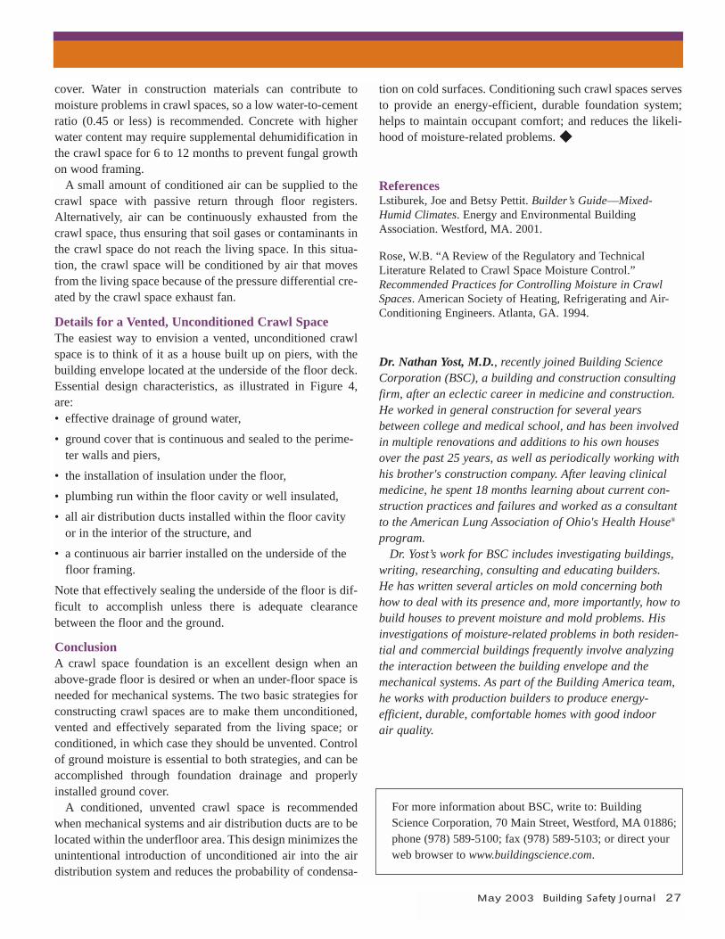
Details for a Vented, Unconditioned Crawl SpaceThe easiest way to envision a vented, unconditioned crawlspace is to think of it as a house built up on piers, with thebuilding envelope located at the underside of the floor deck.Essential design characteristics, as illustrated in Figure 4,are:• effective drainage of ground water,
• ground cover that is continuous and sealed to the perime-ter walls and piers,
• the installation of insulation under the floor,
• plumbing run within the floor cavity or well insulated,
• all air distribution ducts installed within the floor cavityor in the interior of the structure, and
• a continuous air barrier installed on the underside of thefloor framing.
Note that effectively sealing the underside of the floor is dif-ficult to accomplish unless there is adequate clearancebetween the floor and the ground.
ConclusionA crawl space foundation is an excellent design when anabove-grade floor is desired or when an under-floor space isneeded for mechanical systems. The two basic strategies forconstructing crawl spaces are to make them unconditioned,vented and effectively separated from the living space; orconditioned, in which case they should be unvented. Controlof ground moisture is essential to both strategies, and can beaccomplished through foundation drainage and properlyinstalled ground cover.
A conditioned, unvented crawl space is recommendedwhen mechanical systems and air distribution ducts are to belocated within the underfloor area. This design minimizes theunintentional introduction of unconditioned air into the airdistribution system and reduces the probability of condensa-
tion on cold surfaces. Conditioning such crawl spaces servesto provide an energy-efficient, durable foundation system;helps to maintain occupant comfort; and reduces the likeli-hood of moisture-related problems. ◆
ReferencesLstiburek, Joe and Betsy Pettit. Builder’s Guide—Mixed-Humid Climates. Energy and Environmental BuildingAssociation. Westford, MA. 2001.
Rose, W.B. “A Review of the Regulatory and TechnicalLiterature Related to Crawl Space Moisture Control.”Recommended Practices for Controlling Moisture in CrawlSpaces. American Society of Heating, Refrigerating and Air-Conditioning Engineers. Atlanta, GA. 1994.
Dr. Nathan Yost, M.D., recently joined Building ScienceCorporation (BSC), a building and construction consultingfirm, after an eclectic career in medicine and construction.He worked in general construction for several yearsbetween college and medical school, and has been involvedin multiple renovations and additions to his own housesover the past 25 years, as well as periodically working withhis brother's construction company. After leaving clinicalmedicine, he spent 18 months learning about current con-struction practices and failures and worked as a consultantto the American Lung Association of Ohio's Health House®
program.Dr. Yost’s work for BSC includes investigating buildings,
writing, researching, consulting and educating builders. He has written several articles on mold concerning bothhow to deal with its presence and, more importantly, how tobuild houses to prevent moisture and mold problems. Hisinvestigations of moisture-related problems in both residen-tial and commercial buildings frequently involve analyzingthe interaction between the building envelope and themechanical systems. As part of the Building America team,he works with production builders to produce energy-efficient, durable, comfortable homes with good indoorair quality.
For more information about BSC, write to: BuildingScience Corporation, 70 Main Street, Westford, MA 01886;phone (978) 589-5100; fax (978) 589-5103; or direct yourweb browser to www.buildingscience.com.
28 Building Safety Journal May 2003
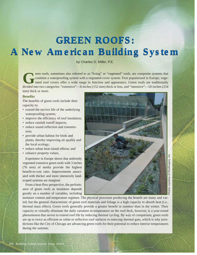
Green roofs, sometimes also referred to as “living” or “vegetated” roofs, are composite systems thatcombine a waterproofing system with a vegetated-cover system. First popularized in Europe, vege-tated roof covers offer a wide range in function and appearance. Green roofs are traditionally
divided into two categories: “extensive”—6-inches (152 mm) thick or less, and “intensive”—10-inches (254mm) thick or more.BenefitsThe benefits of green roofs include theircapacity to:• extend the service life of the underlying
waterproofing system;• improve the efficiency of roof insulation;• reduce rainfall runoff impacts;• reduce sound reflection and transmis-
sion;• provide urban habitat for birds and
plants, thereby improving air quality andthe local ecology;
• reduce urban heat-island effects; and• enhance property values.
Experience in Europe shows that uniformlyvegetated extensive green roofs with 3 inches(76 mm) of media provide the highest benefit-to-cost ratio. Improvements associ-ated with thicker and more intensively land-scaped systems are marginal.
From a heat-flow perspective, the perform-ance of green roofs as insulators dependsgreatly on a number of variables, includingmoisture content and temperature regimen. The physical processes producing the benefit are many and var-ied, but the general characteristic of green roof materials and foliage is a high capacity to absorb heat (i.e.,thermal mass effect). Green roofs generally provide a greater benefit in summer than in the winter. Theircapacity to virtually eliminate the daily variation in temperature on the roof deck, however, is a year-roundphenomenon that serves to extend roof life by reducing thermal cycling. By way of comparison, green roofsare up to twice as efficient as white or reflective roof surfaces in reducing thermal gain, which is why juris-dictions like the City of Chicago are advancing green roofs for their potential to reduce interior temperaturesduring the summer.
GREEN ROOFS:A New American Building System
GREEN ROOFS:A New American Building System
by Charles D. Miller, P.E.
Phot
os c
ourte
sy o
f Roo
fsca
pes,
Inc.
Green roofs also produce a dramatic reduction inboth the quantity of rainfall runoff and the rate ofrunoff.1 This benefit has spurred the widespreadimplementation of green roofs in Germany. On anannual basis, rainfall runoff quantity will bereduced by 60 percent or more in most regions, witha similar reduction in runoff rate. To the extent thatgreen roofs can reduce runoff rate, other deviceslike stormwater basins, below-grade detention stor-age, etc., can be reduced in size or eliminated. Inurbanized areas the potential savings are three-fold:reduced site-development costs, increased commer-cial space (which would otherwise be consumed bystormwater detention basins) and lower publicinfrastructure demands for stormwater mitigationstrategies.
Standards and Guidelines Because the market in the U.S. for green roofs is inits infancy, most Americans are unfamiliar withthem. The combination of few companies withextensive installation experience and the large num-ber of different systems now entering the marketcan make it difficult to obtain good informationabout green roof systems. Evaluating the claims ofdifferent providers and making meaningful compar-isons between products can be challenging, espe-cially since there are not yet any accepted standardsor measures of performance to reference.
In the absence of American standards, many greenroof customers rely on the guidelines and standardsdeveloped in Germany. In particular, the detailedstandards and guidelines published by FLL2 covermost aspects of green roof design. These includetests and standards for assessing the root resistanceof waterproofing materials, determining the waterretention properties of growing media, predictingthe maximum weight of green roof systems, ensur-ing adequate drainage capacity, etc. These standardsare most appropriately applied in northern temperateareas of North American. Several groups, mostnotably ASTM International, are working to adoptstandards that will be more broadly applicablethroughout the U.S. (see sidebar).Weight ConsiderationsIt is not difficult to design green roof systems thathave a maximum weight of less than 13 pounds persquare foot (36.5 kg/m2). However, green roofs
weighing 18 pounds per square foot (87.9 kg/m2) ormore are most common. Many buildings construc-ted prior to 1960 incorporated conventional roofingsystems that included layers of felt and asphalttopped with stone ballast. Depending on the local-ity, these roofing systems weigh 10–15 pounds persquare foot (48.8–73.2 kg/m2). As a result, it is oftenpossible to remove existing waterproofing systemsand replace them with green roofs without having toresort to structural reinforcement of the roof deck.
The weight of a green roof system includes theweight of all its components. In order of decreasingcontribution to overall load, they include the growingmedium, plants, water retention, waterproofing, andsynthetic components such as fabrics and membranes
The guidelines set forth in the InternationalCodes™ treat the weight of a green roof, includingall retained moisture, as a dead load. How shouldthis weight be determined in the absence of anAmerican standard procedure? The FLL specifies alaboratory test to assess the maximum weight con-tributed by the media. The test involves compress-ing the material into a mold with a 10-poundProctor hammer, immersing the sample for 24 hoursand then draining it briefly before measuring itsweight. Due to the conservative nature of this test, Irecommend using it to evaluate the structural ade-quacy of roof structures.
In extensive green roofs the weight of plantfoliage, laden with moisture, rarely exceeds 2pounds per square foot (9.8 kg/m2). However, whendesigning intensive green roofs with large shrubsand trees, careful consideration must be given to themature weight of such plants. During and immedi-ately following rainfall, water will accumulate in thedrainage layers of green roofs. This temporaryincrease in weight might be more appropriatelyaddressed as a live load. However, in green roofdesign it is usually included in the calculation ofdead load. This load factor may vary widely amongdifferent green roof systems and should be specifiedby the system provider. The dead load associatedwith the green roofs must be added to appropriatelive loads such as snow, wind and human foot trafficto evaluate the feasibility of a green roof design. TheInternational Codes provide guidelines for assign-ing these loads appropriately.
May 2003 Building Safety Journal 29
(continued)
30 Building Safety Journal May 2003
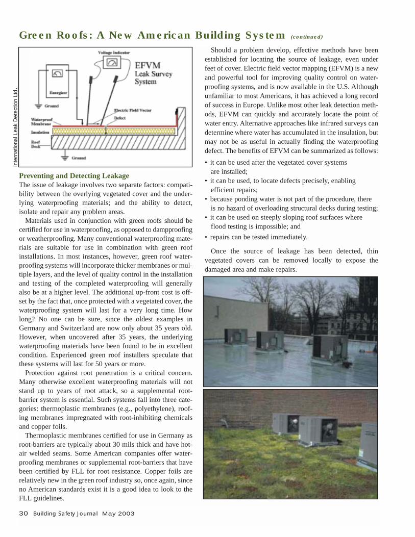
Preventing and Detecting LeakageThe issue of leakage involves two separate factors: compati-bility between the overlying vegetated cover and the under-lying waterproofing materials; and the ability to detect, isolate and repair any problem areas.
Materials used in conjunction with green roofs should becertified for use in waterproofing, as opposed to dampproofingor weatherproofing. Many conventional waterproofing mate-rials are suitable for use in combination with green roofinstallations. In most instances, however, green roof water-proofing systems will incorporate thicker membranes or mul-tiple layers, and the level of quality control in the installationand testing of the completed waterproofing will generallyalso be at a higher level. The additional up-front cost is off-set by the fact that, once protected with a vegetated cover, thewaterproofing system will last for a very long time. Howlong? No one can be sure, since the oldest examples inGermany and Switzerland are now only about 35 years old.However, when uncovered after 35 years, the underlyingwaterproofing materials have been found to be in excellentcondition. Experienced green roof installers speculate thatthese systems will last for 50 years or more.
Protection against root penetration is a critical concern.Many otherwise excellent waterproofing materials will notstand up to years of root attack, so a supplemental root-barrier system is essential. Such systems fall into three cate-gories: thermoplastic membranes (e.g., polyethylene), roof-ing membranes impregnated with root-inhibiting chemicalsand copper foils.
Thermoplastic membranes certified for use in Germany asroot-barriers are typically about 30 mils thick and have hot-air welded seams. Some American companies offer water-proofing membranes or supplemental root-barriers that havebeen certified by FLL for root resistance. Copper foils arerelatively new in the green roof industry so, once again, sinceno American standards exist it is a good idea to look to theFLL guidelines.
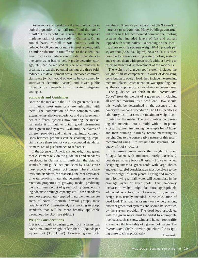
Should a problem develop, effective methods have beenestablished for locating the source of leakage, even underfeet of cover. Electric field vector mapping (EFVM) is a newand powerful tool for improving quality control on water-proofing systems, and is now available in the U.S. Althoughunfamiliar to most Americans, it has achieved a long recordof success in Europe. Unlike most other leak detection meth-ods, EFVM can quickly and accurately locate the point ofwater entry. Alternative approaches like infrared surveys candetermine where water has accumulated in the insulation, butmay not be as useful in actually finding the waterproofingdefect. The benefits of EFVM can be summarized as follows:• it can be used after the vegetated cover systems
are installed;• it can be used, to locate defects precisely, enabling
efficient repairs;• because ponding water is not part of the procedure, there
is no hazard of overloading structural decks during testing;• it can be used on steeply sloping roof surfaces where
flood testing is impossible; and• repairs can be tested immediately.
Once the source of leakage has been detected, thin vegetated covers can be removed locally to expose the damaged area and make repairs.
Green Roofs: A New American Building System (continued)
Inte
rnat
iona
l Lea
k D
etec
tion
Ltd.
May 2003 Building Safety Journal 31
ConclusionWhen appropriately designed and constructed, green roofsare extremely durable roofing systems. Hopefully, we willsee more widespread acceptance of these systems in the U.S.and the development of appropriate American standards inthe near future. Until these systems become more familiar toAmerican builders, however, it is prudent to rely on thestandards and guidelines which have been developed inEurope over the past 40 years. ◆
Notes1.Miller, C, and Pyke, G., Methodology for the Design of
Vegetated Roof Covers, Proceedings of the 1999International Water Resource Engineering Conference,American Society of Civil Engineers.
2.Forschungsgesellschaft LandschaftsentwicklungLandschaftsbau e.V. (Landscaping and LandscapeDevelopment and Research Society), Richtlinien für diePlannung, Ausführung und Pflege von Dachbegrünung(Guidelines for the Planning, Installation andMaintenance of Green Roofs), 1995.
Charles D. Miller, P.E., is a member of the TechnicalAdvisory Committees for the Center for Green RoofResearch at the Pennsylvania State University and theGreen Roofs for Healthy Cities Coalition, a Toronto-basedresearch and public policy organization. He is also a mem-ber of the ASTM Subcommittee E06.71 on Sustainability,Buildings; and the German Roof-Gardening Association.
Miller is the founder and president of Roofscapes, Inc.,which offers the Roofmeadow® family of green roof systemsthrough its national network of licensed green roofinstallers. For more information, write to Roofscapes, Inc.,at 7114 McCallum Street, Philadelphia, PA 19119; phone(215) 247-8784; fax (215) 247-4659; [email protected]; or go to www.roofmeadow.com.
In 2001, ASTM International added a Green Roof TaskGroup to its Subcommittee E06.71 on Performance ofBuildings, Sustainability. The group is charged with thedevelopment of a Standard Practice of the Assessmentof Green Roofs. The resulting standard is intended toaddress both technical requirements and considerationsfor sustainable development.
The members of the task group include a cross-sectionof the green roof industry roofing material specialists,horticulturists and engineers. The group has been usingthe well-established German FLL guidelines as thefoundation for its work, which has recently focused onestablishing a technical basis for assessing the perform-ance characteristics of drainage layers and growthmedia in green roof systems. Particularly challenging isthe problem of extending the European knowledge baseto encompass the diverse regional conditions acrossNorth America. ◆
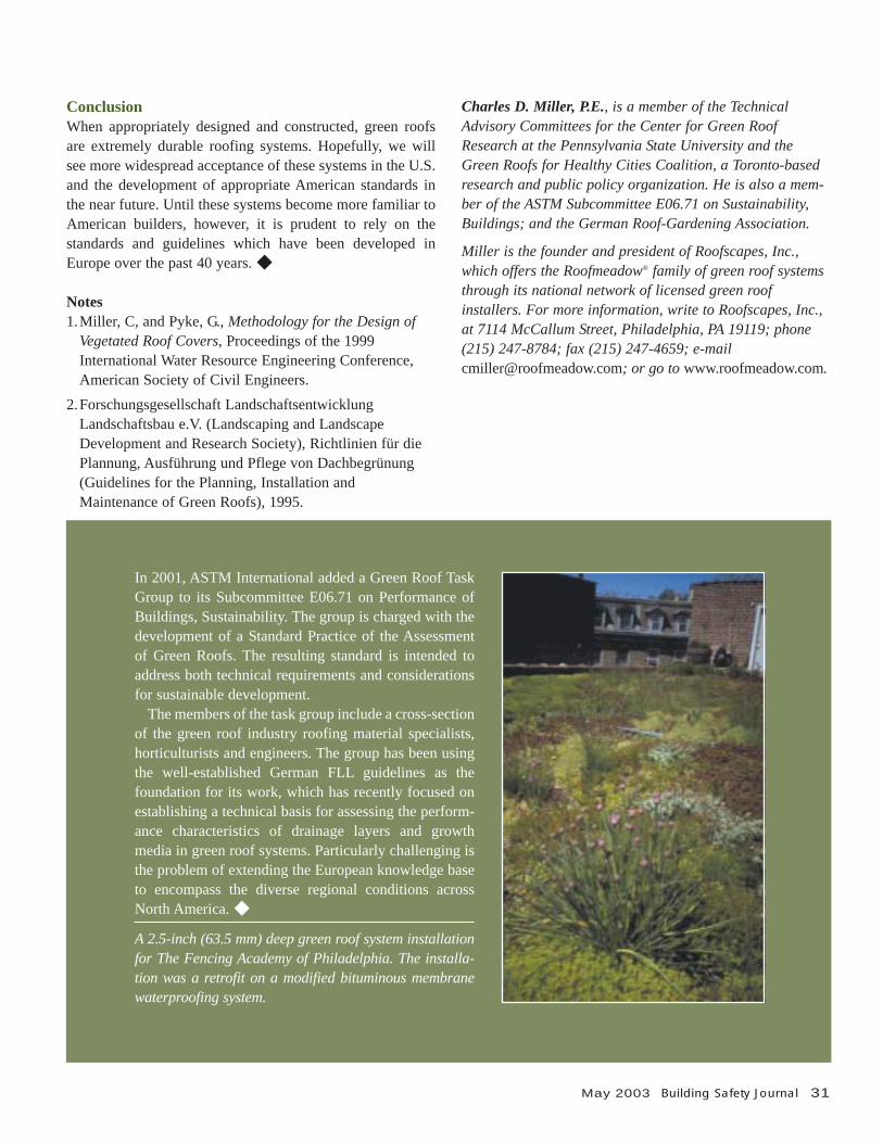
A 2.5-inch (63.5 mm) deep green roof system installationfor The Fencing Academy of Philadelphia. The installa-tion was a retrofit on a modified bituminous membranewaterproofing system.
32 Building Safety Journal May 2003
Various forms of rubbletrench foundationshave been used for
thousands of years. For exam-ple, earthen walls in the MiddleEast and Africa are built on topof shallow ditches filled withloose rock. Frank Lloyd Wrightcame across the rubble trenchfoundation system around theturn of the 20th Century. Heobserved the structures to be“perfectly static” with no signsof heaving, and thereafter builtconsistently with what hetermed “dry wall footing.”Many time-tested structuresstand as testimony to the lon-gevity of the rubble trench.
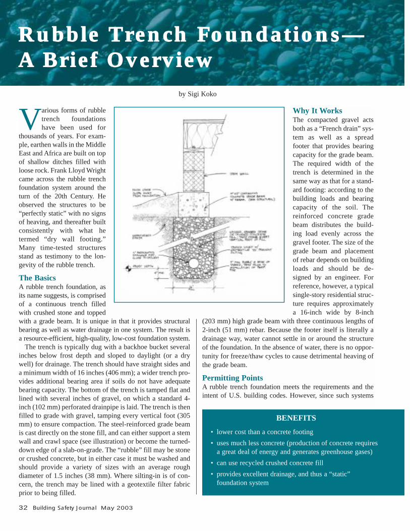
The BasicsA rubble trench foundation, asits name suggests, is comprisedof a continuous trench filledwith crushed stone and toppedwith a grade beam. It is unique in that it provides structuralbearing as well as water drainage in one system. The result isa resource-efficient, high-quality, low-cost foundation system.
The trench is typically dug with a backhoe bucket severalinches below frost depth and sloped to daylight (or a drywell) for drainage. The trench should have straight sides anda minimum width of 16 inches (406 mm); a wider trench pro-vides additional bearing area if soils do not have adequatebearing capacity. The bottom of the trench is tamped flat andlined with several inches of gravel, on which a standard 4-inch (102 mm) perforated drainpipe is laid. The trench is thenfilled to grade with gravel, tamping every vertical foot (305mm) to ensure compaction. The steel-reinforced grade beamis cast directly on the stone fill, and can either support a stemwall and crawl space (see illustration) or become the turned-down edge of a slab-on-grade. The “rubble” fill may be stoneor crushed concrete, but in either case it must be washed andshould provide a variety of sizes with an average roughdiameter of 1.5 inches (38 mm). Where silting-in is of con-cern, the trench may be lined with a geotextile filter fabricprior to being filled.
Why It WorksThe compacted gravel actsboth as a “French drain” sys-tem as well as a spread footer that provides bearingcapacity for the grade beam.The required width of thetrench is determined in thesame way as that for a stand-ard footing: according to thebuilding loads and bearingcapacity of the soil. Thereinforced concrete gradebeam distributes the build-ing load evenly across thegravel footer. The size of thegrade beam and placementof rebar depends on buildingloads and should be de-signed by an engineer. Forreference, however, a typicalsingle-story residential struc-ture requires approximatelya 16-inch wide by 8-inch
(203 mm) high grade beam with three continuous lengths of2-inch (51 mm) rebar. Because the footer itself is literally adrainage way, water cannot settle in or around the structureof the foundation. In the absence of water, there is no oppor-tunity for freeze/thaw cycles to cause detrimental heaving ofthe grade beam.
Permitting PointsA rubble trench foundation meets the requirements and theintent of U.S. building codes. However, since such systems
Rubble Trench Foundations—A Brief Overview
by Sigi Koko
BENEFITS
• lower cost than a concrete footing• uses much less concrete (production of concrete requires
a great deal of energy and generates greenhouse gases)• can use recycled crushed concrete fill• provides excellent drainage, and thus a “static”
foundation system
are not specifically addressed in the current codes, accept-ance must be provided on a case-by-case basis. Since thisputs permit approval at the discretion of the individual build-ing official, it is recommended that builders initiate a dia-logue with the building department prior to applying for apermit. Doing so will provide an opportunity to inform andeducate permitting staff as needed and provide adequateinformation to satisfy their desire to ensure a safe structure.It is further recommended that stamped structural drawingsbe provided so that the burden of proof is not purely concep-tual.
Personal ExperiencesMy experiences with rubble trench foundations have beengenerally positive. I typically interact with the permittingoffice well ahead of time, and have not encountered rejectionor delays. In one case, the building inspector required thatthe structural engineer be present to verify tamping. I metskepticism from only one contractor, but the building permitultimately appeased him. I have needed to increase thetrench width to 24 inches (610 mm) when a 16-inch backhoebucket proved too difficult to find. (The only impact was the need for additional gravel mix to fill the trench; evenwith additional gravel, the cost of the foundation was lowerthan a standard concrete footer would have been.) ◆
Additional ResourcesRob, Tom. “Rocks In Your Shoes,” The Last Straw Journal,Issue #16, Fall 1996.Velonis, Elias. “Rubble Trench Foundations: A Simple,Effective Foundation System for Residential Structures,” TheBest of Fine Homebuilding. Taunton Press: Newtown, CT,1997.
Sigi Koko is the founding principal of Down to Earth, adesign and consulting firm specializing in natural buildingtechniques. She has a Masters of architecture, several yearsof in-the-field construction experience and has been design-ing sustainable structures for over 10 years. She has workedto obtain permit approval, write specifications and generatearchitectural details for strawbale and other "alternate"methods of construction. For more information about Downto Earth, phone (610) 868-6350, e-mail [email protected] or visit the website at www.buildnaturally.com.
May 2003 Building Safety Journal 33
STEP-BY-STEP PROCESSFOR RUBBLE TRENCH FOUNDATIO1.
1. Dig 16-inch (406 mm) wide minimum trench tofrost depth plus 4 inches (102 mm) and slope todaylight or dry well—1/8 inch (3.175 mm) perfoot minimum. Note: centerline of trench alignswith centerline of grade beam.
2. Tamp any disturbed earth in the bottom and linetrench with filter fabric geotextile (optional).
3. Layer in 4 inches of stone and tamp. Ensure thatsurface of gravel fill maintains drainage slopeand is at or below frost line.
4. Lay continuous 4-inch perforated drainage pipe.
5. Fill remainder of trench flush to grade with 1½-inch(38 mm) gravel, tamping after every vertical foot(305 mm) of fill.
6. Lay formwork for grade beam and pour, addingsteel reinforcing as required.
LIMITATIONS
• soils with low bearing capacity may require anextremely wide trench (or some other footing alterna-tive) to achieve adequate bearing area
• not specifically addressed in building codes; requiresadditional dialogue with permitting officials
NGC AD
“Green building,” “sustainable architecture” and“environmentally responsible building” areterms we hear when a building is designed and
built to reduce energy consumption, improve indoor air qual-ity and limit environmental impacts. Such designs may causeanxiety for building officials due to nonconventional build-ing techniques and potential code-compliance issues, but isimportant to bear in mind that the alternatives represent agrowing recognition of the impact of building design andpractices on our health and physical environment. Howevertrite such terms as “green” may threaten to become, the fun-damental underlying principle is a comprehensive attempt toaddress public welfare.
The issue of green building practices addresses a smallpiece of a large picture, yet it gives us a chance to promotethe idea that nothing we do happens in isolation. Connectingbuilding to the local, regional and global environment allowsother elements to fall into place within the broader context ofenergy, resource conservation and environmental impacts.
Over the past decade, green building has taken an integra-tive approach to design and building by addressing energy-efficiency, water conservation, the use of low-impact materi-als, waste reduction and indoor air quality. Its goal is to provide healthy, durable and environmentally responsiblebuildings in which to live and work. Regulatory agencieshave a vested interest and public obligation to ensure thatbuildings are designed and built to safeguard life, health,property and public welfare. With continued growth anddevelopment, the scope of public welfare is broadening toencompass the welfare of our natural environment, and market incentives—in conjunction with performance stand-ards and certifications—have evolved to substantiate theseefforts.
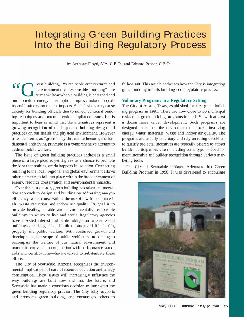
The City of Scottsdale, Arizona, recognizes the environ-mental implications of natural resource depletion and energyconsumption. These issues will increasingly influence theway buildings are built now and into the future, andScottsdale has made a conscious decision to jump-start thegreen building regulatory process. The City fully supportsand promotes green building, and encourages others to
follow suit. This article addresses how the City is integratinggreen building into its building code regulatory process.
Voluntary Programs in a Regulatory SettingThe City of Austin, Texas, established the first green build-ing program in 1991. There are now close to 20 municipalresidential green building programs in the U.S., with at leasta dozen more under development. Such programs aredesigned to reduce the environmental impacts involving energy, water, materials, waste and indoor air quality. Theprograms are usually voluntary and rely on rating checkliststo qualify projects. Incentives are typically offered to attractbuilder participation, often including some type of develop-ment incentive and builder recognition through various mar-keting tools.
The City of Scottsdale initiated Arizona’s first GreenBuilding Program in 1998. It was developed to encourage
Integrating Green Building Practices Into the Building Regulatory Process
by Anthony Floyd, AIA, C.B.O., and Edward Peaser, C.B.O.
May 2003 Building Safety Journal 35
36 Building Safety Journal May 2003
environmentally responsible building in the Sonoran Desertregion by incorporating healthy, resource- and energy-efficient materials and methods in the design and construc-tion of homes. The program’s goals are to reduce the environmental impact of building; achieve both short andlong-term savings of energy, water and other naturalresources; and encourage a healthier indoor environment.
Scottsdale’s program is strictly voluntary and uses incen-tives in the forms of builder recognition and expedited planreview to entice builder/developer participation. A consciouseffort has been made to promote the program to the con-struction and home-buying communities through publica-tions and public activities. Promotional materials includebrochures, building-strategy handouts, job site signs, a direc-tory of participating builders and designers, green buildinghome certificates, and a homeowner’s manual. A monthly lecture series is provided covering such topics as energy conservation, alternative materials, water conservation andindoor air quality. With the help of the City Green BuildingAdvisory Committee the program also hosts other events,including an Annual Green Building Expo and Home Tour.The City also has a green building website (www.scottsdaleaz.gov/greenbuilding) that contains program criteria,builder profiles, upcoming events and links to other environ-mental building resources.
To qualify, a project must meet a set number of prerequi-sites and score a minimum number of points from a ratingworksheet. The worksheet was developed by the City GreenBuilding Advisory Committee, which consists of representa-tives from the building community, utility companies, pro-duct manufacturers and Arizona State University. The work-sheet rates homes in the areas of site use, water and energyconsumption, building materials, solid waste production, andindoor air quality. The designer or builder can select from achecklist of green building options to achieve a rating ofeither “entry level” or “advanced level.”
By the end of 2002, 79 builders had submitted 183 projectsfor building permits under Scottsdale’s program. The proj-ects exhibited a wide range of construction strategies andmaterials, ranging from standard wood construction to hybridsystems, using innovative products such as insulated con-crete form systems, masonry walls with integral insulation,foam structural panels, pumice concrete, cast-earth, strawbale and super-insulated frame construction.
The decision to integrate green building into the planreview and inspection process was initiated as a result of limited staff resources. The green building program previously functioned with two staff members devoted exclu-
sively to green building. As the success of the program grew,it became increasingly difficult to keep up with project qual-ifications, inspections and outreach. When general buildingpermit activity slowed as the result of a generally sluggisheconomy, a window of opportunity opened to involve planreview and inspection in the green building process.Recognizing the growing interest of staff, the building offi-cial and inspection manager embraced the idea of integratinggreen building and making it a tool for learning about build-ing trends.
In fall of 2002, Scottsdale’s building plan review andinspection units began reviewing and inspecting projects forconformance to the City’s green building guidelines. The program is still voluntary, but requires that participatingbuilders adhere to program guidelines from start to finish.This protects the benefits and interests of both the home-owner and builder, while supporting the credibility and long-term goals of the program.
Integration into the Regulatory ProcessWhy integrate a non-regulatory program into a legislativeinfrastructure? First, the City of Scottsdale believes thatgreen building is a growing trend and wants to be preparedfor the inevitable. From our experience, we have noticed thatmany builders decide to participate in the green building pro-gram because they are already implementing many of itsenergy conservation strategies as a result of the competitivebuilding market. Because of the City’s program incentives,most of these builders are willing to go even further by incor-porating the additional criteria involving water conservation,the use of low-impact materials, waste reduction and indoorenvironmental quality.
Plan review and inspections are key. Without oversight,builders are not always consistent in their applications of theprogram criteria. Integrating green building into the planreview and inspection process also educates plan reviewersand inspectors on trends involving building strategies andalternate materials and methods of construction. It alsoserves to build the confidence of the citizens of Scottsdale inthe City’s concern for the long-term health and viability ofthe community.
Project Qualification and Plan ReviewOnce an owner or builder decides to participate in theScottsdale Green Building Program, a project qualificationmeeting is required prior to making a formal application forplan review permitting. Applicants complete a green buildingchecklist and enrollment form prior to the meeting. The
Integrating Green Building Practices Into the Building Regulatory Process
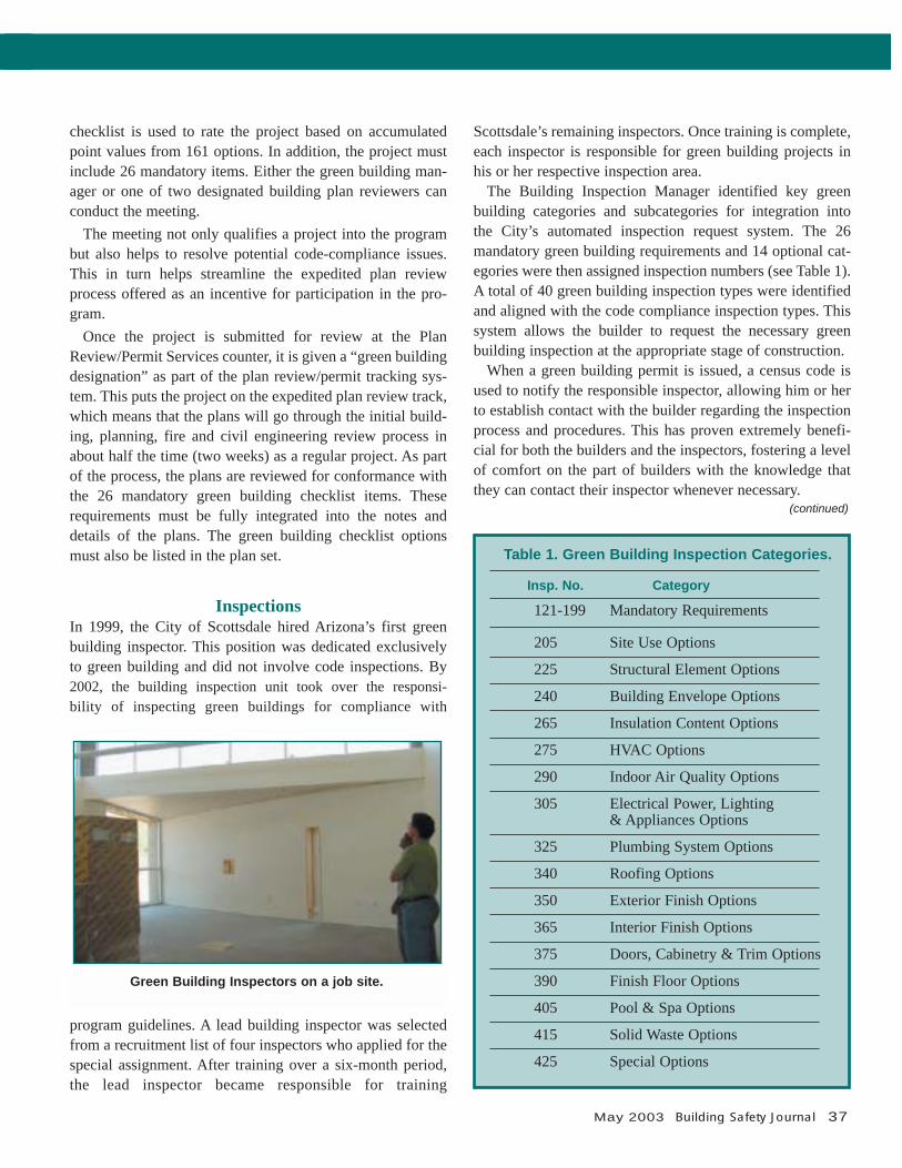
checklist is used to rate the project based on accumulatedpoint values from 161 options. In addition, the project mustinclude 26 mandatory items. Either the green building man-ager or one of two designated building plan reviewers canconduct the meeting.
The meeting not only qualifies a project into the programbut also helps to resolve potential code-compliance issues.This in turn helps streamline the expedited plan reviewprocess offered as an incentive for participation in the pro-gram.
Once the project is submitted for review at the PlanReview/Permit Services counter, it is given a “green buildingdesignation” as part of the plan review/permit tracking sys-tem. This puts the project on the expedited plan review track,which means that the plans will go through the initial build-ing, planning, fire and civil engineering review process inabout half the time (two weeks) as a regular project. As partof the process, the plans are reviewed for conformance withthe 26 mandatory green building checklist items. Theserequirements must be fully integrated into the notes anddetails of the plans. The green building checklist optionsmust also be listed in the plan set.
InspectionsIn 1999, the City of Scottsdale hired Arizona’s first greenbuilding inspector. This position was dedicated exclusivelyto green building and did not involve code inspections. By2002, the building inspection unit took over the responsi-bility of inspecting green buildings for compliance with
program guidelines. A lead building inspector was selectedfrom a recruitment list of four inspectors who applied for the special assignment. After training over a six-month period,the lead inspector became responsible for training
Scottsdale’s remaining inspectors. Once training is complete,each inspector is responsible for green building projects inhis or her respective inspection area.
The Building Inspection Manager identified key greenbuilding categories and subcategories for integration into the City’s automated inspection request system. The 26mandatory green building requirements and 14 optional cat-egories were then assigned inspection numbers (see Table 1).A total of 40 green building inspection types were identifiedand aligned with the code compliance inspection types. This system allows the builder to request the necessary greenbuilding inspection at the appropriate stage of construction.
When a green building permit is issued, a census code isused to notify the responsible inspector, allowing him or herto establish contact with the builder regarding the inspectionprocess and procedures. This has proven extremely benefi-cial for both the builders and the inspectors, fostering a levelof comfort on the part of builders with the knowledge thatthey can contact their inspector whenever necessary.
May 2003 Building Safety Journal 37
Table 1. Green Building Inspection Categories.
Insp. No. Category
121-199 Mandatory Requirements
205 Site Use Options
225 Structural Element Options
240 Building Envelope Options
265 Insulation Content Options
275 HVAC Options
290 Indoor Air Quality Options
305 Electrical Power, Lighting& Appliances Options
325 Plumbing System Options
340 Roofing Options
350 Exterior Finish Options
365 Interior Finish Options
375 Doors, Cabinetry & Trim Options
390 Finish Floor Options
405 Pool & Spa Options
415 Solid Waste Options
425 Special Options
Green Building Inspectors on a job site.
(continued)
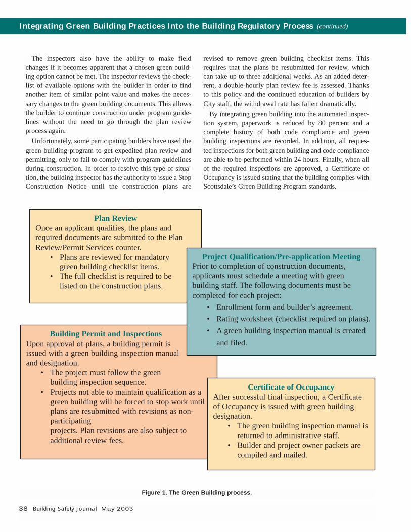
38 Building Safety Journal May 2003
The inspectors also have the ability to make fieldchanges if it becomes apparent that a chosen green build-ing option cannot be met. The inspector reviews the check-list of available options with the builder in order to findanother item of similar point value and makes the neces-sary changes to the green building documents. This allowsthe builder to continue construction under program guide-lines without the need to go through the plan reviewprocess again.
Unfortunately, some participating builders have used thegreen building program to get expedited plan review andpermitting, only to fail to comply with program guidelinesduring construction. In order to resolve this type of situa-tion, the building inspector has the authority to issue a StopConstruction Notice until the construction plans are
revised to remove green building checklist items. Thisrequires that the plans be resubmitted for review, whichcan take up to three additional weeks. As an added deter-rent, a double-hourly plan review fee is assessed. Thanksto this policy and the continued education of builders byCity staff, the withdrawal rate has fallen dramatically.
By integrating green building into the automated inspec-tion system, paperwork is reduced by 80 percent and a complete history of both code compliance and green building inspections are recorded. In addition, all reques-ted inspections for both green building and code complianceare able to be performed within 24 hours. Finally, when allof the required inspections are approved, a Certificate ofOccupancy is issued stating that the building complies withScottsdale’s Green Building Program standards.
Figure 1. The Green Building process.
Plan ReviewOnce an applicant qualifies, the plans andrequired documents are submitted to the PlanReview/Permit Services counter.
• Plans are reviewed for mandatorygreen building checklist items.
• The full checklist is required to belisted on the construction plans.
Building Permit and InspectionsUpon approval of plans, a building permit isissued with a green building inspection manualand designation.
• The project must follow the green building inspection sequence.
• Projects not able to maintain qualification as agreen building will be forced to stop work untilplans are resubmitted with revisions as non-participatingprojects. Plan revisions are also subject to additional review fees.
Project Qualification/Pre-application MeetingPrior to completion of construction documents, applicants must schedule a meeting with green building staff. The following documents must be completed for each project:
• Enrollment form and builder’s agreement. • Rating worksheet (checklist required on plans).• A green building inspection manual is created
and filed.
Integrating Green Building Practices Into the Building Regulatory Process (continued)
Certificate of OccupancyAfter successful final inspection, a Certificateof Occupancy is issued with green buildingdesignation.
• The green building inspection manual isreturned to administrative staff.
• Builder and project owner packets arecompiled and mailed.
May 2003 Building Safety Journal 39
To our knowledge, no other city in the U.S. has an auto-mated green building inspection request program with a fullstaff of building inspectors performing green building in-spections. Nor are we aware of any jurisdiction that issues aCertificate of Occupancy with a green building designation.
SummaryArizona does not currently have an energy code but as a“home rule” State, local jurisdictions maintain a significantamount of autonomy. Scottsdale attempted to adopt an energy code in the early 1990s, but was unsuccessful due to the political climate of the building industry at the time.Fortunately, the situation has improved and the City is nowpreparing for the adoption of the 2003 International EnergyConservation Code® (IECC®). Integrating the provisions ofthe IECC into the existing building code will result in man-dating most of the energy provisions that are now part of thevoluntary green building program. It is expected that this willcreate a greater synergy for the integration of other greenbuilding standards into the regulatory process.
As we continue the process of integration, we will facesome challenges. The first will be to maintain a proactive andopen-minded attitude toward alternate building practices.Meeting this challenge will require a thorough understandingof the intents of both the building code and specific greenbuilding guidelines in order to minimize conflicts. Having agreen building specialist on staff will certainly help in thisarea. The second challenge involves the prescriptive natureof the green building rating checklist. As with any checklist,the intended effect could be compromised if careful consid-eration is not given to how one component may affect another. For instance, selecting strategies for well-insulatedwalls in conjunction with low-performance windows willminimize overall energy performance. The adoption of en-ergy and performance-based codes can be of significant benefit, but a good understanding of the integrative approachis paramount.
Building departments are often reluctant to embraceunconventional materials and methods of construction.However, by undertaking a comprehensive view of the builtenvironment, proposed projects can be evaluated within thecontext of sustainability without sacrificing health- and life-safety standards. Fortunately, there is an ever-increasingnumber of sources for information regarding environmen-tally responsible building systems, materials and products.Green building programs around the country have certainlyhelped lay the foundation, and the next-generation buildingcodes are helping bridge the sustainability gap by taking a
life-cycle approach. Moving forward, we must also look toutilize historically proven solutions exhibited in indigenousbuilding systems around the world.
Building codes and standards are a critical part of the tech-nical framework by which the built environment takes itsform. Code agencies and standards bodies can help clarifythe scope of building regulation as sustainability becomes areality in the development process by improving provisionsfor health- and life-safety in the broader context of publicwelfare. The intent of specific code provisions and standardsmay vary, but they must ultimately be in alignment with prin-ciples that encompass a comprehensive and integrativeapproach in the design and construction of the built environ-ment. Today, this stands as perhaps the greatest challenge,and opportunity, for every building regulatory agency andjurisdiction in the U.S. and around the globe. ◆
AcknowledgmentsThe authors would like to thank the following individualswho have been vital to Scottsdale’s green building integra-tion process: Dave Potter, Building Official; Pedro Anzures,Building Inspector; Darrell Morrison, Plans Examiner;Michelle Dalton, Systems Integrator; and Sara Uribe, GreenBuilding Assistant.
Anthony Floyd, AIA, C.B.O., is a registered architect andformer building official for the City of Scottsdale. AsScottsdale’s Sustainable Building Manager, he oversees itsGreen Building Program and serves as resident authorityon sustainable building practices. Floyd is a past Presidentof the Arizona Chapter of ICBO and serves on the Board ofGovernors of the World Organization of Building Officials.
Edward Peaser, C.B.O., is a certified building official andhas served as Building Inspection Manager for the City ofScottsdale since 1997. He has worked for the City in several capacities since 1984, including as a buildinginspector and building inspector supervisor. Peaser is acertified building, electrical, mechanical, plumbing andcombination inspector. He is also an instructor of theInternational CodesTM at Scottsdale Community College.


![Software Pipelining and Superblock Scheduling: Compilation … · pipelining [6, 7] and superblock scheduling [8, 9, 10]. Software pipelining overlaps successive basic blocks from](https://static.documents.pub/doc/80x56/5f0469bd7e708231d40dd891/software-pipelining-and-superblock-scheduling-compilation-pipelining-6-7-and.jpg)


