175
Field Inspection of In-Service FRP Bridge Decks NATIONAL COOPERATIVE HIGHWAY RESEARCH PROGRAM NCHRP REPORT 564
| Date post: | 10-Apr-2018 |
| Category: |
Documents |
| Upload: | soniafaisal |
| View: | 223 times |
| Download: | 0 times |
8/8/2019 Inspection of FRP Decks
http://slidepdf.com/reader/full/inspection-of-frp-decks 1/175
Field Inspection of
In-Service FRP
Bridge Decks
NATIONAL
COOPERATIVE
HIGHWAY RESEARCH
PROGRAMNCHRPREPORT 564

8/8/2019 Inspection of FRP Decks
http://slidepdf.com/reader/full/inspection-of-frp-decks 2/175
TRANSPORTATION RESEARCH BOARD EXECUTIVE COMMITTEE 2006 (Membership as of April 2006)
OFFICERS
CHAIR: Michael D. Meyer, Professor, School of Civil and Environmental Engineering, Georgia Institute of Technology VICE CHAIR: Linda S. Watson, Executive Director, LYNX—Central Florida Regional Transportation Authority EXECUTIVE DIRECTOR: Robert E. Skinner, Jr., Transportation Research Board
MEMBERS
Michael W. Behrens, Executive Director, Texas DOT Allen D. Biehler, Secretary, Pennsylvania DOT John D. Bowe, Regional President, APL Americas, Oakland, CALarry L. Brown, Sr., Executive Director, Mississippi DOT Deborah H. Butler, Vice President, Customer Service, Norfolk Southern Corporation and Subsidiaries, Atlanta, GAAnne P. Canby, President, Surface Transportation Policy Project, Washington, DC Douglas G. Duncan, President and CEO, FedEx Freight, Memphis, TN Nicholas J. Garber, Henry L. Kinnier Professor, Department of Civil Engineering, University of Virginia, CharlottesvilleAngela Gittens, Vice President, Airport Business Services, HNTB Corporation, Miami, FLGenevieve Giuliano, Professor and Senior Associate Dean of Research and Technology, School of Policy, Planning,
and Development, and Director, METRANS National Center for Metropolitan Transportation Research, USC, Los AngelesSusan Hanson, Landry University Professor of Geography, Graduate School of Geography, Clark University James R. Hertwig, President, CSX Intermodal, Jacksonville, FLGloria J. Jeff, General Manager, City of Los Angeles DOT Adib K. Kanafani, Cahill Professor of Civil Engineering, University of California, Berkeley Harold E. Linnenkohl, Commissioner, Georgia DOT Sue McNeil, Professor, Department of Civil and Environmental Engineering, University of DelawareDebra L. Miller, Secretary, Kansas DOT Michael R. Morris, Director of Transportation, North Central Texas Council of GovernmentsCarol A. Murray, Commissioner, New Hampshire DOT John R. Njord, Executive Director, Utah DOT Sandra Rosenbloom, Professor of Planning, University of Arizona, TucsonHenry Gerard Schwartz, Jr., Senior Professor, Washington University Michael S. Townes, President and CEO, Hampton Roads Transit, Hampton, VAC. Michael Walton, Ernest H. Cockrell Centennial Chair in Engineering, University of Texas at Austin
Marion C. Blakey, Federal Aviation Administrator, U.S.DOT (ex officio)Joseph H. Boardman, Federal Railroad Administrator, U.S.DOT (ex officio)Rebecca M. Brewster, President and COO, American Transportation Research Institute, Smyrna, GA (ex officio)George Bugliarello, Chancellor, Polytechnic University of New York, and Foreign Secretary, National Academy of Engineering (ex officio)Sandra K. Bushue, Deputy Administrator, Federal Transit Administration, U.S.DOT (ex officio)J. Richard Capka, Acting Administrator, Federal Highway Administration, U.S.DOT (ex officio)
Thomas H. Collins (Adm., U.S. Coast Guard), Commandant, U.S. Coast Guard (ex officio)James J. Eberhardt, Chief Scientist, Office of FreedomCAR and Vehicle Technologies, U.S. Department of Energy (ex officio)Jacqueline Glassman, Deputy Administrator, National Highway Traffic Safety Administration, U.S.DOT (ex officio)Edward R. Hamberger, President and CEO, Association of American Railroads (ex officio)Warren E. Hoemann, Deputy Administrator, Federal Motor Carrier Safety Administration, U.S.DOT (ex officio)John C. Horsley, Executive Director, American Association of State Highway and Transportation Officials (ex officio)John E. Jamian, Acting Administrator, Maritime Administration, U.S.DOT (ex officio)J. Edward Johnson, Director, Applied Science Directorate, National Aeronautics and Space Administration (ex officio)Ashok G. Kaveeshwar, Research and Innovative Technology Administrator, U.S.DOT (ex officio)Brigham McCown, Deputy Administrator, Pipeline and Hazardous Materials Safety Administration, U.S.DOT (ex officio)William W. Millar, President, American Public Transportation Association (ex officio)Suzanne Rudzinski, Director, Transportation and Regional Programs, U.S. Environmental Protection Agency (ex officio)Jeffrey N. Shane, Under Secretary for Policy, U.S.DOT (ex officio)Carl A. Strock (Maj. Gen., U.S. Army), Chief of Engineers and Commanding General, U.S. Army Corps of Engineers (ex officio)
NATIONAL COOPERATIVE HIGHWAY RESEARCH PROGRAM
Transportation Research Board Executive Committee Subcommittee for NCHRP
Michael D. Meyer, Georgia Institute of Technology (Chair)J. Richard Capka, Federal Highway AdministrationJohn C. Horsley, American Association of State Highway and Transportation OfficialsJohn R. Njord, Utah DOT Robert E. Skinner, Jr., Transportation Research BoardC. Michael Walton, University of Texas at AustinLinda S. Watson, LYNX—Central Florida Regional Transportation Authority
8/8/2019 Inspection of FRP Decks
http://slidepdf.com/reader/full/inspection-of-frp-decks 3/175
TRANSPORTATION RESEARCH BOARD
WASHINGTON, D.C.
2006
www.TRB.org
N A T I O N A L C O O P E R A T I V E H I G H W A Y R E S E A R C H P R O G R A M
NCHRP REPORT 564
Research sponsored by the American Association of State Highway and Transportation Officials
in cooperation with the Federal Highway Administration
Subject Areas
Bridges, Other Structures, and Hydraulics and Hydrology
Field Inspection of
In-Service FRP
Bridge Decks
Niket M. Telang CONSTRUCTION TECHNOLOGY LABORATORIES, INC.
Skokie, IL
Chris DumlaoDUMLAO CONSULTING, INC.
Pleasanton, CA
Armin B. MehrabiBRIDGE ENGINEERING SOLUTIONS, INC.
Lewiston, NY
Adrian T. CiolkoCONSTRUCTION TECHNOLOGY LABORATORIES, INC.
Skokie, IL
Jim GutierrezCALIFORNIA MARITIME ACADEMY
Vallejo, CA

8/8/2019 Inspection of FRP Decks
http://slidepdf.com/reader/full/inspection-of-frp-decks 4/175
NATIONAL COOPERATIVE HIGHWAYRESEARCH PROGRAM
Systematic, well-designed research provides the most effective
approach to the solution of many problems facing highway
administrators and engineers. Often, highway problems are of local
interest and can best be studied by highway departments individually
or in cooperation with their state universities and others. However, the
accelerating growth of highway transportation develops increasingly
complex problems of wide interest to highway authorities. Theseproblems are best studied through a coordinated program of
cooperative research.
In recognition of these needs, the highway administrators of the
American Association of State Highway and Transportation Officials
initiated in 1962 an objective national highway research program
employing modern scientific techniques. This program is supported on
a continuing basis by funds from participating member states of the
Association and it receives the full cooperation and support of the
Federal Highway Administration, United States Department of
Transportation.
The Transportation Research Board of the National Academies was
requested by the Association to administer the research program
because of the Board’s recognized objectivity and understanding of
modern research practices. The Board is uniquely suited for this
purpose as it maintains an extensive committee structure from which
authorities on any highway transportation subject may be drawn; it
possesses avenues of communications and cooperation with federal,
state and local governmental agencies, universities, and industry; its
relationship to the National Research Council is an insurance of
objectivity; it maintains a full-time research correlation staff of
specialists in highway transportation matters to bring the findings of
research directly to those who are in a position to use them.
The program is developed on the basis of research needs identified
by chief administrators of the highway and transportation departments
and by committees of AASHTO. Each year, specific areas of research
needs to be included in the program are proposed to the National
Research Council and the Board by the American Association of State
Highway and Transportation Officials. Research projects to fulfill these
needs are defined by the Board, and qualified research agencies are
selected from those that have submitted proposals. Administration and
surveillance of research contracts are the responsibilities of the National
Research Council and the Transportation Research Board.
The needs for highway research are many, and the National
Cooperative Highway Research Program can make significant
contributions to the solution of highway transportation problems of
mutual concern to many responsible groups. The program, however, is
intended to complement rather than to substitute for or duplicate other
highway research programs.
Published reports of the
NATIONAL COOPERATIVE HIGHWAY RESEARCH PROGRAM
are available from:
Transportation Research BoardBusiness Office500 Fifth Street, NWWashington, DC 20001
and can be ordered through the Internet at:
http://www.national-academies.org/trb/bookstore
Printed in the United States of America
NCHRP REPORT 564
Price $42.00
Project 10-64
ISSN 0077-5614
ISBN: 0-309-09856-4
Library of Congress Control Number 2006927150
© 2006 Transportation Research Board
COPYRIGHT PERMISSION
Authors herein are responsible for the authenticity of their materials and for obtaining
written permissions from publishers or persons who own the copyright to any previously
published or copyrighted material used herein.
Cooperative Research Programs (CRP) grants permission to reproduce material in this
publication for classroom and not-for-profit purposes. Permission is given with the
understanding that none of the material will be used to imply TRB, AASHTO, FAA, FHWA,
FMCSA, FTA, or Transit Development Corporation endorsement of a particular product,
method, or practice. It is expected that those reproducing the material in this document for
educational and not-for-profit uses will give appropriate acknowledgment of the source of
any reprinted or reproduced material. For other uses of the material, request permission
from CRP.
NOTICE
The project that is the subject of this report was a part of the National Cooperative Highway
Research Program conducted by the Transportation Research Board with the approval of
the Governing Board of the National Research Council. Such approval reflects the
Governing Board’s judgment that the program concerned is of national importance and
appropriate with respect to both the purposes and resources of the National Research
Council.
The members of the technical committee selected to monitor this project and to review this
report were chosen for recognized scholarly competence and with due consideration for the
balance of disciplines appropriate to the project. The opinions and conclusions expressed
or implied are those of the research agency that performed the research, and, while they have
been accepted as appropriate by the technical committee, they are not necessarily those of
the Transportation Research Board, the National Research Council, the American
Association of State Highway and Transportation Officials, or the Federal Highway Administration, U.S. Department of Transportation.
Each report is reviewed and accepted for publication by the technical committee according
to procedures established and monitored by the Transportation Research Board Executive
Committee and the Governing Board of the National Research Council.
The Transportation Research Board of the National Academies, the National Research
Council, the Federal Highway Administration, the American Association of State Highway
and Transportation Officials, and the individual states participating in the National
Cooperative Highway Research Program do not endorse products or manufacturers. Trade
or manufacturers’ names appear herein solely because they are considered essential to the
object of this report.

8/8/2019 Inspection of FRP Decks
http://slidepdf.com/reader/full/inspection-of-frp-decks 5/175

8/8/2019 Inspection of FRP Decks
http://slidepdf.com/reader/full/inspection-of-frp-decks 6/175
CRP STAFF FOR NCHRP REPORT 564
Robert J. Reilly, Director, Cooperative Research Programs
Crawford F. Jencks, Manager, NCHRP
David B. Beal, Senior Program Officer
Eileen P. Delaney, Director of Publications
Andrea Briere, Editor
Beth Hatch, Editor
NCHRP PROJECT 10-64 PANELField of Materials and Construction—Area of Specifications,Procedures, and Practices
Paul V. Liles, Jr., Georgia DOT, Atlanta, GA (Chair)
Laura M. Amundson, Parsons Brinckerhoff, Minneapolis, MN
Rajinder P. Chawla, New Jersey DOT
Thomas J. Harrington, California DOT
Amir Mirmiran, Florida International University, Miami, FL
Guillermo Ramirez, University of Texas, Arlington
Steven M. Soltesz, Oregon DOT
Arthur P. Yannotti, New York State DOT
Eric P. Munley, FHWA Liaison
Frank N. Lisle, TRB Liaison
AUTHOR ACKNOWLEDGMENTS
The research presented in this report was performed under NCHRP Project 10-64 by Construction
Technology Laboratories, Inc. (CTL), along with sub-consultants Dumlao Consulting and Jim Gutierrez.
Niket M. Telang at CTL was the original principal investigator for this project; Adrian Ciolko of CTL
led the project through completion of outstanding tasks commencing in July 2004. Armin Mehrabi (for-
merly of CTL), Project Consultant from Bridge Engineering Solutions, Inc., and Chris Dumlao of Dum-
lao Consulting, Inc., were members of the research team.
C O O P E R A T I V E R E S E A R C H P R O G R A M S

8/8/2019 Inspection of FRP Decks
http://slidepdf.com/reader/full/inspection-of-frp-decks 7/175
This report contains a manual for the in-service inspection of fiber reinforced polymer(FRP) bridge decks. Documentation of the research leading to the development of theinspection manual is also included. The material in this report will be of immediate inter-est to FRP bridge inspectors, designers, and owners.
Inspection and monitoring of FRP structures varies widely, from no monitoring, tovisual inspection, to experimental nondestructive evaluation techniques. The criteria forfield inspection should be based on identification of critical components of FRP decks anddetermination of critical accumulated damage thresholds in those components. Otherinspection issues include accuracy and reliability requirements for inspection data, contin-uous versus periodic data collection, depth and frequency of inspection, reliability require-ments for equipment and sensors, and calibration of the guidelines with field project data.
In addition, the type of inspection data collected and the recording format vary. As aconsequence, it is difficult to compare one project with another. Thus, there is a need for astandard inspection reporting format to make such comparisons possible. Comparative
data would also help the composites industry to refine the technology to better meet thestates’ needs.The objective of this research was to develop recommended field procedures, evalua-
tion guidelines, and reporting standards for periodic inspection of in-service FRP bridgedecks. This material has been assembled into a detailed inspection manual covering allaspects of FRP deck inspection. A report documenting the research effort leading to thedevelopment of the manual is bound with the manual, and extensive appendices to thereport are available on the NCHRP website. An instructor’s guide, composed of a series of PowerPoint slides suitable for use in an in-house training program in the application of theinspection manual, is available from NCHRP.
This research was performed at the Construction Technology Laboratories, Inc., withthe assistance of Dumlao Consulting, Inc.; Bridge Engineering Solutions, Inc.; and Califor-
nia Maritime Academy.
F O R E W O R D
By David B. BealStaff Officer
Transportation Research Board
8/8/2019 Inspection of FRP Decks
http://slidepdf.com/reader/full/inspection-of-frp-decks 8/175
C O N T E N T S
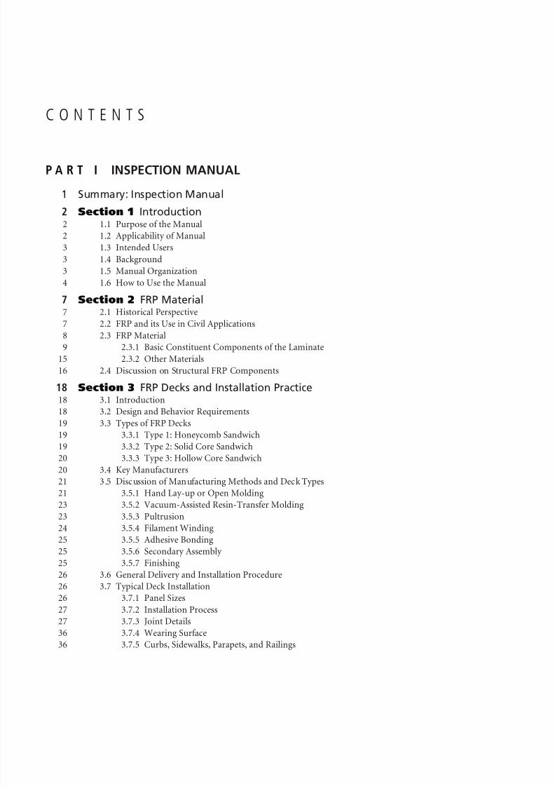
P A R T I INSPECTION MANUAL
1 Summary: Inspection Manual
2 Section 1 Introduction2 1.1 Purpose of the Manual
2 1.2 Applicability of Manual
3 1.3 Intended Users
3 1.4 Background
3 1.5 Manual Organization4 1.6 How to Use the Manual
7 Section 2 FRP Material7 2.1 Historical Perspective
7 2.2 FRP and its Use in Civil Applications
8 2.3 FRP Material
9 2.3.1 Basic Constituent Components of the Laminate
15 2.3.2 Other Materials
16 2.4 Discussion on Structural FRP Components
18 Section 3 FRP Decks and Installation Practice18 3.1 Introduction
18 3.2 Design and Behavior Requirements19 3.3 Types of FRP Decks
19 3.3.1 Type 1: Honeycomb Sandwich
19 3.3.2 Type 2: Solid Core Sandwich
20 3.3.3 Type 3: Hollow Core Sandwich
20 3.4 Key Manufacturers
21 3.5 Discussion of Manufacturing Methods and Deck Types
21 3.5.1 Hand Lay-up or Open Molding
23 3.5.2 Vacuum-Assisted Resin-Transfer Molding
23 3.5.3 Pultrusion
24 3.5.4 Filament Winding
25 3.5.5 Adhesive Bonding
25 3.5.6 Secondary Assembly 25 3.5.7 Finishing
26 3.6 General Delivery and Installation Procedure
26 3.7 Typical Deck Installation
26 3.7.1 Panel Sizes
27 3.7.2 Installation Process
27 3.7.3 Joint Details
36 3.7.4 Wearing Surface
36 3.7.5 Curbs, Sidewalks, Parapets, and Railings

8/8/2019 Inspection of FRP Decks
http://slidepdf.com/reader/full/inspection-of-frp-decks 9/175
39 Section 4 Significant Deck Details and Damage Types39 4.1 Overview
39 4.2 Deck External Details
39 4.2.1 Panel-to-Panel Connections
41 4.2.2 Deck-to-Girder Connections
44 4.2.3 Approach Joints
45 4.2.4 Wearing Surfaces45 4.2.5 Curbs, Sidewalks, Parapets, and Railings
46 4.3 Deck Panel Internal Details
46 4.3.1 Facesheets
47 4.3.2 Sandwich Cores
47 4.3.3 Edges and Closeouts
47 4.4 Visual Signs of Damage and Defects in FRP Material
48 4.4.1 Blistering
48 4.4.2 Voids
49 4.4.3 Discoloration
50 4.4.4 Wrinkling
50 4.4.5 Fiber Exposure
51 4.4.6 Cracks52 4.4.7 Scratches
53 Section 5 Inspection53 5.1 Types of Inspection
53 5.1.1 Visual Inspection
54 5.1.2 Tap Testing
55 5.1.3 Thermal Testing
57 5.1.4 Acoustic Testing
58 5.1.5 Ultrasonic Testing
59 5.1.6 Radiography
59 5.1.7 Modal Analysis
60 5.1.8 Load Testing62 5.1.9 Comparison of Methods
64 5.1.10 Inspector Qualifications, Site Safety, and Other Issues
64 5.2 Inspection of FRP Decks
65 5.2.1 Inspection of External Details
75 5.2.2 Inspection of Internal Details
81 5.3 Frequency and Depth of Inspection
82 Section 6 Recordkeeping82 6.1 Need for Standard Nomenclature for Parts, Locations, and Damages
82 6.2 Procedure for Recording Observations
83 6.3 Evaluation of Historic Data
84 6.4 Standard Checklists84 6.4.1 Pre-Inspection Checklist
85 6.4.2 Checklist of Details and Items to Be Inspected
85 6.4.3 FRP Damage Types Checklist
86 6.4.4 Inspection and Test Methods Checklist
86 6.5 Inspection Forms
91 Section 7 Condition Assessment91 7.1 Condition Rating of FRP Decks
92 7.1.1 Guidelines for Assessment and Condition Rating of FRP Decks

8/8/2019 Inspection of FRP Decks
http://slidepdf.com/reader/full/inspection-of-frp-decks 10/175
93 7.1.2 Condition Rating of the FRP Deck Structure
97 7.1.3 Condition Rating of Other Deck Features
100 7.2 Correlation of Damage to Likely Causes
101 7.2.1 Effects of Vehicular Loads
101 7.2.2 Effect of Punching Loads
102 7.2.3 Effect of Environmental and Other Loads
104 7.2.4 Other Effects105 7.3 Evaluation of Continued Existence of Causal Elements
105 7.4 Reference
106 Section 8 Case Study of the Salem Avenue Bridge
112 Glossary of Common Composites Industry Terms
119 Index
P A R T I I REPORT
124 Summary: Report
125 Chapter 1 Introduction and Research Approach125 1.1 Background
126 1.2 NCHRP Project Statement and Research Tasks
128 1.3 Research Approach
129 1.4 Research Tasks
133 1.5 Report Organization
135 Chapter 2 Findings135 2.1 Survey Findings
135 2.1.1 Types of FRP Decks in Service
137 2.1.2 Current Condition of FRP Deck Inventory
139 2.1.3 Current Inspection Practice
140 2.2 Findings from the Literature Survey 140 2.2.1 Historical Perspective on FRP Use
141 2.2.2 State of Research and Testing of FRP Decks
142 2.2.3 Inspection and Assessment of FRP Components
143 2.2.4 Damage Thresholds and Remaining Life Prediction
145 2.3 Key Publications
147 Chapter 3 Interpretation and Applications147 3.1 Issues with Design Variants
148 3.2 Issues with Current Inspection Practice
149 3.3 Classification of Significant Details
150 3.4 Inspection Methods, Their Applicability, Costs, and Other Issues
152 3.5 Details and Designs that Will Be Difficult to Inspect153 3.6 Inferring and Interpreting Inspection Results
155 Chapter 4 Conclusions
158 References for Report
163 Appendixes for Report

8/8/2019 Inspection of FRP Decks
http://slidepdf.com/reader/full/inspection-of-frp-decks 11/175
PART I:
INSPECTION MANUAL
8/8/2019 Inspection of FRP Decks
http://slidepdf.com/reader/full/inspection-of-frp-decks 12/175
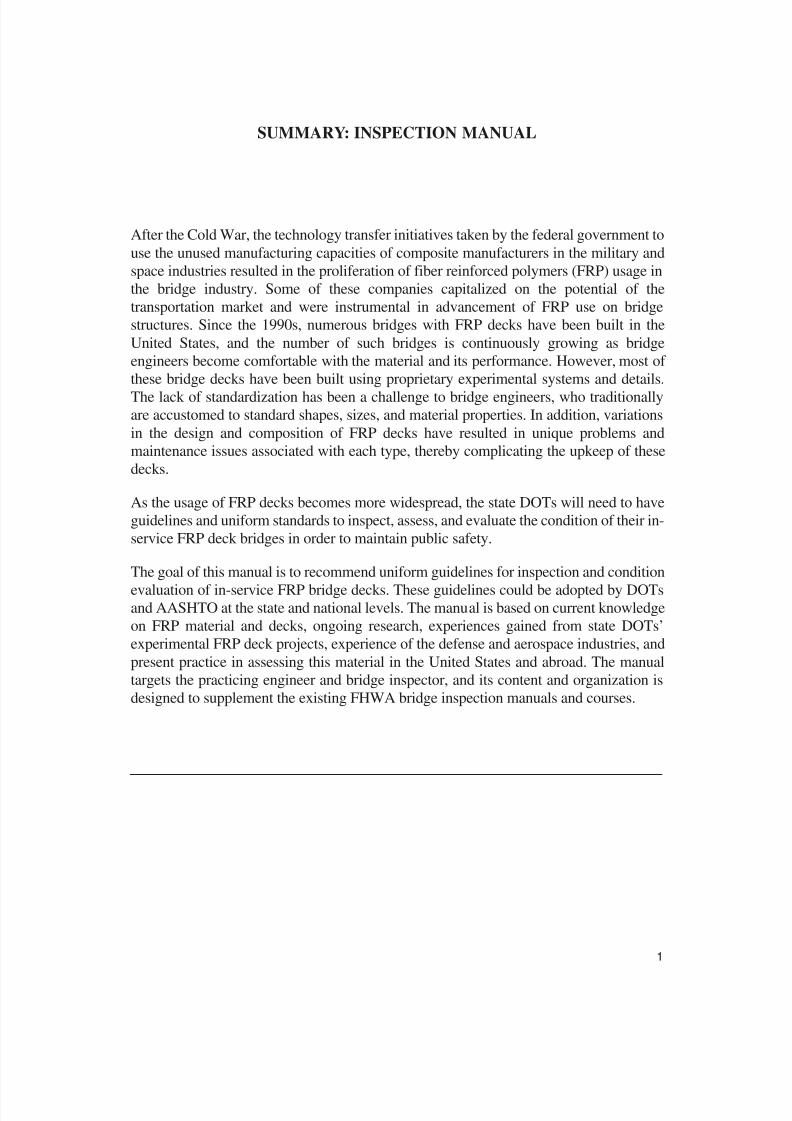
SUMMARY: INSPECTION MANUAL
After the Cold War, the technology transfer initiatives taken by the federal government touse the unused manufacturing capacities of composite manufacturers in the military andspace industries resulted in the proliferation of fiber reinforced polymers (FRP) usage inthe bridge industry. Some of these companies capitalized on the potential of thetransportation market and were instrumental in advancement of FRP use on bridgestructures. Since the 1990s, numerous bridges with FRP decks have been built in theUnited States, and the number of such bridges is continuously growing as bridgeengineers become comfortable with the material and its performance. However, most of these bridge decks have been built using proprietary experimental systems and details.
The lack of standardization has been a challenge to bridge engineers, who traditionallyare accustomed to standard shapes, sizes, and material properties. In addition, variationsin the design and composition of FRP decks have resulted in unique problems andmaintenance issues associated with each type, thereby complicating the upkeep of thesedecks.
As the usage of FRP decks becomes more widespread, the state DOTs will need to haveguidelines and uniform standards to inspect, assess, and evaluate the condition of their in-service FRP deck bridges in order to maintain public safety.
The goal of this manual is to recommend uniform guidelines for inspection and condition
evaluation of in-service FRP bridge decks. These guidelines could be adopted by DOTsand AASHTO at the state and national levels. The manual is based on current knowledgeon FRP material and decks, ongoing research, experiences gained from state DOTs’experimental FRP deck projects, experience of the defense and aerospace industries, andpresent practice in assessing this material in the United States and abroad. The manualtargets the practicing engineer and bridge inspector, and its content and organization isdesigned to supplement the existing FHWA bridge inspection manuals and courses.
1

8/8/2019 Inspection of FRP Decks
http://slidepdf.com/reader/full/inspection-of-frp-decks 13/175
SECTION 1: INTRODUCTION
1.1 PURPOSE OF THE MANUAL
This manual presents guidance for inspection and assessment of in-service fiber
reinforced polymer (FRP) bridge decks. Currently, there are no generally accepted
uniform standards or guidelines for field inspection of in-service FRP bridge decks. As
the use of FRP decks becomes more widespread, state DOTs will need uniform standards
to inspect and evaluate the condition of in-service FRP deck bridges. This manual
develops a uniform approach for inspection and evaluation of in-service FRP decks.
The manual is based on the findings of research sponsored by NCHRP. The objective of the NCHRP Project 10-64, Field Inspection of In-Service FRP Bridge Decks, is to
develop a manual and an inspector’s training course for field inspection of in-service FRPbridges. The research is based on current knowledge of FRP material and decks, ongoing
research, experiences from experimental FRP deck projects, experiences of the defense
and aerospace industries, and the present practice in the use and assessment of this
material in the United States and abroad. The manual and course target the practicing
engineer and bridge inspector, and their content and organization are designed to
supplement existing FHWA bridge inspection manuals and courses.
1.2 APPLICABILITY OF MANUAL
This manual is intended as a comprehensive document for use in field inspections of in-
service FRP decks. It is focused only on the inspection of FRP decks and, as such, doesnot address other aspects of bridge inspection covered in other publications by FHWAand AASHTO. Therefore, this manual shall be used in conjunction with other AASHTO,FHWA, and NCHRP references and manuals that cover complementary subjects of
bridge inspection.
These other complementary manuals and reference materials include, but are not limited
to, the latest editions of National Bridge Inspection Standards published by the federalgovernment; Standard Specifications for Highway Bridges and The Manual for
Condition Evaluation of Bridges published by AASHTO; The Safety Inspection of In-Service Bridges—Participant Notebook, Bridge Inspector’s Training Manual, and
Recording and Coding Guide for Structure Inventory and Appraisal of Nation’s Bridges
published by FHWA. In addition, specific codes and specifications published by stateDOTs or other local governing authorities shall also be used in conjunction with this
manual. Issues related to all bridges and bridge components other than FRP decks shallbe addressed in accordance with all existing codes and standards including thepublications listed above.
2
Field Inspection of In-Service FRP Bridge Decks: Inspection Manual
8/8/2019 Inspection of FRP Decks
http://slidepdf.com/reader/full/inspection-of-frp-decks 14/175

8/8/2019 Inspection of FRP Decks
http://slidepdf.com/reader/full/inspection-of-frp-decks 15/175
manual, and the manual organization. In addition, this section provides guidance on howbest to use this manual.
Section 2 – FRP Material: This section provides background on FRP material and itsuse in civil engineering, common material properties, standards and specificationscommonly used for design and manufacture of FRP material, and the philosophy of FRP
material design.
Section 3 – FRP Decks and Installation Practice: This section provides details onvarious types of FRP decks, comparative assessment of the various deck designs,installation practices, and FRP deck component details.
Section 4 – Significant Deck Details and Damage Types: This section discusses andillustrates the various details in FRP deck cross section, attached components, andinstallation details.
Section 5 – Inspection: This section presents guidelines on inspection of FRP decks—
with details on inspection locations, inspection methods, depth of inspection, andinspection frequency—along with a discussion on cost estimates and expertise requiredfor the various inspection methods.
Section 6 – Recordkeeping: This section provides guidelines for collection andrecordkeeping of FRP deck properties and inspection data. The section elaborates on thetype of data to be collected and recorded on the FRP deck material and cross section,deck condition, and notation of damage and deterioration. In addition, this sectionprovides guidance on a standard system for noting and describing deterioration anddamage.
Section 7 – Condition Assessment: This section provides guidance on correlating theobserved damage or deterioration to severity levels and condition ratings. In addition, thissection presents discussion on causal elements, likelihood of damage progression, andpotential likelihood of failure.
Section 8 – Case Study: This section provides an FRP deck inspection case study of theSalem Avenue Bridge in Dayton, Ohio.
1.6 HOW TO USE THE MANUAL
This manual is intended for use by bridge owners as a guideline and training resource forinspecting, assessing, and documenting condition of these new bridge elements.
Because FRP design, fabrication, construction, and behavior are unusual, inspectors andinspector trainees are urged to familiarize themselves with the first four sections. Thesesections serve as the foundation for effective inspection. Because specific nomenclatureis used for FRP components, inspectors should refer frequently to the glossary providedin the manual to avoid future inspection documentation errors.
Field Inspection of In-Service FRP Bridge Decks: Inspection Manual
4

8/8/2019 Inspection of FRP Decks
http://slidepdf.com/reader/full/inspection-of-frp-decks 16/175
5
Field Inspection of In-Service FRP Bridge Decks: Inspection Manual
This section introduces the manual and provides guidance in using the manual forinspection purposes. Section 2 of the manual introduces both seasoned inspectors andinspector trainees to FRP material and its general construction uses.
Section 3 provides detailed information on FRP bridge deck designs, illustrated withdrawings and details of the various FRP deck systems in use today on bridges in the
United States. This section defines types of FRP decks, lists key manufacturers, describestypical details and installation practices, and provides a general discussion of thedetailing philosophy. Unlike the traditional deck construction materials and systems thathave been in use for close to a century, new FRP materials and systems have proliferatedrapidly in only the last 10 years. Many of the deck fabricators and developersare manufacturers with core business activities unrelated to bridge construction.Therefore, inspectors need to familiarize themselves with the features of FRP bridgedecks and their connections and with unique details of deck components such as theparapets, curbs, and wearing surfaces. To conduct accurate inspections and conditionratings, inspectors must also become familiar with presently known defects andsymptoms of deterioration in FRP decks. These are identified in detail in Section 4.
Primary guidance on inspection techniques and their documentation for FRP decks isoffered in Sections 5 and 6, including details of various inspection methods and theiradaptation in inspecting FRP decks. Inspectors also receive guidance and references tospecialized test methods beyond the scope of conventional inspection protocols; thesespecialized methods are to be used when unexplained or unexpected damage to FRPdecks is discovered or suspected. Inspectors must become familiar with the guidanceprovided on recording and filing inspection data. Checklists of items are offered, alongwith the type of data to be collected for the various kinds of decks.
Section 7 discusses the assessment and rating of deck conditions and provides guidance
on correlating inspection observations to the severity of the damage and rating of thedeck condition. This section is of greatest interest to the engineer or inspector chargedwith assessing and evaluating the condition of the FRP bridge decks based on observedfield conditions.
Inspectors are urged to review a case study providing an example of typical FRP deck inspection in Section 8. Guidance on terminology is provided in the Glossary. An indexof topics concludes the manual.
For the convenience of the reader, the following quick-reference table provides guidanceto this manual at a glance.

8/8/2019 Inspection of FRP Decks
http://slidepdf.com/reader/full/inspection-of-frp-decks 17/175
Field Inspection of In-Service FRP Bridge Decks: Inspection Manual
6
HOW TO USE THIS INSPECTION MANUAL
LOOKING FOR...? GO TO MANUAL
SECTION
If you are already familiar with FRP material and deck types, manufacturers, and processes
Section 4
To familiarize yourself with FRP material Section 2
To familiarize yourself with FRP deck types, details and
construction Section 3
To familiarize yourself with fabrication and
construction details and componentsSection 4
To familiarize yourself with common terminology Glossary
To learn what inspection methods are available, theircosts, and the scope of their application
Section 5
To learn how to record and file and to review a list of things to inspect
Section 6
To learn how to use the inspection results to rate the
condition of the deck Section 7

8/8/2019 Inspection of FRP Decks
http://slidepdf.com/reader/full/inspection-of-frp-decks 18/175
SECTION 2: FRP MATERIAL
2.1 HISTORICAL PERSPECTIVE
FRP composite materials consist of two or more distinct constituent materials with
recognizable interfaces between them. The constituent materials are intentionally
combined to “engineer” a desired set of properties in the composite material so that it
can perform its functions optimally.
Composite materials have existed for centuries—for example, ancient Egyptian culture
improved the strength of building bricks by using straw as reinforcement in clay.
Similarly, reinforced concrete can be considered a composite material. However, thefocus of this manual will be specifically on polymeric resin-based composites.
Polymer-based composites were not widely used until after World War II, when
fiberglass reinforcements and thermosetting resins such as polyesters became
commercially available and affordable. In the 1950s and 1960s, much of the development
in composite structures took place in the aerospace and automotive industries where
composites’ high stiffness-to-weight ratio and corrosion resistance were immediately
beneficial despite the higher cost per pound for finished goods. As new manufacturing
techniques were developed, the cost for composite goods dropped, and demand spilled
into other industries such as boating, sporting goods, tanks, and pressure vessels. In the
last 20 years, a construction component manufacturing industry has emerged with several
commercial companies offering FRP composite deck systems as drop-in replacements
for steel or concrete deck systems.
2.2 FRP AND ITS USE IN CIVIL APPLICATIONS
The large-scale use of FRP composites in civil applications has occurred mostly within
the last 15 years. A 1995 report by the Great Lakes Composites Consortium and
BIRL/Northwestern University identified areas in which FRP composites could play key
roles in rebuilding and maintaining civil infrastructure because of the composites’
corrosion resistance and high strength. The report data were gathered by asking
transportation agencies and civil engineering professionals to define requirements thatcould be addressed with composites. The report identified four areas that FRP
composites would improve: (1) corrosion mitigation, (2) reinforcement of degraded
bridge components, (3) seismic protection, and (4) low-cost erection/maintenance.
Recent papers discuss FHWA research programs specifically related to FRP applicationsin bridge construction, strengthening, or repair and describe the ensuing growth of FRPmaterials in civil applications. In a section on new bridge construction, these publicationssuccinctly describe some of the bridge systems developed and installed in 44 Innovative
7
Field Inspection of In-Service FRP Bridge Decks: Inspection Manual
8/8/2019 Inspection of FRP Decks
http://slidepdf.com/reader/full/inspection-of-frp-decks 19/175
Bridge Research Program projects as of 2003. These are in addition to installations underseparate federal agency programs such as DARPA (Department of Defense AdvancedResearch Projects Agency) and various state DOT–sponsored programs.
2.3 FRP MATERIAL
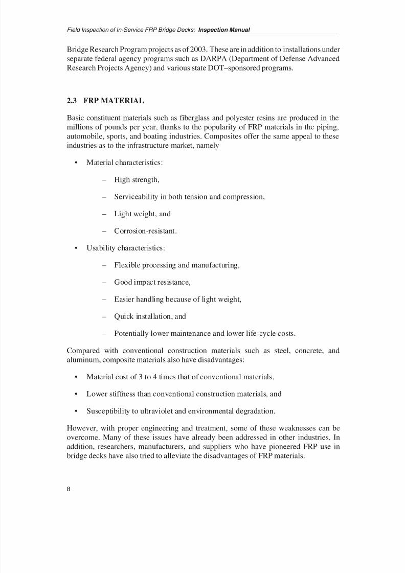
Basic constituent materials such as fiberglass and polyester resins are produced in themillions of pounds per year, thanks to the popularity of FRP materials in the piping,automobile, sports, and boating industries. Composites offer the same appeal to theseindustries as to the infrastructure market, namely
• Material characteristics:
– High strength,
– Serviceability in both tension and compression,
– Light weight, and
– Corrosion-resistant.
• Usability characteristics:
– Flexible processing and manufacturing,
– Good impact resistance,
– Easier handling because of light weight,
– Quick installation, and
– Potentially lower maintenance and lower life-cycle costs.
Compared with conventional construction materials such as steel, concrete, andaluminum, composite materials also have disadvantages:
• Material cost of 3 to 4 times that of conventional materials,
• Lower stiffness than conventional construction materials, and
• Susceptibility to ultraviolet and environmental degradation.
However, with proper engineering and treatment, some of these weaknesses can beovercome. Many of these issues have already been addressed in other industries. Inaddition, researchers, manufacturers, and suppliers who have pioneered FRP use inbridge decks have also tried to alleviate the disadvantages of FRP materials.
Field Inspection of In-Service FRP Bridge Decks: Inspection Manual
8
8/8/2019 Inspection of FRP Decks
http://slidepdf.com/reader/full/inspection-of-frp-decks 20/175
9
Field Inspection of In-Service FRP Bridge Decks: Inspection Manual
2.3.1 BASIC CONSTITUENT COMPONENTS OF THE LAMINATE
At the macro level, FRP composite materials are composed of two primary components:a polymer matrix resin and fiber reinforcements. Additives and fillers that enhanceparticular characteristics of the system are a third component. However, the resin andfiber reinforcements drive the material-dependent characteristics of the deck. With few
exceptions, composites are built up of stacked layers, or laminates, of FRP material.Hence, the finished material is commonly referred to as a composite laminate.
2.3.1.1 Matrix Resin
The matrix is the component that creates volume and supports the fiber reinforcement.All current bridge-deck systems employ thermosetting polymers as the matrix.Thermosetting polymers are a class of polymers that are worked in a liquid state and thenchemically reacted to form a cured, solid state. It is this two-phase characteristic thatenables the consolidation of fiber reinforcement into the matrix during manufacturing.Other matrix materials include thermoplastic resins and ceramic-type materials, but these
matrix materials are not being used currently in deck manufacturing; therefore, thisdiscussion is limited to thermosetting resins.
The most popular thermosetting resins being used in industry are described below.
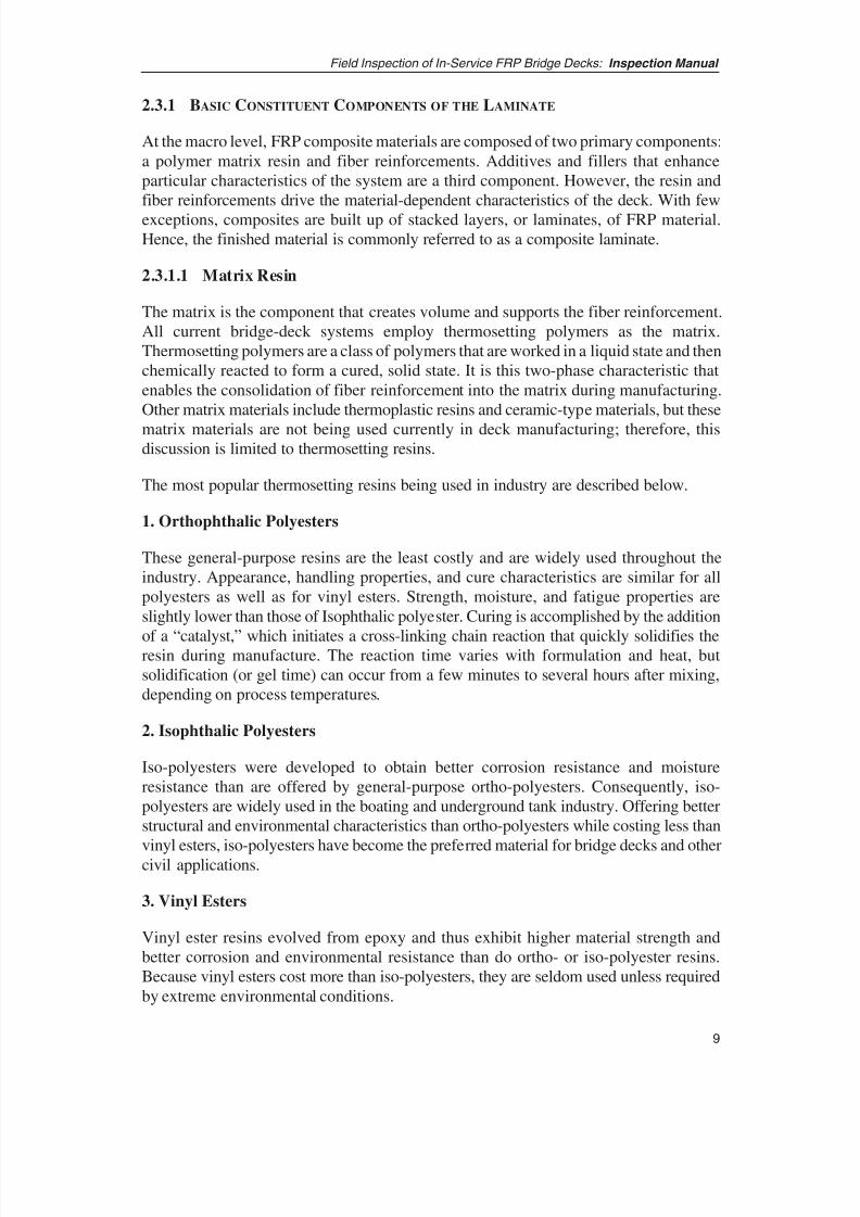
1. Orthophthalic Polyesters
These general-purpose resins are the least costly and are widely used throughout theindustry. Appearance, handling properties, and cure characteristics are similar for allpolyesters as well as for vinyl esters. Strength, moisture, and fatigue properties areslightly lower than those of Isophthalic polyester. Curing is accomplished by the addition
of a “catalyst,” which initiates a cross-linking chain reaction that quickly solidifies theresin during manufacture. The reaction time varies with formulation and heat, butsolidification (or gel time) can occur from a few minutes to several hours after mixing,depending on process temperatures.
2. Isophthalic Polyesters
Iso-polyesters were developed to obtain better corrosion resistance and moistureresistance than are offered by general-purpose ortho-polyesters. Consequently, iso-polyesters are widely used in the boating and underground tank industry. Offering betterstructural and environmental characteristics than ortho-polyesters while costing less than
vinyl esters, iso-polyesters have become the preferred material for bridge decks and othercivil applications.
3. Vinyl Esters
Vinyl ester resins evolved from epoxy and thus exhibit higher material strength andbetter corrosion and environmental resistance than do ortho- or iso-polyester resins.Because vinyl esters cost more than iso-polyesters, they are seldom used unless requiredby extreme environmental conditions.

8/8/2019 Inspection of FRP Decks
http://slidepdf.com/reader/full/inspection-of-frp-decks 21/175
4. Epoxies
Epoxies differ chemically from polyester resins and cure through a different reactionprocess. Epoxies can be formulated with an infinite variety of chemical structures; thus,the physical properties can be tuned to enhance specific material traits. Epoxy systemstypically consist of two parts—the resin and a hardener—which are mixed, then allowed
to cure. Physical properties of epoxies are highly dependent on curing temperature andare better for elevated temperature systems versus room temperature cure.
Epoxies are considerably more expensive than the polyesters or vinyl esters, so epoxiesare generally used where peak performance is required, as in the aerospace industry. Nomanufacturers currently use epoxy resins for their bridge deck system.
Table 2.3.1.1-1 lists the mechanical properties of the polyester matrix resins without andwith fiber reinforcements (fiberglass mat type). As seen in the table, the strength andstiffness of the composite material comes mainly from the fiber reinforcements. Onemust keep in mind that the resin serves to protect the fibers and provides a mechanism for
load transfer between fibers. The heat deflection temperature (HDT) is the temperature atwhich the resin will “soften” and lose strength. Note the higher HDT temperature of vinylester over the polyesters.
Field Inspection of In-Service FRP Bridge Decks: Inspection Manual
10
Resin SystemCompressive
Strengthk si
Tensile
Strengthk si
Tensile
ModulusMsi
HeatDeflection
Temp°F
Withoutreinforcement 2 NA 7.2–8.5
0.45–0.66
Orthophthalic With fiberglassreinforcement 3
NA 22 1.7 175
Withoutreinforcement 2 17 10–11.7 0.45–0.65
IsophthalicWith fiberglassreinforcement 3
30 23 1.7
195
Withoutreinforcement 2 NA 11–12.7 0.46–0.57
Vinyl esterWith fiberglassreinforcement 3
30 23 1.6
212
Withoutreinforcement 4 NA 7–8 0.43–0.55
EpoxyWith fiberglass
reinforcement3,4
35 30 1.8120–2205
1Hancox and Mayer, Design Dat a for Rein forced Plastics, Chapman and Hall, London,
UK, 1994.2Typical range after f ull cure, dry. Not normally used in structure without reinforcement.3Based on fiberglass mat reinforcement at 40% fiber volume.4Room temperature cure epoxy systems, heated systems will be slightly higher.5Low value is for room temperature cure, high value for heated process.
Table 2.3.1.1–1 Typical Mechanical Properties of Common Resins 1
8/8/2019 Inspection of FRP Decks
http://slidepdf.com/reader/full/inspection-of-frp-decks 22/175
11
Field Inspection of In-Service FRP Bridge Decks: Inspection Manual
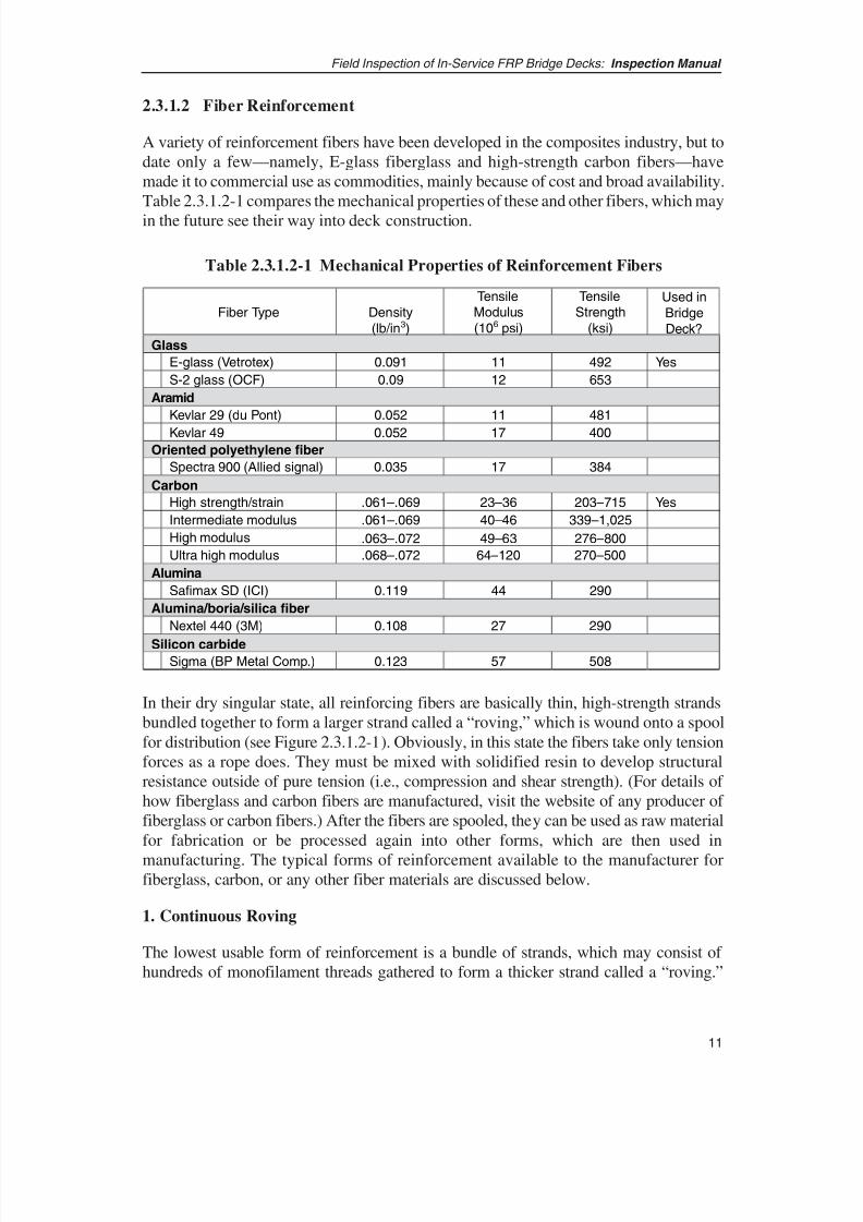
2.3.1.2 Fiber Reinforcement
A variety of reinforcement fibers have been developed in the composites industry, but todate only a few—namely, E-glass fiberglass and high-strength carbon fibers—havemade it to commercial use as commodities, mainly because of cost and broad availability.Table 2.3.1.2-1 compares the mechanical properties of these and other fibers, which may
in the future see their way into deck construction.
Fiber Type Density
(lb/in3)
TensileModulus
(106 psi)
TensileStrength
(ksi)
Used in
Bridge
Deck?
Glass
E-glass (Vetrotex) 0.091 11 492 Yes
S-2 glass (OCF) 0.09 12 653
Aramid
Kevlar 29 (du Pont) 0.052 11 481
Kevlar 49 0.052 17 400
Oriented polyethylene fiber
Spectra 900 (Allied signal) 0.035 17 384
Carbon
High strength/ strain .061–.069 23–36 203–715 Yes
Intermediate modulus .061–.069 40–46 339–1,025
High modulus .063–.072 49–63 276–800
Ultra high modulus .068–.072 64–120 270–500
Alumina
Safimax SD (ICI) 0.119 44 290
Alumina/boria/ silica fiber
Nextel 440 (3M) 0.108 27 290
Silicon carbideSigma (BP Metal Comp.) 0.123 57 508
Table 2.3.1.2-1 Mechanical Properties of Reinforcement Fibers
In their dry singular state, all reinforcing fibers are basically thin, high-strength strandsbundled together to form a larger strand called a “roving,” which is wound onto a spoolfor distribution (see Figure 2.3.1.2-1). Obviously, in this state the fibers take only tensionforces as a rope does. They must be mixed with solidified resin to develop structuralresistance outside of pure tension (i.e., compression and shear strength). (For details of how fiberglass and carbon fibers are manufactured, visit the website of any producer of fiberglass or carbon fibers.) After the fibers are spooled, they can be used as raw materialfor fabrication or be processed again into other forms, which are then used in
manufacturing. The typical forms of reinforcement available to the manufacturer forfiberglass, carbon, or any other fiber materials are discussed below.
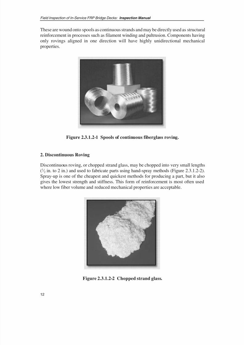
1. Continuous Roving
The lowest usable form of reinforcement is a bundle of strands, which may consist of hundreds of monofilament threads gathered to form a thicker strand called a “roving.”
8/8/2019 Inspection of FRP Decks
http://slidepdf.com/reader/full/inspection-of-frp-decks 23/175
These are wound onto spools as continuous strands and may be directly used as structuralreinforcement in processes such as filament winding and pultrusion. Components havingonly rovings aligned in one direction will have highly unidirectional mechanicalproperties.
Field Inspection of In-Service FRP Bridge Decks: Inspection Manual
12
Figure 2.3.1.2-1 Spools of continuous fiberglass roving.
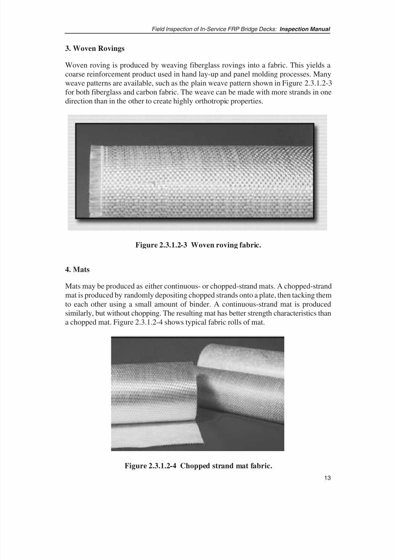
Figure 2.3.1.2-2 Chopped strand glass.
2. Discontinuous Roving
Discontinuous roving, or chopped strand glass, may be chopped into very small lengths(1 ⁄ 2 in. to 2 in.) and used to fabricate parts using hand-spray methods (Figure 2.3.1.2-2).Spray-up is one of the cheapest and quickest methods for producing a part, but it also
gives the lowest strength and stiffness. This form of reinforcement is most often usedwhere low fiber volume and reduced mechanical properties are acceptable.
8/8/2019 Inspection of FRP Decks
http://slidepdf.com/reader/full/inspection-of-frp-decks 24/175
13
Field Inspection of In-Service FRP Bridge Decks: Inspection Manual
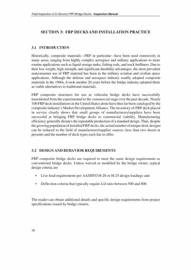
3. Woven Rovings
Woven roving is produced by weaving fiberglass rovings into a fabric. This yields acoarse reinforcement product used in hand lay-up and panel molding processes. Manyweave patterns are available, such as the plain weave pattern shown in Figure 2.3.1.2-3for both fiberglass and carbon fabric. The weave can be made with more strands in one
direction than in the other to create highly orthotropic properties.
Figure 2.3.1.2-3 Woven roving fabric.
Figure 2.3.1.2-4 Chopped strand mat fabric.
4. Mats
Mats may be produced as either continuous- or chopped-strand mats. A chopped-strand
mat is produced by randomly depositing chopped strands onto a plate, then tacking themto each other using a small amount of binder. A continuous-strand mat is producedsimilarly, but without chopping. The resulting mat has better strength characteristics thana chopped mat. Figure 2.3.1.2-4 shows typical fabric rolls of mat.

8/8/2019 Inspection of FRP Decks
http://slidepdf.com/reader/full/inspection-of-frp-decks 25/175
5. Non-crimp Fabric
By stitching or knitting the reinforcement strands together using lightweight threads,sheets of fabric can be made without weaving to produce straight, non-crimped, layers of fibers (see Figure 2.3.1.2-5). This form of sheet reinforcement has become popular fordeck fabrication because it allows large quantities of fiber reinforcement on single spools.
Moreover, unlike woven fabric, the non-crimped fiber strands maintain their straightnessand, hence, have higher stiffness and strength retention. Non-crimped fabrics aremanufactured in multiple layers, so in essence they themselves are sub-laminates. On theother hand, however, non-crimp fabric costs more to manufacture than other forms.
Field Inspection of In-Service FRP Bridge Decks: Inspection Manual
14
Figure 2.3.1.2-5 Non-crimp fabric construction.
2.3.1.3 Fillers
Fillers can be added to the matrix resin to alter, enhance, or control the materialcharacteristics of the ensuing laminate. Manufacturers generally have a list and quantityof these fillers available for their products and, if needed, information on specific fillersused on a project can be obtained from the manufacturer. Table 2.3.1.3-1 lists sometypical fillers and their function.
Filler Function
Aluminum trihydrate Shrink reduction, flame retardancy,
CTE reductionCalcium carbonate Resin thickener, UV stabilizerClay Resin flow
Silica ThixotropyGlass spheres Density reduction
Table 2.3.1.3-1 - Typical Filler Materials

8/8/2019 Inspection of FRP Decks
http://slidepdf.com/reader/full/inspection-of-frp-decks 26/175
15
Field Inspection of In-Service FRP Bridge Decks: Inspection Manual
2.3.2 OTHER MATERIALS
In addition to the constituent materials, other materials may be introduced into the FRPmaterial or added to the composite laminate as enhancements to improve specificproperties of the FRP material. A short list and basic description of these components aregiven in the following sections.
2.3.2.1 Adhesives
Adhesives are materials that join various substrates and laminates (also known as“adherends”) together. The total assembly of adhesive and adherends are known as joints.One of the major advantages of using adhesives is that it eliminates the drilling of holesor other mechanical methods for joining structural substrates. Examples of different typesof adhesives include glue, hot-melt adhesives, pressure sensitive adhesives, filmadhesives, and structural adhesives. These can be processed using various techniquesincluding thermal, electron beam, ultraviolet (UV), and microwave curing. When usingadhesives, cleanliness of substrates, silane coupling agents, and matching coefficients of
thermal expansion (CTE) are all-important parameters for bond quality. Specialists withknowledge and experience in adhesive technology select appropriate adhesives based onthe properties of the adherends as well as the likely environmental conditions to beexperienced by the FRP component.
2.3.2.2 Foam Cores
In some processes, such as in resin transfer molding, lightweight solid materials mayneed to be included in order to eliminate cavities and prevent resin pooling. Typical“core” materials are listed below in Table 2.3.2.2-1. Note that the type used by deck manufacturers may not be restricted to those mentioned.
These materials are also used to build the core section of sandwich type panels in somedeck designs. Because all deck suppliers specify core material according to their designspecifications, the list of materials is presented for reference only and provides a feel forthe weight and expected sensitivity to water absorption of the material. Actual propertiesand environmental specifications must be obtained from the deck manufacturer.
Material
Density
(lb/ft3
)
Water Absorption
(% estimate)
Relative
CostPolyurethane foam 5 – 30 .2 Medium
Urea-formaldehyde foam 2 – 25 20 Low
PVC foam 5 – 30 15 Low
Balsa wood 2 –10 Significant Low
Honeycomb 1 – 10 Low High
Table 2.3.2.2-1 Selected Light Weight Foam Cores

8/8/2019 Inspection of FRP Decks
http://slidepdf.com/reader/full/inspection-of-frp-decks 27/175
Field Inspection of In-Service FRP Bridge Decks: Inspection Manual
16
2.3.2.3 Gelcoat
Gelcoat is a thick resin overcoat applied to finished FRP components to improve eithersurface properties or surface finish, or both. The coating can be of a different resin thanthe matrix resin, one that is filled with UV inhibitors or fillers to improve surfacetoughness and weathering characteristics. Gelcoats are generally applied only to
environmentally exposed surfaces such as at the sides or the bottom of the deck and notto the overlaid surface. The gelcoat is typically pigmented and is thus opaque, so it maymask laminate damages or blemishes that might be visible during manufacturing.Gelcoats can enhance the durability of the FRP composite by serving as a surface barrieragainst UV deterioration, flammability, and moisture pickup.
2.4 DISCUSSION ON STRUCTURAL FRP COMPONENTS
By combining the material constituents described above, designers can tailor their FRP
composite. With the exception of rods and long narrow members, most FRP compositesare composed of layers of fabric made with combinations of woven roving, mat, and non-crimp fabric saturated with resin then cured to obtain a solid structural laminate. Thislaminate, in turn, can be bonded to additional laminates to form the final structuralmember. This is best illustrated by the detailed lay-up specifications for the SchuylerHeim Bridge (Long Beach, CA) shown in Figures 2.4-1 and 2.4-2. The lay-up schedulecontains more information than the reader requires to become familiar with FRP deck inspection, but the main idea of this illustration is to show the multitude of layers of FRPmaterials that define the overall cross section, including fiberglass fabric reinforcements(EQX), carbon reinforcements (C-LR), mat fabric (MAT), and secondary componentssuch as a foam core and pre-made FRP pultruded tubes.
This particular deck shown in Figure 2.4-1 is a sandwich construction, so laminates areassociated with particular sections of the deck as labeled in Figure 2.4-2. In general, mostdecks manufactured with FRP composites follow the same prescription for sandwichconstruction: namely, a lightweight core with load-carrying top and bottom facesheets.Information on other deck designs and fabrication techniques is included in Section 3.

8/8/2019 Inspection of FRP Decks
http://slidepdf.com/reader/full/inspection-of-frp-decks 28/175
17
Field Inspection of In-Service FRP Bridge Decks: Inspection Manual
Figure 2.4-1 34-ft. x 6-ft. FRP composite deck for the Schuyler Heim Bridge.
Figure 2.4-2 Laminate details for the Schuyler Heim Bridge deck.
8/8/2019 Inspection of FRP Decks
http://slidepdf.com/reader/full/inspection-of-frp-decks 29/175
SECTION 3: FRP DECKS AND INSTALLATION PRACTICE
3.1 INTRODUCTION
Historically, composite materials—FRP in particular—have been used extensively in
many areas, ranging from highly complex aerospace and military applications to more
routine applications such as liquid storage tanks, fishing rods, and truck bedliners. Due to
their low weight, high strength, and significant durability advantages, the most prevalent
nonconsumer use of FRP material has been in the military aviation and civilian space
applications. Although the defense and aerospace industry readily adopted composite
materials in the 1960s, it took another 20 years before the bridge industry adopted them
as viable alternatives to traditional materials.
FRP composite structures for use as vehicular bridge decks have successfullytransitioned from the experimental to the commercial stage over the past decade. Nearly
100 FRP deck installations in the United States alone have thus far been cataloged by the
composite industry’s Market Development Alliance. The inventory of FRP deck placed
in service clearly shows that small groups of manufacturers/suppliers have been
successful at bringing FRP bridge decks to commercial viability. Manufacturing
efficiency generally dictates the repeatable production of a standard design. Thus, despite
the growing population of installed FRP decks, the actual number of unique deck designs
can be reduced to the field of manufacturer/supplier sources (less than two dozen at
present) and the number of deck types each has to offer.
3.2 DESIGN AND BEHAVIOR REQUIREMENTS
FRP composite bridge decks are required to meet the same design requirements as
conventional bridge decks. Unless waived or modified by the bridge owner, typical
design criteria are
• Live-load requirements per AASHTO H-20 or H-25 design loadings and
• Deflection criteria that typically require L/d ratio between 500 and 800.
The reader can obtain additional details and specific design requirements from project
specifications issued by bridge owners.
18
Field Inspection of In-Service FRP Bridge Decks: Inspection Manual
8/8/2019 Inspection of FRP Decks
http://slidepdf.com/reader/full/inspection-of-frp-decks 30/175
19
Field Inspection of In-Service FRP Bridge Decks: Inspection Manual
3.3 TYPES OF FRP DECKS
Based on their composition, FRP decks can be divided into three categories: honeycombsandwich, solid core sandwich, and hollow core sandwich.
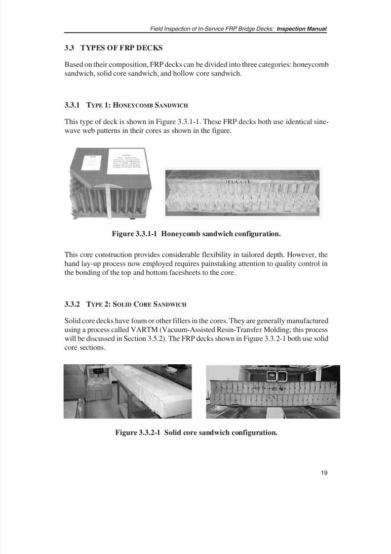
3.3.1 TYPE 1: HONEYCOMB SANDWICH
This type of deck is shown in Figure 3.3.1-1. These FRP decks both use identical sine-wave web patterns in their cores as shown in the figure.
Figure 3.3.1-1 Honeycomb sandwich configuration.
Figure 3.3.2-1 Solid core sandwich configuration.
This core construction provides considerable flexibility in tailored depth. However, thehand lay-up process now employed requires painstaking attention to quality control inthe bonding of the top and bottom facesheets to the core.
3.3.2 TYPE 2: SOLID CORE SANDWICH
Solid core decks have foam or other fillers in the cores. They are generally manufacturedusing a process called VARTM (Vacuum-Assisted Resin-Transfer Molding; this processwill be discussed in Section 3.5.2). The FRP decks shown in Figure 3.3.2-1 both use solidcore sections.
8/8/2019 Inspection of FRP Decks
http://slidepdf.com/reader/full/inspection-of-frp-decks 31/175
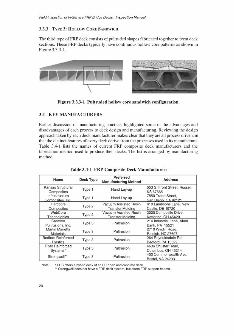
3.3.3 TYPE 3: HOLLOW CORE SANDWICH
The third type of FRP deck consists of pultruded shapes fabricated together to form deck sections. These FRP decks typically have continuous hollow core patterns as shown inFigure 3.3.3-1.
Field Inspection of In-Service FRP Bridge Decks: Inspection Manual
20
Figure 3.3.3-1 Pultruded hollow core sandwich configuration.
3.4 KEY MANUFACTURERS
Earlier discussion of manufacturing practices highlighted some of the advantages anddisadvantages of each process to deck design and manufacturing. Reviewing the designapproach taken by each deck manufacturer makes clear that they are all process driven, inthat the distinct features of every deck derive from the processes used in its manufacture.Table 3.4-1 lists the names of current FRP composite deck manufacturers and thefabrication method used to produce their decks. The list is arranged by manufacturingmethod.
Name Deck TypePreferred
Manufacturing MethodAddress
Kansas Structural
CompositesType 1 Hand Lay-up
553 S. Front Street, Russell,
KS 67665Infrastructure
Composites, Inc.Type 1 Hand Lay-up
7550 Trade Street,
San Diego, CA 92121Hardcore
CompositesType 2
Vacuum Assisted Resin
Transfer Molding
618 Lambsons Lane, New
Castle, DE 197202000 Composite Drive,
Kettering, OH 45420
WebCore
TechnologiesType 2
Vacuum Assisted Resin
Transfer Molding214 Industrial Lane, Alum
Bank, PA 15521
Creative
Pultrusions, Inc.Type 3 Pultrusion
Martin Marietta
Materials
Type 3 Pultrusion2710 Wycliff Road,
Raleigh, NC 27607Bedford Reinforced
PlasticsType 3 Pultrusion
264 Reynoldsdale Rd.,
Bedford, PA 15522Fiber Reinforced
Systems*Type 3 Pultrusion
4636 Shuster Road,
Columbus, OH 43214
Strongwell** Type 3 Pultrusion400 Commonwealth Ave.
Bristol, VA 24203
Note: * FRS offers a hybrid deck of an FRP pan and concrete deck.** Strongwell does not have a FRP deck system, but offers FRP support beams.
Table 3.4-1 FRP Composite Deck Manufacturers

8/8/2019 Inspection of FRP Decks
http://slidepdf.com/reader/full/inspection-of-frp-decks 32/175
21
Field Inspection of In-Service FRP Bridge Decks: Inspection Manual
3.5 DISCUSSION OF MANUFACTURING METHODS AND DECK TYPES
When fabricating components and structures from traditional construction materials,manufacturing is usually a matter of shaping, removing, and joining materials that arealready solid. With FRP composites the situation is somewhat different than withmetalworking (and, in some very specific ways, similar to casting) in that the material
and the physical component are manufactured at the same time. Clearly, the synergyrequired in the early stages of designing the component, in this case bridge decks, musttake into consideration how the component will be processed. This in turn influences thedesigner’s mixing of constituents and composition of the laminate(s). The designsdeveloped over the past decade distinctly reflect the manufacturing processes used tocreate them.
Since the 1950s, tremendous strides have been made in the processing of FRPcomposites; these strides have been motivated both by the need to reduce manufacturingcosts and by the industry’s desire to improve product quality and consistency. Alsoinstrumental in this progress are more stringent environmental pollution limits, which
are driving manufacturers away from open processes such as hand lay-up and towardmore captive and automated systems.
This section discusses the basics of manufacturing processes typically used formanufacturing all structural FRP components, not just bridge decks. The purpose is tointroduce readers to these methods and to show how differences in deck designs relateto the way they have been manufactured. The focus is on commercial processes ratherthan on such costly, high-precision methods as autoclave processing or high-pressureresin transfer molding, which are used in aerospace but not in deck manufacturing. Table3.4-1 lists the process methods and their current applicability to bridge deck manufacturing. General descriptions of the processes are given in the following sections.
3.5.1 HAND LAY-UP OR OPEN MOLDING
The hand lay-up process is the most fundamental method of manufacturing still widelyused in all industries. The basic procedure is shown in Figures 3.5.1-1 and 3.5.1-2. Fiberreinforcement is placed in position on the mold or plate and then saturated with resin. Acrew then uses specialized rollers and paddles to work the resin into the fabric, fullywetting the layer. After determining that the layer is fully wetted, the crew repeats theprocess on succeeding layers until the lamination is complete. The component is then left
to cure thoroughly, which takes from a few hours to overnight.

8/8/2019 Inspection of FRP Decks
http://slidepdf.com/reader/full/inspection-of-frp-decks 33/175
8/8/2019 Inspection of FRP Decks
http://slidepdf.com/reader/full/inspection-of-frp-decks 34/175
23
Field Inspection of In-Service FRP Bridge Decks: Inspection Manual
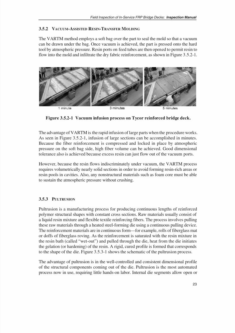
3.5.2 VACUUM-ASSISTED RESIN-TRANSFER MOLDING
The VARTM method employs a soft bag over the part to seal the mold so that a vacuumcan be drawn under the bag. Once vacuum is achieved, the part is pressed onto the hardtool by atmospheric pressure. Resin ports on feed tubes are then opened to permit resin toflow into the mold and infiltrate the dry fabric reinforcement, as shown in Figure 3.5.2-1.
Figure 3.5.2-1 Vacuum infusion process on Tycor reinforced bridge deck.
The advantage of VARTM is the rapid infusion of large parts when the procedure works.As seen in Figure 3.5.2-1, infusion of large sections can be accomplished in minutes.Because the fiber reinforcement is compressed and locked in place by atmosphericpressure on the soft bag side, high fiber volume can be achieved. Good dimensionaltolerance also is achieved because excess resin can just flow out of the vacuum ports.
However, because the resin flows indiscriminately under vacuum, the VARTM processrequires volumetrically nearly solid sections in order to avoid forming resin-rich areas or
resin pools in cavities. Also, any nonstructural materials such as foam core must be ableto sustain the atmospheric pressure without crushing.
3.5.3 PULTRUSION
Pultrusion is a manufacturing process for producing continuous lengths of reinforcedpolymer structural shapes with constant cross sections. Raw materials usually consist of a liquid resin mixture and flexible textile reinforcing fibers. The process involves pullingthese raw materials through a heated steel-forming die using a continuous pulling device.The reinforcement materials are in continuous form—for example, rolls of fiberglass mator doffs of fiberglass roving. As the reinforcement is saturated with the resin mixture inthe resin bath (called “wet-out”) and pulled through the die, heat from the die initiatesthe gelation (or hardening) of the resin. A rigid, cured profile is formed that correspondsto the shape of the die. Figure 3.5.3-1 shows the schematic of the pultrusion process.
The advantage of pultrusion is in the well-controlled and consistent dimensional profileof the structural components coming out of the die. Pultrusion is the most automatedprocess now in use, requiring little hands-on labor. Internal die segments allow open or

8/8/2019 Inspection of FRP Decks
http://slidepdf.com/reader/full/inspection-of-frp-decks 35/175
wrap-around shapes to be designed and details such as hollow tubes and trapezoids to beproduced.
Field Inspection of In-Service FRP Bridge Decks: Inspection Manual
24
* Caterpillar Pullers (shown) or Reciprocating Pullers
Figure 3.5.3-1 Schematic of the pultrusion process.
The disadvantage is that pultrusion produces long, narrow “barlike” profiles, so deck designs employing pultrusion must consider how to combine pultruded elements tocreate the necessary width.
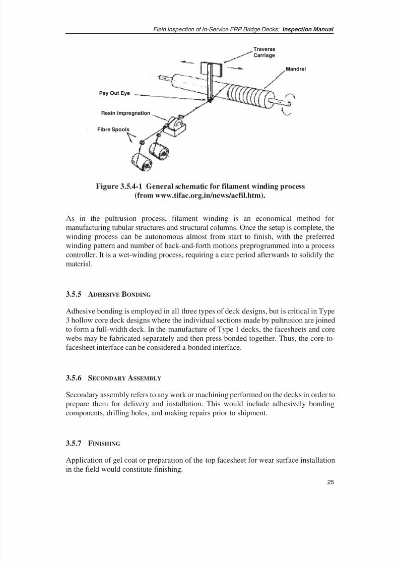
3.5.4 FILAMENT WINDING
Filament winding is the process of fabricating FRP components by wrapping wet rovingor fabric onto a single-axis rotating mandrel as shown in Figure 3.5.4-1. While no FRPbridge decks or components now in field service are being fabricated by the filamentwinding process, research and development of the process for fabricating deck components have been ongoing in the United States and Canada. For example, theUniversity of Illinois completed NCHRP-IDEA Project 63, “Manufacture and Testing of a Filament Wound Composite Bridge Superstructure,” demonstrating that filament
wound bridge components could be fabricated at the 1/10th scale size.
8/8/2019 Inspection of FRP Decks
http://slidepdf.com/reader/full/inspection-of-frp-decks 36/175
25
Field Inspection of In-Service FRP Bridge Decks: Inspection Manual
As in the pultrusion process, filament winding is an economical method formanufacturing tubular structures and structural columns. Once the setup is complete, thewinding process can be autonomous almost from start to finish, with the preferredwinding pattern and number of back-and-forth motions preprogrammed into a processcontroller. It is a wet-winding process, requiring a cure period afterwards to solidify thematerial.
3.5.5 ADHESIVE BONDING
Adhesive bonding is employed in all three types of deck designs, but is critical in Type3 hollow core deck designs where the individual sections made by pultrusion are joinedto form a full-width deck. In the manufacture of Type 1 decks, the facesheets and corewebs may be fabricated separately and then press bonded together. Thus, the core-to-facesheet interface can be considered a bonded interface.
3.5.6 SECONDARY ASSEMBLY
Secondary assembly refers to any work or machining performed on the decks in order toprepare them for delivery and installation. This would include adhesively bondingcomponents, drilling holes, and making repairs prior to shipment.
3.5.7 FINISHING
Application of gel coat or preparation of the top facesheet for wear surface installationin the field would constitute finishing.
TraverseCarriage
Mandrel
Pay Out Eye
Resin Impregnation
Fibre Spools
Figure 3.5.4-1 General schematic for filament winding process
(from www.tifac.org.in/news/acfil.htm).
8/8/2019 Inspection of FRP Decks
http://slidepdf.com/reader/full/inspection-of-frp-decks 37/175
3.6 GENERAL DELIVERY AND INSTALLATION PROCEDURE
Installation procedures for all deck types follow similar guidelines, which include
1. Delivery and acceptance inspection of the FRP decks,
2. Preparation of the bridge site according to specifications, and
3. Installation of the deck and other bridge components.
Installation specifications will dictate the connection method to be used for panel-to-panel connections and to anchor the decks to the superstructure. Specific installationprocedures are based on designer, owner agency, or manufacturer’s recommendations.Typically, the connection and anchoring methods selected are those that work best for aparticular deck design.
3.7 TYPICAL DECK INSTALLATION
The following sections provide information on typical FRP deck installation practice anddetails of various FRP deck components. The FRP deck inspector and inspector traineeis provided this resource for general familiarization with manufacture and fabricationtechniques. This manual is not intended to supplant FRP bridge deck installation manualsobtained for deck construction.
3.7.1 PANEL SIZES
The FRP deck is typically manufactured in panels that are later attached together in thefield. On bridges where the decks span in the transverse direction over longitudinalsuperstructure framing members such as stringers, the deck is composed of transversepanels 8 to 10 feet wide by about 30 feet long. These panels are typically 4 to 8 in. deepand serve as alternatives for conventional decks, meeting the existing roadway profilesand deck elevations. On bridges without superstructure elements supporting the deck,where the deck spans from abutment to abutment or from floor-beam to floor-beam, thedeck sections are usually much thicker, with panel widths of 8 to 10 feet and lengths thatsuit the spanned distance.
Generally, FRP decks are made as wide as is practical to transport (i.e., 8 to 10 feet) andas long as will fit on a flatbed trailer. Because of the size limitations, almost all decks are joined in the field to create a seamless final installation.
Field Inspection of In-Service FRP Bridge Decks: Inspection Manual
26

8/8/2019 Inspection of FRP Decks
http://slidepdf.com/reader/full/inspection-of-frp-decks 38/175
8/8/2019 Inspection of FRP Decks
http://slidepdf.com/reader/full/inspection-of-frp-decks 39/175
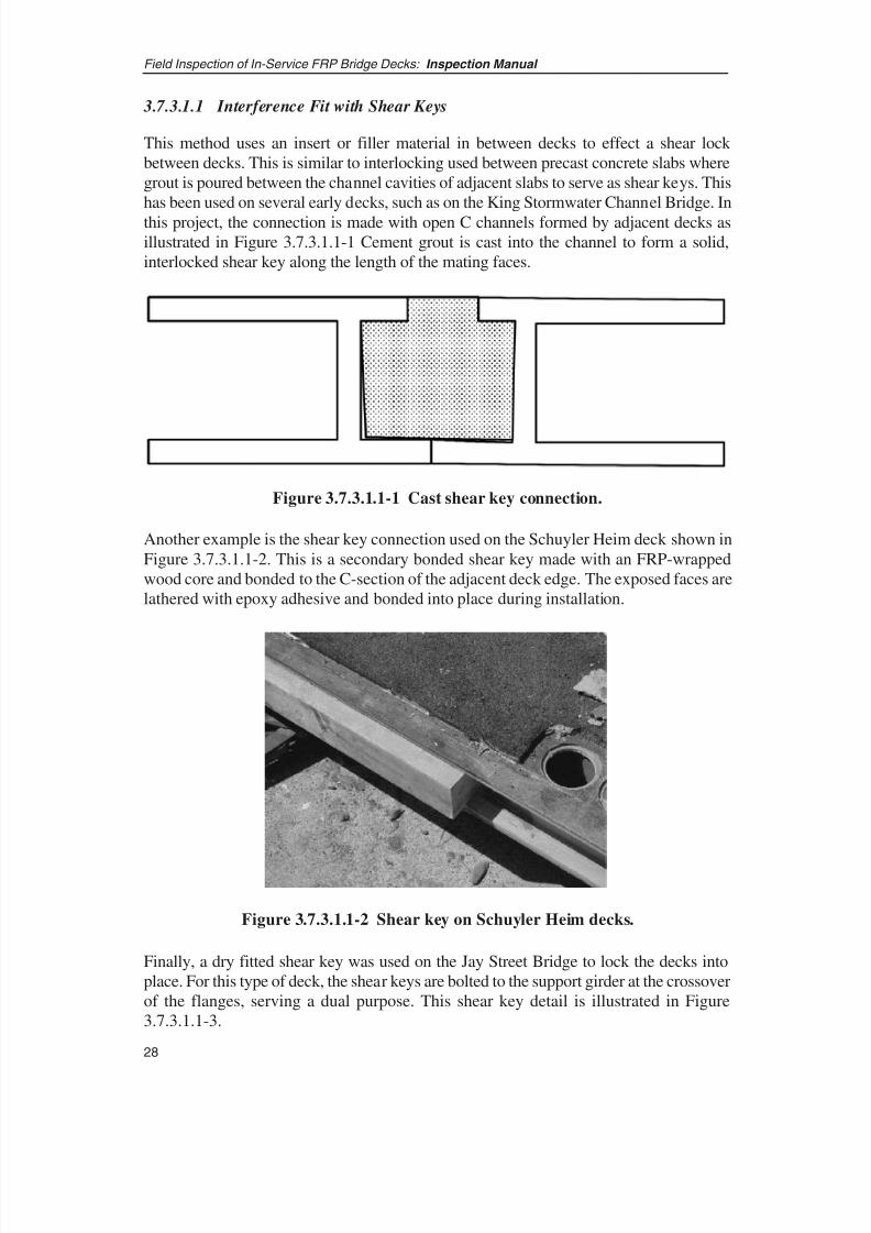
3.7.3.1.1 Interference Fit with Shear Keys
This method uses an insert or filler material in between decks to effect a shear lock between decks. This is similar to interlocking used between precast concrete slabs wheregrout is poured between the channel cavities of adjacent slabs to serve as shear keys. Thishas been used on several early decks, such as on the King Stormwater Channel Bridge. In
this project, the connection is made with open C channels formed by adjacent decks asillustrated in Figure 3.7.3.1.1-1 Cement grout is cast into the channel to form a solid,interlocked shear key along the length of the mating faces.
Field Inspection of In-Service FRP Bridge Decks: Inspection Manual
28
Figure 3.7.3.1.1-1 Cast shear key connection.
Figure 3.7.3.1.1-2 Shear key on Schuyler Heim decks.
Another example is the shear key connection used on the Schuyler Heim deck shown inFigure 3.7.3.1.1-2. This is a secondary bonded shear key made with an FRP-wrappedwood core and bonded to the C-section of the adjacent deck edge. The exposed faces arelathered with epoxy adhesive and bonded into place during installation.
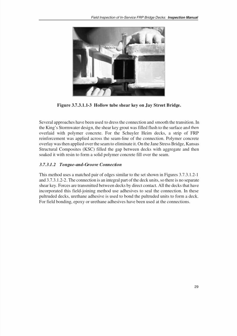
Finally, a dry fitted shear key was used on the Jay Street Bridge to lock the decks intoplace. For this type of deck, the shear keys are bolted to the support girder at the crossoverof the flanges, serving a dual purpose. This shear key detail is illustrated in Figure3.7.3.1.1-3.
8/8/2019 Inspection of FRP Decks
http://slidepdf.com/reader/full/inspection-of-frp-decks 40/175
29
Field Inspection of In-Service FRP Bridge Decks: Inspection Manual
Several approaches have been used to dress the connection and smooth the transition. Inthe King’s Stormwater design, the shear key grout was filled flush to the surface and thenoverlaid with polymer concrete. For the Schuyler Heim decks, a strip of FRPreinforcement was applied across the seam-line of the connection. Polymer concreteoverlay was then applied over the seam to eliminate it. On the Jane Stress Bridge, KansasStructural Composites (KSC) filled the gap between decks with aggregate and thensoaked it with resin to form a solid polymer concrete fill over the seam.
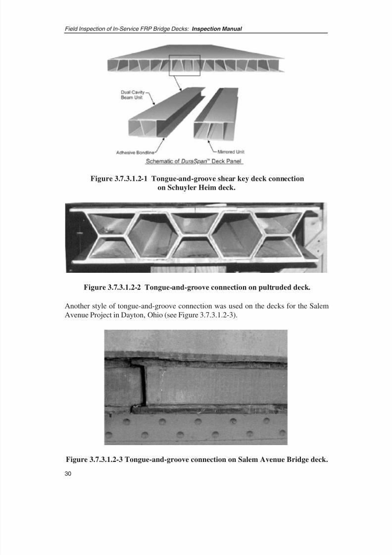
3.7.3.1.2 Tongue-and-Groove Connection
This method uses a matched pair of edges similar to the set shown in Figures 3.7.3.1.2-1and 3.7.3.1.2-2. The connection is an integral part of the deck units, so there is no separateshear key. Forces are transmitted between decks by direct contact. All the decks that haveincorporated this field-joining method use adhesives to seal the connection. In thesepultruded decks, urethane adhesive is used to bond the pultruded units to form a deck.For field bonding, epoxy or urethane adhesives have been used at the connections.
Figure 3.7.3.1.1-3 Hollow tube shear key on Jay Street Bridge.
8/8/2019 Inspection of FRP Decks
http://slidepdf.com/reader/full/inspection-of-frp-decks 41/175
Field Inspection of In-Service FRP Bridge Decks: Inspection Manual
30
Figure 3.7.3.1.2-1 Tongue-and-groove shear key deck connection
on Schuyler Heim deck.
Figure 3.7.3.1.2-2 Tongue-and-groove connection on pultruded deck.
Figure 3.7.3.1.2-3 Tongue-and-groove connection on Salem Avenue Bridge deck.
Another style of tongue-and-groove connection was used on the decks for the SalemAvenue Project in Dayton, Ohio (see Figure 3.7.3.1.2-3).

8/8/2019 Inspection of FRP Decks
http://slidepdf.com/reader/full/inspection-of-frp-decks 42/175
In general, the installation procedure involves the following steps:
• Prepare the surfaces of the joining faces,
• Apply the adhesive to one of the faces,
• Press the decks together to squeeze the joint shut and smear the adhesive over thecontact faces, and
• Let stand until cured.
3.7.3.1.3 Butt Joints with Shear Splice Plate Strips
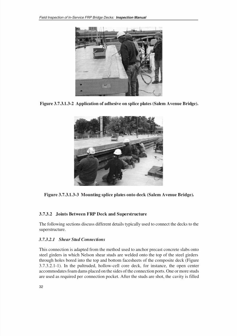
This method uses a butt joint between adjacent decks with splice plates field-bonded tothe top and bottom of the decks to transfer load as shown in Figure 3.7.3.1.3-1. Thistechnique was used on the Salem Avenue Bridge. In this installation, adhesive is applied
to the edge of the decks to be connected (see Figure 3.7.3.1.3-2), and then the slice platestrips are bonded to the top and bottom of the decks (see Figure 3.7.3.1.3-3). Self-tappingscrews were used to keep the splice strips in place while the adhesive cured. Currently,only one manufacturer has used this type of deck-to-deck connection.
31
Field Inspection of In-Service FRP Bridge Decks: Inspection Manual
Figure 3.7.3.1.3-1 Detail of deck-to-deck joint (Salem Avenue Bridge).
8/8/2019 Inspection of FRP Decks
http://slidepdf.com/reader/full/inspection-of-frp-decks 43/175
3.7.3.2 Joints Between FRP Deck and Superstructure
The following sections discuss different details typically used to connect the decks to thesuperstructure.
3.7.3.2.1 Shear Stud Connections
This connection is adapted from the method used to anchor precast concrete slabs ontosteel girders in which Nelson shear studs are welded onto the top of the steel girdersthrough holes bored into the top and bottom facesheets of the composite deck (Figure3.7.3.2.1-1). In the pultruded, hollow-cell core deck, for instance, the open centeraccommodates foam dams placed on the sides of the connection ports. One or more studsare used as required per connection pocket. After the studs are shot, the cavity is filled
Field Inspection of In-Service FRP Bridge Decks: Inspection Manual
32
Figure 3.7.3.1.3-2 Application of adhesive on splice plates (Salem Avenue Bridge).
Figure 3.7.3.1.3-3 Mounting splice plates onto deck (Salem Avenue Bridge).

8/8/2019 Inspection of FRP Decks
http://slidepdf.com/reader/full/inspection-of-frp-decks 44/175
33
Field Inspection of In-Service FRP Bridge Decks: Inspection Manual
with grout to lock in the studs and deck. This setup is repeated down the length of thegirder in a predetermined spacing based on design requirements.
To take up the irregularities between the girders and deck, a haunch is typically built upby flowing grout beneath the decks into the cavity between the top of the girder andbottom of the deck. The preparation of this is as shown in Figure 3.7.3.2.1-2.
Figure 3.7.3.2.1-1 Typical shear stud connections.
Figure 3.7.3.2.1-2 - Deck being laid down on steel girders; note the channel
formed on the top flange for casting haunches.

8/8/2019 Inspection of FRP Decks
http://slidepdf.com/reader/full/inspection-of-frp-decks 45/175
3.7.3.2.2 Cast-in-Place Connections
This connection is similar to the shear stud connection except that a different shearingmember is used. In the King Stormwater bridge, a set of bent reinforcement bars cast intothe underlying concrete-filled tubular girders act as the shear studs.
3.7.3.2.3 Clip Connections
This style of connection anchors the deck to the girders by vertically clamping it to thegirder flange with steel side clips. Examples of these types of connections are shown inFigures 3.7.3.2.3-1 and 3.7.3.2.3-2 for the Jay Street Bridge.
Field Inspection of In-Service FRP Bridge Decks: Inspection Manual
34
Figure 3.7.3.2.3-1 Anchor clips used on Jay Street Bridge.
Figure 3.7.3.2.3-2 Girder clips for Jay Street Bridge.

8/8/2019 Inspection of FRP Decks
http://slidepdf.com/reader/full/inspection-of-frp-decks 46/175
35
Field Inspection of In-Service FRP Bridge Decks: Inspection Manual
3.7.3.2.4 Bolted Connection
This connection uses threaded Nelson studs to anchor composite decks onto steel girders.Like the shear stud, the threaded stud is welded to the girder through predrilled holes inthe deck, as shown in Figures 3.7.3.2.4-1 and 3.7.3.2.4-2. This was used on the SchuylerHeim Bridge project. After the stud is secured, nuts and washers are torqued onto the
bolts to lock down the deck. The nuts are secured with thread-lock, sealed, and the topfacesheet holes are covered with a cap and wear surface.
Figure 3.7.3.2.4-1 Carbon/fiberglass deck being installed in the
Schuyler Heim lift bridge.
Figure 3.7.3.2.4-2 - Decks are secured to girders through bolted connections.
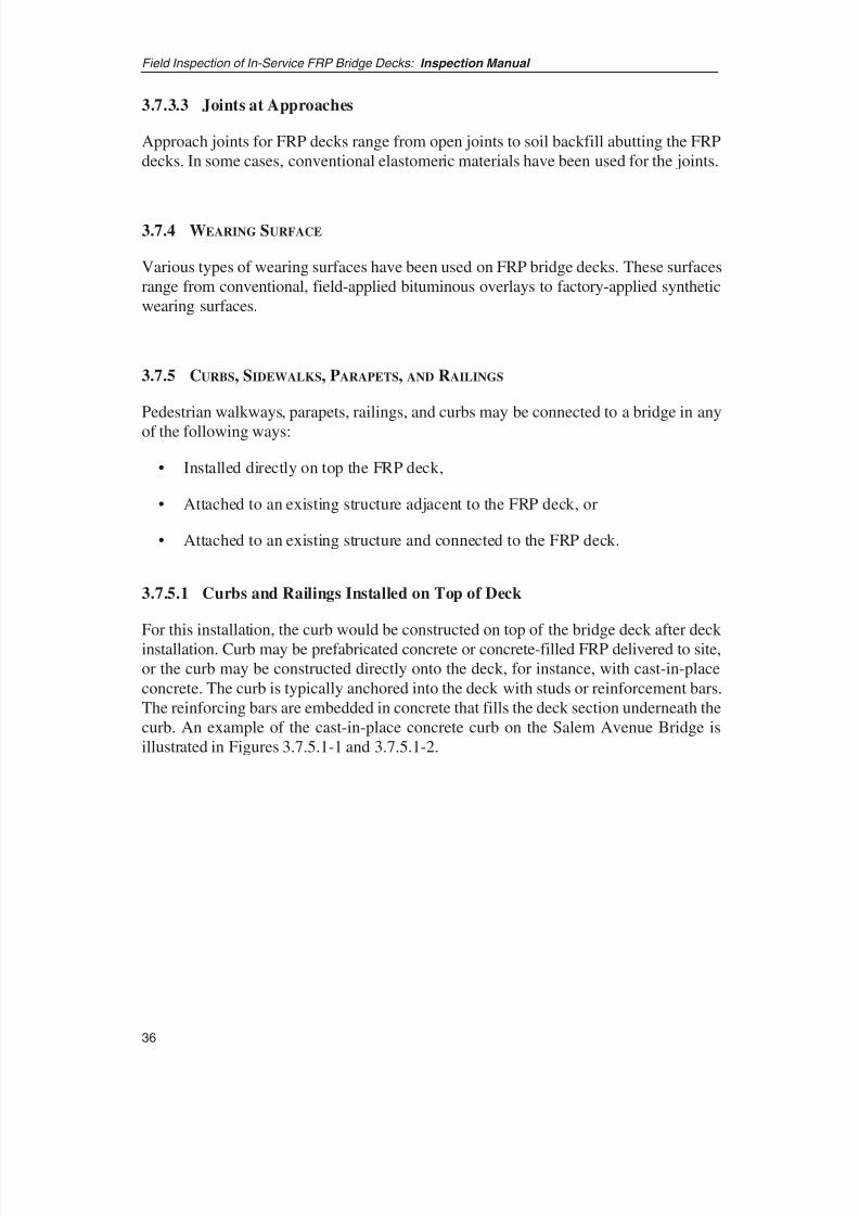
8/8/2019 Inspection of FRP Decks
http://slidepdf.com/reader/full/inspection-of-frp-decks 47/175
3.7.3.3 Joints at Approaches
Approach joints for FRP decks range from open joints to soil backfill abutting the FRPdecks. In some cases, conventional elastomeric materials have been used for the joints.
3.7.4 WEARING SURFACE
Various types of wearing surfaces have been used on FRP bridge decks. These surfacesrange from conventional, field-applied bituminous overlays to factory-applied syntheticwearing surfaces.
3.7.5 CURBS, SIDEWALKS, PARAPETS, AND RAILINGS
Pedestrian walkways, parapets, railings, and curbs may be connected to a bridge in any
of the following ways:
• Installed directly on top the FRP deck,
• Attached to an existing structure adjacent to the FRP deck, or
• Attached to an existing structure and connected to the FRP deck.
3.7.5.1 Curbs and Railings Installed on Top of Deck
For this installation, the curb would be constructed on top of the bridge deck after deck installation. Curb may be prefabricated concrete or concrete-filled FRP delivered to site,or the curb may be constructed directly onto the deck, for instance, with cast-in-placeconcrete. The curb is typically anchored into the deck with studs or reinforcement bars.The reinforcing bars are embedded in concrete that fills the deck section underneath thecurb. An example of the cast-in-place concrete curb on the Salem Avenue Bridge isillustrated in Figures 3.7.5.1-1 and 3.7.5.1-2.
Field Inspection of In-Service FRP Bridge Decks: Inspection Manual
36
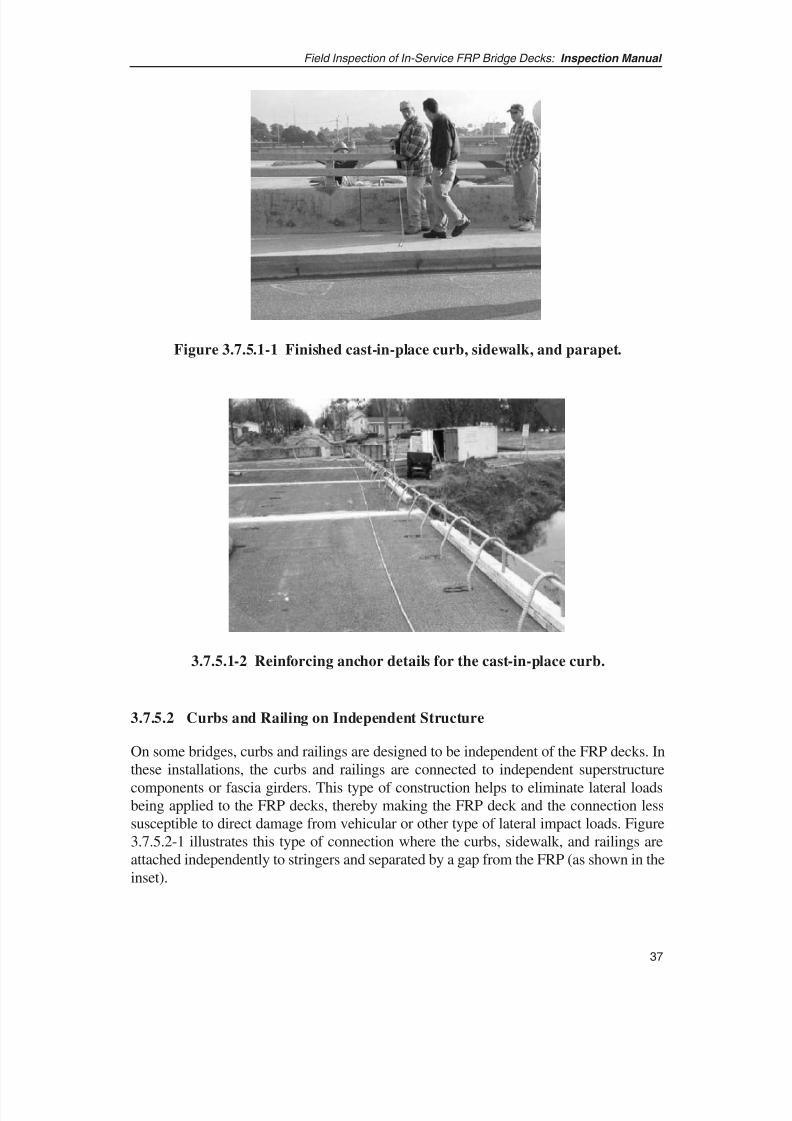
8/8/2019 Inspection of FRP Decks
http://slidepdf.com/reader/full/inspection-of-frp-decks 48/175
37
Field Inspection of In-Service FRP Bridge Decks: Inspection Manual
3.7.5.2 Curbs and Railing on Independent Structure
On some bridges, curbs and railings are designed to be independent of the FRP decks. Inthese installations, the curbs and railings are connected to independent superstructure
components or fascia girders. This type of construction helps to eliminate lateral loadsbeing applied to the FRP decks, thereby making the FRP deck and the connection lesssusceptible to direct damage from vehicular or other type of lateral impact loads. Figure3.7.5.2-1 illustrates this type of connection where the curbs, sidewalk, and railings areattached independently to stringers and separated by a gap from the FRP (as shown in theinset).
Figure 3.7.5.1-1 Finished cast-in-place curb, sidewalk, and parapet.
3.7.5.1-2 Reinforcing anchor details for the cast-in-place curb.
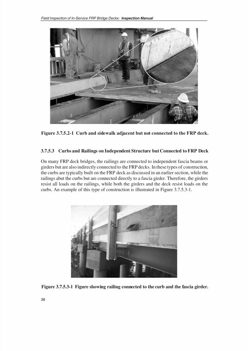
8/8/2019 Inspection of FRP Decks
http://slidepdf.com/reader/full/inspection-of-frp-decks 49/175

8/8/2019 Inspection of FRP Decks
http://slidepdf.com/reader/full/inspection-of-frp-decks 50/175
39
Field Inspection of In-Service FRP Bridge Decks: Inspection Manual
SECTION 4: SIGNIFICANT DECK DETAILS AND DAMAGE TYPES
4.1 OVERVIEW
This section presents FRP deck details and damage types and, in conjunction withSection 3, allows the inspector to understand the areas that need special emphasis duringinspection. It also prepares the reader to understand the inspection techniques presentedin Section 5.
Inspection of installed FRP decks covers two main areas: the external bridge componentsattached to or in the vicinity of an FRP deck and the deck element itself. More
specifically, these two areas encompass
• External details—all the components and appurtenances on or near FRP decksthat might be critical, directly or indirectly, for FRP bridge safety. This includesconnections, joints, curbs, sidewalks, railings, and other such components of abridge.
• Internal details—the FRP deck section itself, and includes the facesheets, cores,web components, and panel edges.
These details and intrinsic aging characteristics are described in detail in the followingsections.
4.2 DECK EXTERNAL DETAILS
These details and locations should be inspected and evaluated during any inspection of FRP decks because they are likely to exhibit the first signs of distress that, if notidentified and alleviated, could spread to larger areas. Figures 4.2.1-1 illustrating panel-to-panel connections and 4.2.2-1 illustrating deck-to-girder connections appear on pages43 and 44.
4.2.1 PANEL-TO-PANEL CONNECTIONS
As discussed in Section 3, there exist several types of panel-to-panel connections. Thepanel-to-panel connection is probably the most accessible part of the bridge deck. It is alsothe most likely part of the deck system to develop problems because of improperinstallation, environmental swings, or excess loading. Experience with the Salem AvenueBridge Project and ad hoc inspection/observation of bridge decks on the King StormwaterChannel, Tech 21, and Darke County bridges have shown that the first instance of
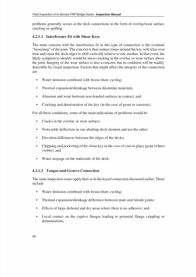
8/8/2019 Inspection of FRP Decks
http://slidepdf.com/reader/full/inspection-of-frp-decks 51/175
problems generally occurs at the deck connections in the form of overlay/wear surfacecracking or spalling.
4.2.1.1 Interference Fit with Shear Keys
The main concern with the interference fit in this type of connection is the eventual
“loosening” of the joint. The concern is that contact zones around the key will relax overtime and cause the deck edges to shift vertically relative to one another. In that event, thelikely symptom to identify would be stress cracking in the overlay or wear surface abovethe joint. Integrity of the wear surface is also a concern, but its condition will be readilydetectible by visual inspection. Factors that might affect the integrity of the connectionare
• Water intrusion combined with freeze-thaw cycling;
• Thermal expansion/shrinkage between dissimilar materials;
• Abrasion and wear between non-bonded surfaces in contact; and
• Cracking and deterioration of the key (in the case of grout or concrete).
For all these conditions, some of the main indications of problems would be
• Cracks in the overlay or wear surface;
• Noticeable deflection in one abutting deck element and not the other;
• Elevation differences between the edges of the decks;
• Chipping and pocketing of the shear key in the case of cast-in-place grout (wherevisible); and
• Water seepage on the underside of the deck.
4.2.1.2 Tongue-and-Groove Connection
The same inspection issues apply here as in the keyed connection discussed earlier. Theseinclude
• Water intrusion combined with freeze-thaw cycling;
• Thermal expansion/shrinkage difference between male and female joints;
• Effects of large disbond and dry areas where there is no adhesive; and
• Local contact on the captive flanges leading to potential flange crippling ordelaminations.
Field Inspection of In-Service FRP Bridge Decks: Inspection Manual
40
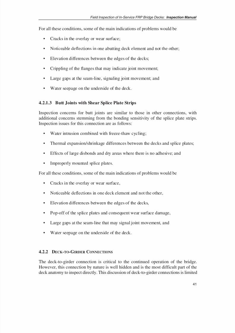
8/8/2019 Inspection of FRP Decks
http://slidepdf.com/reader/full/inspection-of-frp-decks 52/175
41
Field Inspection of In-Service FRP Bridge Decks: Inspection Manual
For all these conditions, some of the main indications of problems would be
• Cracks in the overlay or wear surface;
• Noticeable deflections in one abutting deck element and not the other;
• Elevation differences between the edges of the decks;
• Crippling of the flanges that may indicate joint movement;
• Large gaps at the seam-line, signaling joint movement; and
• Water seepage on the underside of the deck.
4.2.1.3 Butt Joints with Shear Splice Plate Strips
Inspection concerns for butt joints are similar to those in other connections, with
additional concerns stemming from the bonding sensitivity of the splice plate strips.Inspection issues for this connection are as follows:
• Water intrusion combined with freeze-thaw cycling;
• Thermal expansion/shrinkage differences between the decks and splice plates;
• Effects of large disbonds and dry areas where there is no adhesive; and
• Improperly mounted splice plates.
For all these conditions, some of the main indications of problems would be
• Cracks in the overlay or wear surface,
• Noticeable deflections in one deck element and not the other,
• Elevation differences between the edges of the decks,
• Pop-off of the splice plates and consequent wear surface damage,
• Large gaps at the seam-line that may signal joint movement, and
• Water seepage on the underside of the deck.
4.2.2 DECK-TO-GIRDER CONNECTIONS
The deck-to-girder connection is critical to the continued operation of the bridge.However, this connection by nature is well hidden and is the most difficult part of thedeck anatomy to inspect directly. This discussion of deck-to-girder connections is limited
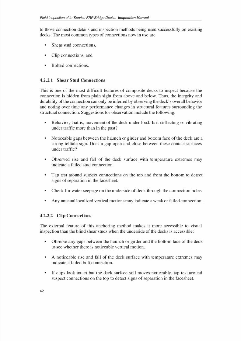
8/8/2019 Inspection of FRP Decks
http://slidepdf.com/reader/full/inspection-of-frp-decks 53/175
to those connection details and inspection methods being used successfully on existingdecks. The most common types of connections now in use are
• Shear stud connections,
• Clip connections, and
• Bolted connections.
4.2.2.1 Shear Stud Connections
This is one of the most difficult features of composite decks to inspect because theconnection is hidden from plain sight from above and below. Thus, the integrity anddurability of the connection can only be inferred by observing the deck’s overall behaviorand noting over time any performance changes in structural features surrounding thestructural connection. Suggestions for observation include the following:
• Behavior, that is, movement of the deck under load. Is it deflecting or vibratingunder traffic more than in the past?
• Noticeable gaps between the haunch or girder and bottom face of the deck are astrong telltale sign. Does a gap open and close between these contact surfacesunder traffic?
• Observed rise and fall of the deck surface with temperature extremes mayindicate a failed stud connection.
• Tap test around suspect connections on the top and from the bottom to detect
signs of separation in the facesheet.
• Check for water seepage on the underside of deck through the connection holes.
• Any unusual localized vertical motions may indicate a weak or failed connection.
4.2.2.2 Clip Connections
The external feature of this anchoring method makes it more accessible to visualinspection than the blind shear studs when the underside of the decks is accessible:
• Observe any gaps between the haunch or girder and the bottom face of the deck to see whether there is noticeable vertical motion.
• A noticeable rise and fall of the deck surface with temperature extremes mayindicate a failed bolt connection.
• If clips look intact but the deck surface still moves noticeably, tap test aroundsuspect connections on the top to detect signs of separation in the facesheet.
Field Inspection of In-Service FRP Bridge Decks: Inspection Manual
42
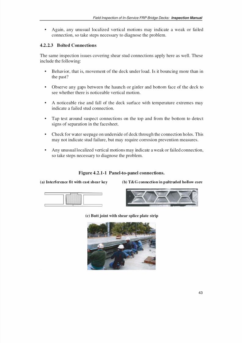
8/8/2019 Inspection of FRP Decks
http://slidepdf.com/reader/full/inspection-of-frp-decks 54/175
43
Field Inspection of In-Service FRP Bridge Decks: Inspection Manual
• Again, any unusual localized vertical motions may indicate a weak or failedconnection, so take steps necessary to diagnose the problem.
4.2.2.3 Bolted Connections
The same inspection issues covering shear stud connections apply here as well. These
include the following:
• Behavior, that is, movement of the deck under load. Is it bouncing more than inthe past?
• Observe any gaps between the haunch or girder and bottom face of the deck tosee whether there is noticeable vertical motion.
• A noticeable rise and fall of the deck surface with temperature extremes mayindicate a failed stud connection.
• Tap test around suspect connections on the top and from the bottom to detectsigns of separation in the facesheet.
• Check for water seepage on underside of deck through the connection holes. Thismay not indicate stud failure, but may require corrosion prevention measures.
• Any unusual localized vertical motions may indicate a weak or failed connection,so take steps necessary to diagnose the problem.
Figure 4.2.1-1 Panel-to-panel connections.
(a) Interference fit with cast shear key (b) T&G connection in pultruded hollow core
(c) Butt joint with shear splice plate strip
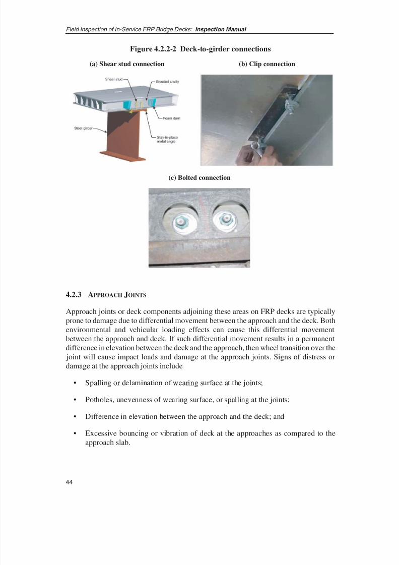
8/8/2019 Inspection of FRP Decks
http://slidepdf.com/reader/full/inspection-of-frp-decks 55/175
4.2.3 APPROACH JOINTS
Approach joints or deck components adjoining these areas on FRP decks are typicallyprone to damage due to differential movement between the approach and the deck. Bothenvironmental and vehicular loading effects can cause this differential movementbetween the approach and deck. If such differential movement results in a permanentdifference in elevation between the deck and the approach, then wheel transition over the joint will cause impact loads and damage at the approach joints. Signs of distress ordamage at the approach joints include
• Spalling or delamination of wearing surface at the joints;
• Potholes, unevenness of wearing surface, or spalling at the joints;
• Difference in elevation between the approach and the deck; and
• Excessive bouncing or vibration of deck at the approaches as compared to theapproach slab.
Field Inspection of In-Service FRP Bridge Decks: Inspection Manual
44
(a) Shear stud connection (b) Clip connection
(c) Bolted connection
Figure 4.2.2-2 Deck-to-girder connections

8/8/2019 Inspection of FRP Decks
http://slidepdf.com/reader/full/inspection-of-frp-decks 56/175
45
Field Inspection of In-Service FRP Bridge Decks: Inspection Manual
4.2.4 WEARING SURFACES
Important areas for inspection of wearing surfaces include areas around interfaces suchas scuppers, curbs, and approach joints. Areas over panel-to-panel joints also aresusceptible to damage or deterioration. The wearing surface is intrinsically susceptibleto wear and tear as well as to vehicle-induced impact damage. It is also susceptible to
construction quality and workmanship-related defects that could worsen while under use.Delamination, air pockets, peel off, potholes, and other such defects might therefore befound anywhere on the wearing surface.
During inspection, specifically look out for
• Delamination of the wearing surface;
• Unevenness, waviness, air pockets, and similar signs;
• Signs of abrasion, skid marks, potholes, and discoloration; and
• Separation and peeling off of wearing surface from the deck at joints, scuppers,and other interfaces.
4.2.5 CURBS, SIDEWALKS, PARAPETS, AND RAILINGS
Curbs, sidewalks, parapets, and railings are susceptible to horizontal loads that,depending on the connection details, can adversely affect FRP decks. Potential damageto the FRP deck may therefore be identified indirectly by noting distress or damage tothe curbs, parapets, and railings. Some particular signs of distress and damage to look
for include the following:
• Spalls, cracks, wheel marks, and other signs of impact on curbs;
• Signs of cracks and spalls at the curb-deck interface;
• Signs of distress and cracks where the curbs connect to the deck;
• Signs of vehicular or other impact on parapets and railings;
• Connections of railings or parapets to the deck;
• Damage, large deformations, dents, or bends in railings;
• Large spalls and cracks on parapets; and
• Cracks or other damage on the undersurface of the deck directly beneath thecurbs, parapets, or railings.
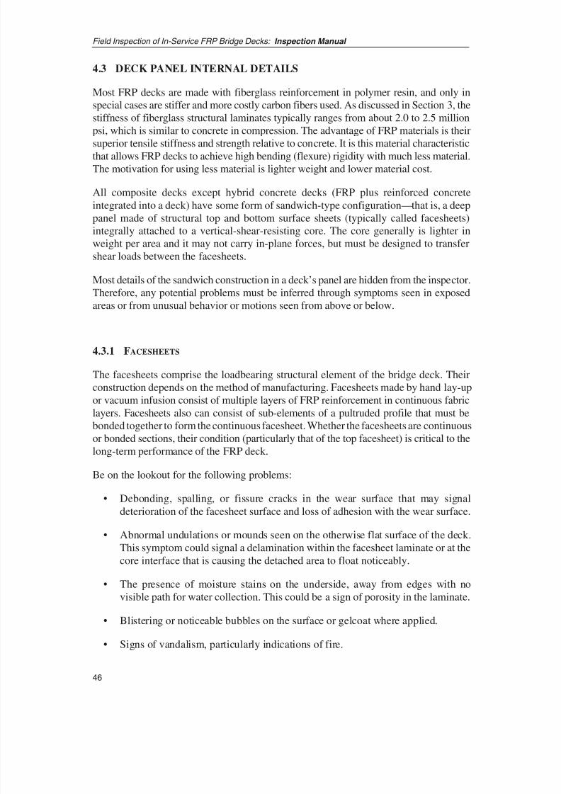
8/8/2019 Inspection of FRP Decks
http://slidepdf.com/reader/full/inspection-of-frp-decks 57/175
4.3 DECK PANEL INTERNAL DETAILS
Most FRP decks are made with fiberglass reinforcement in polymer resin, and only inspecial cases are stiffer and more costly carbon fibers used. As discussed in Section 3, thestiffness of fiberglass structural laminates typically ranges from about 2.0 to 2.5 millionpsi, which is similar to concrete in compression. The advantage of FRP materials is their
superior tensile stiffness and strength relative to concrete. It is this material characteristicthat allows FRP decks to achieve high bending (flexure) rigidity with much less material.The motivation for using less material is lighter weight and lower material cost.
All composite decks except hybrid concrete decks (FRP plus reinforced concreteintegrated into a deck) have some form of sandwich-type configuration—that is, a deeppanel made of structural top and bottom surface sheets (typically called facesheets)integrally attached to a vertical-shear-resisting core. The core generally is lighter inweight per area and it may not carry in-plane forces, but must be designed to transfershear loads between the facesheets.
Most details of the sandwich construction in a deck’s panel are hidden from the inspector.Therefore, any potential problems must be inferred through symptoms seen in exposedareas or from unusual behavior or motions seen from above or below.
4.3.1 FACESHEETS
The facesheets comprise the loadbearing structural element of the bridge deck. Theirconstruction depends on the method of manufacturing. Facesheets made by hand lay-upor vacuum infusion consist of multiple layers of FRP reinforcement in continuous fabric
layers. Facesheets also can consist of sub-elements of a pultruded profile that must bebonded together to form the continuous facesheet. Whether the facesheets are continuousor bonded sections, their condition (particularly that of the top facesheet) is critical to thelong-term performance of the FRP deck.
Be on the lookout for the following problems:
• Debonding, spalling, or fissure cracks in the wear surface that may signaldeterioration of the facesheet surface and loss of adhesion with the wear surface.
• Abnormal undulations or mounds seen on the otherwise flat surface of the deck.This symptom could signal a delamination within the facesheet laminate or at the
core interface that is causing the detached area to float noticeably.
• The presence of moisture stains on the underside, away from edges with novisible path for water collection. This could be a sign of porosity in the laminate.
• Blistering or noticeable bubbles on the surface or gelcoat where applied.
• Signs of vandalism, particularly indications of fire.
Field Inspection of In-Service FRP Bridge Decks: Inspection Manual
46
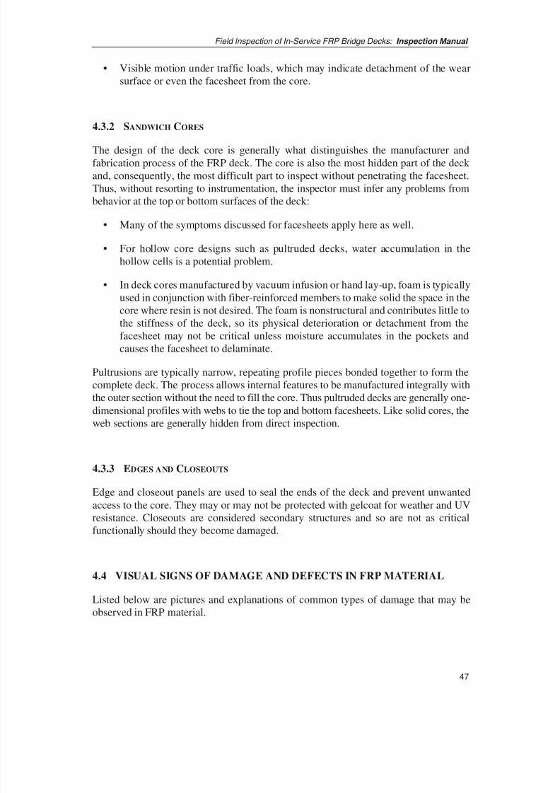
8/8/2019 Inspection of FRP Decks
http://slidepdf.com/reader/full/inspection-of-frp-decks 58/175
47
Field Inspection of In-Service FRP Bridge Decks: Inspection Manual
• Visible motion under traffic loads, which may indicate detachment of the wearsurface or even the facesheet from the core.
4.3.2 SANDWICH CORES
The design of the deck core is generally what distinguishes the manufacturer andfabrication process of the FRP deck. The core is also the most hidden part of the deck and, consequently, the most difficult part to inspect without penetrating the facesheet.Thus, without resorting to instrumentation, the inspector must infer any problems frombehavior at the top or bottom surfaces of the deck:
• Many of the symptoms discussed for facesheets apply here as well.
• For hollow core designs such as pultruded decks, water accumulation in thehollow cells is a potential problem.
• In deck cores manufactured by vacuum infusion or hand lay-up, foam is typicallyused in conjunction with fiber-reinforced members to make solid the space in thecore where resin is not desired. The foam is nonstructural and contributes little tothe stiffness of the deck, so its physical deterioration or detachment from thefacesheet may not be critical unless moisture accumulates in the pockets andcauses the facesheet to delaminate.
Pultrusions are typically narrow, repeating profile pieces bonded together to form thecomplete deck. The process allows internal features to be manufactured integrally withthe outer section without the need to fill the core. Thus pultruded decks are generally one-dimensional profiles with webs to tie the top and bottom facesheets. Like solid cores, theweb sections are generally hidden from direct inspection.
4.3.3 EDGES AND CLOSEOUTS
Edge and closeout panels are used to seal the ends of the deck and prevent unwantedaccess to the core. They may or may not be protected with gelcoat for weather and UVresistance. Closeouts are considered secondary structures and so are not as criticalfunctionally should they become damaged.
4.4 VISUAL SIGNS OF DAMAGE AND DEFECTS IN FRP MATERIAL
Listed below are pictures and explanations of common types of damage that may beobserved in FRP material.

8/8/2019 Inspection of FRP Decks
http://slidepdf.com/reader/full/inspection-of-frp-decks 59/175
4.4.1 BLISTERING
Blistering appears as surface bubbles on exposed laminate surfaces or gelcoated surfacesas shown in Figure 4.4.1-1. In the marine industry, blisters are generally attributed toosmosis of moisture into the laminate that exerts local hydrostatic pressure betweenlayers, causing delamination and subsequent bubbling. This is normally a problem for
marine craft because of the thinness of the shell. In FRP deck panels, osmosis to a degreethat would cause blistering is rare. Trapped moisture subjected to freeze-thaw cyclescould possibly cause this phenomenon, but it would most likely affect only the surfacelayer and not impact the deck’s structural performance.
Field Inspection of In-Service FRP Bridge Decks: Inspection Manual
48
Figure 4.4.1-1 Blistering on a gelcoated or laminated surface.
4.4.2 VOIDS
Voids are submerged gaps within the laminates of a deck and are usually invisible if thecomposite laminate resin is pigmented or the surface is painted or gelcoated. If the voidis large enough and grows progressively, it may appear as a crack on the surface. Anexample of this is shown in Figure 4.4.2-1 where the closeout of a foam-filled deck contained a large void that revealed itself as a surface crack along the closeout’s edge.
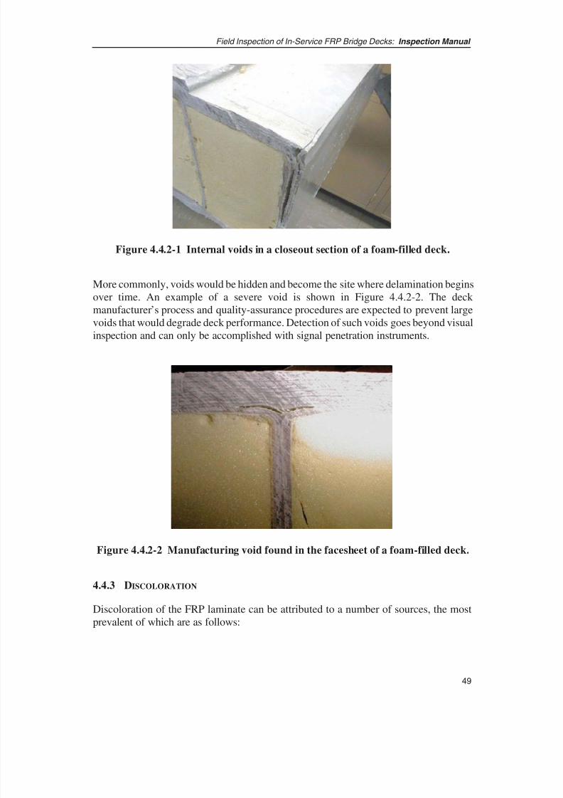
8/8/2019 Inspection of FRP Decks
http://slidepdf.com/reader/full/inspection-of-frp-decks 60/175
49
Field Inspection of In-Service FRP Bridge Decks: Inspection Manual
More commonly, voids would be hidden and become the site where delamination beginsover time. An example of a severe void is shown in Figure 4.4.2-2. The deck manufacturer’s process and quality-assurance procedures are expected to prevent largevoids that would degrade deck performance. Detection of such voids goes beyond visualinspection and can only be accomplished with signal penetration instruments.
Figure 4.4.2-1 Internal voids in a closeout section of a foam-filled deck.
Figure 4.4.2-2 Manufacturing void found in the facesheet of a foam-filled deck.
4.4.3 DISCOLORATION
Discoloration of the FRP laminate can be attributed to a number of sources, the mostprevalent of which are as follows:

8/8/2019 Inspection of FRP Decks
http://slidepdf.com/reader/full/inspection-of-frp-decks 61/175
• Chemical reaction, surface deterioration due to prolonged UV light exposure, orexposure to intense heat or fire.
• Crazing and whitening from excessive strain, visible mainly on clear resins.
• Subsurface voids seen in clear resins because of poor wet-out or incomplete
saturation. This is more a problem in manual hand lay-up processes.
• Moisture permeation of uncoated exposed resin, generally called “blushing.”
• Changes in pigmentation by manufacturer. This is not a structural problem.
4.4.4 WRINKLING
Fabric wrinkling is shown in Figure 4.4.4-1 and generally occurs because of excessivestretching or shearing of the fabric during wet-out. It is not a structural problem unlessit interferes with the proper surface contact at the connection or impedes the bonding of the wear surface.
Field Inspection of In-Service FRP Bridge Decks: Inspection Manual
50
Figure 4.4.4-1 Fabric wrinkling in laminated facesheet.
4.4.5 FIBER EXPOSURE
In this damage scenario, the laminate exhibits fiber brooming or environmental exposurebecause of prior damage in handling as shown in Figure 4.4.5-1. Left unattended, thedamage would make the fibers susceptible to moisture and contamination, leading tofurther laminate deterioration in the area.
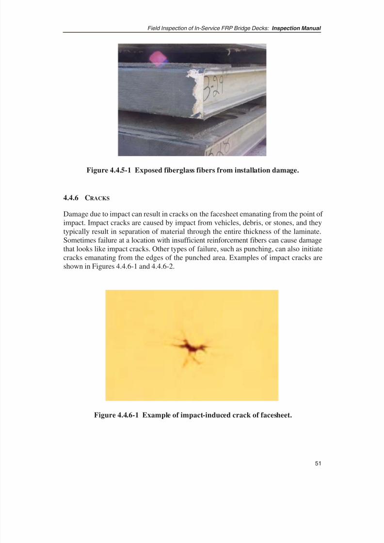
8/8/2019 Inspection of FRP Decks
http://slidepdf.com/reader/full/inspection-of-frp-decks 62/175
51
Field Inspection of In-Service FRP Bridge Decks: Inspection Manual
4.4.6 CRACKS
Damage due to impact can result in cracks on the facesheet emanating from the point of impact. Impact cracks are caused by impact from vehicles, debris, or stones, and theytypically result in separation of material through the entire thickness of the laminate.Sometimes failure at a location with insufficient reinforcement fibers can cause damagethat looks like impact cracks. Other types of failure, such as punching, can also initiatecracks emanating from the edges of the punched area. Examples of impact cracks areshown in Figures 4.4.6-1 and 4.4.6-2.
Figure 4.4.5-1 Exposed fiberglass fibers from installation damage.
Figure 4.4.6-1 Example of impact-induced crack of facesheet.

8/8/2019 Inspection of FRP Decks
http://slidepdf.com/reader/full/inspection-of-frp-decks 63/175
4.4.7 SCRATCHES
Facesheets can be abraded through improper handling in storage, during construction,with tools, and so forth, and this can result in scratches or shallow grooves on the FRPsurfaces. These are usually just unsightly surface blemishes, but, if severe, they candevelop into full-depth cracks under vehicular or environmental loads. Scratches are judged severe when the damage penetrates to the depth of the fiber and can lead tostructural damage. An example of scratches is shown in Figure 4.4.7-1.
Field Inspection of In-Service FRP Bridge Decks: Inspection Manual
52
Figure 4.4.6-2 Cracks and discoloration around punched facesheet.
Figure 4.4.7-1 Scratches on FRP surface.
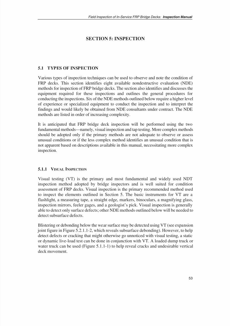
8/8/2019 Inspection of FRP Decks
http://slidepdf.com/reader/full/inspection-of-frp-decks 64/175
53
Field Inspection of In-Service FRP Bridge Decks: Inspection Manual
SECTION 5: INSPECTION
5.1 TYPES OF INSPECTION
Various types of inspection techniques can be used to observe and note the condition of FRP decks. This section identifies eight available nondestructive evaluation (NDE)methods for inspection of FRP bridge decks. The section also identifies and discusses theequipment required for these inspections and outlines the general procedures forconducting the inspections. Six of the NDE methods outlined below require a higher levelof experience or specialized equipment to conduct the inspection and to interpret thefindings and would likely be obtained from NDE consultants under contract. The NDE
methods are listed in order of increasing complexity.
It is anticipated that FRP bridge deck inspection will be performed using the twofundamental methods—namely, visual inspection and tap testing. More complex methodsshould be adopted only if the primary methods are not adequate to observe or assessunusual conditions or if the less complex method identifies an unusual condition that isnot apparent based on descriptions available in this manual, necessitating more complexinspection.
5.1.1 VISUAL
INSPECTION
Visual testing (VT) is the primary and most fundamental and widely used NDTinspection method adopted by bridge inspectors and is well suited for conditionassessment of FRP decks. Visual inspection is the primary recommended method usedto inspect the elements outlined in Section 5. The basic instruments for VT are aflashlight, a measuring tape, a straight edge, markers, binoculars, a magnifying glass,inspection mirrors, feeler gages, and a geologist’s pick. Visual inspection is generallyable to detect only surface defects; other NDE methods outlined below will be needed todetect subsurface defects.
Blistering or debonding below the wear surface may be detected using VT (see expansion joint figure in Figure 5.2.1.1-2, which reveals subsurface debonding). However, to helpdetect defects or cracking that might otherwise go unnoticed with visual testing, a staticor dynamic live-load test can be done in conjunction with VT. A loaded dump truck orwater truck can be used (Figure 5.1.1-1) to help reveal cracks and undesirable verticaldeck movement.
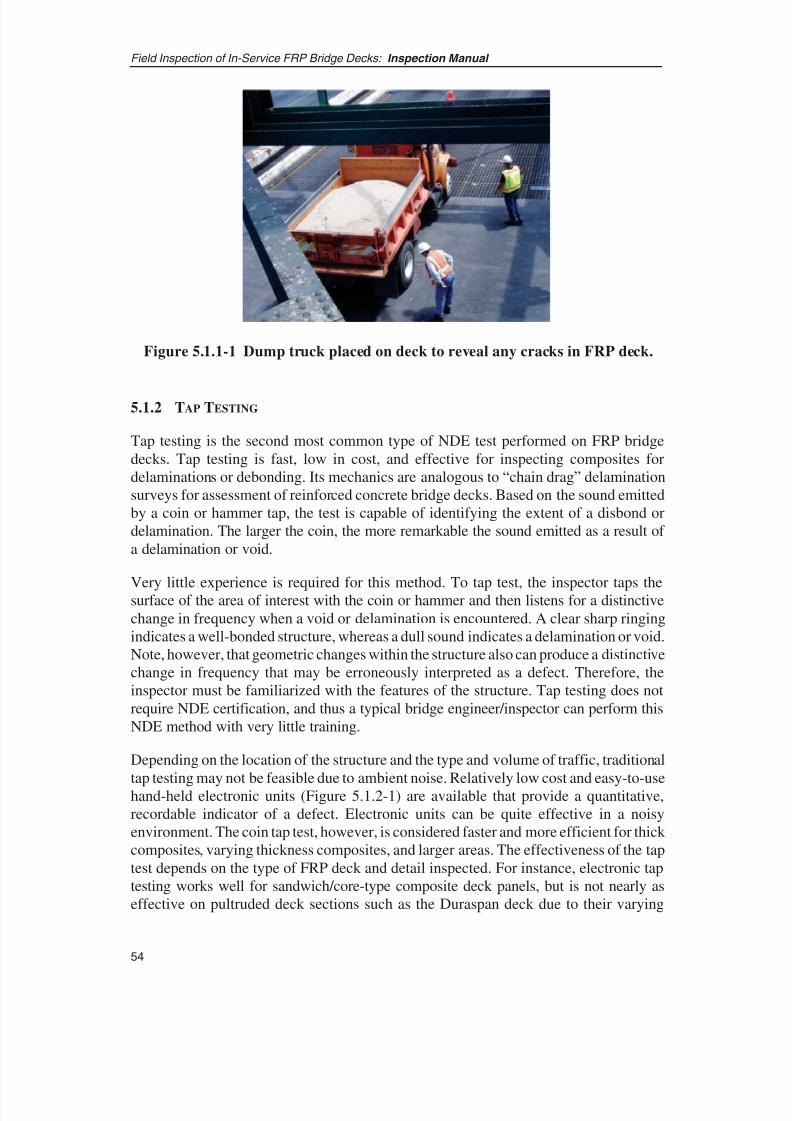
8/8/2019 Inspection of FRP Decks
http://slidepdf.com/reader/full/inspection-of-frp-decks 65/175
5.1.2 TAP TESTING
Tap testing is the second most common type of NDE test performed on FRP bridgedecks. Tap testing is fast, low in cost, and effective for inspecting composites fordelaminations or debonding. Its mechanics are analogous to “chain drag” delaminationsurveys for assessment of reinforced concrete bridge decks. Based on the sound emittedby a coin or hammer tap, the test is capable of identifying the extent of a disbond ordelamination. The larger the coin, the more remarkable the sound emitted as a result of a delamination or void.
Very little experience is required for this method. To tap test, the inspector taps thesurface of the area of interest with the coin or hammer and then listens for a distinctivechange in frequency when a void or delamination is encountered. A clear sharp ringingindicates a well-bonded structure, whereas a dull sound indicates a delamination or void.Note, however, that geometric changes within the structure also can produce a distinctivechange in frequency that may be erroneously interpreted as a defect. Therefore, theinspector must be familiarized with the features of the structure. Tap testing does notrequire NDE certification, and thus a typical bridge engineer/inspector can perform thisNDE method with very little training.
Depending on the location of the structure and the type and volume of traffic, traditional
tap testing may not be feasible due to ambient noise. Relatively low cost and easy-to-usehand-held electronic units (Figure 5.1.2-1) are available that provide a quantitative,recordable indicator of a defect. Electronic units can be quite effective in a noisyenvironment. The coin tap test, however, is considered faster and more efficient for thick composites, varying thickness composites, and larger areas. The effectiveness of the taptest depends on the type of FRP deck and detail inspected. For instance, electronic taptesting works well for sandwich/core-type composite deck panels, but is not nearly aseffective on pultruded deck sections such as the Duraspan deck due to their varying
Field Inspection of In-Service FRP Bridge Decks: Inspection Manual
54
Figure 5.1.1-1 Dump truck placed on deck to reveal any cracks in FRP deck.

8/8/2019 Inspection of FRP Decks
http://slidepdf.com/reader/full/inspection-of-frp-decks 66/175
55
Field Inspection of In-Service FRP Bridge Decks: Inspection Manual
internal geometry. Instruments required for tap testing are a flashlight, a measuring tape,a straight edge, markers, and a large coin or small hammer.
5.1.2-1 Electronic tap-tester unit.
5.1.3 THERMAL TESTING
Thermography uses an ambient or artificial heat source to heat a sample and a heat-sensing device such as an infrared camera to measure the temperature variation withinthe object of interest (Figure 5.1.3-1). Heat can be applied to the surface by natural
sunlight or by a pulsed light source, and then an infrared camera is used to measure thetemperature variation of the subject. Subsurface variations such as discontinuities orvoids in the material will cause slight changes in the wave infrared energy that radiatesfrom the surface of the part. These discontinuities in the material or emissivity differencescause gradients in the isothermal contours that are detectable by the infrared camera. Theadvantage of active thermography is that it is completely noncontacting and uses remoteheating and remote detection to make the measurements. However, thermographysystems can be quite expensive, ranging in cost from about $10,000 for lower-endsystems to $200,000 for sophisticated high-resolution image-processing systems.
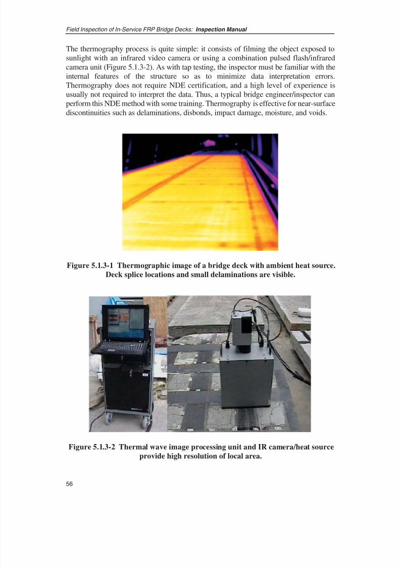
8/8/2019 Inspection of FRP Decks
http://slidepdf.com/reader/full/inspection-of-frp-decks 67/175
The thermography process is quite simple: it consists of filming the object exposed tosunlight with an infrared video camera or using a combination pulsed flash/infraredcamera unit (Figure 5.1.3-2). As with tap testing, the inspector must be familiar with theinternal features of the structure so as to minimize data interpretation errors.Thermography does not require NDE certification, and a high level of experience isusually not required to interpret the data. Thus, a typical bridge engineer/inspector canperform this NDE method with some training. Thermography is effective for near-surfacediscontinuities such as delaminations, disbonds, impact damage, moisture, and voids.
Field Inspection of In-Service FRP Bridge Decks: Inspection Manual
56
Figure 5.1.3-1 Thermographic image of a bridge deck with ambient heat source.
Deck splice locations and small delaminations are visible.
Figure 5.1.3-2 Thermal wave image processing unit and IR camera/heat source
provide high resolution of local area.

8/8/2019 Inspection of FRP Decks
http://slidepdf.com/reader/full/inspection-of-frp-decks 68/175
57
Field Inspection of In-Service FRP Bridge Decks: Inspection Manual
5.1.4 ACOUSTIC TESTING
In acoustic emission testing, an elastic wave is generated by the rapid release of energyfrom within a material. A structure under certain load levels produces acoustic sound,usually in the range between 20 KHz and 1 MHz. This sound generation is known as“acoustic emission” (AE). AE is simply the stress waves generated in the materials due
to deformation, crack initiation and growth, crack opening and closure, fiber breakage,and delamination in composite materials. The elastic waves come through the solid tothe surface where they can be recorded by one or more sensors/transducers. AE listensfor emissions from active defects and is very sensitive to defect activity when a structureis loaded.
The required equipment includes AE piezoelectric sensors, couplant, multi-channel dataacquisition hardware, and a fully integrated analysis and data acquisition software system(see Figure 5.1.4-1). The AE procedure consists of applying a couplant between thecomposite to be inspected and the sensors. Sensors are arrayed on the structure andconnected to data acquisition equipment to detect, measure, and record the structure’s
acoustic emissions.
Figure 5.1.4-1 Schematic of acoustic emission testing technique.
AE is a global monitoring method that can be used to isolate the location of problemareas in the structure. The global AE cannot determine the configuration or size of thedefect; however, it can be used to direct conventional NDE methods to the localizedproblem areas. AE requires a high level of skill and sophisticated equipment to conductthe test and interpret the data. The typical bridge maintenance engineer is unlikely tohave the expertise to conduct the test and evaluate the results; therefore, it is expected
8/8/2019 Inspection of FRP Decks
http://slidepdf.com/reader/full/inspection-of-frp-decks 69/175
that AE testing and the follow-up localized NDE testing will be contracted out. Typicaldiscontinuities detectable by AE include delaminations, debonding, and fiber breakage.AE can also be used to determine a flaw’s growth rate.
5.1.5 ULTRASONIC TESTING
Ultrasonic testing (UT) uses high-frequency sound in the range of 20 KHz to 25 MHz toevaluate internal volumetric condition of the material. This method involves applying acouplant to the area to be inspected and then scanning the area with a transducer (orprobe) attached to a UT machine. The couplant serves as a uniform medium between thescanning surface and the transducer to ensure transmission of sound waves. Variouscouplants are used between the specimen and the probe. The transducer/probe containsa piezoelectric crystal that transmits high-frequency sound into the specimen andreceives the returning or reflective signals for interpretation by displaying the signal inthe form of an “A” scan or a “C” scan. The A scan display is similar to an oscilloscope
display, giving the time of flight and reflection amplitude data. The C scan requiresadditional scanning equipment and displays a plan view of the detected defects. Typicaldiscontinuities that are detectable include delaminations, disbonds, resin variations,broken fibers, impact damage, moisture, cracks, voids, and subsurface defects.
Unlike visual inspection, tap testing, or thermography, UT demands a high level of expertise to properly conduct the test and interpret the data. The inspector should becertified by the American Society of Nondestructive Testing (ASNT). UT should not beused to randomly scan the FRP bridge deck. Whenever possible, a first pass visualinspection, tap test, or AE testing should be conducted prior to UT testing to isolate thelikely area of damage or defect. If visual inspection, tap testing, thermography, or AE
detects discontinuities or damage, a localized UT can be performed to furthercharacterize the location and size of the defect. Because the wear surface is rough anduneven and contains internal aggregate, using UT on the top deck surface is impracticalunless a very good calibration can be achieved. The angularity of the aggregate willreflect sound waves, resulting in false indications. UT can easily be used on the bottomand sides of an FRP deck, however.
An alternative UT method known as “laser-based ultrasound” testing is a promisingremote noncontact NDE inspection technique that combines the capabilities of optics andultrasonics to detect, locate, and determine the size of flaws in a material. This techniqueuses a pulsed laser to generate ultrasonic waves that propagate inside the material and
uses a second laser coupled to an optical interferometer to detect these waves. Theadvantage of laser-based UT is that it is a noncontact method that does not requirecouplant. No inexpensive portable laser-based UT units for large-scale field testing arereadily available, however, so this NDE method is not currently practical for typical FRPbridge deck inspection.
The cost of a basic UT unit varies depending on the unit’s sophistication (i.e., dataretrieval, output format, etc.), and whether any automated scanning is included. A basicultrasonic testing kit costs approximately $10,000.
Field Inspection of In-Service FRP Bridge Decks: Inspection Manual
58
8/8/2019 Inspection of FRP Decks
http://slidepdf.com/reader/full/inspection-of-frp-decks 70/175
59
Field Inspection of In-Service FRP Bridge Decks: Inspection Manual
5.1.6 RADIOGRAPHY
Radiography uses a penetrating radiation source such as X-rays or gamma rays andradiographic film to capture images of defects. Differential absorption of the penetratingradiation by the specimen will produce clearly discernible differences when recorded onradiographic film. Unlike ultrasonic testing, radiography cannot capture the volumetric
characteristics of defects; however, it does provide a higher resolution of the planaraspects of defects. Defect resolution depends somewhat on the orientation of the defectwith respect to the source and the film. Radiography requires access to both sides of thestructure, with the radiation source placed on one side source and the film placed on theother side. Typical discontinuities that are detectable include some delaminations andsome disbonds depending on the orientation, voids, resin variations, broken fibers,impact damage, and cracks. Radiography equipment can be hazardous if not handled orstored properly, and this method also requires a high level of skill both to conduct thetest and to evaluate the radiographs. It is recommended that individuals conducting thetest and evaluating the results be ASNT-certified.
An alternative to traditional radiography is the reverse-geometry digital X-ray. This is alow-level X-ray imaging system that eliminates the film sheet and uses television-typeraster scanning combined with computer-read digital data from a detector unit. Thismethod also requires access to both sides of the structure, with the source on one sideand the detector/receiver on the other. With reverse geometry X-ray imaging, alignmentof the X-ray source, object, and detector is not critical: three-dimensional images of thedefect can be constructed. This method is much faster due to the scanning capabilities,it is much safer, and it requires no processing of radiographic film. This method alsorequires a high level of experience and expensive, highly specialized equipment.
5.1.7 MODAL ANALYSIS
The modal parameters method is a health monitoring NDE method that uses changes inthe dynamic response of a structure to evaluate the structure’s condition. The givenstructure is instrumented with an array of accelerometers, and prescribed dynamic loadtests are performed to extract modal parameters with selected frequencies and modeshapes. Evaluating the structure requires modal parameters of the baseline structure (i.e.,as originally built) and of the existing structure (i.e., in its current condition). In mostcases, baseline parameters of a structure do not exist; however, the baseline modalparameters can be approximated from dynamic testing of the existing structure and from
developing a numerical (finite element) model of the as-built condition.
This method requires capital investment for sensors and data acquisition equipment, staff training, and a relatively high skill level for the setup and data reduction andinterpretation. Hence, the modal parameters method shall be used only if othertechniques are unable to address concerns about hidden damages and overall structuralperformance of the FRP decks and its variation in time.
8/8/2019 Inspection of FRP Decks
http://slidepdf.com/reader/full/inspection-of-frp-decks 71/175
A stiffness sensitivity analysis is performed to evaluate stiffness changes in the structureby determining the damage location index. The damage index identifies local potentialdamage of structural members. Damage severity is then estimated for each predicteddamage location. A current research project of the California DOT (Caltrans) and theUniversity of California at San Diego is investigating a fracture mechanics–basedapproach to the modal parameters method to estimate the severity of the damage and toevaluate the impact of damage on the structure. This testing method requires a very highlevel of experience at the research or experimental level. However, the modal-parametersmethod is a viable option to evaluate whether the structure has undergone a change instiffness.
Caltrans has successfully used the modal-parameters method for experimental healthmonitoring and NDE on a few bridges, two of which were strengthened by FRPcomposites and one of which is a hybrid design consisting of carbon-fiber reinforcedplastic (CFRP) girders and a glass-fiber reinforced plastic (GFRP) bridge deck.
5.1.8 LOAD TESTING
In this nondestructive field performance evaluation test, a bridge is instrumented withsensors such as strain gages, accelerometers, and displacement sensors and thensubjected to a known live load with a specific loading pattern. The instrumentation canserve the dual purposes of capturing the measured response of the structure during loadtests and helping to monitor the long-term structural health of the bridge. Since a largeproportion of the nation’s FRP bridge decks were placed in service on a demonstrationand technology transfer basis, a number of these new decks were instrumented and loadtested with this method before the bridges were opened for service. Additionally, the load
tests have been repeated at periodic intervals to assess any changes in deck response withtime. This method is reserved for situations in which fundamental inspection techniquesproduce uncertain results.
This method requires an investment in sensors and data acquisition equipment and arelatively high skill level for the setup and data reduction and interpretation. Hence, load-testing method should be used only if other techniques are unable to address concernsabout hidden damages and overall structural performance of the FRP decks and itsvariation in time.
Caltrans performed elaborate load testing on the Kings Stormwater Bridge after a routine
field inspection that used the tap-test method identified possible separations between theCFRP-filament-wound girders and the concrete. Load tests indicated that the overallresponse of the bridge had not degraded and that the performance was about the same aswhen the bridge was first opened to traffic. Load testing was carried out with a widerscope and longer duration on the Schuyler Heim Bridge deck replacement project. Theidea is that any damage at Category 1 or 2 affects the FRP deck panel stiffness locallyand the superstructure more globally and therefore would influence the response of thebridge to dead and live loading.
Field Inspection of In-Service FRP Bridge Decks: Inspection Manual
60

8/8/2019 Inspection of FRP Decks
http://slidepdf.com/reader/full/inspection-of-frp-decks 72/175
61
Field Inspection of In-Service FRP Bridge Decks: Inspection Manual
The scope of load testing can vary depending on the purpose it’s meant to serve and theresources available. For the purpose of inspection—that is, to verify bridge performanceand detect potential damage for condition rating—limited-scope proof testing may bereasonable and manageable within the scope of a periodic inspection program. Thefollowing procedure is proposed:
• Timing: Perform load testing shortly after completion of bridge construction andat intervals that coincide with field inspection. Periodic testing should beperformed under similar weather and environmental conditions.
• Test load: Use a truck heavy enough to generate considerable deflection in thedeck. Truck weight of about the design load is recommended.
• Test configuration: Apply static loading by moving the truck along at least twosymmetric lanes and stopping it at predefined locations along the bridge deck.Quarter points and mid-span are recommended, depending on the span length.
• Test procedure: Place the truck at specified locations and keep it stopped therefor a specified time duration (e.g., 1 ⁄ 2 h). While the truck is stopped, inspect thebridge for signs of damage that could become apparent under load. At the end of stop time, collect deflection data and then move the truck to the next position.Repeat the procedure for all positions.
• Instrumentation and data collection: Measure deck span deflection at specifiedlocations along and transverse to the bridge deck. It is recommended thatdeflection be measured at quarter points and mid-span along the bridge and atthree points transversely at each location. Measurements can be taken usingelectronic displacement transducers, mechanical dial gages, or hand rulers and
taut string, depending on the deflection amplitude, the recommended precision,accessibility, and span length. Measure deflection at the end of each stop time andagain 1 ⁄ 2 h after the load is completely removed from the deck.
• Criteria: Bridge deflection under design or near-design load shall be less thanthe allowable deflection recommended by AASHTO. Deflection can also becompared with the designer’s predicted deflection. Deflections shall be recoveredalmost entirely (e.g., within ± 5%) a specified time after unloading. Comparedeflections at each period with those at initial and subsequent measurements, andreport any difference. Significant differences indicate damage, and the changepattern—combined with results of visual inspection during load testing—may
identify the approximate location.
Load testing can provide more complex data when performed by trained specialists usingmore sophisticated technology. Bridge owners and inspectors are referred to NCHRP
Research Results Digest 234: Manual for Bridge Rating through Load Testing for moreinformation.

8/8/2019 Inspection of FRP Decks
http://slidepdf.com/reader/full/inspection-of-frp-decks 73/175
5.1.9 COMPARISON OF METHODS
Potential inspection methods for FRP decks have been identified from aerospacetechnology, defense technology, shipbuilding, pressure vessels, and bridges. Detaileddescriptions and discussions on the inspection methods are presented in the precedingsections. Methods such as visual inspection, tap testing, and ultrasonic testing are similar
to those currently used in bridge inspection. More complicated methods such as acoustic,radiography, thermography, and so forth are seldom used in current bridge inspectionprograms. In Table 5.1.9-1, the various inspection methods are correlated to the types of defects they can help detect.
Field Inspection of In-Service FRP Bridge Decks: Inspection Manual
62
*Table based on Report Reference 19, see p. 158 for reference.
Technique
Visual X X X X
Mechanical Impedance (Tap Test) X X X X X
Thermal X X X
Ultrasonic X X X X
Acoustic Emission X X X
Ra
diogra
phic X X X XLaser Shearography and Other X X X X
F e a t u r e s a n
d
A n o m a l i e s
F o r e i g n M a t t
e r
C o r e o r I n t e r n a l
E l e m e n t s
E x t e r n a l E l e m e
n t s
I m p a c t D a m a
g e
C r a c k s
D e l a m i n a t i o n
s
D i s b o n d s
Table 5.1.9-1 Inspection Method Applicability for Specific Defects and Deck
Element Features*
Highway agencies can assume that techniques other than visual and tap testing might bewarranted under certain circumstances. These can be provided by consultants andinspection firms. When used, inspection costs for services proffered by consultants willbe different than those of a highway agency inspection unit’s routine visual inspectionor tap testing–based protocol. For reference purposes, the following cost data for fieldtesting and inspection services were gathered and are provided, based on the researchteam’s experience. These can be used to estimate comparative costs:
• Consultant Inspection Staff Hourly Fee (Technician/Inspector): $50 to $100hourly depending on experience, including test equipment.
• Consultant Inspection Staff Hourly Fee (Engineer/Team Leader): $90 to $150hourly depending on experience, including test equipment.
• It must be taken into account that radiography, X-ray, infrared, and load-testmethods require specialized equipment and particular safety precautions.

8/8/2019 Inspection of FRP Decks
http://slidepdf.com/reader/full/inspection-of-frp-decks 74/175
63
Field Inspection of In-Service FRP Bridge Decks: Inspection Manual
While the hourly rates above for inspection labor are representative for inspectionstaff skilled in these methods, additional daily fees ranging from a few hundreddollars to $1,000 or more may accrue for procuring equipment or support forthese more complex, capital equipment–reliant inspection methods.
The visual method is by far the simplest and most important technique for inspecting
FRP decks. Even in the aerospace and defense industries, inspectors rely on the visualtechnique for detecting in-service problems. It allows the inspector to rapidly detect grossimperfections or defects such as cracks, delamination, or impact damage. Visualinspection often can aid in detecting other imperfections such as porous adhesive fillets,lack of filleting, lack of adhesive, edge voids, discoloration, deformation, and otherimperfections. To a trained inspector, the visual technique provides immediate clueswhile helping to identify areas that need more detailed examination. This techniquerequires operator interpretation, so inspectors should be trained to know what they arelooking for and what any variation might mean to the strength and reliability of thecomponent. The visual method has two drawbacks, however: (1) it does not lend itself well to quantifying the extent of damage and (2) it cannot be used to inspect componentsthat are not directly visible.
Tap testing is another excellent and easy-to-use method for inspecting FRP decks. In thetap test, the inspector listens for any change in sounds emitted while tapping FRPsurfaces. This method works best for inspecting sandwich panels with thin facesheets,but it can also be used on pultruded sections although there it is less effective in detectingdelaminations or debonds. Still, most common problems on FRP decks can be identifiedusing the tap-test method in conjunction with the visual technique.
Neither of these techniques requires any specialized equipment, and, with some training,both are easy to incorporate into a bridge owner’s inspection program. Other techniques
listed above are much more complex, expensive, and time-consuming to use. Theyrequire special expertise both to conduct the tests and interpret the results. Except forthermography, most of the more specialized methods are useful only for inspecting smallareas. Therefore, these methods are best reserved for detailed assessment of potentiallydamaged or defective areas once they have been identified by either visual inspection ortap testing.
Of the various advanced methods, thermography and UT appear to be most practical fora bridge owner’s inspection program. Already familiar with UT equipment and technique,bridge engineers and inspectors can more easily adapt this method for use on FRP decks.Thermography is relatively easy to use, requires no very expensive equipment, and
provides output that can be visually analyzed, so it too could readily be adopted into anowner’s inspection program. The other techniques, such as radiography and shearography(an interferometric system that uses an expanded beam of laser light reflected off thespecimen) are more costly, involve expensive specialized equipment, and requireconsiderable training to operate the equipment and interpret the results. Hence these othertechniques, although useful and applicable, seem less likely to be adopted for regular
8/8/2019 Inspection of FRP Decks
http://slidepdf.com/reader/full/inspection-of-frp-decks 75/175
bridge inspection programs. Bridge owners are more likely to contract out for theseservices when needed.
The modal-parameters method and load-testing method both investigate change instructural dynamic and static performance, respectively. When compared with previousresults or baseline results, these techniques can identify changes in response and correlate
as much as possible to the occurrence and accumulation of damage in the FRP deck.They can identify whether damage has occurred and sometimes determine the locationand intensity of the damage. These techniques can be used on newly constructed decksas a means of health monitoring or to determine the extent of damage or its effects on thestructural response parameters after signs of distress and damage have been observed.These techniques require an investment for sensors and data acquisition equipment, anda relatively high skill level for the setup and data reduction and interpretation. They offera medium level of accuracy and reliability. Hence, modal parameters and load-testingmethods should be used only if other techniques are unable to address concerns abouthidden damages and overall structural performance of the FRP decks and its variation intime.
5.1.10 INSPECTOR QUALIFICATIONS, SITE SAFETY, AND OTHER ISSUES
The inspector and team leader qualifications should be as given in the Code of Federal
Regulations, the latest edition of the AASHTO Manual for Condition Evaluation of
Bridges, or as stipulated by the state DOT. Inspectors also should have additionalqualifications and experience to identify the need for advanced inspection methods suchas acoustic, ultrasonic, radiographic, and so forth and to interpret the resulting data. It isrecognized that specialist nondestructive testing (NDT) engineers, employed by highway
organizations or consultants, may be called upon to perform these inspections.
Traffic control, access, safety, equipment, and other site-related issues should be plannedand managed by the inspection team leader in accordance with the U.S. Department of Labor’s Occupational Safety and Health Organization, the Manual of Uniform Traffic
Control Devices, and the AASHTO Manual for Condition Evaluation of Bridges. Anyother standards or requirements stipulated by state or local regulatory authorities shouldalso be followed when addressing issues related to the fieldwork.
5.2 INSPECTION OF FRP DECKS
Just as Section 4 divided the important details of FRP bridge decks into two maincategories, the inspection of these details is discussed in the same two categories, namely
1. External details: All the components and appurtenances on or near FRP decks thatmight be critical directly or indirectly for FRP bridge safety. This categoryincludes connections, joints, curbs, sidewalks, railings, and other such componentsof a bridge.
Field Inspection of In-Service FRP Bridge Decks: Inspection Manual
64
8/8/2019 Inspection of FRP Decks
http://slidepdf.com/reader/full/inspection-of-frp-decks 76/175
65
Field Inspection of In-Service FRP Bridge Decks: Inspection Manual
2. Internal details: The FRP deck section itself, including the facesheets, cores, webcomponents, and panel edges.
The inspection of items in both categories is discussed in detail in the following sections.
5.2.1 INSPECTION OF EXTERNAL DETAILS
Guidance on inspection of details and locations on external components of FRP deck isprovided in the following sections. These details and locations should be inspected andevaluated during any inspection of FRP decks because as they are likely the first toexhibit signs of distress.
5.2.1.1 Panel-to-Panel Connections
The panel-to-panel connection should be thoroughly investigated during each inspection.
As a minimum, the following should be checked during the inspection:
• Look for signs of reflective cracking and wear of field-applied joint splicematerial at the deck panel splice joints. Reflective cracking or oozing of jointmaterial may indicate an improper fit or movement between adjoining panels atthe joint (Figure 5.2.1.1-1).
• Look for signs of delamination or spalling of wearing surface in the vicinity of the joint (Figure 5.2.1.1-2).
• Check for signs of buckling, misalignment, and differential vertical or horizontalmovement at the expansion joints by observing the joints at the top of the deck
(Figures 5.2.1.1-3 and 5.2.1.1-4).
• Check for signs of opening or separation of joints (Figure 5.2.1.1-5).
• On decks where the joint is not covered by FRP laminates, use feeler gages onthe underside of the deck to record the gap between the deck panels. An excessivegap should be monitored and flagged for maintenance action.
• Use feeler gages to check for any delamination of the adhered shear splice platesat butt joints.
• Use a small hammer to conduct tap tests in the vicinity of the joint. Any hollowsound should be further investigated using more advanced inspection methods toascertain its extent and cause.

8/8/2019 Inspection of FRP Decks
http://slidepdf.com/reader/full/inspection-of-frp-decks 77/175
Field Inspection of In-Service FRP Bridge Decks: Inspection Manual
66
Figure 5.2.1.1-1 Reflective cracking and oozed material at FRP deck-to-deck joints.
Figure 5.2.1.1-2 Debonding at joint and below wear surface.
Figure 5.2.1.1-3 Misalignment of deck-to-deck joint.
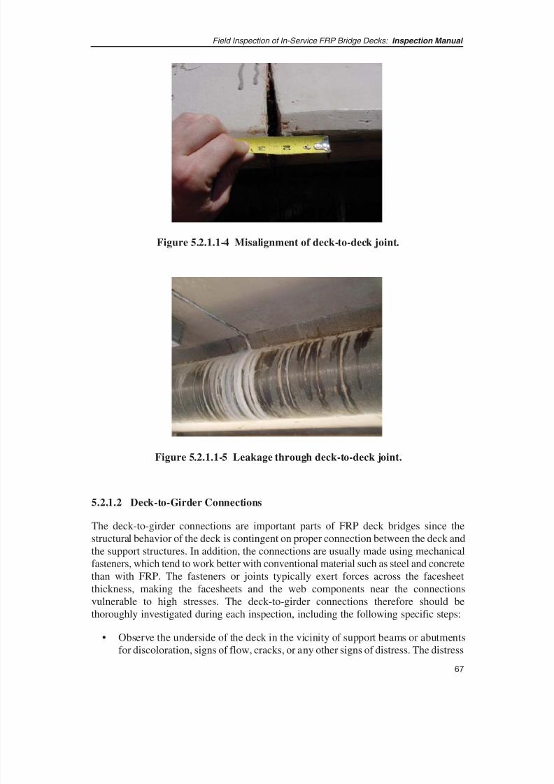
8/8/2019 Inspection of FRP Decks
http://slidepdf.com/reader/full/inspection-of-frp-decks 78/175
5.2.1.2 Deck-to-Girder Connections
The deck-to-girder connections are important parts of FRP deck bridges since thestructural behavior of the deck is contingent on proper connection between the deck and
the support structures. In addition, the connections are usually made using mechanicalfasteners, which tend to work better with conventional material such as steel and concretethan with FRP. The fasteners or joints typically exert forces across the facesheetthickness, making the facesheets and the web components near the connectionsvulnerable to high stresses. The deck-to-girder connections therefore should bethoroughly investigated during each inspection, including the following specific steps:
• Observe the underside of the deck in the vicinity of support beams or abutmentsfor discoloration, signs of flow, cracks, or any other signs of distress. The distress
67
Field Inspection of In-Service FRP Bridge Decks: Inspection Manual
Figure 5.2.1.1-4 Misalignment of deck-to-deck joint.
Figure 5.2.1.1-5 Leakage through deck-to-deck joint.

8/8/2019 Inspection of FRP Decks
http://slidepdf.com/reader/full/inspection-of-frp-decks 79/175
should be marked and monitored visually or with measuring instruments todetermine whether it is active in response to traffic or other live-load application.
• On the underside of the deck, look for any separation between the deck and thehaunch or other supporting superstructure component. Feeler gages should be usedto measure the gap, and the gaps should be monitored. Gaps between the stringers
and the deck could indicate warping or uplift of the deck. Further investigate anysuch signs to determine the cause of the uplift or warping. See Figure 5.2.1.2-1.
• Observe and note any cracking of haunch grout material.
• Examine neoprene pads or concrete haunches at deck supports to ensure the FRPdeck is bearing fully on the stringer. Shim any gaps after fully evaluating thecause of the uplift or gap.
• On the underside of the deck, perform tap tests on the deck in the vicinity of thesupports. Mark any hollow-sounding areas for monitoring. If the hollow areas are
extensive, investigate them further using advanced inspection techniques such asthermal imaging or acoustic or ultrasonic testing.
• Check clip-type connections for soundness and tightness. Check the bolts on theclips to ensure that they are tight. Tap the clips with a small hammer to ensuretheir snugness. See Figure 5.2.1.2-2.
• If connectors such as Nelson studs or clip bolts are not accessible for visualexamination, static or dynamic live-load testing could assist in determining theproper operation of these connectors.
• Visually examine the FRP deck and the steel stringers for scratches, abrasion orother signs of movement at the clip connections. Check for any cracks in the FRPdeck area bearing against the bolt for the clip connection.
• On the top of the deck, watch for any cracks in the wearing surface, or deformationor unevenness of the deck at the stringer or approach supports. This may be a signof differential movement between the deck and the supports. See Figure 5.2.1.2-3.
Field Inspection of In-Service FRP Bridge Decks: Inspection Manual
68

8/8/2019 Inspection of FRP Decks
http://slidepdf.com/reader/full/inspection-of-frp-decks 80/175
69
Field Inspection of In-Service FRP Bridge Decks: Inspection Manual
Figure 5.2.1.2-1 FRP deck and connection studs.
Figure 5.2.1.2-2 Clip type connection.
Figure 5.2.1.2-3 Crack in haunch.
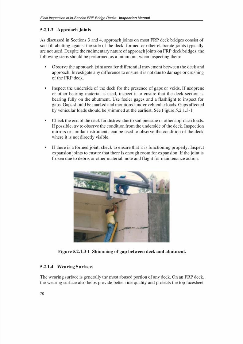
8/8/2019 Inspection of FRP Decks
http://slidepdf.com/reader/full/inspection-of-frp-decks 81/175
5.2.1.3 Approach Joints
As discussed in Sections 3 and 4, approach joints on most FRP deck bridges consist of soil fill abutting against the side of the deck; formed or other elaborate joints typicallyare not used. Despite the rudimentary nature of approach joints on FRP deck bridges, thefollowing steps should be performed as a minimum, when inspecting them:
• Observe the approach joint area for differential movement between the deck andapproach. Investigate any difference to ensure it is not due to damage or crushingof the FRP deck.
• Inspect the underside of the deck for the presence of gaps or voids. If neopreneor other bearing material is used, inspect it to ensure that the deck section isbearing fully on the abutment. Use feeler gages and a flashlight to inspect forgaps. Gaps should be marked and monitored under vehicular loads. Gaps affectedby vehicular loads should be shimmed at the earliest. See Figure 5.2.1.3-1.
• Check the end of the deck for distress due to soil pressure or other approach loads.If possible, try to observe the condition from the underside of the deck. Inspectionmirrors or similar instruments can be used to observe the condition of the deck where it is not directly visible.
• If there is a formed joint, check to ensure that it is functioning properly. Inspectexpansion joints to ensure that there is enough room for expansion. If the joint isfrozen due to debris or other material, note and flag it for maintenance action.
Field Inspection of In-Service FRP Bridge Decks: Inspection Manual
70
Figure 5.2.1.3-1 Shimming of gap between deck and abutment.
5.2.1.4 Wearing Surfaces
The wearing surface is generally the most abused portion of any deck. On an FRP deck,the wearing surface also helps provide better ride quality and protects the top facesheet

8/8/2019 Inspection of FRP Decks
http://slidepdf.com/reader/full/inspection-of-frp-decks 82/175
71
Field Inspection of In-Service FRP Bridge Decks: Inspection Manual
of the deck. The wearing surface inspection, at a minimum, should include the followingactivities:
• Chain drag is an effective way to locate distressed areas of the wearing surface.To an experienced inspector, the difference in the sound of chain drag couldsignal delamination location, extent, and whether the delamination is between the
wearing surface and the top facesheet or between the facesheets and webs. Oncedelamination is identified, more detailed investigation via tap testing orthermography could help determine the nature of the delamination.
• Check for signs of blistering/debonding of the wearing surface. Although it canbe difficult, try to determine whether the debonding or delamination is betweenfacesheet and wearing surface or within the facesheet itself. Use a well-calibratedtap tester or the UT method to help identify the location of delamination. Figures5.2.1.4-1 and 5.2.1.4-2 show an example of delamination and failure of the wearsurface.
• Check for buckling of the wear surface. Visual signs as well as the tap test canhelp identify buckling. See Figure 5.2.1.4-3.
• Carefully observe areas over joints and around other openings in the deck suchas scuppers. These areas are susceptible to cracking due either to differentialmovement between adjoining sections or to stress concentration at corners of openings.
Figure 5.2.1.4-1 Delamination/failure of wear surface on an FRP deck.
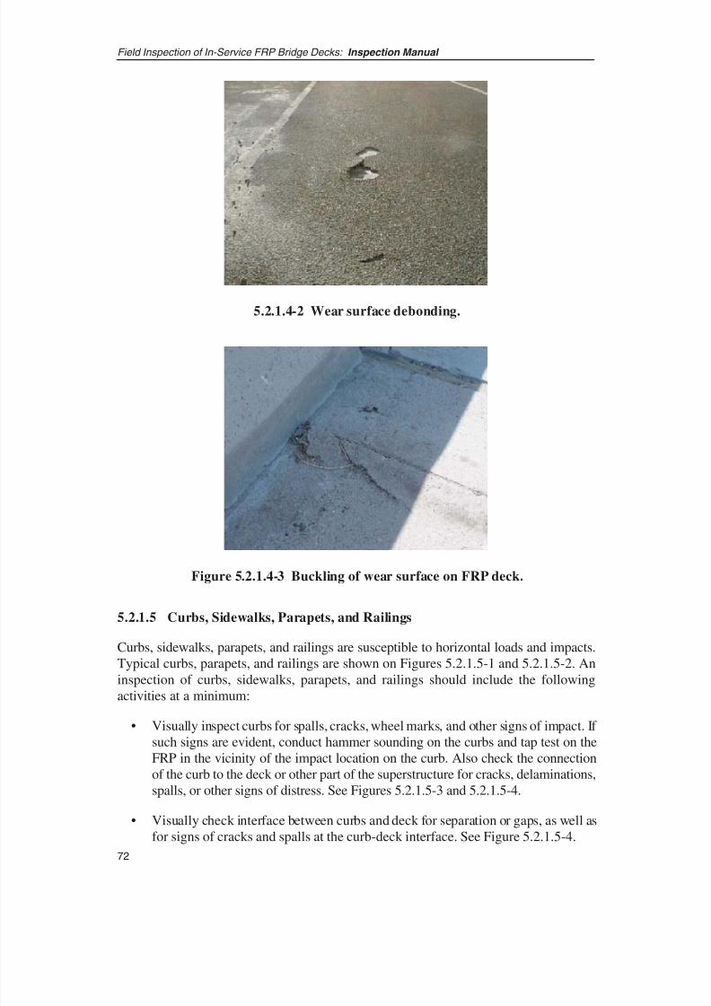
8/8/2019 Inspection of FRP Decks
http://slidepdf.com/reader/full/inspection-of-frp-decks 83/175
5.2.1.5 Curbs, Sidewalks, Parapets, and Railings
Curbs, sidewalks, parapets, and railings are susceptible to horizontal loads and impacts.Typical curbs, parapets, and railings are shown on Figures 5.2.1.5-1 and 5.2.1.5-2. Aninspection of curbs, sidewalks, parapets, and railings should include the followingactivities at a minimum:
• Visually inspect curbs for spalls, cracks, wheel marks, and other signs of impact. If such signs are evident, conduct hammer sounding on the curbs and tap test on theFRP in the vicinity of the impact location on the curb. Also check the connectionof the curb to the deck or other part of the superstructure for cracks, delaminations,spalls, or other signs of distress. See Figures 5.2.1.5-3 and 5.2.1.5-4.
• Visually check interface between curbs and deck for separation or gaps, as well asfor signs of cracks and spalls at the curb-deck interface. See Figure 5.2.1.5-4.
Field Inspection of In-Service FRP Bridge Decks: Inspection Manual
72
5.2.1.4-2 Wear surface debonding.
Figure 5.2.1.4-3 Buckling of wear surface on FRP deck.
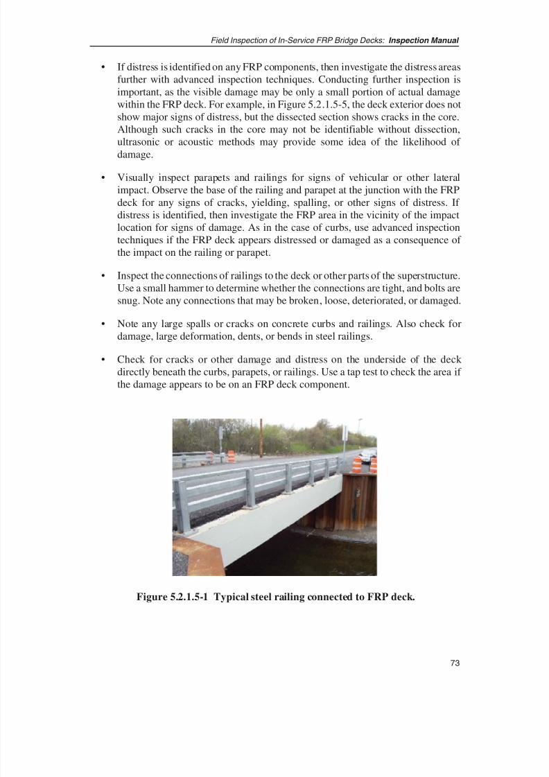
8/8/2019 Inspection of FRP Decks
http://slidepdf.com/reader/full/inspection-of-frp-decks 84/175
73
Field Inspection of In-Service FRP Bridge Decks: Inspection Manual
• If distress is identified on any FRP components, then investigate the distress areasfurther with advanced inspection techniques. Conducting further inspection isimportant, as the visible damage may be only a small portion of actual damagewithin the FRP deck. For example, in Figure 5.2.1.5-5, the deck exterior does notshow major signs of distress, but the dissected section shows cracks in the core.Although such cracks in the core may not be identifiable without dissection,ultrasonic or acoustic methods may provide some idea of the likelihood of damage.
• Visually inspect parapets and railings for signs of vehicular or other lateralimpact. Observe the base of the railing and parapet at the junction with the FRPdeck for any signs of cracks, yielding, spalling, or other signs of distress. If distress is identified, then investigate the FRP area in the vicinity of the impactlocation for signs of damage. As in the case of curbs, use advanced inspectiontechniques if the FRP deck appears distressed or damaged as a consequence of the impact on the railing or parapet.
• Inspect the connections of railings to the deck or other parts of the superstructure.Use a small hammer to determine whether the connections are tight, and bolts aresnug. Note any connections that may be broken, loose, deteriorated, or damaged.
• Note any large spalls or cracks on concrete curbs and railings. Also check fordamage, large deformation, dents, or bends in steel railings.
• Check for cracks or other damage and distress on the underside of the deck directly beneath the curbs, parapets, or railings. Use a tap test to check the area if the damage appears to be on an FRP deck component.
Figure 5.2.1.5-1 Typical steel railing connected to FRP deck.
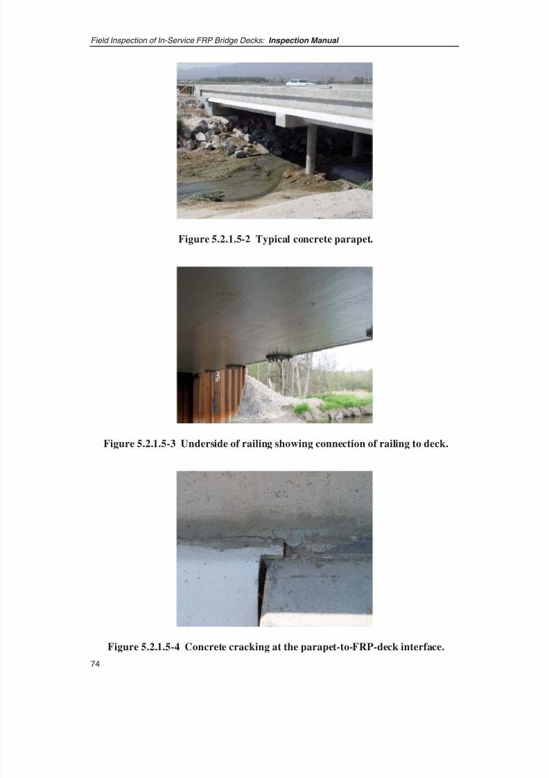
8/8/2019 Inspection of FRP Decks
http://slidepdf.com/reader/full/inspection-of-frp-decks 85/175
Field Inspection of In-Service FRP Bridge Decks: Inspection Manual
74
Figure 5.2.1.5-2 Typical concrete parapet.
Figure 5.2.1.5-3 Underside of railing showing connection of railing to deck.
Figure 5.2.1.5-4 Concrete cracking at the parapet-to-FRP-deck interface.

8/8/2019 Inspection of FRP Decks
http://slidepdf.com/reader/full/inspection-of-frp-decks 86/175
5.2.2 INSPECTION OF INTERNAL DETAILS
As discussed in Section 4.3, FRP decks are largely sandwich panels composed of thefollowing sub-elements:
• Top facesheet external laminate,
• Center core section and its components,
• Bottom facesheet external laminate,
• Panel-to-panel connections,
• Secondary components such as closeouts, and
• Penetrations and holes.
Visual access to all of these sub-elements is generally restricted because of the boxconstruction of decks. Assessment of the proper functional behavior of these deck components must, therefore, be made indirectly through observation and inspection of the observable surfaces. This reduces the domain of the inspection to the following FRPdeck features:
• Surface of the top facesheet,
• Edges of the decks,
• Deck-to-deck connection, and
• Surface of the bottom facesheet.
75
Field Inspection of In-Service FRP Bridge Decks: Inspection Manual
Figure 5.2.1.5-5 Cracks in the web of FRP deck.

8/8/2019 Inspection of FRP Decks
http://slidepdf.com/reader/full/inspection-of-frp-decks 87/175
What is important are the appearance and performance of the deck system in service.Aside from the wear surface, visual indicators of problems or potential problems maynot appear immediately after installation, but arise over time. Even FRP decks withconsiderable internal damage can remain quite robust overall, with problems occurringonly in the vicinity of the damage. The following are the symptoms most likely to beencountered on an FRP deck system and probable causes that might drive the decisionto pursue the inspection further.
5.2.2.1 Facesheets
External laminates or facesheets are the deck elements most likely to be directly affectedby vehicular and other loads. The top facesheet is the most vulnerable componentbecause it directly bears all vehicular loads and also is under compressive stress. Inspectfacesheets thoroughly through visual and tap testing. The wearing surface makes itdifficult to inspect the top surface of facesheets, but make every attempt to inspect thefacesheet indirectly as discussed below:
• The condition of the wear surface is also an important aspect of inspectionbecause many deck performance problems are reflected on the wear surface.Even when wear surface adhesion to the deck surface is good, stress cracking maystill occur from excessive movement or strain within the facesheet. Decks madewith bonded pultruded sections can exhibit line cracks at the factory bondline,signaling excessive motion of the adhesive joints as shown in Figure 5.2.2.1-1.
• Look for local bubbles in the facesheet. Decks are typically flat panels, and anyunusual bubbling, rise, or undulation should be investigated further. Use the taptest to determine the extent of the bubble. On top surface, determining whetherthe bubble is in the wear surface or in the deck laminate will generally be difficult.
Advanced inspection techniques such as thermography, UT, or a well-calibratedtap test can help determine whether the bubble is in the facesheet. An example of this anomaly is shown in Figure 5.2.2.1-2.
• Look for signs of surface deterioration from wear and tear and environmentalexposure. Such damage would generally be as apparent from wear marks, fiberexposure, discoloration, stretch marks, and so forth.
• Look for impact damage on the facesheet. An extreme example is shown inFigure 5.2.2.1-3 where punch-through has resulted from impact.
• Look for damage from acts of vandalism such as that shown in Figure 5.2.2.1-4where vandals attempted to burn the FRP material.
• Persistent moisture residue around an area could indicate the presence of voids,delamination, or holes as shown in Figure 5.2.2.1-5.
• Delamination is typically classified as a separation of plies within the facesheetlaminate, but such separation can also occur at the boundary layer between
Field Inspection of In-Service FRP Bridge Decks: Inspection Manual
76
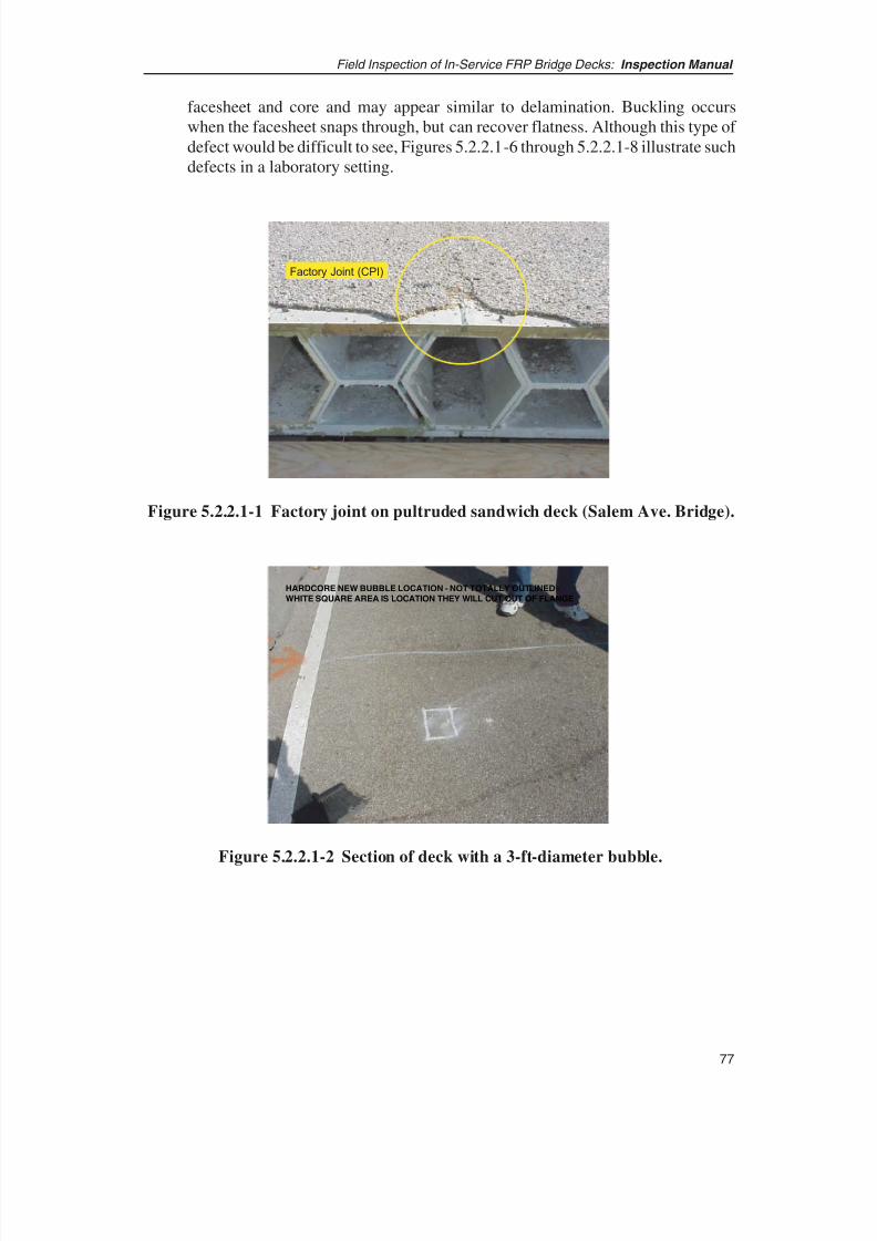
8/8/2019 Inspection of FRP Decks
http://slidepdf.com/reader/full/inspection-of-frp-decks 88/175
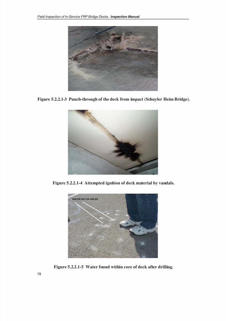
8/8/2019 Inspection of FRP Decks
http://slidepdf.com/reader/full/inspection-of-frp-decks 89/175
Field Inspection of In-Service FRP Bridge Decks: Inspection Manual
78
WATER OUT OF HOLESWATER OUT OF HOLES
Figure 5.2.2.1-3 Punch-through of the deck from impact (Schuyler Heim Bridge).
Figure 5.2.2.1-4 Attempted ignition of deck material by vandals.
Figure 5.2.2.1-5 Water found within core of deck after drilling.
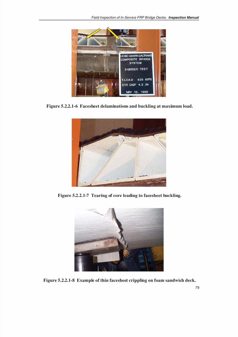
8/8/2019 Inspection of FRP Decks
http://slidepdf.com/reader/full/inspection-of-frp-decks 90/175

8/8/2019 Inspection of FRP Decks
http://slidepdf.com/reader/full/inspection-of-frp-decks 91/175
5.2.2.2 Sandwich Cores
Visual inspection of sandwich cores and web components is unlikely since they aretypically sealed within the facesheets. Inspecting these components therefore entails theuse of advanced techniques such as radiography or indirect methods such as impulseresponse and load testing. Furthermore, as discussed in the previous section, any failure
of the core or web would show signs of distress in the facesheets and wearing surfacesbefore the defect would seriously threaten deck safety. Hence, the most practical way toinspect sandwich cores is to indirectly infer the health of the core from inspection of facesheets and other visible deck components. To indicate how distress and possiblefailure of a sandwich core component might look, examples of laboratory testing of FRPdecks are illustrated in Figures 5.2.2.2-1 and 5.2.2.2-2.
Field Inspection of In-Service FRP Bridge Decks: Inspection Manual
80
Figure 5.2.2.2-1 Foam sandwich deck failure under line load.
Figure 5.2.2.2-2 Example of web failure and debonding of thick
facesheet from core.
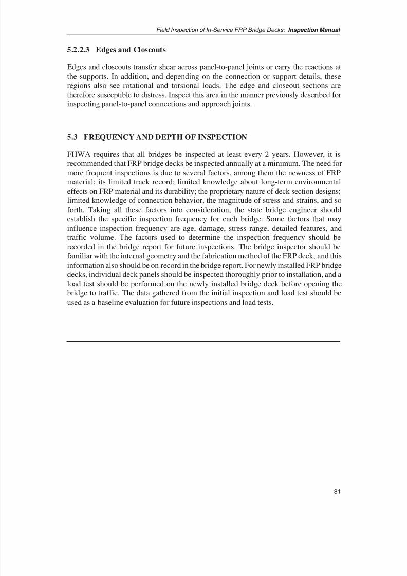
8/8/2019 Inspection of FRP Decks
http://slidepdf.com/reader/full/inspection-of-frp-decks 92/175
81
Field Inspection of In-Service FRP Bridge Decks: Inspection Manual
5.2.2.3 Edges and Closeouts
Edges and closeouts transfer shear across panel-to-panel joints or carry the reactions atthe supports. In addition, and depending on the connection or support details, theseregions also see rotational and torsional loads. The edge and closeout sections aretherefore susceptible to distress. Inspect this area in the manner previously described for
inspecting panel-to-panel connections and approach joints.
5.3 FREQUENCY AND DEPTH OF INSPECTION
FHWA requires that all bridges be inspected at least every 2 years. However, it isrecommended that FRP bridge decks be inspected annually at a minimum. The need formore frequent inspections is due to several factors, among them the newness of FRPmaterial; its limited track record; limited knowledge about long-term environmentaleffects on FRP material and its durability; the proprietary nature of deck section designs;
limited knowledge of connection behavior, the magnitude of stress and strains, and soforth. Taking all these factors into consideration, the state bridge engineer shouldestablish the specific inspection frequency for each bridge. Some factors that mayinfluence inspection frequency are age, damage, stress range, detailed features, andtraffic volume. The factors used to determine the inspection frequency should berecorded in the bridge report for future inspections. The bridge inspector should befamiliar with the internal geometry and the fabrication method of the FRP deck, and thisinformation also should be on record in the bridge report. For newly installed FRP bridgedecks, individual deck panels should be inspected thoroughly prior to installation, and aload test should be performed on the newly installed bridge deck before opening thebridge to traffic. The data gathered from the initial inspection and load test should be
used as a baseline evaluation for future inspections and load tests.

8/8/2019 Inspection of FRP Decks
http://slidepdf.com/reader/full/inspection-of-frp-decks 93/175
SECTION 6: RECORDKEEPING
This section elaborates on a uniform method of annotating and describing damage andfindings of FRP deck inspection.
6.1 NEED FOR STANDARD NOMENCLATURE FOR PARTS, LOCATIONS,
AND DAMAGES
In order to have uniformity in recording and evaluating field conditions, both acrossvarious structures and over time on the same structure, there is a need for standardnomenclature to describe the location, parts, and condition of the FRP components. Somestandard terms and descriptions of FRP components are discussed in earlier sections. Inaddition to these, each inspection agency should compile its own list of standardnomenclature and definitions relating to FRP decks.
6.2 PROCEDURE FOR RECORDING OBSERVATIONS
Observations from FRP deck inspection must be recorded to clearly indicate the location,extent, type, and severity of any damage. Clear and uniform recording of observationsprovides a means to compare observations using uniform evaluation criteria, making iteasier to assess severity of observed conditions and determine appropriate action.
As with any other bridge inspection, notes must include sufficient detail and descriptionto be meaningful and useful for assessing, evaluating, and rating FRP deck components.As a minimum, the detailed description of observations should specifically include
• Location of observed condition: Reference the location from an easilyidentifiable point on the bridge. If possible, include a sketch to accompany thedescription and make the location easier to identify.
• Extent (i.e., width, length, and depth) of the observed damage or condition:
Where possible, use sketches to complement the description of location andextent of observed condition.
• Type of damage or observed condition: This can include indications from visual,auditory, or any other type of inspection method. For example, conditions observedin a visual inspection could include discoloration, cracks, delaminations,deformation, signs of flow, and so forth. In acoustic or tap-test inspections, the typesof conditions could include hollow, dead, or metallic sounds, etc.
• Severity of observed condition or damage: Although the level of severity issubjective, it should be based on a uniform scale. The severity scale or condition
82
Field Inspection of In-Service FRP Bridge Decks: Inspection Manual

8/8/2019 Inspection of FRP Decks
http://slidepdf.com/reader/full/inspection-of-frp-decks 94/175
83
Field Inspection of In-Service FRP Bridge Decks: Inspection Manual
rating used should be the same for all other bridge components. One such scaleis prescribed in FHWA’s Recording and Coding Guide for the Structures
Inventory and Appraisal of the Nation’s Bridges. The scale from this publication,along with descriptive information of each point on the scale, has been modifiedand adapted for this manual. The scale is presented in Section 7.1.
• Use standard nomenclature to define specific FRP deck elements and
components as far as is practical.
• Note the likely cause of the observed condition or damage when and where
possible. When possible, also note the presence or absence of causal elements.In the case of cracks or other such damage, note whether such cracks or otherdefects are active (i.e., are affected by loading or environmental conditions).
• Obtain photographs, audio recordings, videos, or other documentary
evidence of the observed condition at the time of inspection. The documentaryevidence should be indexed with appropriate description and should be cross-
correlated or cross-referenced in the field notes.
6.3 EVALUATION OF HISTORIC DATA
In all bridge inspections, observations and data from previous inspections are necessaryto understand and assess changes in observed conditions on the bridge over time. In thecase of FRP decks, the need for previous inspection data is even greater because FRPmaterial may degrade and deteriorate more quickly than conventional constructionmaterials. The heterogeneous nature of FRP and its likeliness to separate into its original
constituent components necessitates watching for continuing degradation or defects.
Inspectors should carefully evaluate prior inspection findings before embarking on newinspections of FRP bridge decks. Specifically, the inspectors should review informationon the following:
• The manufacturer, including all available quality assurance/quality control andmanufacturer’s inspection reports.
• Deck composition, material and manufacturing method used, and specific detailsof the deck construction.
• Observations noted during and immediately after construction.
• Any vehicular or other impact, fire damage, or chemical damage.
• The location, extent, and nature of previous damage or other significantobservations.
• Progression of damage or deterioration, if any.

8/8/2019 Inspection of FRP Decks
http://slidepdf.com/reader/full/inspection-of-frp-decks 95/175
• The continued presence of causal elements.
• Information on any noticeable change in behavior of the deck due to observedcondition or damage.
• The estimated path of damage progression and the likely effect if the damage is
not controlled or mitigated.
• Descriptive specifics on the observed condition, such as color, gloss, density of cracks, warping, delamination, and so forth.
Study these items from all previous inspection reports, and check all the same locationsidentified in previous reports in the latest inspection to determine the progression of theseconditions over time. Comparing the data from previous reports with observations in thelatest inspection will help the inspector assess the condition’s severity, the likelyprogression of damage, the condition’s likely effect on deck behavior, and the urgencyof alleviating any detrimental condition.
6.4 STANDARD CHECKLISTS
This section provides recommended checklists that could be used for inspection of FRPdecks. Note that, in addition to the recommendations provided in this manual, theinspector must follow all safety regulations and practices as required for any bridgeinspection.
6.4.1 PRE-INSPECTION CHECKLIST
Before embarking on fieldwork, make sure to have all the appropriate inspectionequipment and other items needed to efficiently carry out the inspection work in the field.Such items should include
• All necessary personal safety equipment;
• Flashlight;
• Small mallet or hammer;
• Feeler gages;
• Tap tester;
• Camera;
• Notepad, pencils, etc.;
• FRP deck detail drawings;
Field Inspection of In-Service FRP Bridge Decks: Inspection Manual
84
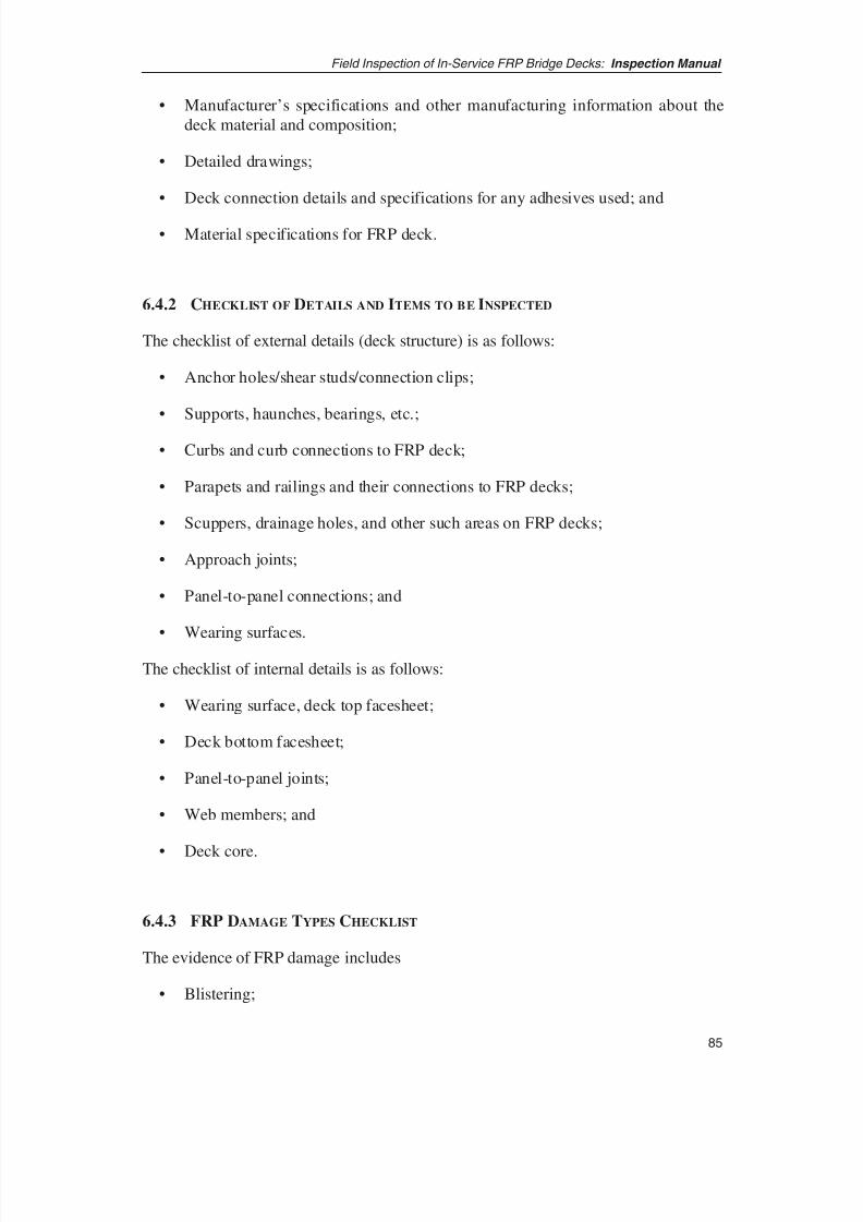
8/8/2019 Inspection of FRP Decks
http://slidepdf.com/reader/full/inspection-of-frp-decks 96/175
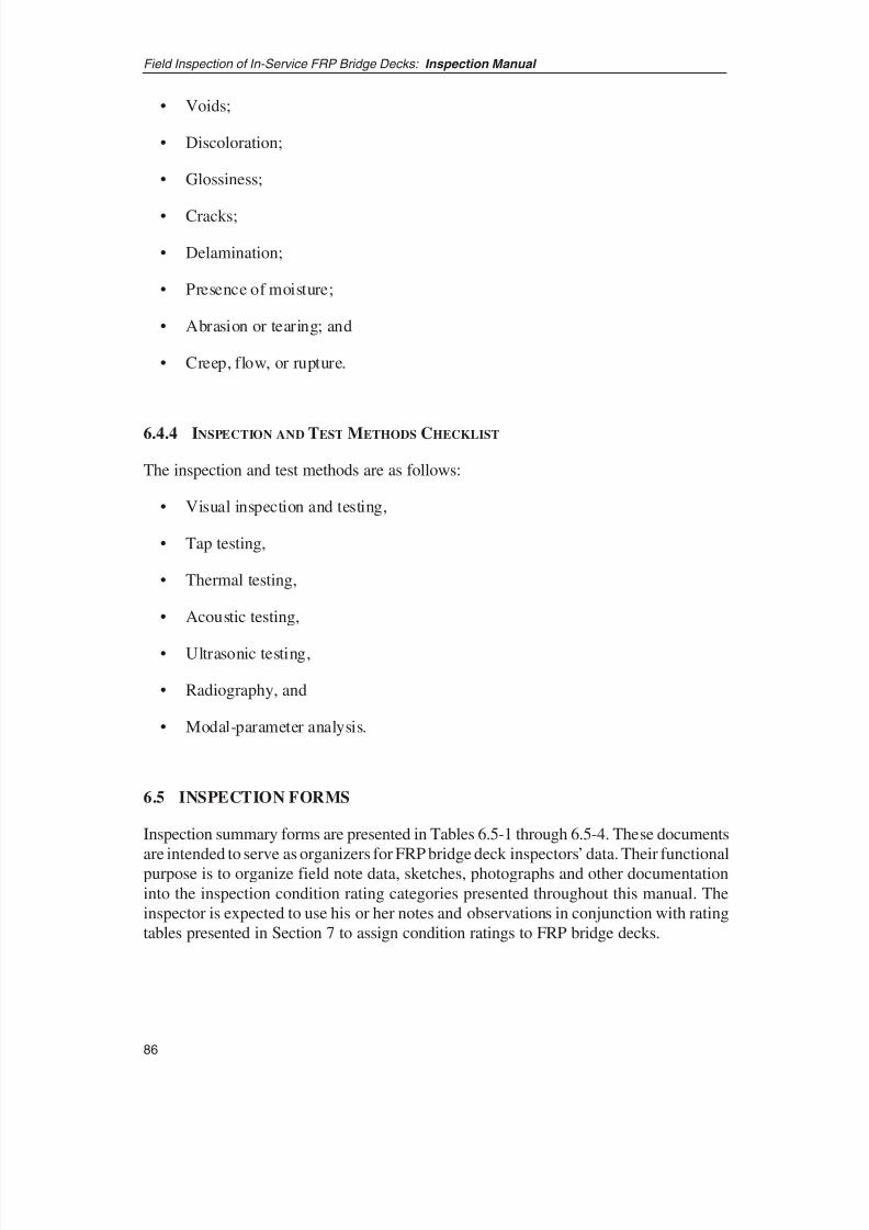
8/8/2019 Inspection of FRP Decks
http://slidepdf.com/reader/full/inspection-of-frp-decks 97/175
• Voids;
• Discoloration;
• Glossiness;
• Cracks;
• Delamination;
• Presence of moisture;
• Abrasion or tearing; and
• Creep, flow, or rupture.
6.4.4 INSPECTION AND TEST METHODS CHECKLIST
The inspection and test methods are as follows:
• Visual inspection and testing,
• Tap testing,
• Thermal testing,
• Acoustic testing,
• Ultrasonic testing,
• Radiography, and
• Modal-parameter analysis.
6.5 INSPECTION FORMS
Inspection summary forms are presented in Tables 6.5-1 through 6.5-4. These documents
are intended to serve as organizers for FRP bridge deck inspectors’ data. Their functionalpurpose is to organize field note data, sketches, photographs and other documentationinto the inspection condition rating categories presented throughout this manual. Theinspector is expected to use his or her notes and observations in conjunction with ratingtables presented in Section 7 to assign condition ratings to FRP bridge decks.
Field Inspection of In-Service FRP Bridge Decks: Inspection Manual
86
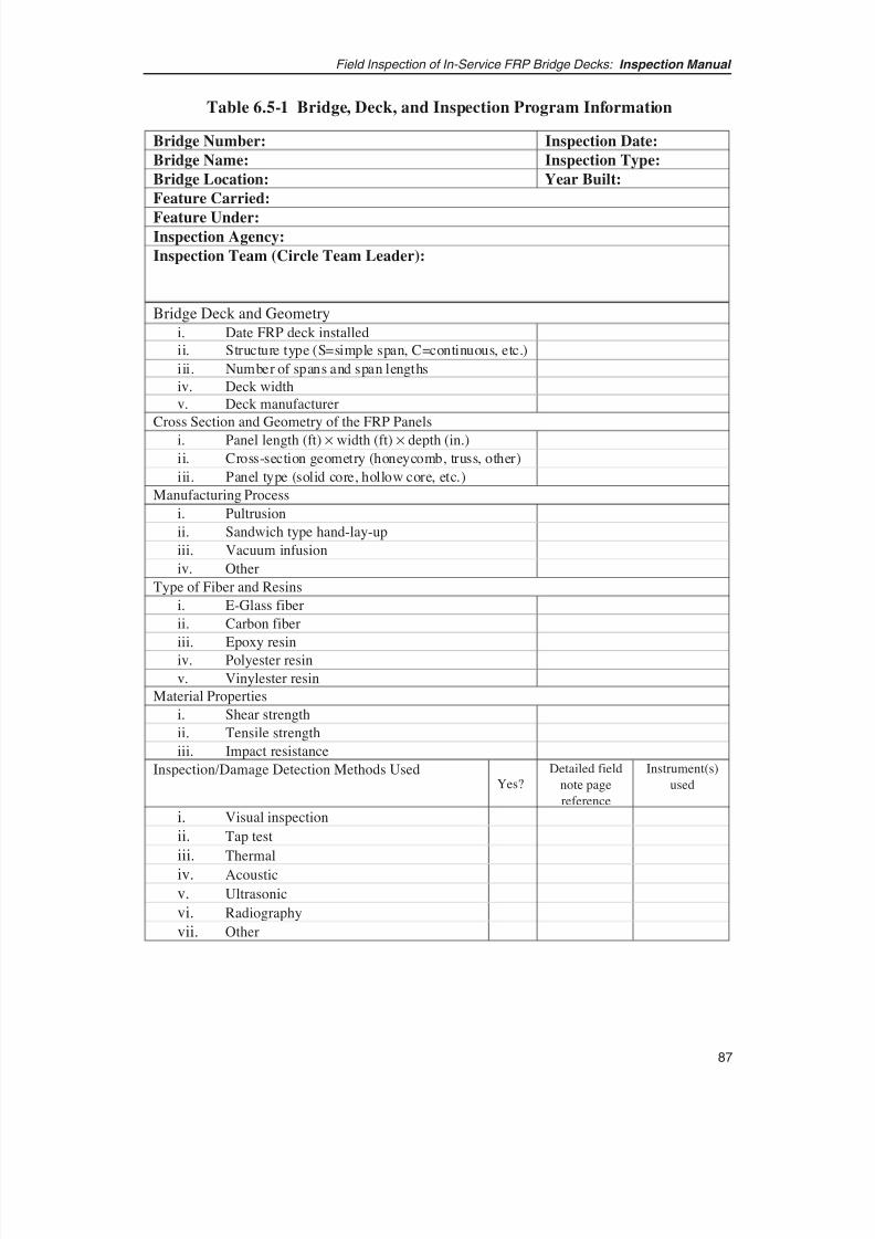
8/8/2019 Inspection of FRP Decks
http://slidepdf.com/reader/full/inspection-of-frp-decks 98/175
87
Field Inspection of In-Service FRP Bridge Decks: Inspection Manual
Inspection/Damage Detection Methods UsedYes?
Detailed field
note page
reference
Instrument(s)
used
i. Visual inspection
ii. Tap test
iii. Thermal
iv. Acoustic
v. Ultrasonic
vi. Radiography
vii. Other
Bridge Number: Inspection Date:
Bridge Name: Inspection Type:
Bridge Location: Year Built:
Feature Carried:
Feature Under:Inspection Agency:
Inspection Team (Circle Team Leader):
Bridge Deck and Geometry
i. Date FRP deck installed
ii. Structure type (S=simple span, C=continuous, etc.)
iii. Number of spans and span lengths
iv. Deck width
v. Deck manufacturer
Cross Section and Geometry of the FRP Panels
i. Panel length (ft) × width (ft) × depth (in.)
ii. Cross-section geometry (honeycomb, truss, other)
iii. Panel type (solid core, hollow core, etc.)
Manufacturing Process
i. Pultrusion
ii. Sandwich type hand-lay-up
iii. Vacuum infusion
iv. Other
Type of Fiber and Resins
i. E-Glass fiber
ii. Carbon fiber
iii. Epoxy resin
iv. Polyester resin
v. Vinylester resin
Material Properties
i. Shear strength
ii. Tensile strength
iii. Impact resistance
Table 6.5-1 Bridge, Deck, and Inspection Program Information
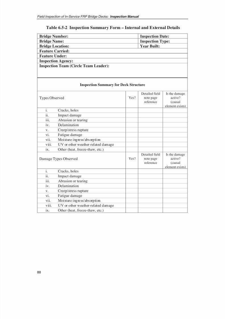
8/8/2019 Inspection of FRP Decks
http://slidepdf.com/reader/full/inspection-of-frp-decks 99/175
Field Inspection of In-Service FRP Bridge Decks: Inspection Manual
88
Damage Types Observed Yes?
Detailed field
note page
reference
Is the damage
active?
(causal
element exists)i. Cracks, holes
ii. Impact damage
iii. Abrasion or tearing
iv. Delamination
v. Creep/stress rupture
vi. Fatigue damage
vii. Moisture ingress/absorption
viii. UV or other weather-related damage
ix. Other (heat, freeze-thaw, etc.)
Bridge Number: Inspection Date:
Bridge Name: Inspection Type:
Bridge Location: Year Built:
Feature Carried:
Feature Under:Inspection Agency:
Inspection Team (Circle Team Leader):
Inspection Summary for Deck Structure
Types Observed Yes?
Detailed field
note page
reference
Is the damage
active?
(causal
element exists)
i. Cracks, holesii. Impact damage
iii. Abrasion or tearing
iv. Delamination
v. Creep/stress rupture
vi. Fatigue damage
vii. Moisture ingress/absorption
viii. UV or other weather-related damage
ix. Other (heat, freeze-thaw, etc.)
Table 6.5-2 Inspection Summary Form – Internal and External Details

8/8/2019 Inspection of FRP Decks
http://slidepdf.com/reader/full/inspection-of-frp-decks 100/175
89
Field Inspection of In-Service FRP Bridge Decks: Inspection Manual
Yes?
Detailed
field note
page
reference
Is the damage
active?
(causal
element exists)
1. Anchorage/shear stud holes
Hole condition
Fraying or other damage
Condition of concrete within hole
Any other signs of distress in and
around the hole
2. Clips and bolts at FRP deck to stringer connections
Bolt/nut tightness
Evidence of movement of clips
Abrasion damage on FRP decks at
clipsCracked or damaged clips
3. Shear studs, haunches, seating of deck on stringers
Condition
Signs of separation of deck from seat
Signs of warping or other distress
4. Panel-to-panel joints
Joint type
Signs of movement
Presence of cracking
Elevation differences between panels
Wearing surface damaged over joint
locationWater leakage through joints evident
5. Approach transverse joints
Spalling or scaling in approach
pavementCracking in deck at approach joint
Settlement of approach pavement
Damage to wearing surface at joint
Bridge Number: Inspection Date:
Bridge Name: Inspection Type:
Bridge Location: Year Built:
Feature Carried:
Feature Under:Inspection Agency:
Inspection Team (Circle Team Leader):
Inspection of Summary for Joints and Connections
Table 6.5-3 Inspection Summary Form for Connections and Joints
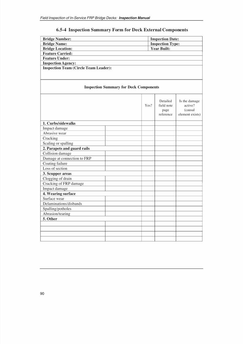
8/8/2019 Inspection of FRP Decks
http://slidepdf.com/reader/full/inspection-of-frp-decks 101/175
Field Inspection of In-Service FRP Bridge Decks: Inspection Manual
90
Yes?
Detailed
field note
page
reference
Is the damage
active?
(causal
element exists)
1. Curbs/sidewalks
Impact damage
Abrasive wear
Cracking
Scaling or spalling
2. Parapets and guard rails
Collision damage
Damage at connection to FRP
Coating failure
Loss of section
3. Scupper areas
Clogging of drain
Cracking of FRP damage
Impact damage
4. Wearing surface
Surface wear
Delaminations/disbands
Spalling/potholes
Abrasion/tearing
5. Other
Bridge Number: Inspection Date:
Bridge Name: Inspection Type:
Bridge Location: Year Built:
Feature Carried:
Feature Under:Inspection Agency:
Inspection Team (Circle Team Leader):
Inspection Summary for Deck Components
6.5-4 Inspection Summary Form for Deck External Components
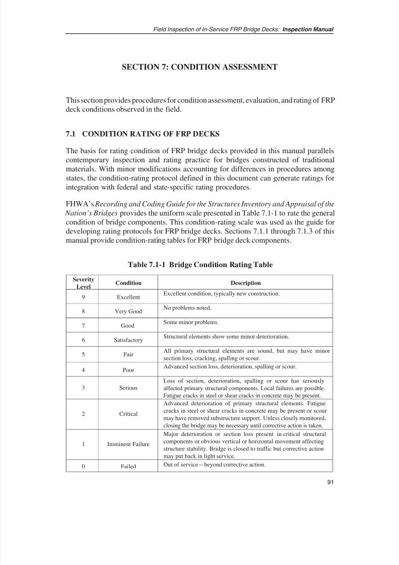
8/8/2019 Inspection of FRP Decks
http://slidepdf.com/reader/full/inspection-of-frp-decks 102/175
SECTION 7: CONDITION ASSESSMENT
This section provides procedures for condition assessment, evaluation, and rating of FRPdeck conditions observed in the field.
7.1 CONDITION RATING OF FRP DECKS
The basis for rating condition of FRP bridge decks provided in this manual parallelscontemporary inspection and rating practice for bridges constructed of traditionalmaterials. With minor modifications accounting for differences in procedures amongstates, the condition-rating protocol defined in this document can generate ratings forintegration with federal and state-specific rating procedures.
FHWA’s Recording and Coding Guide for the Structures Inventory and Appraisal of the
Nation’s Bridges provides the uniform scale presented in Table 7.1-1 to rate the generalcondition of bridge components. This condition-rating scale was used as the guide fordeveloping rating protocols for FRP bridge decks. Sections 7.1.1 through 7.1.3 of thismanual provide condition-rating tables for FRP bridge deck components.
91
Field Inspection of In-Service FRP Bridge Decks: Inspection Manual
Severity
LevelCondition Description
9 ExcellentExcellent condition, typically new construction.
8 Very GoodNo problems noted.
7 GoodSome minor problems.
6 SatisfactoryStructural elements show some minor deterioration.
5 Fair
Poor
All primary structural elements are sound, but may have minor
section loss, cracking, spalling or scour.
4Advanced section loss, deterioration, spalling or scour.
3 Serious
Loss of section, deterioration, spalling or scour has seriously
affected primary structural components. Local failures are possible.
Fatigue cracks in steel or shear cracks in concrete may be present.
2 Critical
Advanced deterioration of primary structural elements. Fatigue
cracks in steel or shear cracks in concrete may be present or scour
may have removed substructure support. Unless closely monitored,
closing the bridge may be necessary until corrective action is taken.
1 Imminent Failure
Major deterioration or section loss present in critical structural
components or obvious vertical or horizontal movement affecting
structure stability. Bridge is closed to traffic but corrective action
may put back in light service.
0 Failed Out of service—beyond corrective action.
Table 7.1-1 Bridge Condition Rating Table
8/8/2019 Inspection of FRP Decks
http://slidepdf.com/reader/full/inspection-of-frp-decks 103/175
7.1.1 GUIDELINES FOR ASSESSMENT AND CONDITION RATING OF FRP DECKS
Tables are presented below for distilling inspection results from the inspection formspresented in Section 6.5 into deck element ratings. The tables and guidelines presentedbelow are a qualitative measure for systematically translating the physical damageidentified through inspection to a condition rating for the structure.
The inspector should be aware that these guidelines are based on limited nationalexperience with condition rating of FRP bridge decks. As such, these will be subject tofuture changes and refinement. Finalizing representative and comprehensive guidelineswill require more information to be generated from field and laboratory evaluation of FRP decks in the next decade.
The inspector is expected to thoughtfully review compiled condition data organized bycategories presented in the tables of Section 6.5, and, quantifying the frequency andvolume of distress observed in inspections, enter the condition rating tables of thissection of the manual to derive a rating on the basis of comparisons with damage
thresholds and observed conditions.
To categorize inspection observations relating various damage levels with the deck condition rating and damage severity levels listed in Table 7.1-1, deck details andcorresponding specific damage types were divided into two categories. The firstcategory, Deck Structure, encompasses important internal deck details (i.e., flanges andweb elements) whose damage and deterioration will have direct influence on thestructural integrity and safety of the deck and the highway bridge. The second groupincorporates other features of the FRP deck, which are critical to function, rideability,durability, and maintenance planning for the bridge.
• Group 1: Deck Structure. This item rates internal and external deck detailsconsisting of flanges, webs, and their connections and the structural condition of the deck. This condition rating reflects the overall condition rating and safety of the deck. Specific signs of damage known to affect these elements include
– Structural damage including cracks (deep or through cracks perpendicular toFRP deck span), delaminations, and voids in FRP matrix, and
– Surface degradation including cracking (shallow surface cracking orcracking parallel to FRP deck span), blistering, wrinkling, discoloration,scratches, and fiber exposure.
• Group 2: Other Deck Features. These include the following:
– Wearing surfaces or overlays. Traffic surfaces degrade with time;establishing degree of wear attributable to normal traffic patterns or resultingfrom accidental overload, impact, vandalism and materials failure isnecessary. Deterioration of wearing surfaces can include delamination,abrasive wear, tearing, cracking, and spalling.
Field Inspection of In-Service FRP Bridge Decks: Inspection Manual
92
8/8/2019 Inspection of FRP Decks
http://slidepdf.com/reader/full/inspection-of-frp-decks 104/175
93
Field Inspection of In-Service FRP Bridge Decks: Inspection Manual
– Joints, including panel-to-panel joints, panel-to-girder joints, and approach joints are rated. Deteriorating FRP deck joints can display separations andopenings between elements, cracking and movement of joints, and damagesto deck elements in the vicinity.
– Railings.
– Curbs.
Condition rating of elements in this latter group will not be used for deck evaluation;however, their condition should be noted in the inspection report.
It is noted that state DOT inspection practice commonly requires that bridge inspectorsassess and note drainage conditions and characteristics of bridges and bridge decks,although ratings are not assigned for this element. The inspector can note in the sectionof Table 6.5-4 under the heading “Other” whether ponding of water on the deck surfaceor debris buildup on the deck or in the drains prevents water from draining.
The following section describes condition rating procedures for the deck structure.Section 7.1.3 provides the inspector tables to rate condition of other deck features.
7.1.2 CONDITION RATING OF THE FRP DECK STRUCTURE
Because of differences between the characteristics and structural behavior of FRP decksand those of other types of decks, the established damage thresholds and definitions cannotbe used directly and without modification to rate the condition of FRP deck structures.Accordingly, an approach unique to FRP decks is adopted here for determining the damagethresholds and incorporating these into the rating tables. The approach considers thedamage types common for this type of structure and takes into account the potential fordamage progression. Damage such as cracks (shallow or deep, parallel or perpendicular toFRP panel span) and other surface degradations are assumed to have implications similarto those posed by comparable structural, functional, and durability damage in othercommon types of deck structures. Therefore, the thresholds for these types of damages,including their extent expressed in percentage of deck area, are extracted from establishedcondition rating tables (e.g., Michigan Structure Inventory and Appraisal Coding Guide,Appendix B: Bridge Safety Inspection Report [BSIR] Rating Definitions, BIR 6).
For delaminations and voids within the FRP deck flanges and between flanges and webelements, however, the potential for damage progression unique to this type of structurebecomes the determining factor. Evaluating the likelihood of progression of any type of damage within the FRP deck will require judgment based on damage metrics foundwithin the FRP composites industry. Clearly, any level of damage is undesirable, butonce damage is discovered, the specific decision to be made is whether it is severeenough to require immediate lane closure and repair or whether action can be delayedwithout threatening public safety or the deck’s overall performance. As discussed inprevious sections, the main load-carrying member of a sandwich panel is the topfacesheet, which is continually subject to material stresses from direct traffic and impact
8/8/2019 Inspection of FRP Decks
http://slidepdf.com/reader/full/inspection-of-frp-decks 105/175
loads. The top facesheet is the first structural element that will require scrutiny upon thediscovery of any deterioration or signs of damage on the wear surface.
The two most significant damage conditions for the facesheet are (1) the separation of layers within in the facesheet, defined as a “delamination,” and (2) the more severe caseof full detachment of a facesheet section from the underlying core, referred to as a
“debonded facesheet.” These damage conditions may not be directly detectable duringroutine inspections unless their size is significant enough to produce a visible bulge onthe top surface. The presence of noncritical damage to surrounding structural elementssuch as reflective cracking in the wear surface or local damage to joints may signal theinitiation of delamination, so closer examination of the underlying facesheet would benecessary. If no visible signs of physical change are apparent in the facesheet, thenfurther examination is not needed. If a physical change or anomaly is discovered, theinspector then has to determine whether the conditions indicate a delamination ordebond.
A methodology, which is proposed to determine whether a delamination will
likely progress if unattended, is described in detail in Appendix 9 of the report (the reportis bound with this manual, see p. 124; the report’s appendixes are published attrb.org/news/blurb_detail.asp?id=5905). Here, the results are considered to derivedamage thresholds that can be incorporated directly into the condition rating tables. Forsimplicity, separation of layers in a facesheet and full detachment of a facesheet from theweb core are considered and called “delamination” for rating purposes. The procedure isbased on a simplified approach taken from the damage inspection of honeycombsandwich panels in the aircraft industry. The methodology is not intended to be a rigorousexamination of failure, but is an approximate approach to determine whether furtherfailure is likely based on measurable size of delaminations.
Figure 7.1.2-1 represents critical delamination dimensions for a common 8-in.-deep FRPdeck with spans of 4, 6, 8, and 10 ft using the analysis from Appendix 9 of the report.The chart was developed based on a HS25 wheel loading with an impact factor of 30%;different load and impact factor charts can be developed for alternate combinations. Asafety factor of 3 is incorporated in this chart. Four curves illustrate the relationshipbetween facesheet (flange) thickness and the critical delamination size for four spanlengths. The critical delamination size is defined as a limiting defect dimension.Delaminations with defect dimensions less than or equal to the critical size will notpropagate under the influence of HS25 loading.
The dashed lines show the flange thicknesses corresponding to each span length,
assuming that the flange was designed originally for HS25 wheel load (ignoring deadload). With this assumption, the horizontal coordinate of the intersection between eachdashed line with the corresponding curve for the same span length determines anapproximate critical delamination size for that span length. The facesheet thicknessrequired for a 4-ft to 10-ft span deck ranges from approximately 0.22 in. to 0.55 in. Thecorresponding critical delamination sizes vary from 6 in. to 15 in.
Therefore, for an 8-in.-deep FRP deck, depending on span of interest, a delamination sizesmaller than 6 in. to 15 in. in diameter can be tolerated without structural degradation.
Field Inspection of In-Service FRP Bridge Decks: Inspection Manual
94
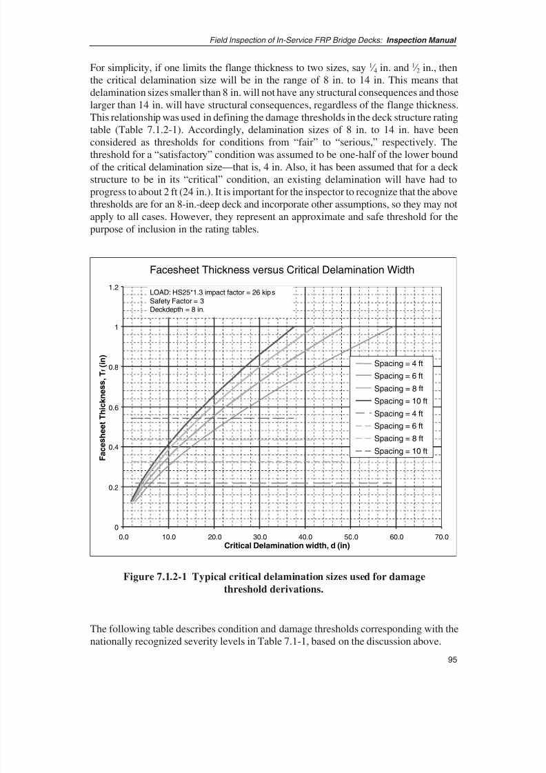
8/8/2019 Inspection of FRP Decks
http://slidepdf.com/reader/full/inspection-of-frp-decks 106/175
95
Field Inspection of In-Service FRP Bridge Decks: Inspection Manual
For simplicity, if one limits the flange thickness to two sizes, say 1 ⁄ 4 in. and 1 ⁄ 2 in., thenthe critical delamination size will be in the range of 8 in. to 14 in. This means thatdelamination sizes smaller than 8 in. will not have any structural consequences and thoselarger than 14 in. will have structural consequences, regardless of the flange thickness.This relationship was used in defining the damage thresholds in the deck structure rating
table (Table 7.1.2-1). Accordingly, delamination sizes of 8 in. to 14 in. have beenconsidered as thresholds for conditions from “fair” to “serious,” respectively. Thethreshold for a “satisfactory” condition was assumed to be one-half of the lower boundof the critical delamination size—that is, 4 in. Also, it has been assumed that for a deck structure to be in its “critical” condition, an existing delamination will have had toprogress to about 2 ft (24 in.). It is important for the inspector to recognize that the abovethresholds are for an 8-in.-deep deck and incorporate other assumptions, so they may notapply to all cases. However, they represent an approximate and safe threshold for thepurpose of inclusion in the rating tables.
Facesheet Thickness versus Critical Delamination Width
0
0.2
0.4
0.6
0.8
1
1.2
0.0 10.0 20.0 30.0 40.0 50.0 60.0 70.0
Critical Delamination width, d (in)
F a c e s h e e t T h i c
k n e s s ,
T f ( i n )
Spacing = 4 ft
Spacing = 6 ft
Spacing = 8 ft
Spacing = 10 ft
Spacing = 4 ft
Spacing = 6 ft
Spacing = 8 ft
Spacing = 10 ft
LOAD: HS25*1.3 impact factor = 26 kips
Safety Factor = 3
Deckdepth = 8 in.
Figure 7.1.2-1 Typical critical delamination sizes used for damage
threshold derivations.
The following table describes condition and damage thresholds corresponding with thenationally recognized severity levels in Table 7.1-1, based on the discussion above.
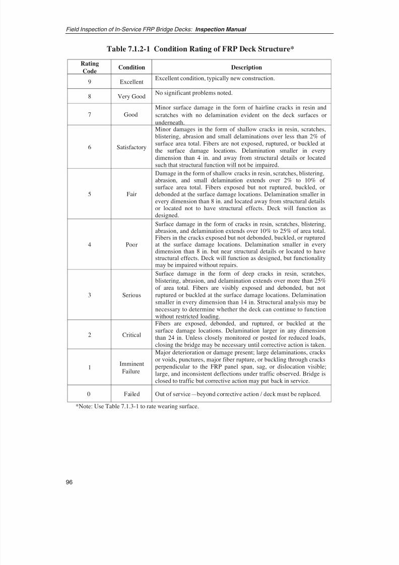
8/8/2019 Inspection of FRP Decks
http://slidepdf.com/reader/full/inspection-of-frp-decks 107/175
Field Inspection of In-Service FRP Bridge Decks: Inspection Manual
96
Rating
CodeCondition Description
9 ExcellentExcellent condition, typically new construction.
8 Very Good
No significant problems noted.
7 GoodMinor surface damage in the form of hairline cracks in resin and
scratches with no delamination evident on the deck surfaces or
underneath.
6 Satisfactory
Minor damages in the form of shallow cracks in resin, scratches,blistering, abrasion and small delaminations over less than 2% of surface area total. Fibers are not exposed, ruptured, or buckled atthe surface damage locations. Delamination smaller in every
dimension than 4 in. and away from structural details or locatedsuch that structural function will not be impaired.
5 Fair
Damage in the form of shallow cracks in resin, scratches, blistering,abrasion, and small delamination extends over 2% to 10% of surface area total. Fibers exposed but not ruptured, buckled, ordebonded at the surface damage locations. Delamination smaller inevery dimension than 8 in. and located away from structural detailsor located not to have structural effects. Deck will function asdesigned.
4 Poor
Surface damage in the form of cracks in resin, scratches, blistering,abrasion, and delamination extends over 10% to 25% of area total.Fibers in the cracks exposed but not debonded, buckled, or rupturedat the surface damage locations. Delamination smaller in everydimension than 8 in. but near structural details or located to havestructural effects. Deck will function as designed, but functionalitymay be impaired without repairs.
3 Serious
2 Critical
Fibers are exposed, debonded, and ruptured, or buckled at thesurface damage locations. Delamination larger in any dimensionthan 24 in. Unless closely monitored or posted for reduced loads,closing the bridge may be necessary until corrective action is taken.
1Imminent
Failure
Major deterioration or damage present; large delaminations, cracksor voids, punctures, major fiber rupture, or buckling through cracksperpendicular to the FRP panel span, sag, or dislocation visible;large, and inconsistent deflections under traffic observed. Bridge isclosed to traffic but corrective action may put back in service.
0 Failed Out of service—beyond corrective action / deck must be replaced.
*Note: Use Table 7.1.3-1 to rate wearing surface.
Surface damage in the form of deep cracks in resin, scratches,blistering, abrasion, and delamination extends over more than 25%of area total. Fibers are visibly exposed and debonded, but not
ruptured or buckled at the surface damage locations. Delaminationsmaller in every dimension than 14 in. Structural analysis may benecessary to determine whether the deck can continue to functionwithout restricted loading.
Table 7.1.2-1 Condition Rating of FRP Deck Structure*
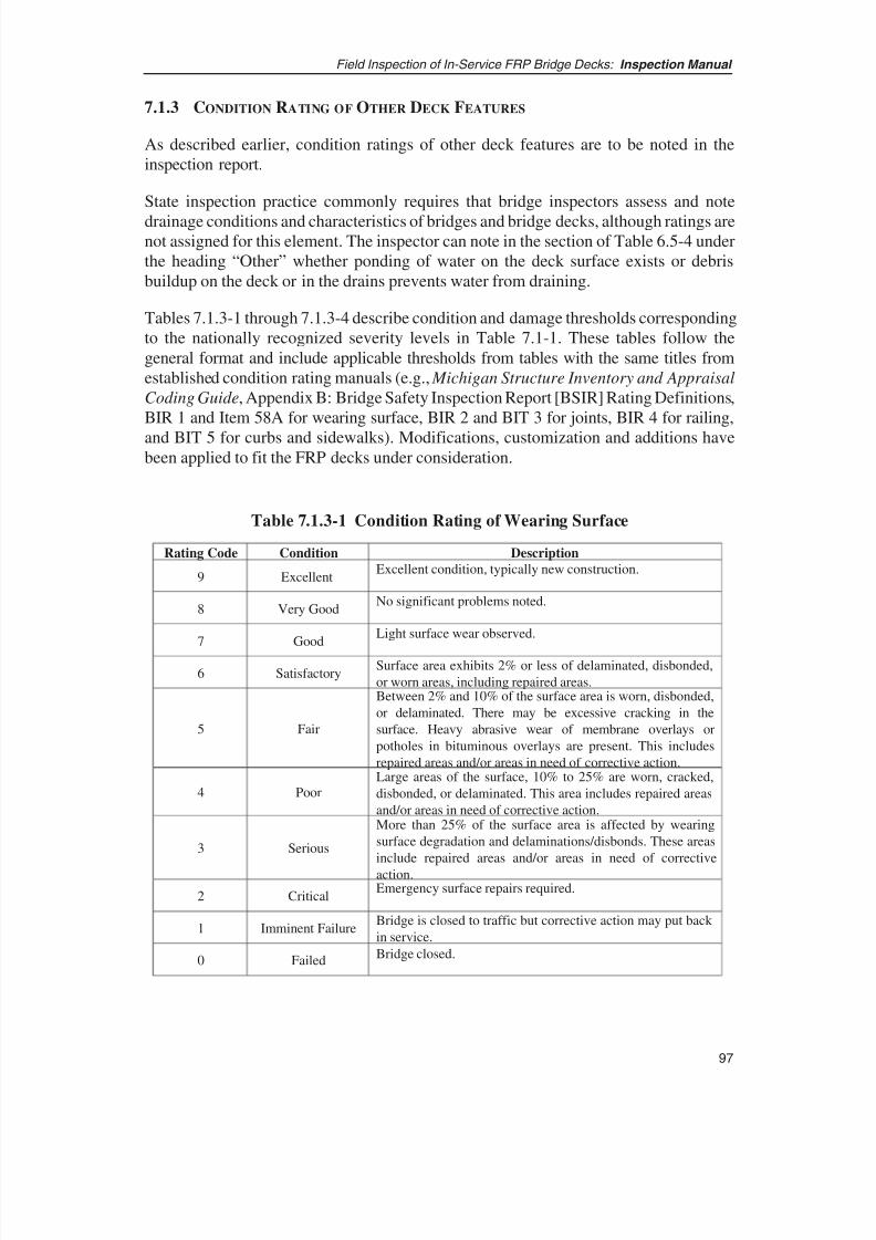
8/8/2019 Inspection of FRP Decks
http://slidepdf.com/reader/full/inspection-of-frp-decks 108/175
97
Field Inspection of In-Service FRP Bridge Decks: Inspection Manual
Rating Code Condition Description
9 ExcellentExcellent condition, typically new construction.
8 Very GoodNo significant problems noted.
7 GoodLight surface wear observed.
6 SatisfactorySurface area exhibits 2% or less of delaminated, disbonded,
or worn areas, including repaired areas.
5 Fair
Between 2% and 10% of the surface area is worn, disbonded,
or delaminated. There may be excessive cracking in the
surface. Heavy abrasive wear of membrane overlays or
potholes in bituminous overlays are present. This includes
repaired areas and/or areas in need of corrective action.
4 PoorLarge areas of the surface, 10% to 25% are worn, cracked,
disbonded, or delaminated. This area includes repaired areas
and/or areas in need of corrective action.
3 Serious
More than 25% of the surface area is affected by wearing
surface degradation and delaminations/disbonds. These areas
include repaired areas and/or areas in need of corrective
action.
2 CriticalEmergency surface repairs required.
1 Imminent FailureBridge is closed to traffic but corrective action may put back
in service.
0 FailedBridge closed.
7.1.3 CONDITION RATING OF OTHER DECK FEATURES
As described earlier, condition ratings of other deck features are to be noted in theinspection report.
State inspection practice commonly requires that bridge inspectors assess and note
drainage conditions and characteristics of bridges and bridge decks, although ratings arenot assigned for this element. The inspector can note in the section of Table 6.5-4 underthe heading “Other” whether ponding of water on the deck surface exists or debrisbuildup on the deck or in the drains prevents water from draining.
Tables 7.1.3-1 through 7.1.3-4 describe condition and damage thresholds correspondingto the nationally recognized severity levels in Table 7.1-1. These tables follow thegeneral format and include applicable thresholds from tables with the same titles fromestablished condition rating manuals (e.g., Michigan Structure Inventory and Appraisal
Coding Guide, Appendix B: Bridge Safety Inspection Report [BSIR] Rating Definitions,BIR 1 and Item 58A for wearing surface, BIR 2 and BIT 3 for joints, BIR 4 for railing,
and BIT 5 for curbs and sidewalks). Modifications, customization and additions havebeen applied to fit the FRP decks under consideration.
Table 7.1.3-1 Condition Rating of Wearing Surface

8/8/2019 Inspection of FRP Decks
http://slidepdf.com/reader/full/inspection-of-frp-decks 109/175
Field Inspection of In-Service FRP Bridge Decks: Inspection Manual
98
Rating
CodeCondition Description
9 ExcellentExcellent condition, typically new construction.
8 Very GoodNo problems noted.
7 Good
Minor deterioration with hairline cracks less than 1/32 in.
(0.8 mm). No noticeable water leakage observed from
underside.
6 Satisfactory
Minor deterioration with shallow hairline cracks greater than
1/32 in. (0.8 mm) and shallow spalls/delamination within 2 ft
of the joint. No noticeable water leakage.
5 Fair
Evidence of joint degradation visible due to cracking in
overlay or topping above panel joint locations. Gaps andcracks of up to 1/16 in. width over 10% of length; no loss of
bolts, clips or other devices. Signs of water leakage through
joints present.
4 Poor
Gaps and cracks of up to 1/4 in. over 20% of length, few clips
or bolts loose or lost, elevation changes for adjacent panels
evident, crack movement observed with passing traffic loads.
Widespread signs of water leakage through joints.
3 Serious
2 Critical
1 Imminent FailureBridge is closed to traffic but corrective action may put back
in service.
0 Failed Bridge closed.
Gaps and cracks of up to 1/2 in. over 30% of length, 5%
of clips or bolts loose or lost, elevation changes for
adjacent panels, noticeable differential vertical or
horizontal movement of the adjacent panels in traffic.
Gaps and cracks wider than 1 in. and/or over 50% of length,
20% of clips or bolts loose or lost, large elevation differences
between adjacent panels evident. Wearing surface
extensively degraded in joint locations. Closing the bridge
necessary unless emergency repairs are made.
Table 7.1.3-2 Condition Rating of Joints
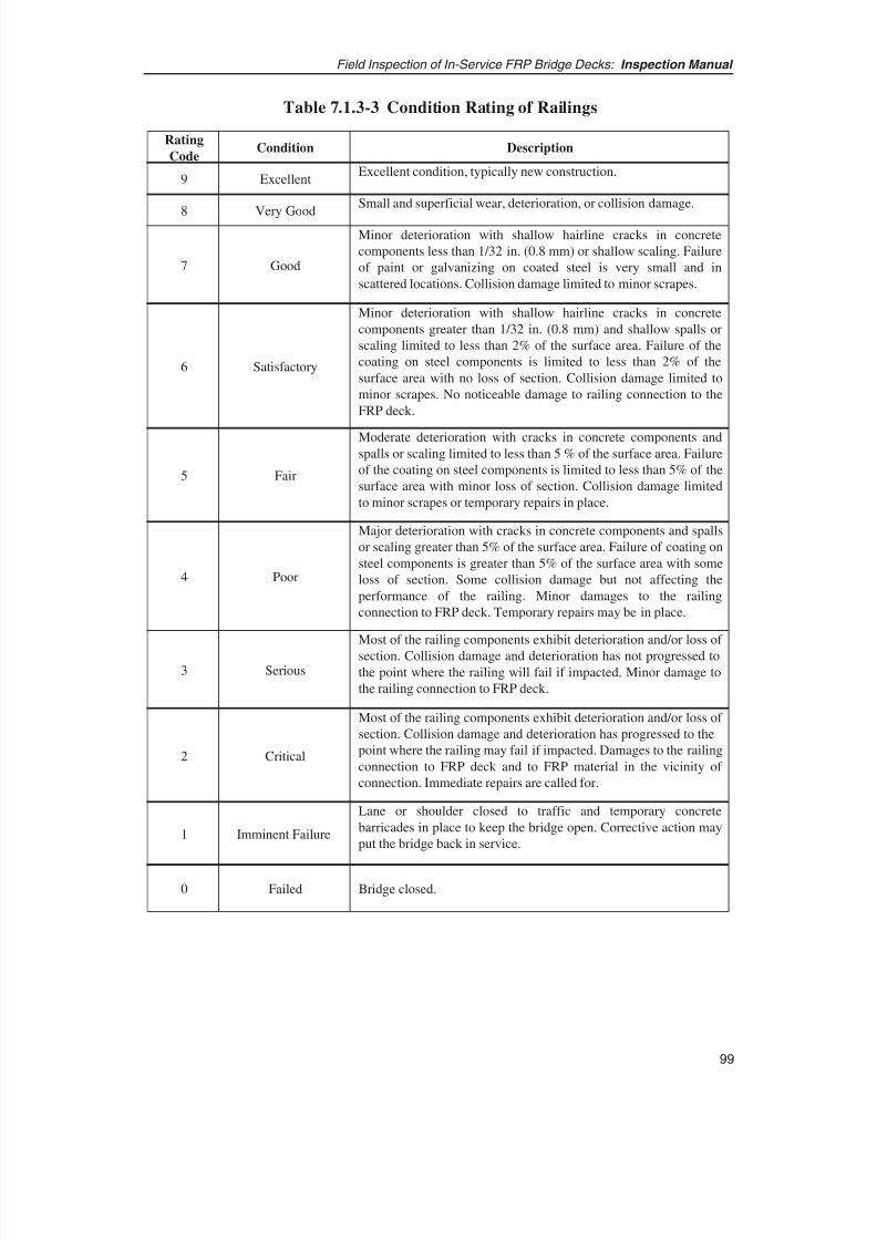
8/8/2019 Inspection of FRP Decks
http://slidepdf.com/reader/full/inspection-of-frp-decks 110/175

8/8/2019 Inspection of FRP Decks
http://slidepdf.com/reader/full/inspection-of-frp-decks 111/175
Field Inspection of In-Service FRP Bridge Decks: Inspection Manual
100
Rating Code ConditionDescription
9 ExcellentExcellent condition, typically new construction.
8 Very Good
Minor cracking less than 1/32 in. wide (0.8 mm) with no spal-
ling, scaling, or delamination.
7 GoodOpen cracks less than 1/16 in. wide (1.6 mm) at a spacing of 10 ft
or more, light shallow scaling allowed.
6 Satisfactory
Surface has considerable number of open cracks greater than 1/16 in.
wide (1.6 mm) at a spacing of 5 ft or less. Surface area exhibits 2% or
less of spalled or delaminated areas, including repaired areas.
Medium scaling on the surface is 1/4 in. to 1/2 in. (6.4 mm to
13 mm) in depth.
5 Fair
Between 2% and 10% of the surface area is spalled or delaminated.
There can be excessive cracking in the surface. Heavy scaling 1/2
in. to 1 in. in depth (13 mm to 26 mm) can be present. This
includes repaired areas and/or areas in need of corrective action.
4 Poor
Large areas of the surface, 10% to 25%, are spalled or delaminated.
This includes repaired areas and/or areas in need of corrective action.
Spalls and scaling are not deep.
3 Serious
More than 25% of the surface area is spalled. This area includes
repaired areas and/or areas in need of corrective action. Spalls and
scaling are not deep.
2 CriticalEmergency surface repairs required by the crews.
1 Imminent FailureSidewalk or shoulder is closed, but corrective action may put it back
in service.
0 FailedBridge closed.
Table 7.1.3-4 Condition Rating of Curbs and Sidewalks
7.2 CORRELATION OF DAMAGE TO LIKELY CAUSES
This section provides guidance on how to relate a field-observed defect or damage to thetypes of loading or external condition that might have caused it. Adverse effects of loading often can be observed from visual evidence. The visual evidence typicallyconsists of surface conditions such as chalking (ASTM D4214-89); checking (ASTMD660-93); cracking (ASTM D661-93); blistering (ASTM D714-94); and flaking (ASTM
D772-86). In addition, FRP surface material can exhibit discoloration and loss of gloss(reflectivity) as a result of damage from exposure to radiation, chemicals, or fire. Allthese visual clues provide a means for the inspector to identify and isolate potentialdamage and its probable cause.
8/8/2019 Inspection of FRP Decks
http://slidepdf.com/reader/full/inspection-of-frp-decks 112/175
7.2.1 EFFECTS OF VEHICULAR LOADS
Evidence of the effects of vehicular loads can be divided into two distinct categories: (1)damage due to normal vehicular traffic over the bridge and (2) the damage due toaccidental vehicle or vehicle-induced impact.
7.2.1.1 Effects of Normal Vehicular Traffic
Damage due to normal vehicular traffic primarily affects the wearing surface and, to alimited extent, the panel joints and approach joints. Any damage from normal vehiculartraffic would entail wear and tear of the wearing surface and potential abrasion at jointswhere components can move relative to each other. Visible signs of normal vehiculartraffic–induced damage typically include
• Ruts or tire marks on the wearing surface;
• Map cracks or minor surface indentations on the wearing surface;
• Appearance of abrasion at panel joints, deck-to-stringer joints and clips, approach joints, the interface of curbs and decks, and the interface of parapets/railings andthe deck; and
• Discoloration or loss of gloss on FRP surfaces.
7.2.1.2 Effect of Vehicle or Vehicle-Induced Impact
Damage due to vehicular impact can typically occur at the curbs, parapets, approachguardrails, and approach joints. In addition, impact damage due to debris and rock hitsas a result of vehicular motion can occur at other parts of the FRP decks. Such impact,if strong enough, will typically cause FRP material to indent and crack at the point of contact. Discoloration or loss of surface gloss may also be visible at and near the impactlocation. In addition, if the force of impact is sufficiently high, reflective cracking aroundthe impact point may also be observed. The impact damage will typically be superficial,but in some cases, could penetrate the full depth of the FRP skin. Depending on theparticular impacted component and the location of vehicular impact, there possibly couldbe additional indirect damage to other components in the vicinity of the impact.
7.2.2 EFFECT OF PUNCHING LOADS
FRP material, and particularly FRP decks, have high tensile strength as compared withconventional bridge materials such as steel and concrete. Laboratory testing has shownthat this higher tensile strength makes FRP decks unlikely to fail or be damaged due topurely bending stresses. However, FRP deck components such as facesheets or wearingsurfaces are relatively weak under directly applied loads. Therefore, heavy loads (highload per unit area) directly applied to FRP decks could in certain circumstances causepunching-type failures of FRP deck surfaces. In this type of failure, the deck surfaces or
101
Field Inspection of In-Service FRP Bridge Decks: Inspection Manual
8/8/2019 Inspection of FRP Decks
http://slidepdf.com/reader/full/inspection-of-frp-decks 113/175

8/8/2019 Inspection of FRP Decks
http://slidepdf.com/reader/full/inspection-of-frp-decks 114/175
103
Field Inspection of In-Service FRP Bridge Decks: Inspection Manual
7.2.3.1.3 Freeze-Thaw Effects
Within the normal temperature range, freeze-thaw typically has little effect on low-void-ratio composites, since a low void content keeps frozen moisture from being absorbedby the FRP and causing any appreciable damage. However, even with a low void ratio,severe thermal cycling can cause microcracks to form and grow. These microcracks can
coalesce to form matrix cracks, leading to degradation of stiffness and other matrix-dominated properties.
7.2.3.2 Radiation
The effect of UV radiation on FRP composites is well documented from extensiveresearch and testing undertaken in the defense and aerospace fields. Solar ultravioletradiation has been shown to be deleterious to organic materials, and polymers are thusgreatly affected by exposure to UV radiation.
However, the effects of UV exposure are generally reduced by applying UV-resistant
coatings or similar treatments to exposed FRP surfaces. Light-stable resins and pigmentshave also been developed to further enhance the long-term stability of FRP compositestructures exposed to radiation. Radiation typically affects only the top few microns of the exposed surface. Therefore, the UV degradation effect on structural properties of thicker sections is not as critical as on thin sections. However, the effects of temperature,moisture, wind-borne abrasives, and other environmental conditions complicate theinfluence of radiation and, despite radiation protection, could adversely affect FRPcomponents.
Visual evidence of radiation-related damage can be observed on FRP surfaces exposedto solar radiation. Prolonged exposure of FRP material to sunlight typically results in
hardening of the matrix, as well as color change or loss of pigment. Loss of gloss andluster and surface discoloration are signs that indicate potential radiation damage of FRP.
7.2.3.3 Chemicals
Chemicals, especially alkaline solutions, can degrade the main constituents of FRPcomposites. This is particularly true of bare glass fibers, where a reaction with an alkalinesolution forms expansive silica gels. However, the composite system as a whole can bedesigned to provide superior chemical resistance by selecting appropriate constituentmaterials and resins. The typical visual signs of damage due to chemicals includediscoloration and blistering.
7.2.3.4 Moisture
The effect of moisture depends on characteristics of the material and other environmentalconditions such as temperature. Temperature influences the quantity, distribution, andrate of water absorption into the composite material. As temperature increases, theamount and rate increase rapidly. In some cases, water accumulated at the fiber/matrixinterface contributes substantially to the shear strength loss of the material. It has alsobeen shown that ingress of water through voids in a composite can cause the resin to
8/8/2019 Inspection of FRP Decks
http://slidepdf.com/reader/full/inspection-of-frp-decks 115/175
plasticize. Absorption of water by FRP and freeze-thaw cycles thereafter can result infreeze-thaw-initiated damage of FRP decks. Visible signs of moisture ingress in thecomposite could be bulging and swelling of composite surfaces and, in some extremecases, the visible presence of water.
7.2.3.5 Fire
The resin component of most FRP is undoubtedly combustible, and as this forms asignificant proportion of the material, it must be taken seriously in any consideration of fire. Different resins exhibit various characteristics, and a number of retarding low-smoke additives are available to customize fire response still further. However, fire candamage the resin, resulting in loss of composite action between the fibers and resin anda subsequent loss in FRP strength. In addition, the matrix can ignite and releasepotentially harmful toxic smoke. Signs of fire damage range from char and burn marksto signs of melted resins, warping of FRP sections, and blistering. Loss of color and glossalso typically accompany fire damage.
7.2.4 OTHER EFFECTS
Other loads that can have significant effect on long-term behavior of FRP decks includecreep and fatigue.
7.2.4.1 Creep
Creep is the permanent deflection of a material under long-term loading. Like mostconventional construction materials, FRP composites are prone to creep under sustainedloading. However, virtually all creep comes from the visco-elastic behavior of thepolymer resin and very little from the glass reinforcements. Thus, creep would existmainly in load conditions that would impart high and sustained shear or compressionforces on the section of composite material with high resin content. Because creep is aresin-dependent phenomenon, the amount of creep depends on temperature andoperating environment. For example, FRP materials demonstrate higher creep levels athigher temperatures and also higher creep levels when submerged in liquid rather thanin air. Typically, maintaining stresses below appropriate working stress levels controlscreep. There are no specific visual signs of creep. However, creep can be assessed bymonitoring and comparing deck deflection over a period of time.
7.2.4.2 Fatigue
Fatigue characteristics represent the response of a material to cyclic loading. Repeatedcyclic loading usually results in a decrease in strength properties of the material. Limitedresearch is available on fatigue behavior of FRP decks. However, cyclic loading datafrom FRP specimens for wind turbine blades showed cycles to failure stabilizing past1x106 at 33% of laminate ultimate stress under tension/compression reverse cycles andpast 1x10⁷ at 50% of ultimate stress under tension/tension loading. These tests wereperformed under full cyclic compression/tension cycles, so the results represent the
Field Inspection of In-Service FRP Bridge Decks: Inspection Manual
104

8/8/2019 Inspection of FRP Decks
http://slidepdf.com/reader/full/inspection-of-frp-decks 116/175
105
Field Inspection of In-Service FRP Bridge Decks: Inspection Manual
worst-case fatigue condition. In most cases, the sections of FRP decks would besubjected to zero-tension or zero-compression cycles due to the on-and-off nature of traffic loads, so fatigue conditions would be far less severe. Consequently, one can expectthe strength to stabilize at cycles less than the indicated cycles to failure under fullcompression/tension conditions. In addition, deflection/stiffness governs the design of FRP decks in most cases and they are typically designed with a high factor of safety (2.5or more) so that the working stresses typically fall well under 50% of material strength.This presents a significant advantage over concrete, for example, in terms of tensile loadcapacity.
7.3 EVALUATION OF CONTINUED EXISTENCE OF CAUSAL ELEMENTS
An inspector must be able not only to detect the defect or distress and its likely causalelement, but also to ascertain whether the causal element continues to exist on the bridge.The inspector should make every attempt first to identify the causal element and, second,
to assess whether the causal element continues to exist. If the causal element continuesto exist, then the inspector should flag the observation, requesting immediate action toremove or mitigate the causal element.
7.4 REFERENCE
1. Bach, P. “High Cycle Fatigue of Glass Fibre Reinforced Polyester,” Proceedings
of IEA Workshop on Fatigue in Wind Turbines, ETSU, Harwell, 1988.
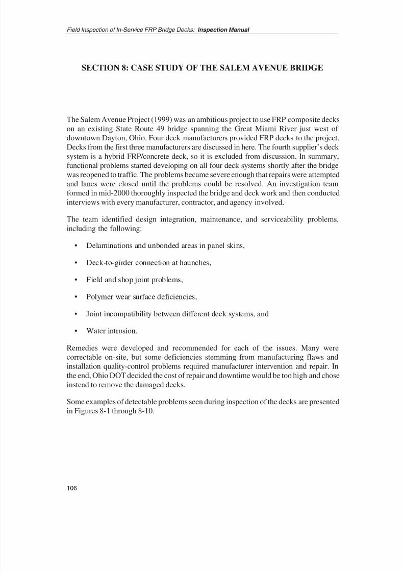
8/8/2019 Inspection of FRP Decks
http://slidepdf.com/reader/full/inspection-of-frp-decks 117/175
SECTION 8: CASE STUDY OF THE SALEM AVENUE BRIDGE
The Salem Avenue Project (1999) was an ambitious project to use FRP composite deckson an existing State Route 49 bridge spanning the Great Miami River just west of downtown Dayton, Ohio. Four deck manufacturers provided FRP decks to the project.Decks from the first three manufacturers are discussed in here. The fourth supplier’s deck system is a hybrid FRP/concrete deck, so it is excluded from discussion. In summary,functional problems started developing on all four deck systems shortly after the bridgewas reopened to traffic. The problems became severe enough that repairs were attemptedand lanes were closed until the problems could be resolved. An investigation teamformed in mid-2000 thoroughly inspected the bridge and deck work and then conducted
interviews with every manufacturer, contractor, and agency involved.
The team identified design integration, maintenance, and serviceability problems,including the following:
• Delaminations and unbonded areas in panel skins,
• Deck-to-girder connection at haunches,
• Field and shop joint problems,
• Polymer wear surface deficiencies,
• Joint incompatibility between different deck systems, and
• Water intrusion.
Remedies were developed and recommended for each of the issues. Many werecorrectable on-site, but some deficiencies stemming from manufacturing flaws andinstallation quality-control problems required manufacturer intervention and repair. Inthe end, Ohio DOT decided the cost of repair and downtime would be too high and choseinstead to remove the damaged decks.
Some examples of detectable problems seen during inspection of the decks are presentedin Figures 8-1 through 8-10.
Field Inspection of In-Service FRP Bridge Decks: Inspection Manual
106

8/8/2019 Inspection of FRP Decks
http://slidepdf.com/reader/full/inspection-of-frp-decks 118/175
107
Field Inspection of In-Service FRP Bridge Decks: Inspection Manual
Figure 8-1 Walk-through inspection on Salem Bridge; wear surface cracking
and spalling observed.
Figure 8-2 Wear surface lift on deck.
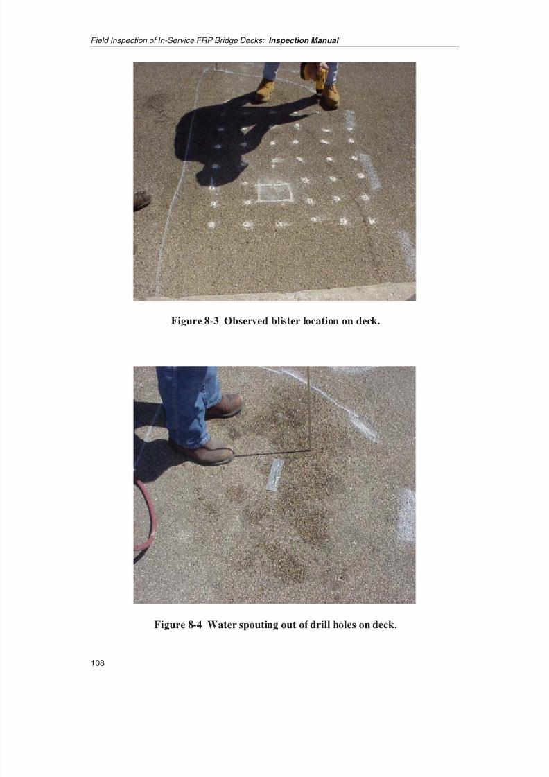
8/8/2019 Inspection of FRP Decks
http://slidepdf.com/reader/full/inspection-of-frp-decks 119/175
Field Inspection of In-Service FRP Bridge Decks: Inspection Manual
108
Figure 8-3 Observed blister location on deck.
Figure 8-4 Water spouting out of drill holes on deck.

8/8/2019 Inspection of FRP Decks
http://slidepdf.com/reader/full/inspection-of-frp-decks 120/175
109
Field Inspection of In-Service FRP Bridge Decks: Inspection Manual
Figure 8-5 Haunch inspection shows deck rise.
Figure 8-6 Tap tests indicate debonding of facesheet.

8/8/2019 Inspection of FRP Decks
http://slidepdf.com/reader/full/inspection-of-frp-decks 121/175
Field Inspection of In-Service FRP Bridge Decks: Inspection Manual
110
Figure 8-7 Coring through deck.
Figure 8-8 No adhesive between facesheet and core webs.
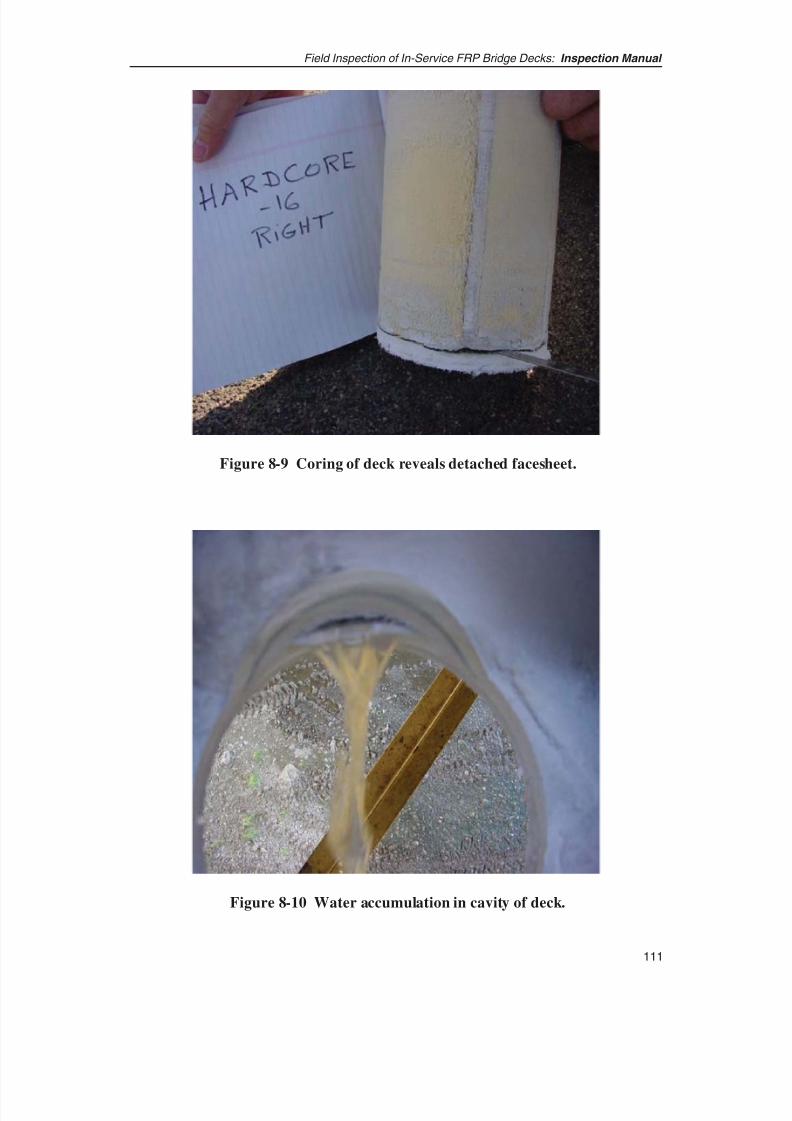
8/8/2019 Inspection of FRP Decks
http://slidepdf.com/reader/full/inspection-of-frp-decks 122/175
111
Field Inspection of In-Service FRP Bridge Decks: Inspection Manual
Figure 8-9 Coring of deck reveals detached facesheet.
Figure 8-10 Water accumulation in cavity of deck.
8/8/2019 Inspection of FRP Decks
http://slidepdf.com/reader/full/inspection-of-frp-decks 123/175
GLOSSARY OF COMMON COMPOSITES INDUSTRY TERMS
Adhesive – Substance capable of holding materials together by surface attachment.Adhesive types include a monomer of at least one of the polymers to be joined, catalyzedto produce a bond by polymerization; solvent cement that dissolves the plastics being joined, forming strong intermolecular bonds, and then evaporates; bonded adhesives orsolvent solutions of resins, sometimes containing plasticizers, which dry at roomtemperature; and reactive adhesives or those containing partially polymerized resins (e.g.,epoxies, polyesters, or phenolics), which cure with the aid of catalysts to form a bond.
ASNT – American Society of Nondestructive Testing.
Balanced laminate – A composite laminate in which all laminae at angles other than 0°and 90° occur only in plus or minus pairs (not necessarily adjacent) and are symmetricalabout a centerline.
Barcol hardness – Value obtained by measuring the resistance to penetration of a sharp,spring-loaded steel point. The value can be used as a measure of the degree of cure of aplastic.
Blemish – Any surface imperfection of a coating or substrate.
Blistering – A localized swelling and separation between any of the layers of a laminate.
Calcium carbonate – Used as fillers for plastics. They are obtained from naturallyoccurring deposits as well as by chemical precipitation. The natural material is derivedfrom natural chalk, limestone or dolomite, consisting of calcium carbonate with up toabout 44% magnesium carbonate.
Carbon fibers – A group of fibrous materials essentially composed of elemental carbon.They may be prepared by pyrolysis of organic fibers, the most widely used method.Carbon and graphite fibers are used interchangeably. Graphite fibers are the stiffest fibersknown and have very high strengths and moduli that remain constant at hightemperatures. The higher the graphite content, the stiffer the fiber, but the lower thestrength. Less expensive pitch-based fibers are an alternative to graphite fibers.
CFRP – Carbon-fiber reinforced plastic, a general term covering any type of plasticreinforced cloth, mat, strands, or any other form of fibrous glass.
Chop strand – A type of glass fiber reinforcement consisting of strands of individualglass fibers that have been chopped into short lengths and bonded together within thestrands so that they remain in bundles after chopping.
112
Field Inspection of In-Service FRP Bridge Decks: Inspection Manual
8/8/2019 Inspection of FRP Decks
http://slidepdf.com/reader/full/inspection-of-frp-decks 124/175
113
Field Inspection of In-Service FRP Bridge Decks: Inspection Manual
Clay filler – Naturally occurring sediments rich in hydrated silicates of aluminum,predominating in particles of colloidal or near-colloidal size. Those of particular interestto the plastics industry such as kaolin or china clay are used as fillers in epoxy andpolyester resins.
Cocure – The process of curing several different materials in a single step. Examples
include the curing of various prepregs to produce hybrids or the curing of compositematerials and structural adhesives to produce sandwich structure or skins with integrallymolded fittings.
Coefficient of thermal expansion (CTE) – The fractional change in length (orsometimes in volume, when specified) of a material for a unit change in temperature.
Composite material – A material, usually manmade, that is a three-dimensionalcombination of at least two chemically distinct materials with a distinct interfaceseparating the components, created to obtain properties that cannot be achieved by anyof the components acting alone.
Continuous mat – Reinforcement fabric made with continuous fiber strands randomlybonded to form a flat sheet.
Core – The central member of a laminate to which the faces of the sandwich areattached.
Cross-linking – The establishing of chemical links between the molecular chains inpolymers. When extensive, as in most thermosetting resins, cross-linking makes oneinfusible super-molecule of all the chains forming a three-dimensional or network polymer, generally by covalent bonding. Thermosetting materials cross-link under the
influence of heat and/or catalysis, irradiation with high-energy electron beams, orchemical cross-linking agents, such as organic peroxides.
Cure time – The period of time during which a part is subjected to heat and/or pressureto cure the resin.
Debond – An area of separation within or between plies in a laminate or within a bonded joint, which can be caused by improper adhesion during processing, contamination, ordamaging interlaminar stresses.
Debulk – The compacting or squeezing out of air and volatiles between plies or prepreglaminates under moderate heat and vacuum to ensure seating on the tool, to preventwrinkles, and to promote adhesion.
Delaminate – To separate existing layers or split a laminated plastic material along theplane of its layers. It is the resultant effect of physical separation or loss of bond betweenlaminate plies through failure of the adhesive.
8/8/2019 Inspection of FRP Decks
http://slidepdf.com/reader/full/inspection-of-frp-decks 125/175

8/8/2019 Inspection of FRP Decks
http://slidepdf.com/reader/full/inspection-of-frp-decks 126/175
115
Field Inspection of In-Service FRP Bridge Decks: Inspection Manual
can be formed into yarn without twist or with very low twist. Used in filament windingprocesses and in filamentary composites that require long continuous strands.
Foam – Composite foams include syntactic and other foams such as graphite-urethane.Thermoplastic foams are also available for molding large parts: rigid foams are useful ascore materials for sandwich construction.
FRP – Fibrous-glass reinforced plastic, a general term covering any type of plasticreinforced cloth, mat, strands, or any other form of fibrous glass.
Gel time – Time for conversion of a liquid to a gel state. The point in the curing cycle atwhich a dramatic increase in viscosity occurs due to initial network formation.
Gelcoat – (1) A quick-setting resin used in molding processes to provide an improvedsurface for the composite. (2) The first resin applied to the mold after the mold-releaseagent, which becomes an integral part of the finished laminate and is usually used toimprove surface appearance. (3) High-build, chemical-resistant, thixotropic polyester
coating.
GFRP – Glass fiber reinforced plastic.
Glass cloth – Conventionally woven glass fiber material.
Glass fiber reinforcement – A family of reinforcing materials for reinforced plasticsbased on single filaments of glass ranging in diameter from 3 to 19 micrometers (0.00012in. to 0.00075 in.).
Glass mat – A thin mat of glass fibers with or without a binder.
Graphite fibers – See Carbon fibers.
Honeycomb – A manufactured product consisting of resin-impregnated sheet material(paper, glass fabric, etc.) or sheet metal, formed into hexagonal-shaped cells. Used as acore material and bonded with face sheets in a sandwich construction. The core isassumed to have no stiffness in the plane of the sandwich panel and infinite stiffnessnormal to the panel.
Hygoscopic – Having the tendency to absorb moisture from the air. Some resins arehygroscopic, thus requiring drying before molding.
Interlaminar anomaly – Descriptive term pertaining to some object (a void), event (afracture), or potential field (a shear stress) referenced as existing or occurring betweentwo or more adjacent laminae.
Laminate – A product made by bonding together two or more layers or laminae of material. In the reinforced plastics industry, the term refers mainly to superimposedlayers of resin-impregnated or resin-coated fabrics or fibrous reinforcements that havebeen bonded together, usually by heat and pressure, to form a single piece.

8/8/2019 Inspection of FRP Decks
http://slidepdf.com/reader/full/inspection-of-frp-decks 127/175
Laminate, angle-ply – Consists of an arbitrary number of layers identical in thicknessand material and having alternating directions + x and − x.
Laminate, cross-ply – Consists of an arbitrary number of layers of the same materialand thickness but with alternating orientations of 0° and 90°. This bidirectional laminateis orthotropic and has a Poisson’s ratio of nearly 0.
Laminate, isotropic – A laminate in which the strength properties are equal in alldirections.
Laminate, orthotropic – A ply geometry of laminate that must be arranged so that thegross in-plane elastic properties of the laminate possess three mutually perpendicularplanes of symmetry parallel respectively to the sides of the specimen.
Laminate, symmetric – A stacking sequence of plies below the laminate midplane thatmust be a mirror image of the stacking sequence above the midplane.
Layup – (1) A process of fabrication that involves the stacking of plies of material in aspecified orientation and sequence. (2) As used in reinforced plastics, the process of placing the reinforcing material in position in the mold or the resin-impregnatedreinforcement. (3) A description of the component materials, geometry, and so forth, of a laminate.
Mandrel – A form around which pultruded and filament-wound structures are shapedor used for the base in the production of a part by lay-up or filament winding.
Mat – A fibrous material for reinforced plastic consisting of randomly oriented choppedfilaments or swirled filaments with a binder cut to the contour of a mold, for use in
reinforced plastics processes such as matched-die molding and hand lay-up or contactpressure molding.
Matrix – As applied to polymer matrix materials, it is the resinous phase of a reinforcedplastic material in which the fibers or filaments of a composite are embedded.
MEKP – Abbreviation for Methyl Ethyl Ketone Peroxide, a curing agent for polyesterresins.
Modulus of Elasticity – The ratio of stress (nominal) to corresponding strain below theproportional limit of a material. It is expressed in force per unit area, usually pounds persquare inch or kilograms-force per square centimeter.
Modulus of Rupture – The force necessary to break a flexure specimen of specifiedwidth and thickness in bending expressed in pounds-force per square inch.
Modulus, Young’s – Modulus of Elasticity.
NDE – Nondestructive evaluation.
Field Inspection of In-Service FRP Bridge Decks: Inspection Manual
116

8/8/2019 Inspection of FRP Decks
http://slidepdf.com/reader/full/inspection-of-frp-decks 128/175
117
Field Inspection of In-Service FRP Bridge Decks: Inspection Manual
NDI – Nondestructive inspection.
NDT – Nondestructive testing.
Orientation angle – The relative angle of the warp direction in a fabric to the chosenzero direction shown on the face of the drawing. It would probably be the yarn or tow
direction in a unidirectional tape.
Outgassing – The evolution of embedded gas from a material by heat.
Peeling – The detachment of one layer from another because of poor adherence.
Ply – As applied to laminates, the layers of fiber or reinforcements.
Polyesters – Alkyd thermosetting resins characterized by vinyl unsaturation in thepolyester backbone. These unsaturated polyesters are most widely used in reinforcedplastics. These are the simplest, most versatile, economical, and widely used family of
resins. Reinforced matrices can be compression molded, filament wound, continuouslypultruded, injection molded, centrifugally cast, corn-formed, and cold molded.
Post cure – Additional elevated temperature cure usually without pressure to improvefinal properties or complete the cure.
Pot life – The length of time that a catalyzed resin system retains a viscosity low enoughto be used in processing.
Preform – A preshaped fibrous reinforcement, of mat or cloth, formed to desired shapeon a mandrel or mock-up prior to being placed in a mold press.
Resin transfer molding (RTM) – Molding process in which catalyzed resin is pumpedinto a two-sided, matched mold where fibrous reinforcement has been placed. The moldand/or resin may or may not be heated. RTM offers the ability to consolidate structuralparts.
Sandwich construction – A structural panel concept consisting, in its simplest form, of two relatively thin, dense, high-strength and parallel sheets of structural material withtheir faces bonded to and separated by a relatively thick, lightweight core such ashoneycomb or foamed plastic.
Stitching – A series of stitches embodied in a material such as woven textile fabric.
Tow – An untwisted bundle of continuous untwisted filaments. A term commonly usedin referring to carbon or graphite fibers.
Ultimate strength – The term used to describe the maximum unit stress that a materialcan withstand when subjected to an applied load in a compression, tension, or shear test.
8/8/2019 Inspection of FRP Decks
http://slidepdf.com/reader/full/inspection-of-frp-decks 129/175
Ultrasonic C-scan – A nondestructive inspection technique for composites in which ashort pulse of ultrasonic energy is incident on a sample. Measurement of the transmittedpulse indicates the sample’s attenuation of the incident pulse. The attenuation of the pulseis influenced by voids, delaminations, state of resin cure, the fiber volume fraction, thecondition of the fiber/matrix interface, and any foreign inclusions present.
Ultrasonic testing (UT) – A nondestructive test applied to elastic sound-conductivematerials to locate inhomogeneities or structural discontinuities.
Vacuum-assisted resin transfer molding (VARTM) – An infusion process by whicha vacuum draws resin into a one-sided mold; a cover, either rigid or flexible, is placedover the laminate and taped or otherwise fixed to form a vacuum-tight seal.
Vinyl ester resins – A family of resins chemically similar to both unsaturated polyestersand epoxy resins. They were developed as a compromise between the two materials,providing the simplicity and low cost of polyesters and the thermal and mechanicalproperties of epoxies. Vinyl esters can also be used in wet layups and liquid molding
processes such as resin transfer molding.
Void – (1) In a solid plastic or laminate, a void is an unfilled space sufficiently large toscatter light. (2) A pocket or gas entrapment within or between the plies of reinforcement.
Void content – The percentage of voids in a laminate by volume.
Waffle core – A type of sandwich construction containing a deep-drawn third sheet thatacts as a core to separate and hold the two face sheets in position.
Water absorption – The ratio of the weight of water absorbed by a material to the weight
of the dry materials.
Waviness – Readily noticeable elevations and/or depressions, including defects such asbuckles or ridges.
Wet layup – The process of forming an article by first applying a liquid resin to thesurface of a mold and then applying a reinforcing backing layer.
Wrinkle – A surface imperfection in reinforced plastics where one or more plies of prepreg are formed into a ridge with the appearance of a crease or wrinkle.
X-ray – Electromagnetic waves produced by the bombardment of a target with cathode
rays.
Field Inspection of In-Service FRP Bridge Decks: Inspection Manual
118

8/8/2019 Inspection of FRP Decks
http://slidepdf.com/reader/full/inspection-of-frp-decks 130/175
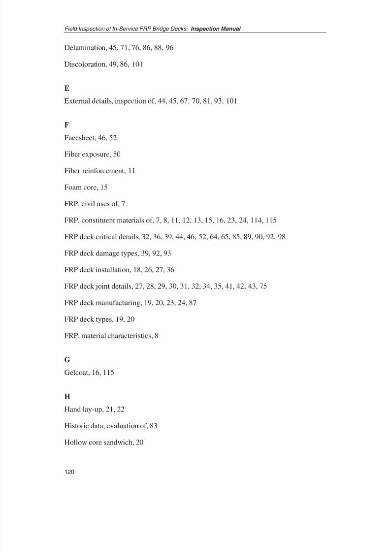
8/8/2019 Inspection of FRP Decks
http://slidepdf.com/reader/full/inspection-of-frp-decks 131/175
Delamination, 45, 71, 76, 86, 88, 96
Discoloration, 49, 86, 101
E
External details, inspection of, 44, 45, 67, 70, 81, 93, 101
F
Facesheet, 46, 52
Fiber exposure, 50
Fiber reinforcement, 11
Foam core, 15
FRP, civil uses of, 7
FRP, constituent materials of, 7, 8, 11, 12, 13, 15, 16, 23, 24, 114, 115
FRP deck critical details, 32, 36, 39, 44, 46, 52, 64, 65, 85, 89, 90, 92, 98
FRP deck damage types, 39, 92, 93
FRP deck installation, 18, 26, 27, 36
FRP deck joint details, 27, 28, 29, 30, 31, 32, 34, 35, 41, 42, 43, 75
FRP deck manufacturing, 19, 20, 23, 24, 87
FRP deck types, 19, 20
FRP, material characteristics, 8
G
Gelcoat, 16, 115
H
Hand lay-up, 21, 22
Historic data, evaluation of, 83
Hollow core sandwich, 20
Field Inspection of In-Service FRP Bridge Decks: Inspection Manual
120
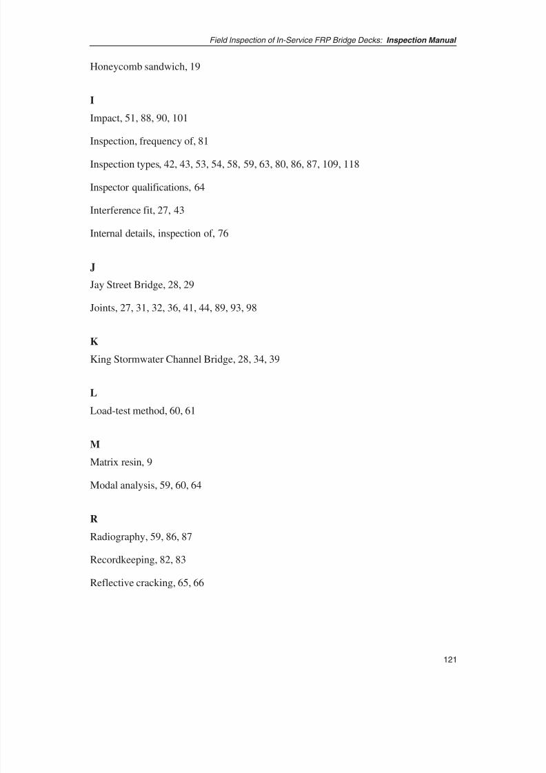
8/8/2019 Inspection of FRP Decks
http://slidepdf.com/reader/full/inspection-of-frp-decks 132/175
121
Field Inspection of In-Service FRP Bridge Decks: Inspection Manual
Honeycomb sandwich, 19
I
Impact, 51, 88, 90, 101
Inspection, frequency of, 81
Inspection types, 42, 43, 53, 54, 58, 59, 63, 80, 86, 87, 109, 118
Inspector qualifications, 64
Interference fit, 27, 43
Internal details, inspection of, 76
JJay Street Bridge, 28, 29
Joints, 27, 31, 32, 36, 41, 44, 89, 93, 98
K
King Stormwater Channel Bridge, 28, 34, 39
L
Load-test method, 60, 61
M
Matrix resin, 9
Modal analysis, 59, 60, 64
R
Radiography, 59, 86, 87
Recordkeeping, 82, 83
Reflective cracking, 65, 66
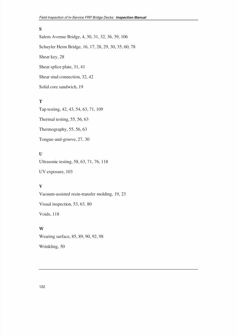
8/8/2019 Inspection of FRP Decks
http://slidepdf.com/reader/full/inspection-of-frp-decks 133/175
S
Salem Avenue Bridge, 4, 30, 31, 32, 36, 39, 106
Schuyler Heim Bridge, 16, 17, 28, 29, 30, 35, 60, 78
Shear key, 28
Shear splice plate, 31, 41
Shear stud connection, 32, 42
Solid core sandwich, 19
T
Tap testing, 42, 43, 54, 63, 71, 109
Thermal testing, 55, 56, 63
Thermography, 55, 56, 63
Tongue-and-groove, 27, 30
U
Ultrasonic testing, 58, 63, 71, 76, 118
UV exposure, 103
V
Vacuum-assisted resin-transfer molding, 19, 23
Visual inspection, 53, 63, 80
Voids, 118
W
Wearing surface, 85, 89, 90, 92, 98
Wrinkling, 50
Field Inspection of In-Service FRP Bridge Decks: Inspection Manual
122

8/8/2019 Inspection of FRP Decks
http://slidepdf.com/reader/full/inspection-of-frp-decks 134/175
PART II:
REPORT
8/8/2019 Inspection of FRP Decks
http://slidepdf.com/reader/full/inspection-of-frp-decks 135/175
SUMMARY: REPORT
After the Cold War, the technology transfer initiatives taken by the federal government
to use the unused manufacturing capacities of composite manufacturers in the military
and space industries resulted in the proliferation of fiber reinforced polymers (FRP)
usage in the bridge industry. Some of these companies capitalized on the potential of the
transportation market and were instrumental in advancement of FRP use on bridge
structures. Since the 1990s, numerous bridges with FRP decks have been built in the
United States, and the number of such bridges is continuously growing as bridge
engineers become comfortable with the material and its performance. However, most of
these bridge decks have been built using proprietary and/or experimental systems and
details. The lack of standardization has been a challenge to bridge engineers, whotraditionally are accustomed to standard shapes, sizes, and material properties. In
addition, variations in the design and composition of FRP decks have resulted in unique
problems and maintenance issues associated with each type, further complicating the
upkeep of these decks.
As the usage of FRP decks becomes more widespread, the state DOTs will need to have
guidelines and uniform standards to inspect, assess, and evaluate the condition of their
in-service FRP deck bridges.
This study was undertaken to help state DOTs and other bridge owners assess the
condition of FRP bridge decks in their inventory. This study’s goals are (1) to developrecommended uniform guidelines for the inspection and condition evaluation of in-
service FRP bridge decks and (2) to develop a course to train bridge inspectors in the
methods for inspecting FRP bridge decks. The study is based on state-of-the-art
knowledge of FRP material and decks, ongoing research, experiences from state DOTs’
experimental FRP deck projects, experiences of the defense and aerospace industries
with use of FRP materials, and the state of current practice in the use and assessment of
this material in the United States and abroad. The manual and course target the practicing
engineer or inspector, and the content and organization of the manual are devised to
supplement the existing bridge inspection manuals and courses offered by FHWA.
The research team completed Tasks 1 through 10 of this research project inaccordance with the research plan. This final report documents the project and
its significant milestones and contains required project deliverables. The appendixes
compiled during the report’s technology review are available online at
trb.org/news/blurb_detail.asp?id=5905 (see p. 163 for a list of appendixes).
124
8/8/2019 Inspection of FRP Decks
http://slidepdf.com/reader/full/inspection-of-frp-decks 136/175
CHAPTER 1
INTRODUCTION AND RESEARCH APPROACH
The objective of NCHRP Project 10-64, “Field Inspection of In-Service FRP Bridge
Decks” (initiated by the project research team on April 24, 2003) was to develop a
recommended manual and an inspector’s training course for field inspection of in-service
FRP bridges. Currently, there are no uniform standards or guidelines for field inspection
of in-service FRP bridge decks. As the usage of FRP decks becomes more widespread,
state DOTs will need uniform standards to inspect, assess, and evaluate the condition of
their in-service FRP deck bridges. This project endeavored to add to current knowledge
on FRP decks in order to develop a uniform approach to inspecting, assessing, andevaluating them. The project was accomplished through successful execution of 10 tasks
outlined in the project statement. The final report presented herein documents the
research program.
1.1 BACKGROUND
Historically, composite materials—FRP in particular—have been used extensively in
many areas, ranging from highly complex aerospace and military applications to more
routine applications such as liquid storage tanks, fishing rods, and truck bedliners. Due
to their low weight, high strength, and significant durability advantages, the most
prevalent nonconsumer use of FRP material has been in the military aviation and civilian
space applications. Although the defense and aerospace industry readily adopted
composite materials in the 1960s, it took another 20 years before the bridge industry
adopted them as viable alternatives to traditional materials.
One of the earliest uses of FRP materials in a U.S. bridge superstructure commenced in
1994, when Lockheed Martin designed, fabricated, and tested a 30-ft-span, all-composite
FRP bridge (1). The design effort and subsequent testing program lasted 1 year, and the
bridge was eventually installed on a private road at a federal facility in Idaho;
instrumentation, testing, and evaluation continued on the bridge. However, the first all-
composite-superstructure vehicular bridge on a U.S. public road was installed in 1996 in
Russell, Kansas (2). Several small-span all-composite bridges have since been built in
other states, but the use of all-composite structures has been experimental, and limited
to small bridges on lightly traveled rural roads. On the other hand, due to its significantly
lower weight and inherent durability advantage over traditional materials such as
reinforced concrete, FRP is seeing wider acceptance and use in relatively less critical but
maintenance-intensive and dead-weight-sensitive components such as bridge decks.
125
Field Inspection of In-Service FRP Bridge Decks: Report

8/8/2019 Inspection of FRP Decks
http://slidepdf.com/reader/full/inspection-of-frp-decks 137/175
The number of FRP-decked bridges is continuously growing as bridge engineers become
more comfortable with the material and its performance. The lack of standardization,
however, has been a challenge to bridge engineers, who traditionally are accustomed to
standard shapes, sizes, and material properties. In addition, variations in the design and
composition of FRP decks have resulted in unique problems and maintenance issues
associated with each type, thereby further complicating the upkeep of these decks.
Most studies and research to date have been focused either on understanding the behavior
of FRP decks or on verifying and monitoring in-service performance (3–8). However,
increased usage of FRP decks will require uniform standards for inspection, assessment,
and evaluation of these bridge components (9). In the developmental stages of FRP
bridge technology, load testing and dynamic response (modal) testing have been used for
assessing the condition of FRP decks. Although these methods provide important
condition-related information, the information is global in nature and does not provide
clues to potential future problems. The relative complexity of the FRP material and its
deterioration modes that—unlike those of conventional materials—do not necessarily
provide visual clues make the inspection and assessment of FRP decks even more
difficult.
It was thought that inspection protocols for bridge decks could be drawn from the
aerospace industry, which has made extensive use of FRP composites for decades.
However, there are fundamental differences in inspection and maintenance philosophies
between the aerospace and highway transportation sectors. Aircraft structures are
normally inspected and maintained daily, whereas highway bridges are inspected every
2 years. The differences in inspection frequency and a much more wear-prone
application on a bridge make it difficult to use directly the design, inspection, and
maintenance philosophies from defense and aerospace industries. In addition, bridge
engineers and inspectors are accustomed to working with less fragile materials such as
steel and concrete, which show distinct visual clues when they are damaged or
deteriorated. Although signs do exist for FRP material condition, the bridge inspectors
acquainted with traditional materials have yet to be indoctrinated, and the visual clues
are not yet cataloged or adapted for use by the bridge engineering community. As
identified by Mertz et al. (9), a “lack of easy and reliable inspection and repair
procedures” therefore necessitates development of simple indicators and procedures
comparable with those that practicing bridge engineers and technicians now use for
conventional materials such as steel and concrete.
1.2 NCHRP PROJECT STATEMENT AND RESEARCH TASKS
To address the need for practical guidelines in the inspection and assessment of FRP
decks, NCHRP developed the following project statement for Project 10-64:
Guidelines and recommended field procedures for inspection of in-service
fiber reinforced polymer (FRP) bridge decks are needed. Inspection and
monitoring of FRP structures varies widely, from no monitoring, to visual
Field Inspection of In-Service FRP Bridge Decks: Report
126

8/8/2019 Inspection of FRP Decks
http://slidepdf.com/reader/full/inspection-of-frp-decks 138/175
127
Field Inspection of In-Service FRP Bridge Decks: Report
inspection, to experimental NDE techniques. The criteria for field
inspection should be based on identification of critical components of FRP
decks and determination of critical accumulated damage thresholds in
those components. Modal analysis, global inspection techniques, and
remote monitoring are already being employed on FRP structures for
overall condition assessment. An emphasis on techniques for point
damage detection is needed. Other inspection issues include accuracy and
reliability requirements for inspection data, continuous versus periodic
data collection, depth and frequency of inspection, reliability requirements
for equipment and sensors, and calibrating the guidelines with field project
data.
In addition, the type of inspection data collected and the recording format
varies. As a consequence, it is difficult to compare one project to another.
Thus, there is a need for a standard inspection reporting format to make
such comparisons possible. Comparative data would also help the
composites industry to refine the technology to better meet the states’
needs.
The objective of this project is to develop recommended field procedures,
evaluation guidelines, and reporting standards for periodic inspection of
in-service FRP bridge decks. A training course for FRP bridge deck
inspectors shall also be developed.
The project was conducted through execution of the following 10 tasks:
• Task 1: Prepare an assessment of performance data, research findings, and otherinformation to determine the failure modes and serviceability problems of FRP
bridge decks. Catalog critical details, damage types, and the accumulated damage
thresholds for each type of FRP bridge deck. This information shall be assembled
from technical literature and from unpublished experiences of engineers, owners,
fabricators, and others.
• Task 2: Describe the state of inspection practice for FRP bridge decks and
identify applicable FRP inspection procedures from other industries. The
applicability and effectiveness of visual inspection procedures should be
thoroughly evaluated. Documented field performance, especially as it relates to
predictions based on the results of current inspection practices, is of particularinterest. Field procedures, evaluation guidelines, and reporting standards shall be
assessed for speed and economy of use, and for their suitability for integration
into the states’ bridge inspection programs.
• Task 3: Determine suitable inspection procedures for each critical detail, damage
type, and deck type identified in Task 1. With an emphasis on point damage

8/8/2019 Inspection of FRP Decks
http://slidepdf.com/reader/full/inspection-of-frp-decks 139/175
detection, select procedures from those identified in Task 2 based on technical,
operational, and economic criteria. Document and justify the reasons for these
selections. Clearly identify details, damage types, and deck types for which no
suitable inspection procedures exist.
• Task 4: Prepare a detailed outline of an inspection manual for FRP bridge decks.
The outline shall include recommended record keeping requirements, relevant
data items, and a proposed inspection report format.
• Task 5: Submit an interim report that documents the results of Tasks 1 through
4. Following project panel review of the interim report, meet with the panel to
discuss the interim report and the remaining tasks. NCHRP approval of the
interim report will be required before proceeding with the remaining tasks.
• Task 6: Develop a draft inspection manual based on the approved outline. The
manual shall be prepared in the format used in FHWA’s Safety Inspection of In-
Service Bridges: Participant Notebook (10).
• Task 7: Develop an instructors guide and appropriate training materials for a
course on field inspection and documentation of the condition of FRP bridge
decks.
• Task 8: Revise the inspection manual, the training guide, and training materials
consistent with panel comments.
• Task 9: Plan and conduct a pilot training course on FRP bridge deck inspection.
The NCHRP will select course participants and provide the facility for the course.
The contractor will be responsible only for the cost of training materials and
training staff.
• Task 10: Submit a final report documenting the research effort. The inspection
manual, training guide, and training materials, revised to reflect comments from
the pilot training class, constitute appendixes to the report.
1.3 RESEARCH APPROACH
In accomplishing the project objectives, the research team believed that adaptation of
accumulated inspection experiences and well-served practices from other industries and
countries would provide the maximum return for the bridge engineering community.Lessons learned over the past 50 years from the design, inspection, maintenance, and
repair of FRP composites in the defense and aerospace industries and experiences with
FRP usage in the civil engineering practice provided the basis for selecting methods for
inspection and evaluation of FRP bridge decks. In particular, the research team
accomplished the project objectives by implementing tasks described in Section 1.4 of
this chapter.
Field Inspection of In-Service FRP Bridge Decks: Report
128

8/8/2019 Inspection of FRP Decks
http://slidepdf.com/reader/full/inspection-of-frp-decks 140/175
129
Field Inspection of In-Service FRP Bridge Decks: Report
The research team conducted a complete technological review to identify the variety of
FRP bridge deck problems and their causes. Emphasis was given to identifying the types
and composition of FRP bridge decks, common detailing practices, problems associated
with each type of bridge deck, and the likely causes responsible for the various problems.
In addition, the research team investigated the range of problems associated with FRP
components in other countries and industries and identified tested and widely used
methods to detect and rectify these problems from the U.S. defense and aerospace
industries and in the bridge industry in the United States and abroad. In parallel with the
published literature and technology practices research, the research team collected first-
hand information, via surveys, on the inspection and evaluation practices and
experiences of owners, maintainers, and inspectors of FRP bridge decks. This two-
pronged approach allowed the research team to concurrently identify the spectrum of
problems and issues associated with FRP bridge decks and to detect potential practices
that would be most beneficial for inspection of FRP bridge decks. Based on these
findings, an inspection manual and inspectors’ training guidelines were developed.
1.4 RESEARCH TASKS
The project team has accomplished the following research activities and objectives. The
following activities were conducted by the Research Team under each task as listed.
• Task 1: Prepare an assessment of performance data, research findings, and
other information to determine the failure modes and serviceability
problems of FRP bridge decks.
– A literature search was conducted to acquire reports, papers, guidelines, and
other information about FRP material and FRP bridge decks (for a listing, see Appendix 1: List of Reviewed Literature). The literature was collected from
various sources including the Transportation Research Information Service
(TRIS), the Portland Cement Association libraries, FHWA electronic
documents, websites, conference proceedings, and others. A databank was
created to systematically store the literature search data. In addition, more
than 100 electronic documents (reports, manuals or guidelines, and papers)
have currently been acquired and saved in a database. The literature search is
structured into the following three areas:
FRP decks and other civil engineering FRP components. The literature
includes information on design, construction, inspection, instrumentation,laboratory testing, and load testing of FRP bridge decks as well as other
FRP bridge superstructure members. The literature collected to date
covers experiences with FRP bridge components in the United States as
well as Europe and Australia. Limited literature on use of FRP in Japan
was discovered and is included in the literature database.

8/8/2019 Inspection of FRP Decks
http://slidepdf.com/reader/full/inspection-of-frp-decks 141/175
Inspection and assessment of FRP components. Because limited
published literature was available from civil engineering applications, the
literature in this area was collected from sources and industries such as
the military, aerospace, shipbuilding/naval engineering, pipeline, and
industrial applications.
Damage thresholds and remaining life prediction of FRP components.
The literature in this area was gathered from the defense and aerospace
industries and addresses the issues of damage and residual strength of
FRP composite components. These data served as a basis for development
of a rating procedure.
– The research team developed a survey questionnaire to obtain unpublished
experiences of owners, engineers, fabricators, and maintainers and to obtain
specific information on inspection methods and damage types of existing in-
service FRP decks (see Appendix 2: Survey Questionnaire).
– The team also conducted targeted telephone interviews using thequestionnaire as a standard framework. The survey responses have been
divided into the following groups:
Bridge Owners: Fifteen state DOTs and one county highway department
were contacted by telephone: California; Delaware; Georgia; Indiana;
Illinois; Iowa; Kansas; Maine; Maryland; New York; Ohio; Oregon;
Pennsylvania; West Virginia; and Wisconsin; and Butler County, Ohio.
Of the bridge owners contacted, survey questionnaire responses were
obtained from Delaware; Georgia; Illinois; Iowa; Maine; Maryland; New
York; Ohio; Oregon; West Virginia; and Butler County, Ohio.
Bridge plans, details, and inspection records were obtained from
Delaware, Illinois, New York, Ohio, and West Virginia. Design plans,
inspection reports, and Structural Inventory and Appraisal (SI&A) forms
have been obtained on the Muddy Run Bridge in Delaware. Additional
information in the form of testing data and construction and inspection
photographs are anticipated on this bridge.
Design plans, construction photos, connection details, and a project report
were obtained on one FRP deck bridge in Illinois. Biennial inspection
reports on seven FRP deck bridges were obtained from New York. These
bridges include Route 46 (Osceola Road) over Salmon River, Route 52(Triphammer Road) over Conesus Outlet, Route 223 over Cayuga Creek,
Route 248 over Bennett Creek, Route 367 over Bentley Creek, Route 418
over Schroon River, and South Broad Street over Dyke Creek.
From Ohio, a detailed inspection report on the Salem Avenue Bridge was
obtained. In addition, design plans and inspection reports were obtained
Field Inspection of In-Service FRP Bridge Decks: Report
130

8/8/2019 Inspection of FRP Decks
http://slidepdf.com/reader/full/inspection-of-frp-decks 142/175
131
Field Inspection of In-Service FRP Bridge Decks: Report
for the Tech-21 Bridge from Butler County, Ohio. Design and inspection
reports on the Hanover Street Bridge were obtained from West Virginia.
Bridge Research Community: To obtain unpublished data on the failure
modes and in-service performance of FRP bridge decks, a list of
universities conducting research in FRP decks was created. This list was
expanded through addition of universities and researchers recommended
by the NCHRP panel members. The universities contacted by the research
team included Georgia Tech, Iowa State University, University of
California at San Diego, University of Cincinnati, University of
Delaware, University of Maine, University of Missouri, University of
Pittsburgh, University of North Carolina, University of Wisconsin,
Virginia Tech, and West Virginia University. In addition, the research
team contacted FHWA’s Non-Destructive Evaluation (NDE) Center for
information on its latest research. The research team has received
responses from Georgia Tech, University of North Carolina, and
University of Pittsburgh.
Manufacturers and Fabricators: The research team created a list of FRP
deck manufacturers in the United States and has established contact with
all major manufacturers to obtain their perspective on in-service behavior
of the FRP bridge decks.
International Agencies: The research team contacted and obtained
research and policy reports from two international agencies: Centrum
voor Lichtgewicht Constructies TUD-TNO in The Netherlands and The
Highway Agency of the Department of Transport in the United Kingdom.
– Published literature and survey/interview responses were used by the researchteam to digest information on the current state of the FRP bridge deck
inventory as well as the state of inspection practice (for a summary of survey
responses, see Appendix 3: Survey Results).
– FRP deck types and manufacturers were cataloged, and details of various
deck types identified (for a summary of findings, see Appendixes 4: Summary
of Installed FRP Decks and Their Damage Inspection, Appendix 5:
Connection Details and Critical Inspection Points, and Appendix 6: Damage
Types).
• Task 2: Describe the state of inspection practice for FRP bridge decks andidentify applicable FRP inspection procedures from other industries.
– An assessment of the current methods of inspection was made.
8/8/2019 Inspection of FRP Decks
http://slidepdf.com/reader/full/inspection-of-frp-decks 143/175
• Task 3: Determine suitable inspection procedures for each critical detail,
damage type, and deck type identified in Task 1.
– A list of potential inspection methods used for inspection of FRP components
was created. The inspection methods were gathered from various industries
such as aerospace, defense, shipbuilding, pressure vessels, and bridges. The
inspection methods’ utility was researched and assessed (for a description and
discussion of inspection methods, see Appendix 7: Inspection Methods).
• Task 4: Prepare a detailed outline of an inspection manual for FRP bridge
decks.
– The research team developed an interim inspection manual.
• Task 5: Submit an interim report that documents the results of Tasks 1
through 4.
– An interim project report was prepared and submitted for review.
• Task 6: Develop a draft inspection manual based on the approved outline.
– The research team developed and submitted a draft inspection manual. The
manual was based on an outline approved by the NCHRP panel.
• Task 7: Develop Instructor’s Guide Manual.
– The research team developed an instructor’s guide and a comprehensive
training course based on the newly developed manual for inspection and
evaluation of FRP bridge decks. An instructors’ training presentation was
created along with the training course to effectively disseminate the
theoretical background and practical aspects of inspection, identification, and
evaluation of defects in FRP decks.
• Task 8: Revise Inspection Manual, Training Guide, and Training Material
Manual.
– After review of the submitted material by the NCHRP project panel, the
research team revised the inspection manual, the training guide, and training
material consistent with the panel comments.
• Task 9: Pilot Training Course Manual
– On November 15 and 16, 2004, the team conducted a pilot training course on
FRP bridge deck inspection for participants selected by NCHRP. The course
included hands-on inspection training with FRP deck samples and visual
inspection and nondestructive testing (NDT) techniques, encompassing tap
testing, ultrasonic testing, and infrared imaging. The participants were trained
Field Inspection of In-Service FRP Bridge Decks: Report
132

8/8/2019 Inspection of FRP Decks
http://slidepdf.com/reader/full/inspection-of-frp-decks 144/175
133
Field Inspection of In-Service FRP Bridge Decks: Report
to use the inspection and testing instruments and methods on samples of FRP
deck sections brought to the classroom. During the training course, the
participants had the opportunity to inspect samples of FRP decks using the
various field instruments and assessment and condition evaluation methods
described in the training manual. The training course included interpretation
of the results and association of the results to the condition assessment and
evaluation.
– Important feedback from inspector trainee participants was solicited through
a survey form and question-and-answer sessions. These comments and
additional feedback from the research panel provided direction for additional
revisions of the draft inspection manual
• Task 10: Submit Final Report along with the Inspection Manual, Training
Guide, and Training Materials Manual.
– In accordance with the scope of the project, the research team submitted this
final report documenting the research effort. All comments of the NCHRPpanel up to and including those generated at the pilot training course were
incorporated, and the final revised inspection manual, training guide, and
training material are hereby submitted, along with the final report.
1.5 REPORT ORGANIZATION
The report is organized into four chapters, a reference section, and appendixes. The
chapters synthesize observations and findings; the details of the work, reports, manuals
and training materials, task products, collected information, and supporting data are
presented in the appendixes, which are published online. The specific sections of the
report are as follows:
• Chapter 1: Introduction and Research Approach. This chapter provides
background information on FRP decks and the current state of knowledge about
the decks, the issues that necessitated the implementation of this research project,
and the approach and scope of the project.
• Chapter 2: Findings. This section presents findings from literature search and
the survey of FRP deck owners, inspectors, maintainers, manufacturers, andresearchers. In addition, this section presents a summary of findings on critical
FRP deck details and methods for inspecting FRP decks.

8/8/2019 Inspection of FRP Decks
http://slidepdf.com/reader/full/inspection-of-frp-decks 145/175
• Chapter 3: Interpretation and Applications. This section presents
interpretation of the findings, key issues, applicability of the interpretations to
practice, practical considerations, and selection of ideal inspection methods.
• Chapter 4: Conclusions. This section presents the conclusions from the research
conducted to date and the course of further research that needs to be conducted
to accomplish the objectives of this project. Develop a draft inspection manual
based on the approved outline.
• References for Report and Appendixes. These sections contain the supporting
material and other deliverables that form the basis for the content in the chapters
of this report. In addition, the appendixes contain detailed sections on inspection
of specific types of FRP decks, the inspection manual, and the training guide.
Field Inspection of In-Service FRP Bridge Decks: Report
134
8/8/2019 Inspection of FRP Decks
http://slidepdf.com/reader/full/inspection-of-frp-decks 146/175
135
Field Inspection of In-Service FRP Bridge Decks: Report
CHAPTER 2
FINDINGS
This chapter presents a summary of the research team findings. The findings are based
primarily on a survey of the bridge and FRP community, the literature search, the
personal experiences of the research team members, and feedback from bridge inspector
trainees attending the pilot FRP deck inspector training session.
2.1 SURVEY FINDINGS
As described in the preceding section, a telephone and mail survey was conducted toobtain both factual and anecdotal information from owners, engineers, inspectors, and
researchers on their experiences with design, construction, inspection, and maintenance
of FRP bridge decks. All state DOTs and many counties that owned or intended to install
FRP bridge decks were contacted during this survey. In addition, almost all major FRP
deck manufacturers and many research institutions currently conducting research on FRP
decks were contacted during this survey. The survey findings are presented in the
sections below.
2.1.1 TYPES OF FRP DECKS IN SERVICE
The survey found that there are six major deck types in service at the time of the survey.
Each of these deck types has unique cross-sectional geometry, material characteristics,
manufacturing processes, and behavior. The deck designs are typically proprietary, and
each type of deck is manufactured using specialized material and fabrication methods.
The summary of manufacturers, deck descriptions, and cross-sectional views of the deck
types is presented in Table 2.1.1-1.

8/8/2019 Inspection of FRP Decks
http://slidepdf.com/reader/full/inspection-of-frp-decks 147/175
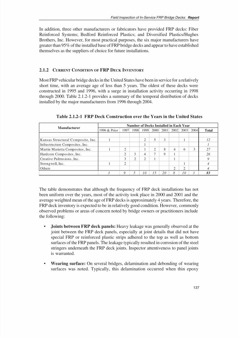
8/8/2019 Inspection of FRP Decks
http://slidepdf.com/reader/full/inspection-of-frp-decks 148/175
In addition, three other manufacturers or fabricators have provided FRP decks: Fiber
Reinforced Systems; Bedford Reinforced Plastics; and Diversified Plastics/Hughes
Brothers, Inc. However, for most practical purposes, the six major manufacturers have
greater than 95% of the installed base of FRP bridge decks and appear to have established
themselves as the suppliers of choice for future installations.
2.1.2 CURRENT CONDITION OF FRP DECK INVENTORY
Most FRP vehicular bridge decks in the United States have been in service for a relatively
short time, with an average age of less than 5 years. The oldest of these decks were
constructed in 1995 and 1996, with a surge in installation activity occurring in 1998
through 2000. Table 2.1.2-1 provides a summary of the temporal distribution of decks
installed by the major manufacturers from 1996 through 2004.
137
Field Inspection of In-Service FRP Bridge Decks: Report
1996 & Prior 1997 1998 1999 2000 2001 2002 2003 2004 Total
Kansas Structural Composite, Inc. 1 2 5 3 1 12
Infrastructure Composites, Inc. 1 1
Martin Marietta Composites , Inc. 1 2 1 2 8 4 6 3 27
Hardcore Composites , Inc. 2 3 4 7 9 1 26
Creative Pultrusions, Inc. 3 2 2 1 1 9
Strongwell, Inc. 1 2 1 4
Others 2 2 4
3 9 5 10 15 20 8 10 3 83
Number of Decks Installed in Each YearManufacturer
Table 2.1.2-1 FRP Deck Construction over the Years in the United States
The table demonstrates that although the frequency of FRP deck installations has not
been uniform over the years, most of the activity took place in 2000 and 2001 and the
average weighted mean of the age of FRP decks is approximately 4 years. Therefore, the
FRP deck inventory is expected to be in relatively good condition. However, commonly
observed problems or areas of concern noted by bridge owners or practitioners include
the following:
• Joints between FRP deck panels: Heavy leakage was generally observed at the
joint between the FRP deck panels, especially at joint details that did not have
special FRP or reinforced plastic strips adhered to the top as well as bottomsurfaces of the FRP panels. The leakage typically resulted in corrosion of the steel
stringers underneath the FRP deck joints. Inspector attentiveness to panel joints
is warranted.
• Wearing surface: On several bridges, delamination and debonding of wearing
surfaces was noted. Typically, this delamination occurred when thin epoxy

8/8/2019 Inspection of FRP Decks
http://slidepdf.com/reader/full/inspection-of-frp-decks 149/175
overlays were used instead of conventional bituminous overlays as the wearing
surface on the decks.
• Haunch supports: There was a concern that the FRP deck may not “sit” solidly
on the haunch, creating a gap between the bottom surface of the FRP deck and
the top surface of haunch, thereby causing impact between the deck and the
haunch due to the passage of vehicles.
• Curbs and parapets: When curbs, and occasionally parapets, are connected to
the deck, the effect on the deck of impact-related damage to the curbs is an issue
of concern. The curbs are typically cast-in-place concrete, with the concrete
extending into the FRP deck core along a narrow strip of the deck for the length
of the parapet or curb.
• Approach joints: Approach joints have been known to be critical areas, often
requiring innovative details to bridge the transition from the approach to the deck.
Where approach joints connect to the FRP deck, the deck edge is stiffened by
filling a narrow strip of the porous core of the deck along the width of theapproach.
• Deck to stringer/beam connectors: Although shear connectors have been used
in many FRP deck installations, the details of these connectors have not yet been
studied in detail. In some installations, steel clips are used to connect the FRP
deck to steel stringers. The general concern regarding clip connections arises due
to lack of understanding on the behavior of these joints in practice. Some
universities are conducting research on the composite action and effective flange
areas of FRP decks and steel stringers. However, current design practice neglects
any composite action between the FRP deck and stringers.
• Delamination of deck components: On some deck installations, there has been
noticeable delamination of the skin sheets from the deck core. This is of
significant concern as delamination of deck components can result in an
exponential reduction in the stiffness of the deck sections.
• Moisture ingress: There have been situations where moisture and water have
seeped into the porous core of the deck cross section. Although the FRP material
used to manufacture decks is resistant to moisture attack, seepage and the
consequent freeze-thaw could result in mechanical damage to the deck, leading
to delamination or cracking of FRP deck components.
In summary, due to its relatively young average age, the FRP bridge deck inventory
seems to be in good condition. However, there exist some material, fabrication, and
detailing issues that are currently affecting the condition of these decks or have the
potential to adversely affect the future condition of these decks. These FRP degradation
mechanisms serve as the foundation for establishing uniform inspection practice.
Field Inspection of In-Service FRP Bridge Decks: Report
138

8/8/2019 Inspection of FRP Decks
http://slidepdf.com/reader/full/inspection-of-frp-decks 150/175
139
Field Inspection of In-Service FRP Bridge Decks: Report
2.1.3 CURRENT INSPECTION PRACTICE
Key observations based on the survey and interview and inspection reports on the current
inspection practice are summarized and presented below:
• No special inspection guidelines currently exist for inspecting FRP decks.
Only New York State DOT has guidelines (i.e., advisory circulars) on use of FRPon bridge structures that specifically identify the special nature of FRP materials
(11). However, the guidelines are generally directed toward use of FRP for repair
and strengthening of concrete structures.
• Some DOTs had requested inspection manuals from the deck
manufacturers; however, the quality and content of the manuals varied
considerably. In addition, many DOTs have not yet formally accepted the
inspection manuals. The research team obtained a more-detailed manual authored
by KSCI for three FRP deck bridges in St. James, Phelps County, in Missouri (12).
• Most DOTs do not perform hands-on inspection. In most states, the currentpractice seems limited to visual inspection.
• The DOTs typically use the same rating system as used for other
conventional bridge components. FRP deck rating is currently based on
subjective evaluation of the deck appearance.
• No guidelines currently exist for rating severity of observed conditions on
the FRP components.
• Most DOTs have performed load testing while some have conducted modal
testing of FRP bridge decks. The testing is usually conducted during the firstyear and is generally not repeated over an extended period past the first year to
2 years of service. The metric used to evaluate the load-testing observations
compares the deflection of the decks during subsequent load tests; no difference
observed during subsequent tests indicates satisfactory performance of the deck.
However, there does not seem to be a uniform method to evaluate and pinpoint
problems if different observations are recorded in subsequent load tests.
• The tap test is used by some DOTs (California, New York, and Ohio), but
many inspection teams are unaware of the methods available and necessary
for inspection of FRP components. Some of the DOTs use the chain-drag
method in addition to tap tests to identify locations of delamination (Californiaand New York).
• Thermography, acoustic methods, and laser shearography have been used
on an experimental basis on some bridges, mostly under University/DOT joint
collaboration programs (University of California San Diego, Virginia Tech, and
8/8/2019 Inspection of FRP Decks
http://slidepdf.com/reader/full/inspection-of-frp-decks 151/175
University of Delaware). It did not appear that any of these methods are being
considered for use in the near future by the DOTs.
• Experimental methods such as impact echo, acoustic emission, radar, and
other methods are being tested at university research facilities for potential
application in the field.
2.2 FINDINGS FROM THE LITERATURE SURVEY
A detailed and thorough literature search was conducted to obtain as much published
information as possible on FRP material and its inspection, with particular emphasis on
literature pertaining to FRP bridge decks. Although substantial literature exists on FRP
bridge decks, most of it documents field and laboratory tests that focus on mechanical
strength and design-related issues (8, 13, and 14). Some researchers, on the other hand,
have conducted research on the durability and environmental stability issues of FRP
material as it relates to civil infrastructure use (1, 7 ).
However, most of the research in design, inspection, damage quantification, residual
strength, and maintenance of FRP materials has been conducted under the auspices of
the defense or aerospace industry organizations. Because FRP materials have been used
in U.S. military and space applications for more than 4 decades, considerable information
on all aspects—from manufacturing to inspection, maintenance, and repair of FRP
components—is available in technical publications issued by the U.S. Department of
Defense (15–20). A summary of literature reviewed during the course of this research
project and its applicability to the objectives of this project is presented in the sections
below.
2.2.1 HISTORICAL PERSPECTIVE ON FRP USE
The initial research into advanced material technology evolved from metallurgical
sciences. The demands of the military and the space industry for cutting-edge
applications in the Cold War era resulted in the development of metal composites in the
mid-1950s. The following decade saw rapid developments in the field of material
engineering, and the development of high modulus boron and graphite filaments in the
1960s initiated an era of non-metallic composite materials (21). Chemical industry giants
such as Union Carbide and DuPont furthered the development and use of composite
materials by designing high-strength, high-modulus carbon, glass, and aramid fibers.
The Department of Defense, the National Aeronautics and Space Administration
(NASA), and the research organizations and private-sector industries that fulfilled their
needs were among the first to conduct detailed research into FRP materials. The
Department of Defense, NASA, and FAA synthesized the applied research conducted by
various organizations and converted it into manuals and circulars to codify and transfer
the best practices for use in military and aerospace products.
Field Inspection of In-Service FRP Bridge Decks: Report
140

8/8/2019 Inspection of FRP Decks
http://slidepdf.com/reader/full/inspection-of-frp-decks 152/175

8/8/2019 Inspection of FRP Decks
http://slidepdf.com/reader/full/inspection-of-frp-decks 153/175
1990s, and the number of such bridges continues to grow as bridge engineers become
comfortable with the material and its performance. However, most of these bridge decks
have been built using proprietary experimental systems and details. The lack of
standardization has been a challenge to bridge engineers, who are accustomed to standard
shapes, sizes, and material properties. In addition, variations in the design and
composition of FRP decks result in unique problems and maintenance issues associated
with each type, thereby complicating the upkeep of these decks. Specific knowledge is
lacking on issues such as durability, post-damage behavior, unraveling of the composite
section, and the effect of environmental factors such as radiation, heat, and moisture.
Furthermore, in the absence of well-defined, readily discernible clues to reveal defects
and deterioration, indirect means such as load testing have been used to ascertain the
adequacy of in-service FRP bridge decks. Bridge owners have undertaken load-testing
programs not only to verify the behavior of FRP decks, but also (due to a lack of better
condition evaluation options) to ensure that the decks’ acceptable behavior will continue
over time (25–28).
However, the load-testing method has three main drawbacks: (1) the decks are designed
with a large factor of safety, so the risk from potential overload is minimal; (2) the design
is typically controlled not by strength requirements but rather by deflection limitations,
so excessive loads could cause failure due to large deformations; and (3) the failure, if it
were to occur, would be non-ductile. Hence in the long-term, visual, or other
complementary indicators also must be evaluated to ensure the safety of the decks.
The design assumptions have been verified through load testing and other research, while
successive tests of in-service decks have demonstrated that the decks have been behaving
as expected. Up to now, and in the absence of better inspection and evaluation methods,
successive load testing has provided an indirect method to assess continued good
performance of the decks.
2.2.3 INSPECTION AND ASSESSMENT OF FRP COMPONENTS
The research on FRP decks has focused mostly on the design, performance, and
durability of this material, with limited energy expended on the study of inspection and
evaluation methods for these decks (9). The survey of the bridge owners and the literature
search revealed that bridge owners have usually requested the deck manufacturer to
provide inspection and maintenance manuals for FRP decks as part of deck installation
projects. In some cases, manufacturers have prepared inspection and maintenance
manuals tailored to the specific bridge details and deck type and submitted them as partof the project deliverables (12). The survey of bridge owners and maintainers showed
that, in many instances, the inspection manuals either were not submitted or were not
accepted by the bridge owners; and in some instances, the manuals were found to be of
limited use for inspection and maintenance of the decks.
Some bridge owners have, however, developed advisory circulars or internal memos that
recognize the special nature of FRP and provide material-specific guidance to help the
practicing engineer, inspector, or maintainer manage the FRP infrastructure. Although
Field Inspection of In-Service FRP Bridge Decks: Report
142
8/8/2019 Inspection of FRP Decks
http://slidepdf.com/reader/full/inspection-of-frp-decks 154/175
143
Field Inspection of In-Service FRP Bridge Decks: Report
most bridge owners did not have such memos or guidance documents, two publications
by New York State DOT were found to be valuable in this study (28, 29).
Unlike the bridge engineering industry, the military and aerospace sectors have used FRP
for more than 4 decades. They have conducted extensive research on the inspection and
maintenance of this material in order to develop practical procedures that will ensure
peak performance of mission-critical FRP components on aircraft and other military
structures. They have produced extensive literature on the inspection and evaluation of
FRP components in the military and aerospace domains. Although there are fundamental
differences in composition, loading, inspection, and evaluation criteria between FRP
used in defense or aerospace applications and that used in bridge applications, the basic
inspection and evaluation philosophy could be adapted to the bridge industry.
Some publications present practical guidelines and insights on inspection of FRP
materials (20, 30–33). Military Handbook 793 (20) addresses various inspection
methods: visual, acoustic, radiography, ultrasound, and so forth (for detailed discussion,
see Appendix 7 ). Inspection and evaluation practices from other non-defense industries
provide additional useful insights and tips on practical inspection procedures that couldbe adopted for inspection of FRP bridge decks (34–37 ).
In addition, state-of-the-art research on inspection and evaluation methods for FRP
material—specifically, FRP civil/structural components—will further the current
knowledge on inspection methods and help to develop innovative methods suited for the
bridge industry. Currently, such research is being conducted in the United Kingdom (38),
at the U.S. Naval Academy (39), and at Virginia Tech (40). Additionally, there are many
other useful publications that present current research on feasible inspection or
evaluation methods for FRP components in civil infrastructures (41–44).
Discussion on the applicability of the various inspection methods, the advantages anddrawbacks of the methods, and adaptability of these methods into current bridge
inspection practice is found in Chapter 3 (also see Appendix 7 ).
2.2.4 DAMAGE THRESHOLDS AND REMAINING LIFE PREDICTION
In the civil industry and for FRP decks in particular, research is lacking in the areas of
damage estimation, damage accumulation, and remaining life prediction. Some research
has been conducted to assess the post-damage behavior of FRP decks (45); research in
the area of long-term performance and damage accumulation has been restricted todurability testing of FRP material (1, 7 ), and fatigue testing of decks (46 ). The research
by Lenett et al. (45) studies the effects of damage on the behavior of FRP sandwich deck
panels. The research finds that damage, especially delamination, distinctly causes change
in the deck stiffness and results in anomalous behavior of the deck. Dutta et al. (46 )
present results from experimental fatigue testing under extreme temperature conditions
of different types of FRP and non-FRP decks subjected to 10 million low-cycle fatigue
through simulated HS-20 vehicular load. The research focuses on the long-term behavior
of FRP decks and shows that behavior of FRP decks is adversely affected by fatigue as

8/8/2019 Inspection of FRP Decks
http://slidepdf.com/reader/full/inspection-of-frp-decks 155/175
well as by higher temperatures. These research studies are limited in their scope,
however, and do not provide in-depth insights into the post-damage strength and
behavior of FRP decks, nor the effect of damage on the serviceability criteria and useful
life of these components. Research on fatigue life of composite beams and civil
components has been conducted by Senne (47 ), Tang et al. (48), and others.
However, extensive physical research exists in the defense and aerospace industries on
damage susceptibility, immediate physical effects of damage, and post-damage behavior
of FRP material and components. Military Handbook 17, Volume 3 (17 ) is a detailed
publication that systematically addresses the issues of damage initiation, damage
quantification, correlation of damage to strength, and the ideas the Department of
Defense adopted to assess damage and its effect on the performance of the FRP
components used in military applications. Other publications provide information on
damage initiation and post-damage behavior of FRP (49–53). Kan (49) presents results
from numerous experimental studies on various composite panels to determine the effect
of impact damage on the strength of the FRP panels as well as the residual strength of
the impacted panels. McGowan and Ambur (50) discuss experimental studies on the
impact damage and residual strength of composite sandwich panels with and without
compression loading. The paper presents correlation between the impact magnitude, the
type of impact, damaged area dimensions (damage diameter), and the residual strength
of the sandwich panel after the impact. Nyman (51) discusses theories and currently used
methods for determining damage thresholds in composite materials and enumerates
inferences from experimental and analytical studies. The experimental and analytical
studies relate to quantification and assessment of damage severity, damage tolerance, and
residual strength of composite material used in the development of the new generation
of Swedish fighter jet JAS39 Gripen. Tomblin et al. (52, 53) meanwhile present a semi-
empirical study of impact damage and fatigue tolerance of sandwich airframe structures
and provide methodologies in which experimental data could be used to develop damage
evaluation criteria.
Extensive studies have also been conducted in the field of analytical assessment and
modeling of damage and damage propagation in FRP material. Case et al. (54, 55)
provide an excellent discussion on practical issues in developing life prediction
techniques for FRP material that are typically used in aerospace applications. There are
other significant studies that focus on analytical issues in modeling damage, damage
propagation, and remaining life of FRP material (56–60).
Although most of the research on damage thresholds and residual strength (i.e.,
remaining life) has been conducted on thin FRP sheet-type or sandwich-type aircraft
materials, the defense and aerospace research provides an excellent starting point forextending or extrapolating the findings and philosophies to FRP decks.
Field Inspection of In-Service FRP Bridge Decks: Report
144
8/8/2019 Inspection of FRP Decks
http://slidepdf.com/reader/full/inspection-of-frp-decks 156/175
145
Field Inspection of In-Service FRP Bridge Decks: Report
2.3 KEY PUBLICATIONS
The following publications from the Department of Defense, the U.S. Army Corps of
Engineers (USACE), and FAA are promising sources for adapting more than 50 years
of industry experience with FRP materials toward bridge engineering applications:
• Composite Materials Handbook, Volumes 1 through 5, are military handbookspublished by the Department of Defense (15–19). Of particular interest is Volume
3, which covers usage, design, and analysis of polymer composite materials. This
detailed and comprehensive handbook covers almost all aspects of composite
behavior and provides practical insight on the damage etiology and accumulated
damage thresholds of FRP materials. In addition, the handbook provides practical
guidelines on identifying defects, damage, and deterioration of FRP components.
• Nondestructive Active Testing Techniques for Structural Composites is another
military handbook published by the Department of Defense (20). This handbook
provides detailed discussion and practical application guidelines for the complete
range of NDT techniques—from visual inspection to the more complex nuclearradiography methods—which could be used on FRP materials. The handbook
also discusses the reliability of the various methods and provides an in-depth
assessment of the techniques, including the correlation of specific NDT methods
to type of defects and type of FRP design.
• Engineering Technical Letter ETL 1110-2-548, “Engineering and Design:
Composite Materials for Civil Engineering Structures,” is published by USACE
(33). The ETL compiles and discusses various issues in the use and upkeep of
composite materials for civil engineering applications. This 60-page document
covers all aspects of FRP material used in civil engineering structures—
manufacturing to durability, quality assurance, and inspection and repair.
• Advisory Circular AC20-76: Maintenance Inspection Notes for Boeing B-
707/720 Series Aircraft and Advisory Circular AC20-107A: Composite Aircraft
Structure, published by FAA (31, 32), provide practical advice and inspection
methods for various FRP components of the Boeing 707 aircraft. These circulars,
and similar circulars and directives for other aircrafts, provide invaluable
practical advice on identifying and appraising damage and defects in structural
components made of FRP materials. The practical aspects of the inspection
techniques and damage detection and appraisal methods identified in these
circulars could easily be adapted for application on bridge structures.
• Structures Design Advisory: FRP Decks and Superstructures, an informative
advisory circular published by New York State DOT (11), alerts bridge designers
and inspectors to the unique characteristics of FRP material and provides
guidance on how to work with this material.

8/8/2019 Inspection of FRP Decks
http://slidepdf.com/reader/full/inspection-of-frp-decks 157/175
• Laboratory and Field Testing of FRP Composite Bridge Decks and FRP-
Reinforced Concrete Bridge for the City of St. James, Phelps County, MO, a
report published by Missouri DOT (12), includes typical details as well as
inspection and maintenance manuals for three FRP bridge decks constructed and
monitored within the scope of the research project.
• “Inspection of FRP Equipment: When and How to Inspect and What to Look
For,” a paper published by TAPPI (37 ), provides some practical guidelines on
inspection of FRP components.
• “Fatigue Performance Evaluation of FRP Composite Bridge Deck Prototypes
Under High and Low Temperatures,” a paper presented at the 82nd Annual
Meeting of the Transportation Research Board in 2003 (46 ), provides
experimental data and inferences from the experimentation to assess the fatigue
characteristics of FRP decks. A Master’s Thesis titled “Fatigue Life of Hybrid
FRP Composite Beams” and published by Virginia Tech (47 ) provides some
excellent data on fatigue characteristics of FRP beams. “Fatigue Model for Fiber-
Reinforced Polymeric Composites in Civil Engineering Applications,” a researchreport published also by Virginia Tech (48), provides useful data, interesting
inferences, and analytic models on the fatigue life of FRP materials used in civil
infrastructure applications.
• “Simulation of Performance and Life Prediction for Composite Laminates:
MRLife12” (55), a software program and its manual published by Virginia Tech,
provides an excellent discussion on developing analytical residual strength or
remaining life models based on experimental data and analytical concepts.
Enhanced Reliability Prediction Methodology for Impact Damaged Composite
Structures, published by FAA (49), provides data on strength reduction due to
various types of damages on various types of FRP materials. The data from thisresearch could be useful to devise a statistical semi-empirical method that other
industries could use to gage the severity of damage and its likely effect on the
material’s post-damage performance.
Field Inspection of In-Service FRP Bridge Decks: Report
146

8/8/2019 Inspection of FRP Decks
http://slidepdf.com/reader/full/inspection-of-frp-decks 158/175
8/8/2019 Inspection of FRP Decks
http://slidepdf.com/reader/full/inspection-of-frp-decks 159/175
core–to–face sheet connections while in pultruded sections, the critical locations
could be at joints between each pultruded subcomponent. In addition, the
corrugated core in some sandwich-panel decks is bonded to the face sheets along
thin edges, creating potentially weak areas that can easily separate due to poor
adhesion or load-deflection effects.
• Potential for superfluous changes leading to development of newer deck
designs: Without established guidelines, designers and manufacturers have the
freedom to vary any aspect of FRP material, section, or manufacturing method.
This can result in development of superfluous variations in deck type, each
slightly different from the other and each with different performance and
behavior patterns. This practice could result in unnecessarily large variety of
decks without any real benefit in terms of better design or performance, leading
to difficulty in maintaining or managing such deck inventory.
• Difficulty in expeditiously assimilating and distributing critical information
about new design should be anticipated: Although it is possible to catalog
critical areas and peculiarities of each given deck, each new deck type introducedinto the bridge inventory will require careful evaluation and study by the bridge
owner to identify the critical details and vulnerable areas in the new deck type.
In addition, this ever-changing information will have to be collected, analyzed,
composed, and disseminated at regular intervals to practicing engineers,
inspectors, and maintainers in order to keep them up-to-date on the vulnerabilities
and issues of each deck type.
• Inadequate testing and performance assessment: The research team feels that
the ease with which deck types can be changed may lead to creation and
installation of future FRP decks without the rigorous testing and assessment that
is now common. Such inadequate testing and assessment could result ininstallation of decks whose behavior is not clearly understood and whose critical
details or vulnerable locations are not clearly identified, potentially causing
serviceability and safety problems in the future.
3.2 ISSUES WITH CURRENT INSPECTION PRACTICE
The current inspection practice ranges from no inspection of the FRP deck to detailed
inspection that includes visual inspection, tap testing, load testing, modal testing, and
thermography.
Among participants in the bridge owner group, the survey found limited awareness of
the FRP decks’ uniqueness or their need for special methods and activities for inspection
and maintenance. Some survey participants were unaware of the need to check for simple
visual clues such as discoloration or cracking or acoustic clues such as hollow sounds to
detect delamination. From the survey, it appears that most personnel involved with the
design of FRP decks appreciated the need for addressing special inspection and
Field Inspection of In-Service FRP Bridge Decks: Report
148

8/8/2019 Inspection of FRP Decks
http://slidepdf.com/reader/full/inspection-of-frp-decks 160/175
149
Field Inspection of In-Service FRP Bridge Decks: Report
maintenance issues regarding such decks; however, personnel not involved in the design
and those responsible only for deck inspection or maintenance seemed to consider these
decks similar to conventional concrete decks in their inspection and repair needs. Very
few of the survey participants seemed to employ FRP deck–specific inspection methods
while inspecting their FRP deck inventories.
Most survey participants from the academic and consulting group and some from the
owner group were aware of the FRP decks’ uniqueness and their need for special
methods for inspection, assessment, and maintenance. Many among these survey
participants were aware of more-detailed inspection methods such as ultrasonic,
radiographic, and thermographic methods. It was also discovered that some of these
nonstandard techniques, such as ultrasonic and thermographic methods, were being
evaluated through joint owner-academic research projects.
Based on these findings, the research team sees a clear and definite need for education
and training of bridge inspectors and maintainers as to the unique nature of FRP decks
and methods to inspect and evaluate these decks.
3.3 CLASSIFICATION OF SIGNIFICANT DETAILS
Given many types of bridge decks—each with distinct material characteristics,
fabricating methods, cross-sectional details, and performance characteristics—the
research team recommends organizing the inspection instructions by the deck or
manufacturer type. Because critical areas and inspection methods differ for each deck
type, it makes practical sense to organize the data by deck types. Doing so serves two
purposes: (1) it makes it easy for inspectors to select an appropriate checklist of details
to inspect and (2) it allows inspectors to choose appropriate inspection methods andevaluation criteria.
For each deck type, an ideal method to organize the data for inspection and evaluation
of the FRP decks is by dividing the deck details into two major categories: those
associated with the deck cross section and those associated with bridge geometry and
connections.
• Category 1: Details within the deck cross section: Significant details in this
category include those that are associated with cross-section design, material,
manufacturing, and fabrication of deck panels. The significant details within this
category generally depend on the material components, manufacturing andfabrication process, and cross-section composition of the deck.
• Category 2: External details and connections: In this category, details related
to entities external to the deck cross section are included. Some of these entities
include wearing surfaces, connections between deck panels, connection of deck
panels to the superstructure and substructure, and connection details of the
parapets and railings to the deck or other superstructure elements. The significant
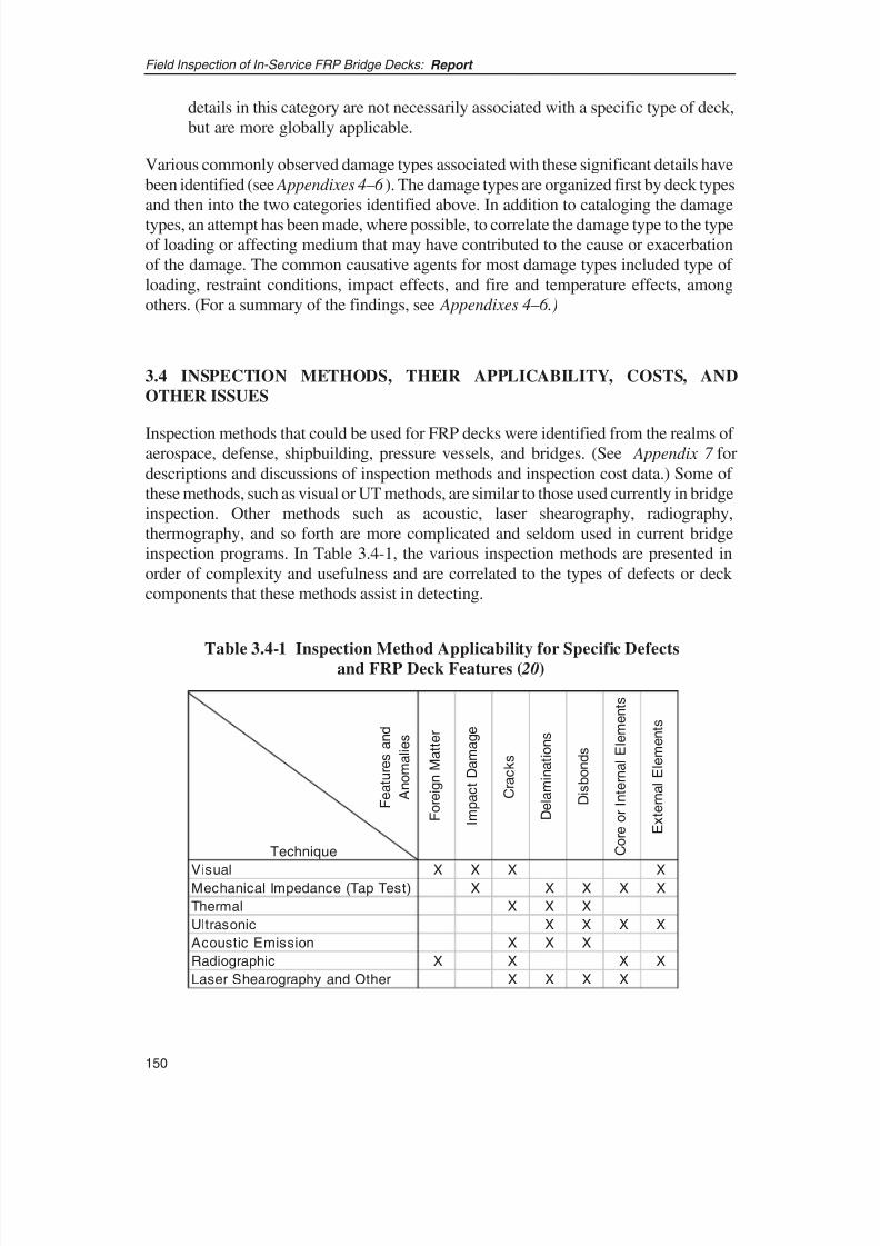
8/8/2019 Inspection of FRP Decks
http://slidepdf.com/reader/full/inspection-of-frp-decks 161/175
details in this category are not necessarily associated with a specific type of deck,
but are more globally applicable.
Various commonly observed damage types associated with these significant details have
been identified (see Appendixes 4–6 ). The damage types are organized first by deck types
and then into the two categories identified above. In addition to cataloging the damage
types, an attempt has been made, where possible, to correlate the damage type to the type
of loading or affecting medium that may have contributed to the cause or exacerbation
of the damage. The common causative agents for most damage types included type of
loading, restraint conditions, impact effects, and fire and temperature effects, among
others. (For a summary of the findings, see Appendixes 4–6.)
3.4 INSPECTION METHODS, THEIR APPLICABILITY, COSTS, AND
OTHER ISSUES
Inspection methods that could be used for FRP decks were identified from the realms of aerospace, defense, shipbuilding, pressure vessels, and bridges. (See Appendix 7 for
descriptions and discussions of inspection methods and inspection cost data.) Some of
these methods, such as visual or UT methods, are similar to those used currently in bridge
inspection. Other methods such as acoustic, laser shearography, radiography,
thermography, and so forth are more complicated and seldom used in current bridge
inspection programs. In Table 3.4-1, the various inspection methods are presented in
order of complexity and usefulness and are correlated to the types of defects or deck
components that these methods assist in detecting.
Field Inspection of In-Service FRP Bridge Decks: Report
150
Technique
Visual X X X XMechanical Impedance (Tap Test) X X X X X
Thermal X X X
Ultrasonic X X X X
Acoustic Emission X X X
Radiographic X X X X
Laser Shearography and Other X X X X
F e a t u r e s a n d
A n o m a l i e s
E x t e r n a l E l e m e n t s
I m p a c t D a m a g e
F o r e i g n M a t t e r
C o r e o r I n t e r n a l E l e m e n t s
D i s b o n d s
D e l a m i n a t i o n s
C r a c k s
Table 3.4-1 Inspection Method Applicability for Specific Defectsand FRP Deck Features ( 20)

8/8/2019 Inspection of FRP Decks
http://slidepdf.com/reader/full/inspection-of-frp-decks 162/175
151
Field Inspection of In-Service FRP Bridge Decks: Report
The visual method is by far the most important and simplest technique for inspection of
FRP decks. Even in the aerospace and defense industries, inspectors rely on the visual
technique for detecting in-service problems. Visual inspection allows the inspector to
rapidly detect gross imperfections or defects such as cracks, delamination, or impact
damage. Visual inspection often can aid in detecting other imperfections such as porous
adhesive fillets, lack of filleting, lack of adhesive, edge voids, discoloration, deformation,
and other imperfections. To a trained inspector, the visual technique provides immediate
clues, and this method serves as the mechanism for identifying areas that should be
inspected through other more-detailed and complex methods. Although this technique is
operator-interpretive, it is of such significant value that the inspectors should be trained
to know what they are looking for and what any variation might mean to the strength and
reliability of the component. The visual method, however, has two drawbacks: (1) it does
not lend itself to quantifying the extent of damage and (2) components within another
component or not directly visible can not be inspected by this method.
Tap testing is another excellent and easy method for inspecting FRP decks. The tap test
allows the inspector to notice changes in sounds emitted while tapping FRP surfaces.
Although this method lends itself more readily to inspection of sandwich panels, it can
nevertheless be used on pultruded sections, albeit with lesser degree of effectiveness in
detecting delaminations or debonds. However, most common problems on FRP decks
can be identified by using the tap-test method in conjunction with the visual technique.
Neither of these techniques requires any specialized equipment, and both are easy to
incorporate into a bridge owner’s inspection program through training in inspection of
FRP components. On the other hand, some of the other techniques listed above are much
more complex, are significantly more costly and time-consuming, and require special
expertise in conducting the tests and in interpreting the results. Except for thermography,
most of the specialized methods are useful only for inspecting small areas due to cost and
operational reasons. Therefore, these methods are more practical for detailed assessment
of potentially damaged or defective areas that have already been identified by either the
visual or the tap-test methods.
Of the various advanced methods, thermography and UT appear to be most practical in
terms of their applicability and adoptability in a bridge owner’s inspection program.
Bridge engineers and inspectors already familiar with UT equipment and technique
would find it easy to adapt this method for use on FRP decks. The thermography method
also could be readily adopted into an inspection program because it is somewhat easier
to use, does not require very expensive equipment, and provides output that can be
visually analyzed. The other techniques, such as radiography and shearography, are more
costly and often require expensive specialized equipment and considerable training tooperate the equipment and interpret the results. Hence, these other techniques, although
useful and applicable, appear less likely to be incorporated into the current bridge
inspection programs.
8/8/2019 Inspection of FRP Decks
http://slidepdf.com/reader/full/inspection-of-frp-decks 163/175
3.5 DETAILS AND DESIGNS THAT WILL BE DIFFICULT TO INSPECT
As discussed in the previous section, numerous methods are available to inspect critical
details and detect defects or damage in FRP bridge decks. The research team feels that
visual and tap-test methods can provide satisfactory results in detecting defects and
damages at most locations on FRP decks. Specific areas identified by the visual or tap test
techniques that require further in-depth investigation can then be inspected using
advanced techniques such as thermography, radiography, or UT. Although some of these
methods detect damage that generally cannot be detected by visual or tap-test methods,
they cannot necessarily detect damage in every location on the deck. In some areas of the
deck, none of the current methods is effective in detecting and assessing the extent of
damage.
Based on evaluation of all the in-service FRP decks, it appears that some Category 1
details, such as the core or the web elements, are the most difficult details to inspect. Due
to the nature of the deck cross section and the layout of deck sub-components, the region
of deck cross section between the top and bottom surfaces or face sheets is not visible for
visual inspection. Although the tap test can detect damage such as delaminations ordisbonds, this detection is limited to areas close to the top and bottom surfaces of the
decks; in most cases, even the top surface of the deck is not accessible due to the
presence of thick overlays.
Among the types of defects, disbonds between the core and the top face sheet in
sandwich-type decks are probably the most difficult to detect. Based on findings on the
Salem Avenue Bridge, it appears that the core–to–face sheet connection in sandwich-
panel decks is vulnerable to disbond due to the small edge area along which the core
section is adhered to the face sheets. Even advanced methods like radiography are
probably not effective for detecting this defect unless the X-rays are taken in the
horizontal plane and in proximity to the defect. Any defect in the core that would bevisible to a radiograph in the plan view would therefore be easier to detect than a defect
that would be visible in a cross-sectional view. In the case of core–to–top face sheet
disbond, modal testing methods or other methods such as impact echo or impulse
response may provide a solution in detecting such damages.
In pultruded decks, web and flange (top and bottom surfaces) are created concurrently
in the pultrusion process, and the sections do not have any discontinuity between the core
elements (or web elements) and the flanges. Also, since pultrusion is an automated
process, the quality of the pultruded product is likely to be uniform and consistent as
compared with sandwich construction in which semi-automatic or manual processes
typically are used. Thicker elements and robust sections in this type of deck, however,make it less responsive to tap tests. In addition, this type of deck has similar inspectability
issues as the sandwich decks except that the likelihood of defects in this type of deck
could be better controlled as compared with sandwich decks.
Although there are some significant details in FRP decks that seem to create
inspectability issues, the research team feels the existence of any such damage or defect
Field Inspection of In-Service FRP Bridge Decks: Report
152

8/8/2019 Inspection of FRP Decks
http://slidepdf.com/reader/full/inspection-of-frp-decks 164/175
153
Field Inspection of In-Service FRP Bridge Decks: Report
would lead to other signs such as larger deflections, discolorations, dimpling, stretch
marks, and so forth that would alert the inspector to the existence of problems. (Further
discussion on significant details, inspection methods, and difficult-to-inspect areas of
each of the major deck types is presented in Appendixes 4 and 7 .)
3.6 INFERRING AND INTERPRETING INSPECTION RESULTS
Inferring and interpreting inspection results is one of the most important aspects of
productively using inspection data to ensure safety and serviceability of inspected
components. In the case of FRP bridge decks, once the damage or defects are identified
and categorized, they will have to be evaluated and assessed based on some form of
uniform rating system. The research team believes that for Category 2 significant
details—which include connections, overlays, joints, and so forth—of the assessment
could be made using a hybrid method that draws on guidelines used for conventional
bridge components combined with those for FRP elements.
However, for Category 1 significant details—that is, details internal or intrinsic to the
FRP deck cross section—of a system will have to be developed that will correlate
observed damage to reduction in remaining life of the components. Although it is
difficult to quantify the somewhat subjective inspection data from visual observations or
acoustic tests, the aerospace and defense industries have developed methods to quantify
some of these results. Based on the type of defect and magnitude of damage, the severity
and potential for failure due to the damage are evaluated using a uniform scale in military
and aerospace applications. This approach to evaluating damage on composite aircraft
structure and components is based on extensive experimental and theoretical studies. For
example, one of the charts developed from these studies (17, Figure 7.3.2 [a]) is
reproduced below in Figure 3.6-1. As observed in Figure 3.6-1, the chart allows one tocorrelate the extent of damage (diameter of hole or extent of delamination, etc.) to the
reduction in load-carrying capacity of the components, thereby allowing for a systematic
evaluation of damage with respect to the reduction in strength.
Although the chart is designed for aircraft structures, it shows that a workable systematic
approach does exist for assessment of FRP field inspection data. It should be noted,
however, that these charts in the military handbooks and other aerospace references have
been developed from more than 50 years of research, testing, and development, and it is
unlikely that similar charts could be developed for the bridge engineering industry within
the scope of this project. In addition, aircraft structures are inspected at very high
frequency, typically before and after each flight. However, it is possible to borrow theidea from the defense industry to establish a long-term goal of developing similar charts
for the bridge industry.

8/8/2019 Inspection of FRP Decks
http://slidepdf.com/reader/full/inspection-of-frp-decks 165/175
The research team developed a semi-empirical method that would assist an inspector in
evaluating and assessing the damage and deterioration based on some uniform or
standard scale. This correlation of damage or deterioration to remaining life either could
be set arbitrarily or could be devised using some of the test data from aerospace
applications. For example, for a specific type of deck, the extent of damage quantified
by the delaminated area could be related to specific reduction in strength. The scale wasset such that at one end, for no delamination, there would be no reduction in carrying
capacity of the deck while a delamination diameter of twice the deck thickness or half
the clear span of the deck could be attributed to loss of, say, 50% of the strength.
Field Inspection of In-Service FRP Bridge Decks: Report
154
Figure 3.6-1 Damage versus Strength Reduction (17 , Figure 7.3.2[a]).

8/8/2019 Inspection of FRP Decks
http://slidepdf.com/reader/full/inspection-of-frp-decks 166/175
155
Field Inspection of In-Service FRP Bridge Decks: Report
CHAPTER 4
CONCLUSIONS
The research conducted under NCHRP Project 10-64 has developed recommended
uniform guidelines for inspection and condition evaluation of in-service FRP bridge
decks and developed and implemented the pilot session of a course to train bridge
inspectors on the methods of inspecting these bridge decks. The study is based on current
state-of-the-art knowledge on FRP material and decks; ongoing research; experiences of
bridge owners, maintainers, fabricators, and designers; knowledge from the defense and
aerospace industries; and the state of current practice in the use and assessment of this
material in the United States and in other countries.
Information in support of this research was gathered primarily through two sources—
published literature and the unpublished accounts and experiences of owners, inspectors,
practicing engineers, researchers, and others associated with FRP material in general and
FRP decks in particular. The collected information was used in conjunction with the
experiences of the research team members to develop practical insights into the current
state of inspection practice, inspection requirements, and inspection and assessment
methods for FRP bridge decks.
Based on the research, the key conclusions made by the research team are summarized
below:
• Due to the relatively young age of the FRP bridge deck inventory, the decks
are currently in good condition in general. Many of these bridge decks have
been instrumented and monitored, and most have undergone load tests at regular
intervals for 2 or more years after construction. However, on some isolated bridge
decks, problems have been observed, prompting extensive evaluation and
remedial activities.
• Awareness regarding the unique nature of FRP decks is lacking when
compared with decks and components made of conventional construction
materials. Therefore, the need for FRP-specific inspection requirementscontinues.
8/8/2019 Inspection of FRP Decks
http://slidepdf.com/reader/full/inspection-of-frp-decks 167/175
• In addition to the inspection manual, future development of analytical rating
and maintenance guidelines for FRP decks and components is warranted.
• The many commercial variants of FRP bridge deck types in service today
make it more challenging to design, build and maintain FRP deck types.
Because technical innovation and competitiveness will continue, new design and
fabrication and construction methods will proliferate, perhaps causing some of
the existing systems to become obsolete. Therefore, the research team urges that
AASHTO, state highway departments, and the funding agencies maintain efforts
like this one to create and communicate relevant guidelines and other information
related to design, manufacture, construction, inspection, and maintenance of FRP
bridge decks.
• The research team has identified crucial performance details for each major
type of FRP deck design. These details have been classified into two categories,
one specific to the details within the deck sections and the other containing details
associated with connections and other locations external to the deck cross section.
The visual and tap-test methods are presently the most suitable techniques forinspection of FRP decks. Other advanced methods should be used to perform
more-detailed investigations and structural evaluations after specific areas of
interest are identified through visual or tap-test techniques.
• The research team found that limited data were available for quantifying the
severity and criticality of defects. Most of data and research in this area have
been restricted to military and aerospace research with almost no systematic
studies conducted for FRP bridge decks. The research team developed a semi-
empirical scale for assessing the severity of defects and damage in FRP decks by
using experiences from other industries. The research team compiled this
knowledge base on inspection of FRP deck while performing Tasks 1 through 5and used it to develop the inspection manual and training course.
• In addition to those discussed above, the research team has discovered
knowledge gaps in the state-of-the-art research. The research team feels that
the variety of deck designs has contributed significantly to the creation of these
knowledge gaps. Specific research is limited in the following areas and needs to
be initiated:
– Fatigue, durability, and the effect of environmental loads on FRP decks.
– Damage initiation and propagation in FRP decks. This type of data isparticularly important for assessing deck sections near curbs, railings,
and other connection areas where there is high probability for impact and
damage.
– The post-damage behavior, remaining strength, and remaining life of FRP
decks. Although such studies have been conducted in the defense and
Field Inspection of In-Service FRP Bridge Decks: Report
156

8/8/2019 Inspection of FRP Decks
http://slidepdf.com/reader/full/inspection-of-frp-decks 168/175
157
Field Inspection of In-Service FRP Bridge Decks: Report
aerospace industries, the studies have not yet been extended to civil
engineering applications.
– Composite action or the effect of composite action on FRP decks. Many
FRP decks have been constructed with deck-to-stringer connection
details that foster composite action and therefore should be studied to
understand the effect of composite action on the FRP deck.

8/8/2019 Inspection of FRP Decks
http://slidepdf.com/reader/full/inspection-of-frp-decks 169/175
REFERENCES FOR REPORT
1. Dumlao. C., et al. “Demonstration Low-cost Modular Composite HighwayBridge,” Proceedings of the First International Conference on Composites in
Infrastructure, University of Arizona, 1996.
2. Griffiths, J.R. “Plastic Highway Bridges.” Cambridge Scientific Abstracts,November 2000.
3. Howdyshell, P.A., et al. Development and Demonstration of Advanced Design
Composite Structural Components, Construction Productivity AdvancementResearch Program, USACERL Technical Report 98/99, U.S. Army Corps of
Engineers, Washington, DC, July 1998.
4. Winkelman, T.J. Fiberglass Reinforced Polymer Composite Bridge Deck
Construction in Illinois, Construction Report/Physical Testing Report 145,Illinois DOT, September 2002.
5. Rizkalla, S.H., and Fam, A.Z. “Experimental Testing of DuraSpan® Fiber-Reinforced Polymer (FRP) Bridge Deck,” September 2000.
6. Canning, L., and Hodgson, J. “Analysis, Design, and Optimization of anAdvanced Composite Bridge Deck,” ASSET Program, European Union, 2002.
7. Karbhari, V.M., Chin, J.W., and Reynaud, D. “Critical Gaps in Durability Datafor FRP Composites in Civil Infrastructure,” SAMPE Symposium and
Exhibition, Long Beach, CA, 2000.
8. Karbhari, V.M. “HITEC Evaluation Plan for FRP Composite Bridge Decks:
Final Version,” HITEC 2001.
9. Mertz, D.R., Chajes, M.J., Gillespie Jr., J.W., Sabol, S.A., Hawkins, N.M.,Wilkins, A., and Deen, T.B. NCHRP Report 503: Application of Fiber
Reinforced Polymer Composites to the Highway Infrastructure, Transportation
Research Board of the National Academies, Washington, DC, 2003.
10. Federal Highway Administration. Safety Inspection of In-Service Bridges:
Participant Notebook: Volume 1, Publication FHWA HI-94-031, May 1994.
11. Structures Design Advisory: FRP Decks and Superstructures, advisory circular,New York State DOT, 2002.
12. Nystrom, H., Watkins, S., Stone, D., and Nanni, A. Laboratory and Field Testing
of FRP Composite Bridge Decks and FRP-Reinforced Concrete Bridge for City
Field Inspection of In-Service FRP Bridge Decks: Report
158

8/8/2019 Inspection of FRP Decks
http://slidepdf.com/reader/full/inspection-of-frp-decks 170/175
159
Field Inspection of In-Service FRP Bridge Decks: Report
of St. James, Phelps County, MO, Missouri DOT Report RDT02-012, Missouri
DOT, 2002.
13. Zhou, A. “Stiffness and Strength of Fiber Reinforced Polymer Composite Bridge
Deck Systems,” Dissertation for Ph.D. in Engineering Mechanics, Virginia
Polytechnic Institute and State University, 2002.
14. Davalos, J.D., Barbero, E.J., and Qiao P. “Step-by-Step Engineering Design
Equations for Fiber-Reinforced Plastic Beams on Transportation Structures,”
West Virginia DOT, 1999.
15. U.S. Department of Defense. Composite Materials Handbook , Volume 1:
Polymer Matrix Composites: Guidelines for Characterization of Structural
Materials, Military Handbook MIL-HDBK-17-1F, Washington, DC, June 2002.
16. U.S. Department of Defense. Composite Materials Handbook, Volume 2:
Polymer Matrix Composites: Material Properties, Military Handbook MIL-
HDBK-17-2F, Washington, DC, June 2002.
17. U.S. Department of Defense. Composite Materials Handbook, Volume 3:
Polymer Matrix Composites: Materials Usage, Design, and Analysis, Military
Handbook MIL-HDBK-17-3F, Washington, DC, June 2002.
18. U.S. Department of Defense. Composite Materials Handbook, Volume 4: Metal
Matrix Composites, Military Handbook MIL-HDBK-17-4A, Washington, DC,
June 2002.
19. U.S. Department of Defense. Composite Materials Handbook, Volume 5:
Ceramic Matrix Composites, Military Handbook MIL-HDBK-17-5,Washington, DC, June 2002.
20. U.S. Department of Defense. Nondestructive Active Testing Techniques for
Structural Composites, Military Handbook MIL-HDBK-793(AR), Washington,
DC, November 1989.
21. Scala, E.P. “A Brief History of Composites in the U.S.—The Dream and the
Success.” JOM: The Member Journal of the Minerals, Metals & Materials
Society, 48 (2), 1996, pp. 45–48.
22. Tang, B. “Fiber Reinforced Polymer Composites Applications in the U.S.,”
Proceedings of the First Korea/U.S.A. Road Workshop, Federal HighwayAdministration, January, 1997.
23. Tang, B., and Podolny, Jr., W. “A Successful Beginning for Fiber Reinforced
Polymer (FRP) Composite Materials in Bridge Applications.” Proceeding of
FHWA International Conference on Corrosion and Rehabilitation of Reinforced
Concrete Structures, Orlando, FL, December 1998.
8/8/2019 Inspection of FRP Decks
http://slidepdf.com/reader/full/inspection-of-frp-decks 171/175
24. Hooks, J., et al. FHWA Study Tour for Advanced Composites in Bridges in
Europe and Japan. Federal Highway Administration, December 1997.
25. Kumar, P., Chandrashekhara, K., and Nanni, A. “Testing and Evaluation of
Components for a Composite Bridge Deck,” Journal of Reinforced Plastics and
Composites, 2001.
26. Chiewanichakorn, M., Aref, A., and Alampalli, S. “An Analytical Study of an
FRP deck on a Truss Bridge,” State University of New York at Buffalo, 2001.
27. Alampalli, S., and Kunin, J. Load Testing of an FRP Bridge Deck on a Truss
Bridge, REPORT FHWA/NY/SR-01/137, New York State DOT, 2001.
28. Alampalli, S., O’Connor, J., and Yannotti, A. P. Design, Fabrication,
Construction, and Testing of an FRP Superstructure, REPORT FHWA/NY/SR-
00/134, New York State DOT, 2000.
29. Structures Design Advisory: Guidance for FRP Repair and Strengthening of Concrete Substructures,” advisory circular, New York State DOT, 2002.
30. U.S. Department of Defense. Glass Reinforced Plastics Preventive Maintenance
and Repair. Military Handbook MIL-HDBK-803, Washington, DC, April 1990.
31. Federal Aviation Administration. Maintenance Inspection Notes for Boeing B-
707/720 Series Aircraft, FAA AC20-76, Washington, DC, October 1971.
32. Federal Aviation Administration. Composite Aircraft Structure, FAA AC20-
107A, Washington, DC, April 1984.
33. U.S. Army Corps of Engineers. Engineering and Design: Composite Materials
for Civil Engineering Structures, ETL 1110-2-548, Washington, DC, March
1997.
34. “Project 129-99 Self-Help Guide for In-Service Inspection of FRP Equipment
and Piping Communications,” Materials Technology Institute of Chemical
Process Industry, Inc., 2001.
35. Johnson, D.B., Newhouse, N.L., Baldwin, D.D., and Lo, K.H. “Codes and
Standards for Composite Tanks and Vessels: A General Discussion,” Third
International Conference on Composite Materials for Offshore Operations,
Houston, TX, 2000.
36. Navigation and Vessel Inspection Circular No. 0-97 , NVIC 0-97, COMDTPUB
P16700.4, U.S. Department of Defense, 1996.
37. Cowley, T. W. “Inspection of FRP Equipment: When and How to Inspect and
What to Look For,” TAPPI 1991 Engineering Conference, Dow Chemical
Company, 1991.
Field Inspection of In-Service FRP Bridge Decks: Report
160
8/8/2019 Inspection of FRP Decks
http://slidepdf.com/reader/full/inspection-of-frp-decks 172/175
161
Field Inspection of In-Service FRP Bridge Decks: Report
38. Sadka, B. Performance Assessment of FRP Decks, research report, U.K.
Highway Research Agency, 2002.
39. Ratcliffe, C.P. Crane, R.M., Gillespie, J.W., and Heider, D. “Bridge Evaluation
Workshop: Field Load Testing and Long-Term Monitoring—New Technologies
(SIDER),” Bridge Evaluation Workshop Presentation, U.S. Naval Academy,
2002.
40. Duke, J.C., Case, S., and Lesko, J.J., “NDE of FRP Decks and Beams,”
Presentation at the 29th Annual Review of QNDE 2002, Virginia Polytechnic
Institute and State University, 2002.
41. Miceli M., Pitkin, L., Horne, M.R., and Duke Jr., J.C. “Health Monitoring of
FRP Bridge Decks,” Presentation at SPIE NDE For Health Monitoring, 2001.
42. Turner, M.K., Harries, K.A., and Petrou, M.F. “In-situ Structural Evaluation of
GFRP Bridge Deck System,” Paper presented at the 82nd Annual Meeting of the
Transportation Research Board, Washington, DC, 2003.
43. Dillenz, A., Busse, G., and Wu, D. Ultrasound Lockin Thermography:
Feasibilities and Limitations, SPIE, 1999.
44. Lever, J.M., and Hamilton III, J.R. “Nondestructive Evaluation of Carbon Fiber-
Reinforced Polymer-Concrete Bond Using Infrared Thermography,” ACI
Materials Journal, 2003.
45. Lenett, M.S., Helmicki, A.J., and Hunt, V.J. “Multi-Reference Impact Testing of
FRP Bridge Deck Material,” Proceedings of the 18th International Modal
Analysis Conference, San Antonio, TX, 2000.
46. Dutta, P.K., Kwon, S., and Lopez-Anido, R. “Fatigue Performance Evaluation
of FRP Composite Bridge Deck Prototypes Under High and Low Temperatures,”
Paper presented at the 82nd Annual Meeting of the Transportation Research
Board, Washington, DC, 2003.
47. Senne, J.L. “Fatigue Life of Hybrid FRP Composite Beams,” M.S. Thesis,
Virginia Polytechnic Institute and State University, 2000.
48. Tang, H., Nguyen, T., Chuang, T., and Lesko, J. “Fatigue Model for Fiber-
Reinforced Polymeric Composites in Civil Engineering Applications,” Virginia
Polytechnic Institute and State University, 1997.
49. Kan, H.P. Enhanced Reliability Prediction Methodology for Impact Damaged
Composite Structures, Report DOT/FAA/AR-97/79, Federal Aviation
Administration, Washington DC, 1998.
8/8/2019 Inspection of FRP Decks
http://slidepdf.com/reader/full/inspection-of-frp-decks 173/175
50. McGowan, D.M., and Ambur, D.R. “Damage Characteristics and Residual
Strength of Composite Sandwich Panels Impacted with and without a
Compression Loading,” Paper presented the 39th AIAA/ASME/ASCE/AHS/ASC
Structures, Structural Dynamics and Materials Conference, American Institute of
Aeronautics and Astronautics, 1998.
51. Nyman, T. Fatigue and Residual Strength of Composite Aircraft Structures,
Report 99-26, Department of Aeronautics, Kungliga Tekniska Hogskolan (Royal
Institute of Technology), SE-10044 Stockholm, Sweden, 1999.
52. Tomblin, J., Lacy, T., Smith, B., and Hooper, S. Review of Damage Tolerance
for Composite Sandwich Airframe Structures, DOT/FAA/AR-99/49, Federal
Aviation Administration, Washington DC, 1999.
53. Tomblin, J., and Raju, S. “Damage Tolerance of Composite Sandwich Airframe
Structures,” Wichita State University, 2002.
54. Case, S., South, J., Duthoit, J., and Reifsnider, K. “Life Prediction Techniquesfor Composite Materials,” presentation at Virginia Polytechnic Institute and
State University, 1999.
55. Case, S., and Reifsnider, K. “Simulation of Performance and Life Prediction for
Composite Laminates: MRLife12,” Software Program Manual, Virginia
Polytechnic Institute and State University, 1999.
56. Swartz, D., and Ilcewicz, L. “Fatigue and Damage Tolerance Perspectives for
Composite Aircraft Structures,” Presented at the FAA/DOD/NASA Aging
Aircraft Conference, 2002.
57. Sarkani, S., and Michaelov, G. “Nonlinear Damage Accumulation in Stochastic
Fatigue of FRP Laminates,” Presented at the 8th ASCE Specialty Conference on
Probabilistic Mechanics and Structural Reliability, ASCE, 2000.
58. Jolma, P. “Residual Strength of Laterally Loaded CFRP/PVC Sandwich Panels
with Impact Damage,” Paper based on the Nordsandwich-project, Report
BVAL36-011116, Technical Research Centre of Finland, Espoo, 2001.
59. Barbero, E. J., and De Vito, L. “A Constitutive Model for Elastic Damage in
Fiber Reinforced PMC Laminate,” Research report, NSF Research Grant
CMS-9612162, National Science Foundation, 2000.
60. Park, S.W., Veazie, D.R., and Zhou, M. Post-Impact Aging of FRP Composite
Laminates in the Marine Environment, U.S. Department of Defense, Office of
Naval Research, 2000.
Field Inspection of In-Service FRP Bridge Decks: Report
162

8/8/2019 Inspection of FRP Decks
http://slidepdf.com/reader/full/inspection-of-frp-decks 174/175
163
Field Inspection of In-Service FRP Bridge Decks: Report
APPENDIXES FOR REPORT
The following appendixes are not published herein but are available online at
trb.org/news/blurb_detail.asp?id=5905:
• Appendix 1: List of Reviewed Literature
• Appendix 2: Survey Questionnaire
• Appendix 3: Survey Results
• Appendix 4: Summary of Installed FRP Decks and Their Damage Inspection
• Appendix 5: Connection Details and Critical Inspection Points
• Appendix 6: Damage Types
• Appendix 7: Inspection Methods
• Appendix 8: Manual for Inspection of In-Service FRP Bridge Decks
• Appendix 9: Assessment of Likelihood of Damage Progression
• Appendix 10: Training Guide and Presentation for Manual for Inspection of In-
Service FRP Bridge Decks
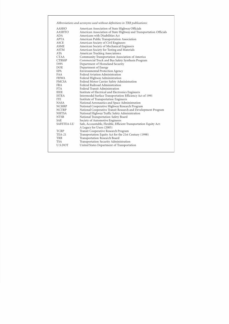
8/8/2019 Inspection of FRP Decks
http://slidepdf.com/reader/full/inspection-of-frp-decks 175/175
Abbreviations and acronyms used without definitions in TRB publications:
AASHO American Association of State Highway OfficialsAASHTO American Association of State Highway and Transportation OfficialsADA Americans with Disabilities ActAPTA American Public Transportation AssociationASCE American Society of Civil EngineersASME American Society of Mechanical EngineersASTM American Society for Testing and MaterialsATA American Trucking Associations
CTAA Community Transportation Association of AmericaCTBSSP Commercial Truck and Bus Safety Synthesis ProgramDHS Department of Homeland Security DOE Department of Energy EPA Environmental Protection Agency FAA Federal Aviation AdministrationFHWA Federal Highway AdministrationFMCSA Federal Motor Carrier Safety AdministrationFRA Federal Railroad AdministrationFTA Federal Transit AdministrationIEEE Institute of Electrical and Electronics EngineersISTEA Intermodal Surface Transportation Efficiency Act of 1991ITE Institute of Transportation EngineersNASA National Aeronautics and Space AdministrationNCHRP National Cooperative Highway Research ProgramNCTRP National Cooperative Transit Research and Development Program
NHTSA National Highway Traffic Safety AdministrationNTSB National Transportation Safety BoardSAE Society of Automotive EngineersSAFETEA-LU Safe, Accountable, Flexible, Efficient Transportation Equity Act:
A Legacy for Users (2005)TCRP Transit Cooperative Research ProgramTEA-21 Transportation Equity Act for the 21st Century (1998)


