CAUTION: Metra recommends disconnecting the negative battery terminal before beginning any installation. All accessories, switches, and especially air bag indicator lights must be plugged in before reconnecting the battery or cycling the ignition.
NOTE: Refer to the instructions included with the aftermarket radio.
• ISO DIN radio provision with pocket• DIN radio provision with pocket• Double DIN radio provision• Painted charcoal to match factory finish• Touchscreen climate controls
• A) Radio/climate trim panel • B) Radio housing • C) ISO brackets • D) ISO Trim plate • E) Double DIN brackets • F) Double DIN trim plate • G) Pocket • H) (4) Panel clips • I) Climate extension harness • J) 4-pin Trigger harness
KIT FEATURES
KIT COMPONENTS
Ford Mustang 2010-201499-5826CH
B C D EA
F G H
J
I
99-5826CH
2
Dash Disassembly
– Ford Mustang 2010-2014 ...................................................................... 2
Kit Assembly
– ISO DIN radio provision with pocket ........................................................ 3
– Double DIN radio provision ..................................................................... 3
– DIN radio provision with pocket .............................................................. 4
Touch Screen
– Home screen .......................................................................................... 4
– Climate control screen ......................................................................7-10
- For Single zone control ...................................................................... 8
- For Dual zone control ........................................................................ 9
- For Dual zone toggle (on/off) ............................................................ 10
Table of Contents1. Unclip and remove the trim panel surrounding
the shifter including the cup holders. (Figure A)
2. Remove (2) 9/32” screws from the bottom of the radio panel then unclip and remove the panel. (Figure B)Note: The 4-pin harness that is connected to this panel will connect to the supplied 4-pin to 6-pin climate extension harness, and then into the 99-5826CH radio/housing climate panel.
3. Remove (4) Phillips screws securing the radio. (Figure C)
4. Remove panel clips from factory radio, or use the provided panel clips, and attach them to the back of the radio housing.
Continue to kit assembly
Dash Disassembly
(Figure A) (Figure C)
(Figure B)
3
Dash Disassembly
1. Remove the metal “DIN” sleeve and trim ring from the aftermarket radio.
2. Mount the ISO brackets to the radio with the screws supplied with the radio. (Figure A)
3. Snap the pocket into the lower opening of the radio housing. (Figure B)
4. Slide the radio into the upper opening of the radio housing until the side clips engage. (Figure B)
5. Snap the ISO trim plate into the radio housing. (Figure C)
6. Connect the climate extension harness to the climate control harness removed in step 2 of disassembly, and then into the 99-5826CH radio/climate panel.
7. Locate the factory wiring harness in the dash. Metra recommends using the proper mating adapters from Metra and AXXESS to integrate your new radio. Re-connect the negative battery terminal and test the radio for proper operation.
8. Reassemble the dash in reverse order of disassembly using the 99-5826CH radio/climate panel instead of the factory radio trim panel.
ISO DIN radio provision with pocket
(Figure C)
(Figure A)
(Figure B)
Kit Assembly
1. Remove the metal “DIN” sleeve from the aftermarket radio.
2. Slide the sleeve into the upper opening of the radio housing and secure by bending the metal locking tabs down. (Figure A)
3. Snap the pocket into the lower opening of the radio housing. (Figure B)
4. Slide the radio back into the sleeve until it clicks in.
5. Connect the climate extension harness to the climate control harness removed in step 2 of disassembly, and then into the 99-5826CH radio/climate panel.
6. Locate the factory wiring harness in the dash. Metra recommends using the proper mating adapters from Metra and AXXESS to integrate your new radio. Re-connect the negative battery terminal and test the radio for proper operation.
7. Reassemble the dash in reverse order of disassembly using the 99-5826CH radio/climate panel instead of the factory radio trim panel.
DIN radio provision with pocket
(Figure B)
(Figure A)
4
Kit Assembly
Home Screen
Touch Screen
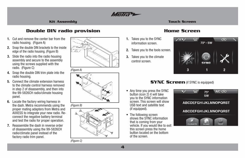
1. Takes you to the SYNC information screen.
2. Takes you to the tools screen.
3. Takes you to the climate control screen.
3 1 2
SYNC Screen (if SYNC is equipped)
• Any time you press the SYNC button (icon 2) it will take you to the SYNC information screen. This screen will show USB text and satellite text (if equipped).
• The following screen shows the SYNC information that is coming from your vehicle. If you would like to exit this screen press the home button located on the bottom of the screen.
1. Cut and remove the center bar from the radio housing. (Figure A)
2. Snap the double DIN brackets to the inside edge of the radio housing. (Figure B)
3. Slide the radio into the radio housing assembly and secure to the assembly using the screws supplied with the radio. (Figure C)
4. Snap the double DIN trim plate into the radio housing.
5. Connect the climate extension harness to the climate control harness removed in step 2 of disassembly, and then into the 99-5826CH radio/climate housing panel.
6. Locate the factory wiring harness in the dash. Metra recommends using the proper mating adapters from Metra and AXXESS to integrate your new radio. Re-connect the negative battery terminal and test the radio for proper operation.
7. Reassemble the dash in reverse order of disassembly using the 99-5826CH radio/climate panel instead of the factory radio trim panel.
Double DIN radio provision
(Figure C)
(Figure A)
(Figure B)
5
Touch Screen
Tools Screens
Tool screen:
• Main menu
(1) Brightness button:
• Pressing this will take you to the brightness menu where you will be able to adjust the nighttime brightness level of the touch screen.
(2) Information button:
• The info button will give you information about what options our kit detects in the vehicle and give you the current version number of the touch screen.
• To Reset: Within the info screen is a reset button. Make sure the vehicle is running and then press and hold the reset button for 10-seconds.
1
2
4
5
3
Continued on next page
6
Touch Screen
Tools Screens
(3) Color button:
• Pressing this button will take you to the skin color menu. Once in this menu you will be able to choose from (12) different skins. Once you have selected your new skin simply touch the home button for changes to take effect.
(4) Trigger button:
• Pressing this button will take you to the Trigger switch screen. These features are optional for the 99-5826CH and are not required for the kit to work. Here you will be able to turn on and off lines 1 through 3 (all outputs are 500mA negitive trigger latched).
Continued on next page
1. Ice Blue
2. Soft Blue
3. Blue
4. Red
5. Green
6. Orange
7. Purple
8. Pink
9. White
10. Water
11. Fire
12. Default
Wiring:
1. Yellow wire – Connect to 12-volt accessory power2. Purple wire (line 1) – Connect to a negative input on a relay3. Brown wire (line 2) – Connect to a negative input on a relay4. Green wire (line 3) – Connect to a negative input on a relay
Note: Included 4-pin harness must be connected to the rear of the touch screen. Use Metra part number E-123 relay for each line needed.
7
Touch Screen
Tools Screens
(5) Compass button (if compass equipped):
• Pressing this button will take you to the Compass calibration menu. Once in this menu please refer to your owner’s manual for further instructions.
• Note: Items that are active are shaded. Also, to toggle between Farenheit to Celsius, please refer the vehicles owners’ manual.
1. Status Bar – Shows current status of the HVAC controls
2. On/Off – Turns A/C on or off
3. Front Defrost – Turns on front defrost
4. Rear Defrost – Turns on rear defrost
5. SYNC button – Takes you to SYNC display screen (if SYNC is equipped)
6. Home button – Takes you to the home screen
7. Tools button – Takes you to the Tools option screen
8. MAX A/C – Turns on Max A/C
9. Recirc button – Toggles between recirculation and fresh air
10. A/C button – Turns on and off A/C compressor
11. Temp control – Takes you to the Temperature adjustment screen
12. Air flow button – Changes the position from which the air flows from
13. Fan button – Takes you to the fan adjustment screen
14. Compass info – Show current compass information (if equipped)
Climate Controls
Climate Controls
1
2
3
4
11
10
9
8
11 12 13
5 6 7 Continued on next page
8
Touch Screen
Climate Controls
FOR SINGlE ZONE CONTROl
(1) Temperature screen:
• Once in the temperature screen you will have an arrow up and down button which will raise or lower the temperature in the vehicle. The line on the colored graph will move each time the arrow is pressed. Once done press the “climate home” button will take you back to the main climate screen. Icon 11 will now show where you set the temperature to.
(2) Airflow button:
• Note: Once set information will show up on the status bar.
• Tapping icon 12 will allow you to change between the 4 airflow modes in the vehicle (face, feet, defrost, face & feet). Once selected icon 12 and the status bar will now show which mode you have selected the air to flow through.
Continued on next page
(3) Fan speed:
• Once in the fan speed screen you will be able to adjust the fan speed by tapping the smaller fan for lowering the fan speed or the larger fan for increasing the fan speed. Once you have selected your desired speed press the “climate home” button to return to the main climate screen. Icon 13 will now show the selected fan speed.
9
Touch Screen
Climate Controls
FOR DuAl ZONE CONTROl
(1) Temperature screen:
• Note: Temperature range is from 60 to 90 degrees.
• Once in the temperature screen you will have an arrow up and down button which will raise or lower the temperature in the vehicle, giving you a numerical temperature reading of the desired temperature. Once done press the “climate home” button will take you back to the main climate screen. Icon 11 will now show the numerical temperature that you set.
(2) Airflow button
• Note: Once set information will show up on the status bar.
• Tapping icon 12 will allow you to change between the 4 airflow modes in the vehicle (face, feet, defrost, face & feet). Once selected icon 12 and the status bar will now show which mode you have selected the air to flow through.
(3) Fan speed:
• Once in the fan speed screen you will be able to adjust the fan speed by tapping the smaller fan for lowering the fan speed or the larger fan for increasing the fan speed. Once you have selected your desired speed press the “climate home” button to return to the main climate screen. Icon 13 will now show the selected fan speed.
(4) Heated and cooled seats (if equipped):
• Note: Once set information will show up on the status bar.
• To access the heated and cooled seats menu you must tap the air flow mode button. Once in that mode you will see the driver and passenger side heated and cooled seat option (if your vehicle has those options equipped). Depending on your vehicle the switches will respond differently. Once done press the “climate home” button will take you back to the main climate screen.
Option 1
• Tapping the driver or passenger heated seat icon will turn heated seated on and off.
Option 2
• Tapping the heated or cooled seat icon will turn the heated or cooled seats on in 3 increments indicated by the number of lines under the seat icon (sequence is low, medium, high, and off).
Continued on next page
10
Touch Screen
Climate Controls
FOR DuAl ZONE TOGGlE (on/off)
• In order to turn on and off dual zone (if equipped) you must enter the temperature adjust mode by pressing icon 11. Once there you can turn dual zone on or off by pressing the Dual zone button in the middle of the screen. Once dual zone is on you will be able to adjust the driver and passenger side air separately. (Please refer to temperature Screen for adjusting the temp) Once done press the “climate home” button will take you back to the main climate screen.
• Download and install the WebXXpress software update from axxessinterfaces.com. Please follow the instructions on the website exactly as stated.
• Connect the USB-CAB update cable (sold separately) into the computer.
• From the Start Menu of the computer, click on “USB Bootloader”, and then click “Update Board”. Wait three seconds and then connect the other end of the USB-CAB cable into the kit. The software will begin to download at this point.
Note: Please note which firmware downloaded to the interface. This will help in troubleshooting, if need be.
KNOWLEDGE IS POWEREnhance your installation and fabrication skills by enrolling in the most recognized and respected mobile electronics school in our industry.Log onto www.installerinstitute.com or call 800-354-6782 for more information and take steps toward a better tomorrow.
PRECAUCIÓN: Metra recomienda desconectar el terminal negativo de la batería antes de comenzar cualquier instalación. Todos los accesorios, interruptores y, especialmente, las luces indicadoras de airbag deben estar enchufados antes de volver a conectar la batería o comenzar el ciclo de ignición.
NOTA: Remítase a las instrucciones incluidas con el radio de postventa.
INSTRUCCIONES DE INSTALACIÓN PARA LA PIEZA 99-5826CH
• Herramienta de remoción del panel • Destornillador Phillips • Destornillador pequeño de paleta
• Provisión de radio ISO DIN con bolsillo• Provisión de radio DIN con bolsillo• Provisión de radio doble DIN• Pintada en gris oscuro para igualar el acabado de fábrica• Controles de clima con pantalla táctil
• A) Panel de moldura del radio/clima • B) Carcasa del radio • C) Soportes ISO • D) Placa de moldura ISO • E) Soportes DDIN • F) Placa de moldura DDIN • G) Bolsillo • H) (4) Ganchos para el panel • I) Clima arnés de la extensión • J) 4-pin arnés de activación
CArACtErÍStICAS dEL KIt
COmPONENtES dEL KIt
Ford Mustang 2010-201499-5826CH
B C D EA
F G H
J
I
99-5826CH
2
Desmontaje del tablero
– Ford Mustang 2010-2014 ...................................................................... 2
Ensamble del kit
– Provisión de radio doble DIN ISO con bolsillo .......................................... 3
– Provisión de radio doble DIN................................................................... 3
– Provisión de radio doble DIN con bolsillo ................................................ 4
Pantalla táctil
– Pantalla de inicio .................................................................................... 4
– Pantalla de herramientas.....................................................................5-7
– Pantalla de controles de clima ...........................................................7-10
- Para el control de una sola zona ........................................................ 8
- Para el control dual de la zona ........................................................... 9
- Para alternar dual de la zona (en/off) ............................................... 10
Indice1. Desenganche y retire el panel de moldura
que rodea la palanca de velocidades, incluyendo los portavasos. (Figura A)
2. Retire los (2) tornillos de 9/32” de la parte inferior del panel del radio y luego desenganche y retire el panel. (Figura B)
Nota: El arnés de 4 pines que se conecta a este panel se conectará a la suministrada 4 pines a 6 pines arnés de la extensión del clima ,y luego en el panel del clima de radio/vivienda 99-5826CH.
3. Retire los (4) tornillos Phillips que sostienen el radio. (Figura C)
4. Retire los ganchos del panel del radio de fábrica o use los ganchos del panel suministrado y colóquelos en la parte posterior de la carcasa del radio.
Continúe con el ensamble del kit
Desmontaje del tablero
(Figura A) (Figura C)
(Figura B)
3
Desmontaje del tablero
1. Retire la funda de metal “DIN“ y anillo de compensación de la radio no original .
2. Los soportes de montaje de la ISO a la radio con los tornillos suministrados con la radio. (Figura A)
3. Coloque la bolsa en la abertura inferior de la carcasa de la radio . (Figura B )
4. Deslice la radio en la abertura superior de la carcasa de radio hasta que el lado clips encajen. (Figura B )
5. Coloque la placa de montaje de ISO en la carcasa de la radio . (Figura C)
6. Conecte el arnés de la extensión climático al arnés climatizador retiró en el paso 2 de desmontaje, y luego en el panel de la radio/clima 99-5826CH .
7. Localice el arnés de cableado de fábrica en el tablero. Metra recomienda utilizar los adaptadores de acoplamiento adecuados de Metra y AXXESS para integrar su nueva radio. Vuelva a conectar el terminal negativo de la batería y probar la radio para su correcto funcionamiento .
8. Vuelva a montar el tablero en orden inverso al desmontaje utilizando la radio / panel del clima 99-5826CH en lugar del panel de ajuste de radio de fábrica .
Provisión de radio doble DIN ISO con bolsillo
(Figura C)
(Figura A)
(Figura B)
Ensamble del kit
1. Retire la funda de metal “DIN“ de la radio no original.
2. Deslizar el manguito en la abertura superior de la carcasa de la radio y seguro doblando las lengüetas de bloqueo de metal hacia abajo. (Figura A)
3. Coloque la bolsa en la abertura inferior de la carcasa de la radio. (Figura B)
4. Deslice la radio de nuevo en la manga hasta que haga clic en.
5. Conecte el arnés de la extensión climático al arnés climatizador retiró en el paso 2 de desmontaje, y luego en el panel de la radio/clima 99-5826CH.
6. Localice el arnés de cableado de fábrica en el tablero. Metra recomienda utilizar los adaptadores de acoplamiento adecuados de Metra y AXXESS para integrar su nueva radio. Vuelva a conectar el terminal negativo de la batería y probar la radio para su correcto funcionamiento.
7. Vuelva a montar el tablero en orden inverso al desmontaje utilizando la radio/panel del clima 99-5826CH en lugar del panel de ajuste de radio de fábrica.
Provisión de radio doble DIN con bolsillo
(Figura B)
(Figura A)
4
Ensamble del kit
Pantalla de inicio
Pantalla táctil
1. Lo lleva a la pantalla de información SYNC.
2. Lo lleva a la pantalla de herramientas.
3. Lo lleva a la pantalla de control de clima.
3 1 2
Pantalla SYNC (si se incluye SYNC en el equipamiento)
• Siempre que presione el botón SYNC ( icono 2), lo llevará a la pantalla de información SYNC. Esta pantalla mostrará el texto USB y el texto del satélite (si se incluye dicho equipamiento).
• La siguiente pantalla muestra la información de SYNC que proviene de su vehículo. Si desea salir de esta pantalla, presione el botón de inicio localizado en la parte inferior de la pantalla.
1. Corte y retire la barra central de la carcasa de la radio. (Figura A)
2. Ajustar los soportes dobles DIN hasta el borde interior de la carcasa de la radio. (Figura B )
3. Deslice la radio en el conjunto de la caja de radio y seguro para el montaje con los tornillos suministrados con la radio. (Figura C)
4. Encaje los dobles DIN recortar placa en la carcasa de la radio.
5. Conecte el arnés de la extensión climático al arnés climatizador retiró en el paso 2 de desmontaje, y luego en el panel de la carcasa de radio 99-5826CH/clima .
6. Localice el arnés de cableado de fábrica en el tablero. Metra recomienda utilizar los adaptadores de acoplamiento adecuados de Metra y AXXESS para integrar su nueva radio . Vuelva a conectar el terminal negativo de la batería y probar la radio para su correcto funcionamiento.
7. Vuelva a montar el tablero en orden inverso al desmontaje utilizando la radio/panel del clima 99-5826CH en lugar del panel de ajuste de radio de fábrica.
Provisión de radio doble DIN
(Figura C)
(Figura A)
(Figura B)
5
Pantalla táctil
Pantalla de herramientas
Pantalla de herramientas:
• Menú principal
(1) Botón de brillo:
• Presionar este botón lo llevará al menú de brillo, donde podrá ajustar el nivel de brillo para la noche de la pantalla táctil.
(2) Botón de información:
• El botón de información le dará información acerca de las opciones que nuestro kit detecta en el vehículo y le dará el número de versión actual de la pantalla táctil.
• Para poner a cero: presione y mantenga presionado el botón de reinicio durante 10 segundos para volver a aprender el vehículo.
1
2
4
5
3
Continúa en la página
6
Pantalla táctil
Pantalla de herramientas
(3) Botón de color:
• Presionar este botón lo llevará al menú de color de carátula. Una vez que se encuentra en este menú, podrá elegir una de las 12 diferentes carátulas. Una vez que haya seleccionado su nueva carátula, simplemente toque el botón de inicio para que los cambios se implementen.
(4) Botón gatillo:
• Presionar este botón lo llevará al menú de interruptor de gatillo. Estas características son opcionales para el 99-5826CH y no se requieren para el kit a trabajar. Aquí podrá activar y desactivar las líneas 1 a 3 (todas las salidas son 500mA gatillo negitive enclavada).
Continúa en la página
1. Azul hielo
2. Azul claro
3. Azul
4. Rojo
5. Verde
6. Anaranjado
7. Morado
8. Rosa
9. Blanco
10. Agua
11. Fuego
12. Predeterminado
Alambre:
1. Cable Amarillo - Conectar a la alimentación de accesorios de 12 voltios.2. Cable Púrpura (línea 1) - Se conecta a una entrada negativa en un relé.3. Cable Marrón (línea 2) - Se conecta a una entrada negativa en un relé.4. Cable Verde (línea 3) - Se conecta a una entrada negativa de un relé.
Nota: Incluye arnés de 4 pines debe estar conectado a la parte trasera de la pantalla táctil. Utilice el número de Metra relé E-123 para cada línea sea necesario.
7
Pantalla táctil
Pantalla de herramientas
(5) Botón de brújula (si está equipado con brújula):
• Presionar este botón lo llevará al menú de calibración de brújula. Una vez que se encuentre en este menú, consulte instrucciones adicionales en su manual de propietario.
• Nota: Los artículos que están activos están sombreados. Además, para cambiar entre Fahrenheit a Celsius, por favor consulte el manual de los vehículos de los propietarios.
1. Barra de estatus - Muestra el estatus actual de los controles HVAC
2. Encendido/apagado - Enciende o apaga el aire acondicionado
3. Descongelamiento frontal - Enciende el descongelamiento frontal
4. Descongelamiento trasero - Enciende el descongelamiento trasero
5. Botón SYNC - Lo lleva a la pantalla de SYNC (si se incluye equipamiento SYNC)
6. Botón de inicio - Lo lleva a la pantalla de inicio
7. Botón de herramientas - Lo lleva a la pantalla de opciones de herramientas
8. MAX A/C – Enciende el Max A/C
9. Botón de recirculación - Alterna entre aire recirculado y aire fresco
10. Botón A/C – Enciende y apaga el compresor A/C
11. Control de temperatura - Lo lleva a la pantalla de ajuste de temperatura
12. Botón de flujo de aire - Cambia la posición desde la cual fluye el aire
13. Control de ventilador - Lo lleva a la pantalla de ajuste de ventilador
14. Información de brújula - Muestra la información actual de la brújula (si incluye dicho equipamiento)
Pantalla de controles de clima
Pantalla de controles de clima
1
2
3
4
11
10
9
8
11 12 13
5 6 7 Continúa en la página
8
Pantalla táctil
Pantalla de controles de clima
PArA El CoNtrol DE uNA SolA zoNA
(1) Pantalla de temperatura:
• Una vez que se encuentre en la pantalla de temperatura, tendrá un botón de flecha hacia arriba y hacia abajo que elevará o disminuirá la temperatura dentro del vehículo. La línea de la gráfica de color se moverá cada vez que la flecha se presione. Una vez que haya hecho esto, presione el botón “inicio de clima”, que lo llevará de regreso a la pantalla principal de clima. Aparecerá ahora el icono 11, donde se configura la temperatura.
(2) Botón de flujo de aire:
• Nota: Una vez que haya configurado la información, ésta parecerá en la barra de estatus.
• Tocar el icono 12 le permitirá cambiar entre los 4 modos de flujo de aire del vehículo (hacia el rostro, hacia los pies, descongelamiento, rostro y pies). Una vez que haya seleccionado el icono 12 y que la barra de estatus muestre cuál modo ha seleccionado, el aire fluirá.
Continúa en la página
(3) Velocidad del ventilador:
• Una vez que se encuentre en la pantalla de velocidad del ventilador, podrá ajustar la velocidad del ventilador tocando el ventilador más pequeño para disminuir la velocidad o el ventilador más grande para aumentar la velocidad. Una vez que haya seleccionado su velocidad deseada, presione el botón “inicio del clima” para volver a la pantalla principal del clima. El icono 13 mostrará la velocidad seleccionada del ventilador.
9
Pantalla táctil
Pantalla de controles de clima
PArA El CoNtrol DuAl DE lA zoNA
(1) Pantalla de temperatura:
• Nota: El rango de temperatura es de 60 a 90 grados.
• Una vez que se encuentre en la pantalla de temperatura, tendrá un botón de flecha hacia arriba y hacia abajo que elevará o disminuirá la temperatura dentro del vehículo, dándole una lectura numérica de la temperatura deseada. Una vez que haya hecho esto, presione el botón “inicio de clima”, que lo llevará de regreso a la pantalla principal de clima. El icono 11 mostrará la temperatura numérica que usted configure.
(2) Botón de flujo de aire:
• Nota: Una vez que haya configurado la información, ésta aparecerá en la barra de estatus.
• Al tocar el icono 12 permitirá al usuario elegir entre los 4 modos de flujo de aire en el vehículo (cara, los pies, descongelación, la cara y los pies). Una vez seleccionado el icono 12 y la barra de estado mostrará ahora el modo que haya seleccionado el aire fluya a través.
(3) Velocidad del ventilador:
• Una vez que se encuentre en la pantalla de velocidad del ventilador, podrá ajustar la velocidad del ventilador tocando el ventilador más pequeño para
disminuir la velocidad o el ventilador más grande para aumentar la velocidad. Una vez que haya seleccionado su velocidad deseada, presione el botón “inicio del clima” para volver a la pantalla principal del clima. El icono 13 mostrará la velocidad seleccionada del ventilador.
(4) Asientos con enfriamiento y calefacción (si se incluyen en el equipamiento):
• Nota: Una vez que haya configurado la información, ésta aparecerá en la barra de estatus.
• Para acceder al menú de asientos con enfriamiento y calefacción, debe tocar el botón de modo de flujo de aire. Una vez que se encuentre en ese modo, verá la opción de asientos con enfriamiento y calefacción para el conductor y pasajero (si su vehículo cuenta con estas opciones de equipamiento). Dependiendo de su vehículo, los interruptores responderán de manera diferente. Una vez que haya hecho esto, presione el botón “inicio de clima”, que lo llevará de regreso a la pantalla principal de clima.
opción 1
• Tocar el icono de la calefacción del asiento del conductor o el pasajero encenderá o apagara la calefacción del asiento.
opción 2
• Tocar el icono de la calefacción o el enfriamiento del asiento encenderá la calefacción o el enfriamiento de los asientos en tres incrementos indicados por el número de líneas que aparecen debajo del icono del asiento. (La secuencia es bajo, medio, alto y apagado)
Continúa en la página
10
Pantalla táctil
Pantalla de controles de clima
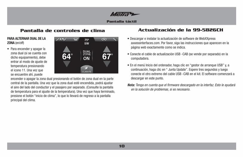
PArA AltErNAr DuAl DE lA zoNA (en/off)
• Para encender y apagar la zona dual (si se cuenta con dicho equipamiento), debe entrar al modo de ajuste de temperatura presionando el icono 11. Una vez que se encuentre ahí, puede encender o apagar la zona dual presionando el botón de zona dual en la parte central de la pantalla. Una vez que la zona dual esté encendida, podrá ajustar el aire del lado del conductor y el pasajero por separado. (Consulte la pantalla de temperatura para el ajuste de la temperatura). Una vez que haya terminado, presione el botón “inicio de clima”, lo que lo llevará de regreso a la pantalla principal del clima.
• Descargar e instalar la actualización de software de WebXXpress axxessinterfaces.com. Por favor, siga las instrucciones que aparecen en la página web exactamente como se indica.
• Conecte el cable de actualización USB -CAB (se vende por separado) en la computadora.
• En el menú Inicio del ordenador, haga clic en “gestor de arranque USB” y, a continuación, haga clic en “ Junta Update”. Espere tres segundos y luego conecte el otro extremo del cable USB -CAB en el kit. El software comenzará a descargar en este punto.
Nota: Tenga en cuenta que el firmware descargado en la interfaz. Esto le ayudará en la solución de problemas, si es necesario.
KNOWLEDGE IS POWEREnhance your installation and fabrication skills by enrolling in the most recognized and respected mobile electronics school in our industry.Log onto www.installerinstitute.com or call 800-354-6782 for more information and take steps toward a better tomorrow.
Metra recomienda técnicos con certificación del Programa de Certificación en Electrónica Móvil (Mobile Electronics Certification Program, MECP).
EL CONOCIMIENTO ES PODERMejore sus habilidades de instalación y fabricación inscribiéndose en la escuela de dispositivos electrónicos móviles más reconocida y respetada de nuestra industria. Regístrese en www.installerinstitute.com o llame al 800-354-6782 para obtener más información y avance hacia un futuro mejor.
INSTRUCCIONES DE INSTALACIÓN PARA LA PIEZA 99-5826CH