Instabilities and self-pulsation in a ring cavity with aphotorefractive wave mixer
Shimon Weiss and Baruch Fischer
Department of Electrical Engineering, Technion-Israel Institute of Technology, Technion City, Haifa 32000, Israel
Received April 27, 1989; accepted August 10, 1989
We find instabilities and self-pulsation in an optical ring cavity with a photorefractive two-wave mixer. The mean-field limit is used to obtain a single criterion for instabilities that originate from a Hopf bifurcation.
Optical bistability and instabilities1 in photorefractivewave mixing have been reported recently.2-4 Some ofthese studies were based on competition between sev-eral coupled oscillators (or sets of gratings).3 Bistabil-ity and self-pulsation in a photorefractive ring cavity(with two crystals in the cavity) were also demonstrat-ed. 4
We have shown5 that photorefractive two-beamcoupling in a ring cavity exhibits absorptivelike anddispersivelike bistabilities. With the application of adc electric field and nondegenerate mixing, the behav-ior of the system resembles the Stark effect with gainsplitting and broadening.6'7 In this Letter we showthat this configuration also displays optical instabil-ities and self-pulsation in the single-mode, mean-fieldlimit.7'8 We also obtain a single criterion for suchinstabilities.
The dynamics of two-beam coupling in a photore-fractive material is described by the time-dependentMaxwell equations for the propagating waves and amaterial equation that governs the coupling processthrough the dynamical formation of the space-chargefield and the gratings. This process is described bythe band-transport model of Kukhtarev et al.9 In thequasi-cw (steady) approximation'0 it is assumed thatthe density of the mean carrier number is independentof time. In this case the grating buildup (or erasure) isgoverned by a single (complex) time constant.
Figure 1 shows the two-beam-coupling configura-tion considered here. Our treatment allows for a mov-ing grating and the application of an external dc elec-tric field upon the crystal." With the standard slowlyvarying amplitude and plane-wave approximations,and for negligible absorption, the equations for thetime-dependent beam-coupling process are
+ c'_ dd =1 =- GA4,
+ c' )A4* = + -GA*,dt ({ tEoA14no
= VO[~2 l f(E0 )AlA 4 * - G(10 + iAO)],
(la)
(lb)
(lc)
where Aj(z, t) are the beams' complex amplitudes, Ij =IAjI2, Io = I, + I4, G(z, t) is the grating's complex
amplitude, c' = (c cos 0)/no, 0 is the angle of the beamswith respect to the normal to the crystal face (see Fig.1), ai gives the direction of the energy transfer accord-ing to its sign (a = ±1) and is dependent on the orien-tations of the crystal and the two beams, Eo is theexternally applied field, ro = to/Io is the time constantfor Eo = 0, and to vo-' is the time constant for thegrating formation, normalized to intensity units, andis a constant of the material for a given geometry. Thereciprocal dependence of the time constant on thetotal light intensity is valid only for intensities wellbelow saturation. A more exact relation is given by ro= to X I-X, where12 0.6 < x < 0.7. A = (W1 - W4) To is thedynamical detuning of the grating. The static detun-ing is defined by Ao -- (W1 - cv4)to (=const.). We notethat c, - W4 << W1, (04, and therefore the phase mis-match is negligible. f(Eo) is a complex function thatdescribes the changes in the grating's complex ampli-tude due to E0 and is given by5 f(Eo) = [(Ed + Ep)/Ed]J(Eo + iEd)/[Eo + i(Ed + Ep)I - F + iF'. n1 is themaximum change of the index of refraction with Eo =A = 0 and is given by n1 = -reffno3 l(EdEp)/[2(Ed +Ep)]} such that its multiplication by iAlA4*/Io givesthe complex grating's amplitude, G(x, t). reff is theeffective electro-optic coefficient, and no is the back-ground index of refraction. Ed and Ep are materialparameters5 for a given geometry.
The boundary condition for the ring configurationof Fig. 1 is
I1 (O)
1, in og04 4ut
BS I4 (0) 9,,, I4 (1) BS
M
Fig. 1. Photorefractive unidirectional ring cavity with aninjected signal. C, crystal; V, voltage source; BS's, beamsplitters; M's, mirrors.
where At (- - 1)/c', L is the total effective cavitylength, and I is the interaction length of the two beamsin the crystal. T and R are the transmissivity and thereflectivity, respectively, of the input and outputbeam splitters (T = 1 - R). The cavity detuning 30 isdefined by 3o _= (4 -cv)/(c/L), where xc = q(27rc/l-) isthe cavity mode nearest to the frequency of the inci-dent field, (4 (q is an integer).
The configuration shown in Fig. 1, without the in-jected signal and with ai = +1, has been previouslystudied in detail and is known as the photorefractiveunidirectional ring oscillator.'3 With the inclusion ofthe injected signal, the case of ai = +1 is similar to thatof a laser with an injected signal. The case of a = -1 issimilar to that of the optical bistability configuration.The steady-state solution of Eqs. (1) with the bound-ary conditions of Eq. (2) was given in Ref. 5. It wasshown that this system exhibits absorptivelike anddispersivelike optical bistabilities. This solution,however, did not include power-broadening effectsthat originate from the photorefractive Stark effect.7
In the mean-field limit8 the electromagnetic fieldsand the grating's amplitude inside the medium aretaken to be almost uniform in space. This approxima-tion is valid when the nonlinear interaction of thebeams, the transmissivity of the beam splitters, andthe cavity detuning are small8:
'yol O0 , T 0, 0 -0, (3)
where yo is the steady-state resonant (Eo = A0 = 0)coupling coefficient, yo (=vn,/2noc').
We follow the derivations of Ref. 8 using the mean-field limit. The steady-state quantities and the dy-namical perturbations are treated separately and thenrecombined to give a new set of quantities: Al(z', t')A, 6 +_a,(z', t'), A4*(z', t') A455* + a4*(z0, t'), and G(z',t') G5. + 6G(z', t') with a new set of variables, z' = zand t' = t + At(z/l). These changes convert theboundary condition of Eq. (2) into a periodic one.The new set of equations is then given by
(atl ' L aid)A
= 'r -1 [Al..(l) -Al.(0)] -a ic' IA4 I
( Ct' 1 -Ls ' A4}
(4a)
govern the dynamical behavior of the system. Sincethe time response of the photorefractive effect is rela-tively slow owing to carrier-transport mechanisms,and since T -0, we have p << Tcav, to. Then Eq. (4a)'can be adiabatically eliminated and A, can be regard-ed as a constant in space and time. This result is notsurprising; photons that originate from beam 1 tra-verse the crystal only once and leave the system. Pho-tons of beam 4, however, have a long cavity lifetime(rcav is reciprocally dependent on T). With the as-sumption of relations (3) of weak interaction, onlythese photons experience the nonlinear coupling ef-fects. Thus we can assume that A(0, t) _ A(l, t)constant. Because the photorefractive linewidth PO isnarrow with respect to the free spectral range of thecavity, we consider the single-mode equations onlyand therefore omit the spatial derivatives8 from Eqs.(4). This means that the photorefractive gain mecha-nism cannot supply enough gain to other cavity modesbesides the one with w,.
Then we obtain our basic equations of the single-mode, mean-field-limit model for the photorefractivering cavity:
x = -k[(1 + i0)x - y + 2C9g],
g = vo[(F + iF')x - (1 + Ix12 + iAo)g],
(5a)
(5b)
where x A4 */Al = A4outJ[FTAl(0)] is the normalizedoutput amplitude, y A4in/[JTA(0)] is the normalizedinput amplitude, C - yol/2T is the bistability parame-ter, and g - 2iG/n, is the normalized grating's ampli-tude. For normalization purposes we take A,(0) = 1and then lo = 1 + 1x12. The normalized input andoutput intensities are defined by Y y 2 and X -x12,respectively, and g = JgJ2.
The steady-state solution of Eqs. (5) is given by
X 40------ --
20
0 30 - . 0 0: -. 0 30 60 Y
8o- -f-8. (b
2.5
I X, O
4
0 - . . _ ._ - .- -_._
= r -1 [_(1 + +T no c'T
-, = to 2 f (Eo)AlA - G(10 + iAo) X (4c)
with T ep = /c',av = th = d/CfT, 0 = 0 /T, and 10 = c t+ 14. We note that three different time constants
1.5 MY
-2.5
2.5
X, 0
-2.5
~-2.5 0.2.5-
t251
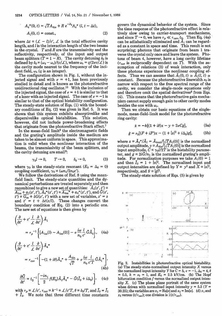
Fig. 2. Instabilities in photorefractive optical bistability.(a) The steady-state-normalized output intensity X versusthe normalized input intensity Yfor C = 5, ai = -1, AO = 4, 0= 0.5, k = vo = 1, and Eo = 2.5 kV/cm. (b) The Hopfbifurcation condition f versus the normalized output inten-sity X. (c) The phase plane portrait of the same systemwhen driven with normalized input intensity y = 5.5 (Y =30.25); the variables are xl = Relxl and X2 = Imtxl. (d) xl andX2 versus (t/rcav); one division is 1 (t/rcav).
With a zero applied field (F = 1, F' = 0) this result isidentical to Eq. (21) of Ref. 5, when power-broadeningeffects are added [the substitution of A = AO/(I + X)].
We next study the local stability of the systemthrough linear stability analysis. We assume smallperturbations of the forms ax = x - x8 and ag = g - go,where x, and g, are the steady-state solutions of Eqs.(5). Substituting these perturbations into Eqs. (5)and taking only the linear terms, we have
A transition of the system from a stable state to insta-bility occurs14 when a negative real root passes theorigin (from left to right) or when two complex conju-gate roots (with a negative real part) cross the imagi-nary axis of the complex plane. The first case (saddle-node bifurcation) occurs when a4 changes its sign andbecomes negative. This corresponds to the turningpoints of the negative-slope branch of the input/out-put curve of the photorefractive ring cavity. It can beshown that dY/dX = [a4/(k2vo2)1{1/[(l + XJ)2 + A0
2]},which shows that the negative branch, as is usual inoptical bistability, is always unstable. The secondcase corresponds to Hopf bifurcation and is of moreinterest to us because it can lead to positive-slopeinstabilities and self-pulsation. A single critical crite-rion for the Hopf bifurcation can be obtained as donein Ref. 14. By substituting X = ip, A > 0 into Eq. (8),the polynomial breaks into real and imaginary parts:A4- a2Au2 + a4 = 0 and aly 2 - a3 = 0. The frequency ofoscillations on the instability boundaries is found to beIL = V/a7sa, (with the requirement that a3/a, > 0).Then the condition for Hopf bifurcation is derived:
(9)
In fact, this is the next to last principal subdetermin-ant of the Routh-Hurwitz criterion,15 which is the firstto change its sign in the case of Hopf bifurcation.This also means that f < 0 is a sufficient condition forinstability.
In Fig. 2 we give a numerical example that demon-strates instabilities in photorefractive optical bistabil-ity. In Fig. 2(a) the steady-state solution [Eq. (6)] isdrawn, where the Hopf bifurcation condition [Eq. (9)]is applied to obtain the unstable regions. The param-eters used are C = +5, o- = -1, A0 = 4, 0 = 0.5, k = Po =1, and Eo = 2.5 kV/cm. The unstable regions are
labeled by dashed curves. In Fig. 2(b) we give f, theinstability criterion, as a function of X for this exam-ple. As can be seen, instabilities appear in the lowerbranch of the bistability curve, starting from the zeroinput field. In Figs. 2(c) and 2(d) we drive the samesystem in the unstable region, near its boundary, witha normalized input amplitude y = 5.5 (Y = 30.25).The driving intensity is marked by an arrow in Fig.2(a). Figure 2(c) is a phase portrait of Eqs. (5) for thetwo variables xl = Refx} and x2 = Imfx}. These twovariables are also drawn as a function of time in Fig.2(d). All the numerical calculations were done with afourth-order Runge-Kutta algorithm, with a step sizeof 0.05 (smaller step sizes gave the same attractor),and all the transients were allowed to decay before any
data were taken. A more detailed explanation forthese instabilities, through the gain-feedback ap-proach,' 6 is given in Ref. 7.
References
1. R. W. Boyd, M. G. Raymer, and L. M. Narducci, eds.,Optical Instabilities (Cambridge U. Press, Cambridge,UK, 1986).
2. B. Fischer, M. Cronin-Golomb, J. 0. White, and A.Yariv, Opt. Lett. 6, 519 (1981).
3. See, e.g., S. Kwong, M. Cronin-Golomb, and A. Yariv,Appl. Phys. Lett. 45, 1016 (1984); G. C. Valley and G. J.Dunning, Opt. Lett. 9, 513 (1984).
4. D. M. Lininger, P. J. Martin, and D. Z. Anderson, Opt.Lett. 14, 697 (1989).
5. S. Weiss and B. Fischer, Opt. Commun. 70, 515 (1989).6. Y. R. Shen, The Principles of Nonlinear Optics (Wiley,
New York, 1984).7. S. Weiss and B. Fischer, submitted to Phys. Rev. A.8. L. A. Lugiato, in Progress in Optics, E. Wolf, ed. (North-
Holland, Amsterdam, 1984), Vol. 21, p. 69.9. N. V. Kukhtarev, V. B. Markov, S. G. Odulov, M. S.
Soskin, and V. L. Vinetski, Ferroelectrics 22,949 (1979).10. G. C. Valley and J. F. Lam, in Photorefractive Materials
and Their Applications I, P. Gunter and J. P. Huignard,eds. (Springer-Verlag, Berlin, 1988), p. 75.
11. The combination of a moving grating and an appliedfield was first studied by J. P. Huignard and A. Marrak-chi, Opt. Commun. 38, 249 (1981). A comprehensivestudy is given by Ph. Refregier, L. Solymar, H. Rajben-bach, and J. P. Huignard, J. Appl. Phys. 58,45 (1985).
12. S. Ducharme and J. Feinberg, J. Appl. Phys. 56, 839(1984).
13. J. 0. White, M. Cronin-Golomb, B. Fischer, and A.Yariv, Appl. Phys. Lett. 40, 450 (1982).
14. H. Gang and Y. Guo-jian, Phys. Rev. A 38, 1979 (1988).15. See, e.g., H. Haken, Synergetics-An Introduction
(Springer-Verlag, Berlin, 1983), p. 124.16. I. Bar-Joseph and Y. Silberberg, Opt. Commun. 48, 53
(1983); J. Opt. Soc. Am. B 1,662 (1984); Phys. Rev. A 36,1731 (1987).