P/N 962830A-1(A), 962830A-2(A), 962830A-3(A) Page ii of vi
PAGE CONTROL CHART
SECTION DESCRIPTION PAGE NO.
3.0 CERTIFICATION 3-1 Supplemental Type Certificate 3-2 4.0 PLACING AN ORDER 4-1 5.0 INSTALLATION PROCEDURE 5-1
5.1 General 5-1 5.2 F/ADC Location Selection 5-1 5.3 Mounting the F/ADC 5-1 5.4 Mounting the OAT Probe 5-2 5.5 Connection to the Fuel Flow Sensor 5-3 5.6 Connection to the Heading Source 5-4 5.7 Connection to the Pitot and Static Lines 5-5 5.8 Connection to the Navigation Management System 5-6 5.9 Connection to the Altimeter Baro Pot 5-6 5.10 Post Installation Checkout 5-6
6.0 OPERATING INSTRUCTIONS 6-1 7.0 INITIALIZATION 7-1 8.0 MAJOR COMPONENTS OF THE SYSTEM 8-1
P/N 962830A-1(A), 962830A-2(A), 962830A-3(A) Page vi of vi
REVISION LOG
REV DATE APP’D CHANGE
– 12-08-98 KCL Baseline release
A 06-17-99 KCL Update pages 2-1, 2-7 – 2-10, 5-5, 9-9, header and grammar, changed Dwg revisions as indicated.
B 09-18-00 EDJ
Moved page 9-11 to 9-16. Added pages 9-11 to 9-15. Corrected page 9-4 and 9-7 for Bendix letter description. Updated OAT probe kit P/N’s. Changed page iv for Dwg # 4028-A45 to include Garmin 430/530. Page vi changed to include Dwg # 4028-B98. Changed page 2-1 to adjust OAT tolerance. Changed page 2-3 to add labels 234 and 235. Change 2-4 and 2-5 to include Mk VI and VIII EGPWS models. Changed page 5-4 to add Sandel heading source. Page 5-1 changed by inclusion of TSO compliance paragraph. Inserted page 3-2 STC.
C 11-01-00 KCL Added sections 2.8 and 2.9. Updated sections 1.4, 2.0, 5.1, 5.7 and 9.2. Moved section 9.0 to page iii. Moved page 9-16 to 9-21. Updated Dwg # 4028-A47.
D
06-27-02
EDJ Updated section 1.3 system figure. Added P/N 681201 OAT probe installation and parts list to page iv drawing list. Updated Page 2-4 ARINC Table. Corrected page 10-3 Table 2. Added pages 9-21 to 9-26. Page 9-21 became 9-27.
E 04-12-05 ZK Removed P/N 681201A-1 OAT Probe Assembly Kit, Loop-back procedure SW Version 93.00.79. Updated pages 2-1, 2-12, 5-2, section 9 and section 11. Changed company name.
F 09-19-05 CB Updated install kit IK9630A-1, Dwg # 4028-395. Updated Section 1.3 system figure and sections 5.1and 5.2. Fixed typo in section 2.6.2.
G 12-08-05 CB Updated Company logo and install kit IK9630A-1
H 04/24/08 EDJ Updated all sections with P/N 962830A-1(A), -2(A), & -3(A), updated Section
2.2, 2.5.2, 2.5.3, 2.7, 3.0, 5.1, and 9.0. Added Antonov and Yak-40 SSEC information in Section 2.6.4.
J 07/18/11 ZK Updated 4028-B98 Rev D and 681201-1 Rev H parts list. Fixed tabs on page 1-1 so that it doesn’t get corrupted when creating a pdf. Replaced missing Table 4 – MACH Tolerance and updated all of section 2 to compensate for the added page. Corrected the Table numbers and descriptions in section 9. Updated the table of contents to reflect all the changes.
The information in this manual is subject to change without notification. To ensure complete and current updates, note the Revision Log above and call Technical Assistance for updated information.
This manual is designed to facilitate the installation of the Shadin Fuel/Air Data Computer (ADC 2000).
1.2 Product Information The Shadin ADC 2000 system is designed to provide a combined source of fuel and Air Data. Listed below are the navigational systems that the ADC 2000 has been designed to be compatible with. Receives Serial Data from: Magellan Skynav 5000 ARNAV Trimble Bendix King STAR 5000 2000/2000A KLN90 FMS 7000 2100/3000 KLN90A R5000 3100/2101 KLN90B KLN89/89B KLN900 Garmin BFGoodrich IIMorrow 150, 155, 155XL, 165 Pronav LNS 6000 611, 612, 618 230, 230XL NMS 2001 300, 300XL 800, 820, 360 430, 530 GX50, 55, 60 Transmits Serial Data to: ARNAV Magellan Note: To find out which particular receiver Bendix/King Trimble models have AIR DATA receive capability, Garmin contact the manufacturers.
Transmits ARINC Data to: ASINC Bendix King Honeywell Universal Airshow EFIS 40/50 SPZ-5000 UNS-1M Data Nav III Global Trimble IIMorrow GNSX TNL8100 2101 GNS-Xls
FUEL/AIR DATA COMPUTER Rev: J P/N 962830A-1(A), 962830A-2(A), 962830A-3(A) Page: 1-2 1.3 System Configuration
The Fuel/Air Data system is a remote mounted computer, which is connected to the GPS receiver via serial data. It is also connected to the pitot and static line, OAT probe, fuel flow sensors, altimeter barometric pressure potentiometers and the aircraft heading source.
Shown below is an optional system configuration utilizing a Shadin Fuel Flow Indicator. Note that the only navigational receivers supported in this configuration are the Bendix/King KLN series and the Garmin 430/530. Consult Drawing Number 4028-A60 contained in this manual for installation information on the Bendix/King KLN series. Consult Drawing Number 4028-B98 for installation information on the Garmin 430/530.
Bendix/King
KLN90, A, BKLN89KLN900
Shadin
DigiFloMiniFloMicroFlo
Shadin
F/ADC200F/ADC2000
RS-232
RS-232RS-232
Garmin
430,530 L.Fuel Flow Transmitter
R. Fuel Flow Transmitter
or
1.5 F/ADC2000, Argus Moving Map Configuration
Shown below is the system configuration that supports output to an Eventide Argus moving map using the Shadin serial to serial data converter P/N 937000-03. The fuel and AIR DATA are displayed on the Eventide-Argus moving map. Consult Drawing numbers 4070-005 and 4028-A61 contained in this manual.
FUEL/AIR DATA COMPUTER Rev: J P/N 962830A-1(A), 962830A-2(A), 962830A-3(A) Page: 2-1 2.0 FUEL AND AIR DATA SYSTEM SPECIFICATIONS
2.1 Input Data Range
Pitot 20 to 350 kt. Static -1000 to 55,000 ft. OAT -60°C to +60°C Heading 0 - 360° Fuel Flow 1 to 450 GPH Range Selected K-Factor 500 to 130000 PPG Continuous
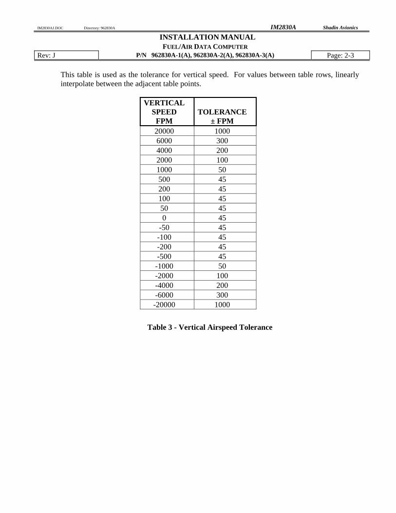
2.2 Output Data Range PARAMETER Accuracy* RANGE IAS Table 1 20 to 350 kts. P.ALT Table 2 –1000 to 50000 ft. OAT ±1.5°C per TSO –60°C to +60°C TRUE HEADING ±2° 0 - 360 degrees MAGNETIC HEADING ±1° 0 - 360 degrees IVS Table 3 ± 10,000 ft./min. TAS Table 1 20 - 600 kts. MACH Table 4 .2 - .95 WIND SPEED ±5 kts. 5 - 360 kts. WIND DIRECTION ±10° 0 - 360 degrees FUEL FLOW ±2% 1-450 GPH * Listed accuracies are after warm-up is complete per the ambient temperatures listed in Section 2.6.1
This table is used as the tolerance for pressure altitude. Note that for an altitude between points in the tables, the tolerance is linearly interpolated between the adjacent table points.
2.4 Power Requirements System Power required: 28 VDC @ 1300 mA 14 VDC @ 900 mA
2.5 Output Data
1. Electric Format: RS-422 or RS-232 2. ARINC 429 low/high speed GAMA (Has to be configured at the factory)
See paragraph 2.5.3 for ARINC 429 output data capabilities.
2.5.1 Serial Output Data Parameters
Fuel Group AIR DATA Group L. ENG. Fuel Flow Pressure Altitude Rate of Turn R. ENG. Fuel Flow Density Altitude MACH Number Fuel Used Total Barometric Corrected Altitude Wind Direction and Speed Total Fuel Used Indicated Air Speed Baro Correction (mb #1) Fuel Used L. ENG. True Air Speed Baro Correction (hg”) Fuel Used R. ENG. Vertical Speed Fuel Remaining True Air Temperature NM/Fuel Unit (ground) Outside Air Temperature Fuel to Destination Drift Angle Fuel at Destination Magnetic Heading
Note: Not all parameters will be available to all navigational receivers. Contact the manufacturer for display capabilities.
FUEL/AIR DATA COMPUTER Rev: J P/N 962830A-1(A), 962830A-2(A), 962830A-3(A) Page: 2-6 2.5.2 ARINC 429 Labels Associated with Switch Settings
In Table 5 – ARINC Label Configuration below, the heading row containing the numbers 1-A indicates the setting of the ARINC rotary switch on the back of the unit. The number in the cell at the intersection of an ARINC switch setting and an ARINC label number is the repeat time in msec for that label. Zero indicates that the label is not generated with that switch setting. Tolerance on the rate is ± 10% averaged over one second.
FUEL/AIR DATA COMPUTER Rev: J P/N 962830A-1(A), 962830A-2(A), 962830A-3(A) Page: 2-7 2.5.3 ARINC 429 Labels Associated with Switch Settings
0 - Honeywell SPZ-5000 for Cessna 6 - Trimble 8100 (No label 275) 1 - Bendix KLN90B or Global GNSXC(LS) 7 - TNL-8100 2 - HUD-Heads Up Display for Flt Visions 8 - Collins FMS 800 (100 ms rate) 3 - UNS1 9 - Mk VII GPWS (50 ms rate) 4 - EFIS40/50 A - Mk VI and VIII EGPWS (50 ms rate) 5 - ASINC Airshow Cabin Display Note that 3 and 6 are the same except for label 275. The following is a list of the different switch settings that the ARINC switch may be set to. The ARINC switch position is shown in section 9.2. 0 - Long Range Nav function of Honeywell SPZ-5000 Flight Guidance/EFIS System
installed on the Cessna Citation Jet Aircraft. 1 - Bendix to Global/Cabin Info System installed on the Cessna Citation Jet Aircraft. 2 - Reserved 3 - 8100, UNS1 4 - Bendix/King EFIS 40/50 5 - ASINC Airshow 6 - 8100, UNS1, except no label 275. Use when there is no serial navigation data
being received by the ADC2000. 7 - TNL-8100, with total fuel flow label 244 8 - Collins FMS 800 (100 ms rate) 9 - Allied Signal, Mk VII GPWS (50 ms rate) A* - Allied Signal, Mk VI and VIII EGWS (50 ms rate) * for ARINC software version 71.73.01 and up
The Fuel/AIR DATA System requires a warm-up time that varies with ambient temperature: 70°C ambient 5 minutes warm-up required 15°C ambient 10 minutes warm-up required -20°C ambient 15 minutes warm-up required -40°C ambient 20 minutes warm-up required
If the ADC has been configured for a fuel flow delay, fuel flow and thus fuel used information shall be unavailable at startup for the duration of the selected delay.
2.6.2 Supplemental equipment All Shadin F/ADC(s) and ADC(s) are not designed to replace factory installed AIR DATA fuel flow systems or other gauges. They are not intended to be used as a primary system to drive altimeters or airspeed indicators. The F/ADC fuel section is not a fuel quantity system and therefore reports only what was manually entered by the operator.
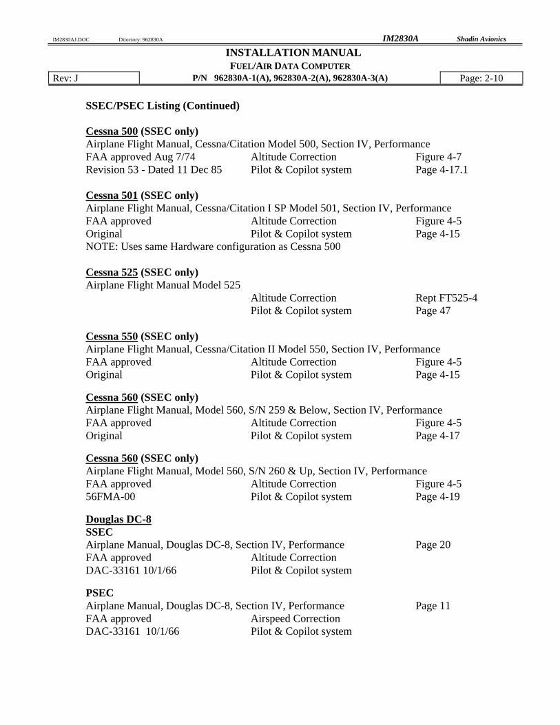
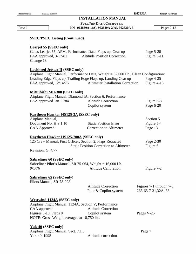
2.6.3 Static Source Error Correction (SSEC),
Pitot Source Error Correction (PSEC) For certain models of aircraft, the Fuel/AIR DATA System will make corrections to pressure altitude by compensating for static source error. For some of these models, the Fuel/AIR DATA System will make corrections to indicated airspeed by compensating for pitot source error.
The System does not provide true and absolute readings for all circumstances. It makes no altitude corrections when the uncorrected IAS is below 100 knots, and it makes no airspeed corrections when the uncorrected IAS is below 150 knots. It does not account for other factors, such as the current useful weight, that contribute to static source error and pitot source error. Rather, the Fuel/AIR DATA System performs calculations based solely on indicated airspeed and pressure altitude. The SSEC / PSEC corrections were derived from specific aircraft data referred to in section 2.6.4. To configure the Shadin F/ADC for a specific aircraft model refer to section 9.
SSEC/PSEC Listing (Continued) Cessna 500 (SSEC only) Airplane Flight Manual, Cessna/Citation Model 500, Section IV, Performance FAA approved Aug 7/74 Altitude Correction Figure 4-7 Revision 53 - Dated 11 Dec 85 Pilot & Copilot system Page 4-17.1 Cessna 501 (SSEC only) Airplane Flight Manual, Cessna/Citation I SP Model 501, Section IV, Performance FAA approved Altitude Correction Figure 4-5 Original Pilot & Copilot system Page 4-15 NOTE: Uses same Hardware configuration as Cessna 500
Cessna 525 (SSEC only) Airplane Flight Manual Model 525 Altitude Correction Rept FT525-4 Pilot & Copilot system Page 47
Cessna 550 (SSEC only) Airplane Flight Manual, Cessna/Citation II Model 550, Section IV, Performance FAA approved Altitude Correction Figure 4-5 Original Pilot & Copilot system Page 4-15
Cessna 560 (SSEC only) Airplane Flight Manual, Model 560, S/N 259 & Below, Section IV, Performance FAA approved Altitude Correction Figure 4-5 Original Pilot & Copilot system Page 4-17
Cessna 560 (SSEC only) Airplane Flight Manual, Model 560, S/N 260 & Up, Section IV, Performance FAA approved Altitude Correction Figure 4-5 56FMA-00 Pilot & Copilot system Page 4-19
Douglas DC-8 SSEC Airplane Manual, Douglas DC-8, Section IV, Performance Page 20 FAA approved Altitude Correction DAC-33161 10/1/66 Pilot & Copilot system
PSEC Airplane Manual, Douglas DC-8, Section IV, Performance Page 11 FAA approved Airspeed Correction DAC-33161 10/1/66 Pilot & Copilot system
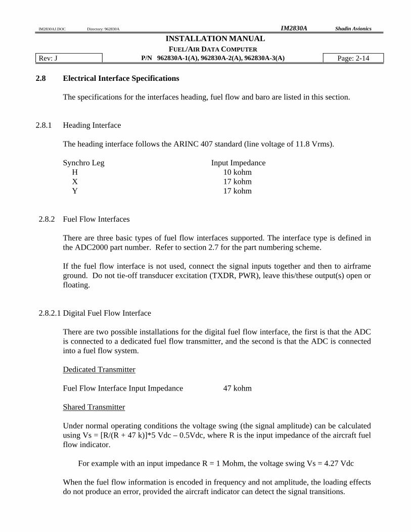
The specifications for the interfaces heading, fuel flow and baro are listed in this section.
2.8.1 Heading Interface
The heading interface follows the ARINC 407 standard (line voltage of 11.8 Vrms). Synchro Leg Input Impedance
H 10 kohm X 17 kohm Y 17 kohm
2.8.2 Fuel Flow Interfaces
There are three basic types of fuel flow interfaces supported. The interface type is defined in the ADC2000 part number. Refer to section 2.7 for the part numbering scheme. If the fuel flow interface is not used, connect the signal inputs together and then to airframe ground. Do not tie-off transducer excitation (TXDR, PWR), leave this/these output(s) open or floating.
2.8.2.1 Digital Fuel Flow Interface There are two possible installations for the digital fuel flow interface, the first is that the ADC is connected to a dedicated fuel flow transmitter, and the second is that the ADC is connected into a fuel flow system. Dedicated Transmitter Fuel Flow Interface Input Impedance 47 kohm Shared Transmitter Under normal operating conditions the voltage swing (the signal amplitude) can be calculated using Vs = [R/(R + 47 k)]*5 Vdc – 0.5Vdc, where R is the input impedance of the aircraft fuel flow indicator.
For example with an input impedance R = 1 Mohm, the voltage swing Vs = 4.27 Vdc When the fuel flow information is encoded in frequency and not amplitude, the loading effects do not produce an error, provided the aircraft indicator can detect the signal transitions.
The interface source signal amplitude varies with frequency. Listed in the table below are the input impedance vs. peak to peak input voltages of the ADC2000 under normal operating conditions.
Input Impedance Input Voltage 2 Mohm Input voltage less than or equal to 1.0 Vpp 24.5 kohm Input voltage greater than 1.0 Vpp
Maximum Input Voltage 10 Vpp
2.8.2.3 DC Voltage Fuel Flow Interface The DC voltage fuel flow interface has a differential input. The specifications under normal operating conditions are listed below. Positive input greater than 100 Mohm Negative input greater than 100 Mohm Maximum Input Voltage 10.2 Vdc
2.8.3 Baro Interface The baro interface requires a three-wire connection to the potentiometer housed in the aircraft altimeteri. The three connections are the high side, low side and wiper. The specifications under normal operating conditions are listed below. Input Impedance high side greater than 100 Mohm Input Impedance low side greater than 100 Mohm Input Impedance wiper greater than 100 Mohm Maximum Input Voltage ± 12 Vdc
i The altimeters supported are listed in section 9.2 and are dependent upon the ADC2000 software version level.
Temp. ALT F2 Temp. Variation B Humidity A Shock & Vibration P, K, S, M, N, O Magnetic Effect B Power Input B Voltage Spike B AF Conducted Susceptibility B Induced Signal Susceptibility B RF Susceptibility A RF Emission B Software Certification
P/N 962830A-1, 962830A-2, and 962830A-3 conforms to level II as defined by RTCA/DO-178A.
P/N 962830A-1A, 962830A-2A, and 962830A-3A conforms to level D as defined by RTCA/DO-178B.
FUEL/AIR DATA COMPUTER Rev: J P/N 962830A-1(A), 962830A-2(A), 962830A-3(A) Page: 4-1 4.0 PLACING AN ORDER
Please know the aircraft year and model number, its serial number, and the engine make and model number when you call to place orders. Information on the fuel flow system previously installed in the aircraft and any communication interface (RS-232, RS-422 and ARINC 429) information may also prove useful. We may request a wiring diagram of the aircraft's fuel flow system and transducer and/or K-factors. When interfacing an altimeter to the Shadin barometric pressure potentiometer option, consult the list of supported altimeters contained in this manual or contact Shadin Technical Support.
The conditions and tests required for TSO approval of this article are minimum performance standards. It is the responsibility of those installing this article either on or within a specific type or class of aircraft to determine that the aircraft installation conditions are within the TSO standards. TSO articles must have separate approval for installation in an aircraft. The article may be installed only if performed under 14 CFR part 43 or the applicable airworthiness requirements. All work must conform to AC 43.13-1B; latest release.
5.2 F/ADC Location Selection The Fuel AIR DATA Computer should be mounted in a dry, temperature stable location with enough distance from motors, pulse generating equipment, relays and cables carrying high DC or AC current to avoid interference with low level signals of the OAT and fuel flow. The equipment may be installed in non-pressurized and non-controlled temperature location. In considering the location, keep in mind that the F/ADC requires signals from the fuel flow, the OAT probe, heading system and the pitot and static lines. Placement in the front section of the aircraft is favorable, in order to avoid running all of these signals to the tail of the aircraft.
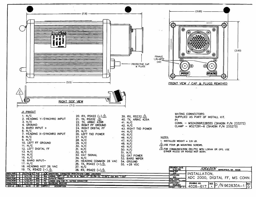
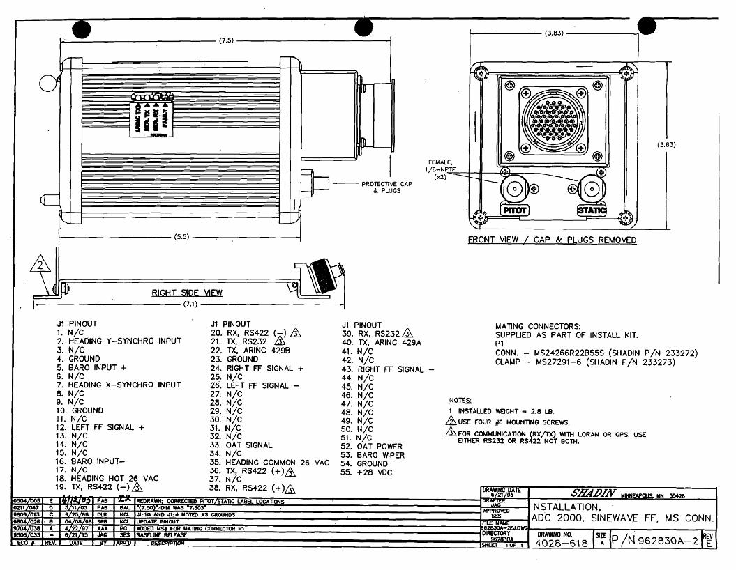
5.3 Mounting the F/ADC Consult the Drawings 4028-617 or 4028-618 or 4028-619 and Drawing 4028-395, Before mounting the ADC2000. Use the recommended hardware. Any orientation is acceptable. Make sure that the computer is not the lowest point in the pitot and static system, to reduce the chances of collecting moisture or water in it. Form a water trap, if necessary.
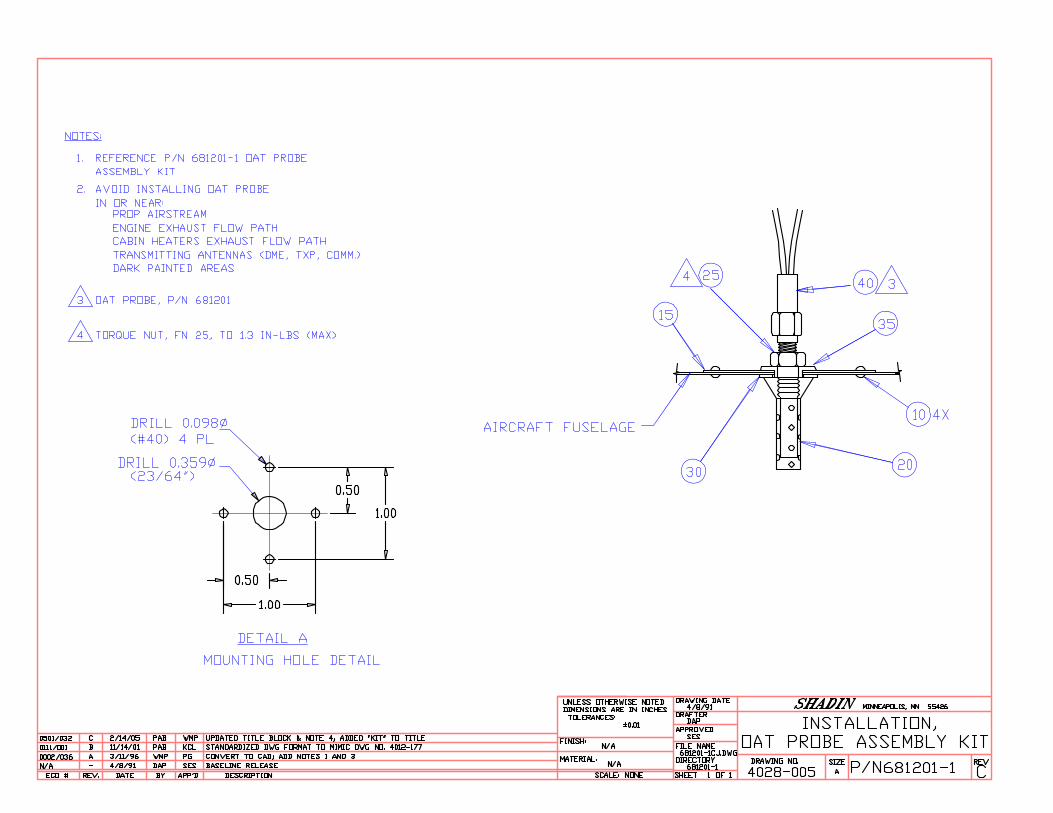
FUEL/AIR DATA COMPUTER Rev: J P/N 962830A-1(A), 962830A-2(A), 962830A-3(A) Page: 5-2 5.4 Mounting the OAT Probe
1. Refer to Drawing 4028-005 and OAT Probe Assy Kit P/N 681201-1. Use the supplied stiffener to support the probe. Keep the probe away from transmitting antennas and static ports of autopilots to void interference.
2. Refer to drawing 4028-A45. The OAT probe power is supplied from (red wire) J1:52. The OAT signal is the white wire from J1:33. At least the signal wire to the ADC2000 should be shielded and terminated at the ADC2000 only.
3. The sun shield must be installed for proper indication of OAT.
4. For single engine installation, avoid mounting the OAT probe on the belly of the aircraft to
avoid erroneous reading due to the presence of hot exhaust gases. 5. Below is an OAT ºC to input current conversion chart for use in testing the OAT Probe.
FUEL/AIR DATA COMPUTER Rev: J P/N 962830A-1(A), 962830A-2(A), 962830A-3(A) Page: 5-3 5.5 Connection to the Fuel Flow Sensor
1. If the aircraft is not equipped with a fuel flow source, refer to the STC covering the installation of the fuel flow transducer on the engine.
2. When connecting to any fuel transducer, Shadin recommends using a 3 conductor, 22
gauge, shielded wire with the shield terminated at the AIR DATA only. 3. Note that for single engines all fuel flow types should use left side inputs only. 4. *Install the transducers according to the engine STC, using Drawing 4028-A46 to connect
the fuel flow transducer to the computer. 5. *If the aircraft is equipped with a digital fuel flow system using transducer (P/N 680501),
use Drawing 4028-A46 (refer to note 1 on that drawing) and the STC drawing covering the installation.
6. Before hooking to an existing fuel system in a turbine or jet application, consult all
installation drawings contained in this manual. 7. *If the aircraft is equipped with a DC fuel flow system, use Drawing 4028-A46 (for P/N
962830A-3(A)) and the STC covering the installation.
8. *If the aircraft is equipped with a sine wave pickup coil type of fuel flow transducer, use
Drawing 4028-A46 (for P/N 962830A-2(A)). 9. Make sure that the system is initialized with the proper transducer K-Factor for a digital or
sine systems and with the proper airframe make and model for the DC fuel flow systems. See the attached tables in section 10.0.
* Consult section 11 for specific aircraft installation wiring drawings.
FUEL/AIR DATA COMPUTER Rev: J P/N 962830A-1(A), 962830A-2(A), 962830A-3(A) Page: 5-4 5.6 Connection to the Heading Source The system is designed to interface with any ARINC-407 heading system (X, Y, Z) with no
effect on the heading system or the bootstrap.
Sandel SN3308
XYZ Heading ARINC
407
FUEL AIR
DATA J1
Collins 328A-2A
2P1
Collins HSI331A
P1
Collins MCS 65
P1
Collins 328A-5
King KI525A
P2
King KSG105
P1
Sperry Gyrosyn Comp.
P1
Sigma-Tek DG
P1 P2
X 7 11 S 25 32 s t L A 25 Y 2 4 T 40 22 v p M B 6 Z 35 3 U 24 12 t k K D 4 H 18 26 V 6 53 r c H E 4 C 35 22 W 5 57 u f J H 4
The C wire (AC common) and the Z wire must be connected together at the source (bootstrap). Refer to Installation Wiring Drawing, 4028-A45, for wiring installation details.
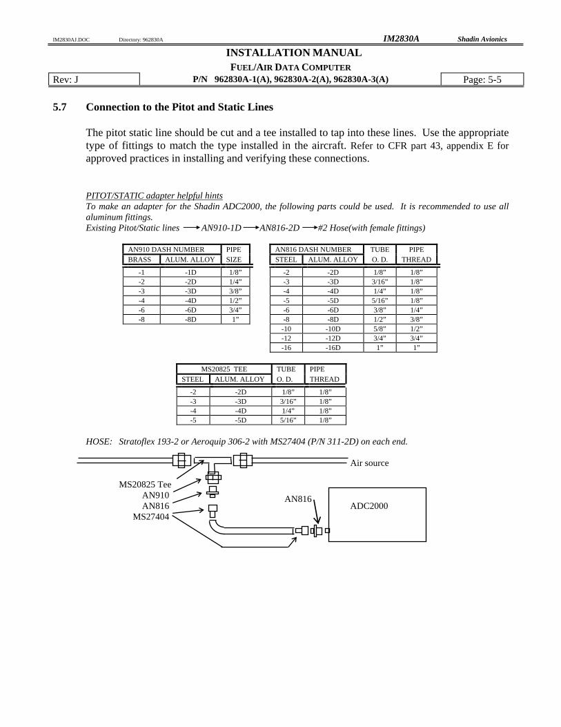
FUEL/AIR DATA COMPUTER Rev: J P/N 962830A-1(A), 962830A-2(A), 962830A-3(A) Page: 5-5 5.7 Connection to the Pitot and Static Lines
The pitot static line should be cut and a tee installed to tap into these lines. Use the appropriate type of fittings to match the type installed in the aircraft. Refer to CFR part 43, appendix E for approved practices in installing and verifying these connections.
PITOT/STATIC adapter helpful hints To make an adapter for the Shadin ADC2000, the following parts could be used. It is recommended to use all
FUEL/AIR DATA COMPUTER Rev: J P/N 962830A-1(A), 962830A-2(A), 962830A-3(A) Page: 5-6 5.8 Connection to the Navigation Management System
1. Use installation wiring diagram 4028-A45 to connect the Fuel AIR DATA Computer's Connector J1 to the navigation management system.
2. A 2 amp. circuit breaker should be used for powering the system. Mark the circuit breaker
by engraving, painting or other approved method.
3. Keep the cables away from power cables, DME and transponder cables.
4. Refer to the specific Nav Receiver Installation Manuals for details.
5. If the ARINC 429 output is used, refer to the digital EFIS or flight management installation manual and sections 2.5.2 – 2.5.4 in this manual.
5.9 Connection to the Altimeter Baro Pot (optional)
1. Use the Installation wiring diagram 4028-A47 to connect the altimeter to J1 of the AIR DATA computer.
2. Remember to select the correct altimeter type in the software configuration. See section 9
in this manual. 5.10 Post Installation Checkout
1. The pitot and static system must be checked for leaks.
2. Operate the Navigation Management System; select the altitude and airspeed pages. Use the static and pitot test system to check the accuracy of the readout in the Navigation Management System pages.
3. Select heading page. Slew compass through 360°. The error should be within +1°.
4. Select the OAT page. Compare to the reported ambient temperature. The error should be
within +2°C.
5. Run the engines and select the fuel flow page. Compare the fuel flow readout with the engine manufacturer's fuel flow charts under the ambient temperature and pressure conditions.
6. Set the Barometric pressure to a known value and verify that the reported barometric
pressure at the Navigational Receiver is that value + 0.01 In.Hg. (if the option is installed)
1. Power the avionics DC buss and the Navigation Management System. 2. After the warm-up period, density altitude and PALT are available. IAS will be available
but will be out of range until actual airspeed is available. Winds aloft will be available if the IAS is greater than 40 Kts and magnetic heading is within 40° of magnetic track.
3. Fuel Flow, Fuel Used, Fuel Remaining, Heading and OAT will be available after power-
up. 4. Refer to the specific Nav Receiver Operator's Manual for page selection of various data.
1. The system requires initialization of K-factor for fuel flow transducers or aircraft model for DC fuel flow sensors. Refer to Table 1 analog for fuel flow and Table 2 or Table 3 for digital or sinewave fuel flow.
2. Refer to the specific Navigational Receiver Operator Manuals for the serial port set up.
FUEL/AIR DATA COMPUTER Rev: J P/N 962830A-1(A), 962830A-2(A), 962830A-3(A) Page: 9-1 9.0 CONFIGURING THE AIR DATA
Part number 962830A-X(A) (X= 1 or 2 or 3) AIR DATA Computer needs to be configured to program it for the particular installation. The procedure contained in this Installation Manual is for software versions 93.00.16 to 93.00.29, 93.00.51 to 93.00.71, 93.00.77, and 93.00.82 and above. There are two methods to accomplish this task. The first method is to follow the procedures as set forth in the 'ADSETUPF User Manual'. The second method is to manually enter the information by performing a ‘Loop-Back’ procedure.
9.1 Configuring with 'ADSETUP User Manual' The ADSETUP User Manual is a configuration utility that allows setting the ADC configuration by running a program on a PC. The PC is connected to the AIR DATA via the serial communication port. See the 'ADSETUP User Manual' for more details.
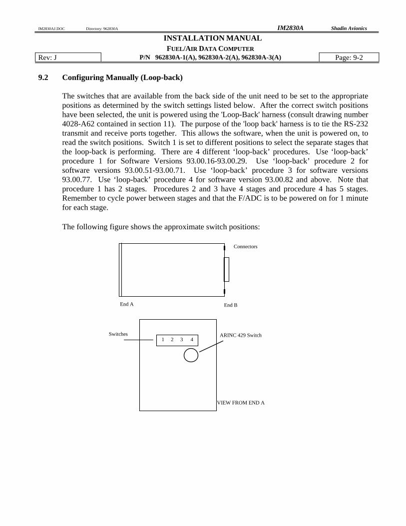
The switches that are available from the back side of the unit need to be set to the appropriate positions as determined by the switch settings listed below. After the correct switch positions have been selected, the unit is powered using the 'Loop-Back' harness (consult drawing number 4028-A62 contained in section 11). The purpose of the 'loop back' harness is to tie the RS-232 transmit and receive ports together. This allows the software, when the unit is powered on, to read the switch positions. Switch 1 is set to different positions to select the separate stages that the loop-back is performing. There are 4 different ‘loop-back’ procedures. Use ‘loop-back’ procedure 1 for Software Versions 93.00.16-93.00.29. Use ‘loop-back’ procedure 2 for software versions 93.00.51-93.00.71. Use ‘loop-back’ procedure 3 for software versions 93.00.77. Use ‘loop-back’ procedure 4 for software version 93.00.82 and above. Note that procedure 1 has 2 stages. Procedures 2 and 3 have 4 stages and procedure 4 has 5 stages. Remember to cycle power between stages and that the F/ADC is to be powered on for 1 minute for each stage.
The following figure shows the approximate switch positions:
Loop-back Procedure 1 for Software Version 93.00.16 - 93.00.29
Stage 0 Loop-back Configuration:
Switch 1 is set to 0 to indicate that the stage 0 loop-back is being performed.
SWITCH 2 Fuel Units and Engine Type:
0 - Gallons Single Engine 1 - Liters " " 2 - Lbs 5.8 " " 3 - Lbs 6.71 " " 4 - Kilograms " " 5 - Lbs 6.5 " " 6 - Lbs 6.3 " " 7 - (not used) " " 8 - Gallons Twin Engine 9 - Liters " " A - Lbs 5.8 " " B - Lbs 6.71 " " C - Kilograms " " D - Lbs 6.5 " " E - Lbs 6.3 " " F - (DO NOT USE)
SWITCH 3 9600 BAUD Loran Input Type:
0 - Trimble 1 - ARNAV 2 - Bendix or IIMorrow Apollo NMS2001, 800, 820 3 - Garmin 4 - Northstar, 9600 BAUD 5 - Foster 6 - IIMorrow 611, 612 and 618 7 - Shadin Flow Meter 8-E - (DO NOT USE) F - Use this position to make selection on SWITCH 4
SWITCH 4 Other Loran Input Type: 0 - Northstar, 1200 BAUD 1 - Foster, 1200 BAUD 2 - IIMorrow 611, 612, 618; 1200 BAUD 3-F - (DO NOT USE)
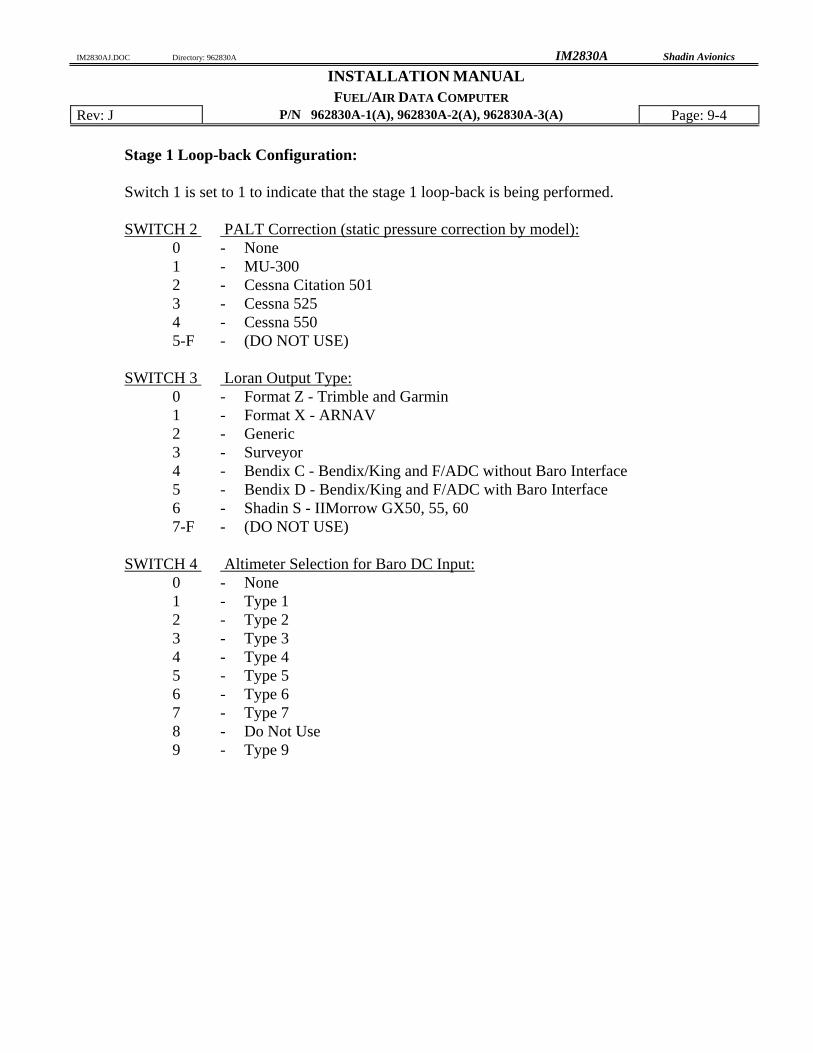
Stage 1 Loop-back Configuration: Switch 1 is set to 1 to indicate that the stage 1 loop-back is being performed. SWITCH 2 PALT Correction (static pressure correction by model):
0 - Format Z - Trimble and Garmin 1 - Format X - ARNAV 2 - Generic 3 - Surveyor 4 - Bendix C - Bendix/King and F/ADC without Baro Interface 5 - Bendix D - Bendix/King and F/ADC with Baro Interface 6 - Shadin S - IIMorrow GX50, 55, 60 7-F - (DO NOT USE)
SWITCH 4 Altimeter Selection for Baro DC Input:
0 - None 1 - Type 1 2 - Type 2 3 - Type 3 4 - Type 4 5 - Type 5 6 - Type 6 7 - Type 7 8 - Do Not Use 9 - Type 9
Type 1: Kollsman PD 44929-935 (done for Cessna 525). Type 2: Bendix/King KEA 130A, and -346. Type 3: ARINC 575-3 specification for ratio to Altitude Correction calculation. Kollsman IDC 28007-427, -429, Kollsman IDC 28704-A1001, -A2001, -A4001, -B4001, -C4001, -D1001, -D2001, -D4001, -D4101, -E2101, -F2101 and -495. Type 4: Kollsman IDC 28711-621 thru 624. Type 5: Kollsman IDC 28007-431, -433, Honeywell (Sperry) BA-141. Type 6: Kollsman IDC 28711-500 series and -600 series. Type 7: Kollsman IDC 28711-065 and -066. Type 8: Reserved for future use (DO NOT USE). Type 9: Aerosonic P/N 102220-1188T, P/N 10420-11968E.
Loop-back Procedure 2 for Software Version 93.00.51 to 93.00.71
Stage 0 Loop-back Configuration: Switch 1 is set to 0 to indicate that the stage 0 loop-back is being performed. SWITCH 2 Fuel Units and Engine Type:
0 - Gallons Single Engine 1 - Liters " " 2 - Lbs 5.8 " " 3 - Lbs 6.71 " " 4 - Kilograms " " 5 - Lbs 6.5 " " 6 - Lbs 6.3 " " 7 - (not used) " " 8 - Gallons Twin Engine 9 - Liters " " A - Lbs 5.8 " " B - Lbs 6.71 " " C - Kilograms " " D - Lbs 6.5 " " E - Lbs 6.3 " " F - (DO NOT USE)
SWITCH 3 9600 BAUD Loran Input Type:
0 - Trimble 1 - ARNAV 2 - Bendix or IIMorrow NMS2001, 800, 820, GX50/55/60, 9600 3 - Garmin 4 - Northstar (1200 or 9600 baud, 1200 is default for Northstar) 5 - Foster 6 - IIMorrow 611, 612 and 618 (1200 baud) 7 - Shadin Flow Meter 8-E - (DO NOT USE) F - Use this position to make selection on SWITCH 4
SWITCH 4 Other Loran Input Type: 0 - Northstar, 1200 BAUD 1 - Foster, 1200 BAUD 2 - IIMorrow 611, 612, 618; 1200 BAUD 3-F - (DO NOT USE)
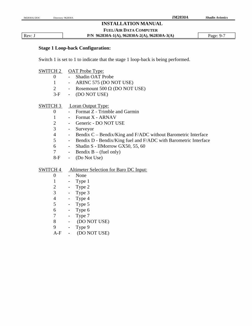
Stage 1 Loop-back Configuration: Switch 1 is set to 1 to indicate that the stage 1 loop-back is being performed. SWITCH 2 OAT Probe Type:
0 - Shadin OAT Probe 1 - ARINC 575 (DO NOT USE) 2 - Rosemount 500 Ω (DO NOT USE) 3-F - (DO NOT USE)
SWITCH 3 Loran Output Type:
0 - Format Z - Trimble and Garmin 1 - Format X - ARNAV 2 - Generic - DO NOT USE 3 - Surveyor 4 - Bendix C – Bendix/King and F/ADC without Barometric Interface 5 - Bendix D - Bendix/King fuel and F/ADC with Barometric Interface 6 - Shadin S - IIMorrow GX50, 55, 60 7 - Bendix B – (fuel only) 8-F - (Do Not Use)
SWITCH 4 Altimeter Selection for Baro DC Input: 0 - None 1 - Type 1 2 - Type 2 3 - Type 3 4 - Type 4 5 - Type 5 6 - Type 6 7 - Type 7 8 - (DO NOT USE) 9 - Type 9 A-F - (DO NOT USE)
Type 1: Kollsman PD 44929-935 (done for Cessna 525). Type 2: Bendix/King KEA 130A, and KEA 346 versions (King P/N 066-3062-XX) XX
= 08 through 11, versions 00 though 07 have no Baro Potentiometer. Type 3: ARINC 575-3 specification for ratio to Altitude Correction calculation. Kollsman IDC 28007-427, -429, Kollsman IDC 28704-A1001, -A2001, -A4001, -B4001, -C4001, -D1001, -
D2001, -D4001, -D4101, -4E2101, -F2101, and -495. Type 4: Kollsman IDC 28711-621 thru 624. Type 5: Kollsman IDC 28007-431, -433, Honeywell (Sperry) BA-141. Type 6: Kollsman IDC 28711-500 series and -600 series. Type 7: Kollsman IDC 28711-065 and -066. Type 8: Reserved for future use (DO NOT USE). Type 9: Aerosonic P/N 102220-1188T, P/N 10420-11968E.
FUEL/AIR DATA COMPUTER Rev: J P/N 962830A-1(A), 962830A-2(A), 962830A-3(A) Page: 9-9 Stage 2 Loop-back configuration: Switch 1 is set to 2 to indicate that the stage 2 loop-back is being performed. SWITCH 2 Fuel Filter Type:
0 - Injector 1 - Carburetor
SWITCH 3 AND SWITCH 4 CORRECTION For SSEC/PSEC Select: F/ADC Software Version:
0 0 - No correction ALL 0 1 - MITSUBISHI MU-300 93.00.29 - and up 0 2 - CESSNA CITATION 500/501 93.00.29 - and up 0 3 - CESSNA 525 93.00.29 - and up 0 4 - CESSNA 550 93.00.29 - and up 0 5 - Citation 560 SN <=259 93.00.29 - and up 0 6 - Citation 560 SN >=260 93.00.29 - and up 0 7 - Citation 650 93.00.29 - and up 0 8 - Sabreliner 65 93.00.29 - and up 0 9 - WestWind 1124A 93.00.29 - and up 0 A - Lear 24 93.00.29 - and up 0 B - Raytheon Hawker HS 125-3A 93.00.29 - and up 0 C - Falcon 20-F 93.00.29 - and up 0 D - Falcon 20-C, D, E 93.00.29 - and up 0 E - Lear 25D 93.00.29 - and up 0 F - Douglas DC-8 93.00.58 - and up 1 0 - Beechjet 400 93.00.63 - and up 1 1 - Boeing 707-321B 93.00.63 - and up 1 2 - Cessna Citation S550 93.00.63 - and up 1 3 - Falcon 10 93.00.63 - and up 1 4 - Falcon 50 93.00.63 - and up 1 5 - Raytheon Hawker HS125-700A 93.00.63 - and up 1 6 - Learjet 35 93.00.63 - and up 1 7 - Learjet 55 93.00.63 - and up 1 8 - Sabreliner 60 (SSEC Only) 93.00.63 - and up 1 9 - Lockheed Jetstar II 93.00.63 - and up 1 A-F - Reserved for future (DO NOT USE)
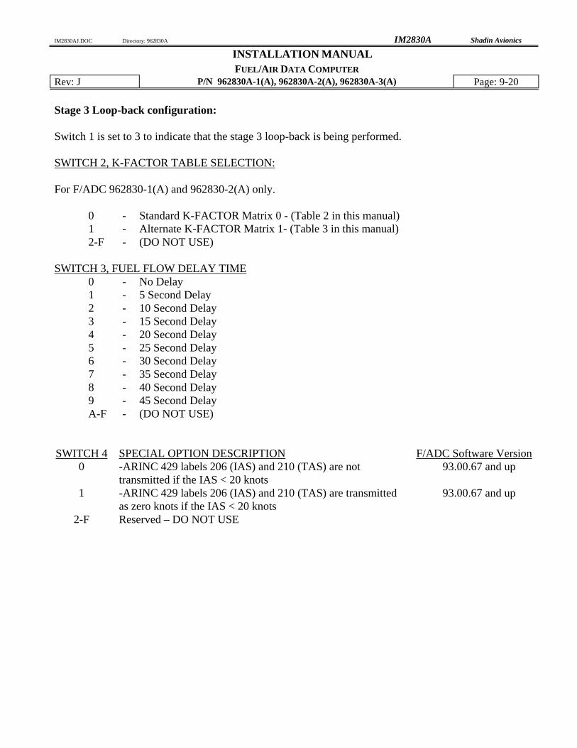
FUEL/AIR DATA COMPUTER Rev: J P/N 962830A-1(A), 962830A-2(A), 962830A-3(A) Page: 9-10 Stage 3 Loop-back configuration: Switch 1 is set to 3 to indicate that the stage 3 loop-back is being performed. SWITCH 2, K-FACTOR TABLE SELECTION: For F/ADC 962830A-1(A) and 962830A-2(A) only.
0 - Standard K-FACTOR Matrix 0 - (Table 2 in this manual) 1 - Alternate K-FACTOR Matrix 1- (Table 3 in this manual) 2-F - (DO NOT USE)
SWITCH 3, FUEL FLOW DELAY TIME
0 - No Delay 1 - 5 Second Delay 2 - 10 Second Delay 3 - 15 Second Delay 4 - 20 Second Delay 5 - 25 Second Delay 6 - 30 Second Delay 7 - 35 Second Delay 8 - 40 Second Delay 9 - 45 Second Delay A-F - (DO NOT USE)
SWITCH 4 SPECIAL OPTION DESCRIPTION F/ADC Software Version
0 -ARINC 429 labels 206 (IAS) and 210 (TAS) are not transmitted if the IAS < 20 knots
93.00.67 and up
1 -ARINC 429 labels 206 (IAS) and 210 (TAS) are transmitted as zero knots if the IAS < 20 knots
Loop-back Procedure 3 for Software Version 93.00.77
Stage 0 Loop-back Configuration: Switch 1 is set to 0 to indicate that the stage 0 loop-back is being performed. SWITCH 2 Fuel Units and Engine Type:
0 - Gallons Single Engine 1 - Liters " " 2 - Lbs 5.8 " " 3 - Lbs 6.71 " " 4 - Kilograms " " 5 - Lbs 6.5 " " 6 - Lbs 6.3 " " 7 - (not used) " " 8 - Gallons Twin Engine 9 - Liters " " A - Lbs 5.8 " " B - Lbs 6.71 " " C - Kilograms " " D - Lbs 6.5 " " E - Lbs 6.3 " " F - (DO NOT USE)
SWITCH 3 9600 BAUD Loran Input Type:
0 - Trimble 1 - ARNAV 2 - Bendix or IIMorrow NMS2001, 800, 820, GX50/55/60, 9600 3 - Garmin 4 - Northstar (1200 or 9600 baud, 1200 is default for Northstar) 5 - Foster 6 - IIMorrow 611, 612 and 618 (1200 baud) 7 - Shadin Flow Meter 8-E - (DO NOT USE) F - Use this position to make selection on SWITCH 4
SWITCH 4 Other Loran Input Type: 0 - Northstar, 1200 BAUD 1 - Foster, 1200 BAUD 2 - IIMorrow 611, 612, 618; 1200 BAUD 3-F - (DO NOT USE)
Stage 1 Loop-back Configuration: Switch 1 is set to 1 to indicate that the stage 1 loop-back is being performed. SWITCH 2 OAT Probe Type:
0 - Shadin OAT Probe 1 - ARINC 575 (DO NOT USE) 2 - Rosemount 500 Ω (DO NOT USE) 3-F - (DO NOT USE)
SWITCH 3 Loran Output Type:
0 - Format Z - Trimble and Garmin 1 - Format X - ARNAV 2 - Generic - DO NOT USE 3 - Surveyor 4 - Bendix C – Bendix/King and F/ADC without Barometric Interface 5 - Bendix D - Bendix/King and F/ADC with Barometric Interface 6 - Shadin S - IIMorrow GX50, 55, 60 7 - Bendix B – (fuel only) 8 - Garmin G 9-F - (DO NOT USE)
SWITCH 4 Altimeter Selection for Baro DC Input: 0 - None 1 - Type 1 2 - Type 2 3 - Type 3 4 - Type 4 5 - Type 5 6 - Type 6 7 - Type 7 8 - (DO NOT USE) 9 - Type 9 A-F - (DO NOT USE)
Type 1: Kollsman PD 44929-935 (done for Cessna 525). Type 2: Bendix/King KEA 130A, and KEA 346 versions (King P/N 066-3062-XX) XX
= 08 through 11, versions 00 though 07 have no Baro Potentiometer. Type 3: ARINC 575-3 specification for ratio to Altitude Correction calculation. Kollsman IDC 28007-427, -429, Kollsman IDC 28704-A1001, -A2001, -A4001, -B4001, -C4001, -D1001, -
D2001, -D4001, -D4101, -4E2101, -F2101, and -495. Type 4: Kollsman IDC 28711-621 thru 624. Type 5: Kollsman IDC 28007-431, -433, Honeywell (Sperry) BA-141. Type 6: Kollsman IDC 28711-500 series and -600 series. Type 7: Kollsman IDC 28711-065 and -066. Type 8: Reserved for future use (DO NOT USE). Type 9: Aerosonic P/N 102220-1188T, P/N 10420-11968E.
FUEL/AIR DATA COMPUTER Rev: J P/N 962830A-1(A), 962830A-2(A), 962830A-3(A) Page: 9-14 Stage 2 Loop-back configuration: Switch 1 is set to 2 to indicate that the stage 2 loop-back is being performed. SWITCH 2 Fuel Filter Type:
0 - Injector 1 - Carburetor
SWITCH 3 AND SWITCH 4 CORRECTION For SSEC/PSEC Select: F/ADC Software Version:
0 0 - No correction ALL 0 1 - MITSUBISHI MU-300 93.00.29 - and up 0 2 - CESSNA CITATION 500/501 93.00.29 - and up 0 3 - CESSNA 525 93.00.29 - and up 0 4 - CESSNA 550 93.00.29 - and up 0 5 - Citation 560 SN <=259 93.00.29 - and up 0 6 - Citation 560 SN >=260 93.00.29 - and up 0 7 - Citation 650 93.00.29 - and up 0 8 - Sabreliner 65 93.00.29 - and up 0 9 - WestWind 1124A 93.00.29 - and up 0 A - Lear 24 93.00.29 - and up 0 B - Raytheon Hawker HS 125-3A 93.00.29 - and up 0 C - Falcon 20-F 93.00.29 - and up 0 D - Falcon 20-C, D, E 93.00.29 - and up 0 E - Lear 25D 93.00.29 - and up 0 F - Douglas DC-8 93.00.58 - and up 1 0 - Beechjet 400 93.00.63 - and up 1 1 - Boeing 707-321B 93.00.63 - and up 1 2 - Cessna Citation S550 93.00.63 - and up 1 3 - Falcon 10 93.00.63 - and up 1 4 - Falcon 50 93.00.63 - and up 1 5 - Raytheon Hawker HS125-700A 93.00.63 - and up 1 6 - Learjet 35 93.00.63 - and up 1 7 - Learjet 55 93.00.63 - and up 1 8 - Sabreliner 60 (SSEC Only) 93.00.63 - and up 1 9 - Lockheed Jetstar II 93.00.63 - and up 1 A-F - Reserved for future (DO NOT USE)
FUEL/AIR DATA COMPUTER Rev: J P/N 962830A-1(A), 962830A-2(A), 962830A-3(A) Page: 9-15 Stage 3 Loop-back configuration: Switch 1 is set to 3 to indicate that the stage 3 loop-back is being performed. SWITCH 2, K-FACTOR TABLE SELECTION: For F/ADC 962830A-1(A) and 962830A-2(A) only.
0 - Standard K-FACTOR Matrix 0 - (Table 2 in this manual) 1 - Alternate K-FACTOR Matrix 1- (Table 3 in this manual) 2-F - (DO NOT USE)
SWITCH 3, FUEL FLOW DELAY TIME
0 - No Delay 1 - 5 Second Delay 2 - 10 Second Delay 3 - 15 Second Delay 4 - 20 Second Delay 5 - 25 Second Delay 6 - 30 Second Delay 7 - 35 Second Delay 8 - 40 Second Delay 9 - 45 Second Delay A-F - (DO NOT USE)
SWITCH 4 SPECIAL OPTION DESCRIPTION F/ADC Software Version
0 -ARINC 429 labels 206 (IAS) and 210 (TAS) are not transmitted if the IAS < 20 knots
93.00.67 and up
1 -ARINC 429 labels 206 (IAS) and 210 (TAS) are transmitted as zero knots if the IAS < 20 knots
Loop-back Procedure 4 for Software Version 93.00.82 +
Stage 0 Loop-back Configuration: Switch 1 is set to 0 to indicate that the stage 0 loop-back is being performed. SWITCH 2 Fuel Units and Engine Type:
0 - Gallons Single Engine 1 - Liters " " 2 - Lbs 5.8 " " 3 - Lbs 6.71 " " 4 - Kilograms " " 5 - Lbs 6.5 " " 6 - Lbs 6.3 " " 7 - (not used) " " 8 - Gallons Twin Engine 9 - Liters " " A - Lbs 5.8 " " B - Lbs 6.71 " " C - Kilograms " " D - Lbs 6.5 " " E - Lbs 6.3 " " F - (DO NOT USE)
SWITCH 3 9600 BAUD Loran Input Type:
0 - Trimble 1 - ARNAV 2 - Bendix or IIMorrow Apollo NMS2001, 800, 820 3 - Garmin 4 - Northstar 5 - Foster 6 - IIMorrow 611, 612 and 618 7 - Shadin Flow Meter 8-E - (DO NOT USE) F - Use this position to make selection on SWITCH 4
SWITCH 4 Other Loran Input Type: 0 - Northstar, 1200 BAUD 1 - Foster, 1200 BAUD 2 - IIMorrow 611, 612, 618; 1200 BAUD 3-F - (DO NOT USE)
Stage 1 Loop-back Configuration: Switch 1 is set to 1 to indicate that the stage 1 loop-back is being performed. SWITCH 2 OAT Probe Type:
0 - Shadin OAT Probe 1 - ARINC 575 (DO NOT USE) 2 - Rosemount 500 Ω (DO NOT USE) 3-F - (DO NOT USE)
SWITCH 3 Loran Output Type:
0 - Format Z - Trimble and Garmin 1 - Format X - ARNAV 2 - Generic 3 - Surveyor 4 - Bendix C - Bendix/King and F/ADC without Baro Interface 5 - Bendix D - Bendix/King and F/ADC with Baro Interface 6 - Shadin S - IIMorrow GX50, 55, 60 7 - Bendix B – (fuel only) 8 - Garmin G 9-F - (Do Not Use)
SWITCH 4 Altimeter Selection for Baro DC Input: 0 - None 1 - Type 1 2 - Type 2 3 - Type 3 4 - Type 4 5 - Type 5 6 - Type 6 7 - Type 7 8 - (DO NOT USE) 9 - Type 9 A - (DO NOT USE) B - Type 11 C-F - (DO NOT USE)
Type 1: Kollsman PD 44929-935 (done for Cessna 525). Type 2: Bendix/King KEA 130A, and KEA 346 versions (King P/N 066-3062-XX) XX
= 08 through 11, versions 00 though 07 have no Baro Potentiometer. Type 3: ARINC 575-3 specification for ratio to Altitude Correction calculation. Kollsman IDC 28007-427, -429, Kollsman IDC 28704-A1001, -A2001, -A4001, -B4001, -C4001, -D1001, -
D2001, -D4001, -D4101, -4E2101, -F2101, and -495. Type 4: Kollsman IDC 28711-621 thru 624. Type 5: Kollsman IDC 28007-431, -433, Honeywell (Sperry) BA-141. Type 6: Kollsman IDC 28711-500 series and -600 series. Type 7: Kollsman IDC 28711-065 and -066. Type 8: Reserved for future use (DO NOT USE). Type 9: Aerosonic P/N 102220-1188T, P/N 10420-11968E. Type 10: Reserved for future use (DO NOT USE). Type 11: IDC P/N KTS B45152 10 410
FUEL/AIR DATA COMPUTER Rev: J P/N 962830A-1(A), 962830A-2(A), 962830A-3(A) Page: 9-19 Stage 2 Loop-back configuration: Switch 1 is set to 2 to indicate that the stage 2 loop-back is being performed. SWITCH 2 Fuel Filter Type:
0 - Injector 1 - Carburetor
SWITCH 3 AND SWITCH 4 CORRECTION For SSEC/PSEC Select: F/ADC Software Version:
0 0 - No correction ALL 0 1 - MITSUBISHI MU-300 93.00.29 - 93.00-51 0 2 - CESSNA CITATION 500/501 93.00.29 - 93.00-51 0 3 - CESSNA 525 93.00.29 - 93.00-51 0 4 - CESSNA 500 93.00.29 - 93.00-51 0 5 - Citation 560 SN <=259 93.00.29 - 93.00-51 0 6 - Citation 560 SN >=260 93.00.29 - 93.00-51 0 7 - Citation 650 93.00.29 - 93.00-51 0 8 - Sabreliner 65 93.00.29 - 93.00-51 0 9 - WestWind 1124A 93.00.29 - 93.00-51 0 A - LearJet 24 93.00.29 - 93.00-51 0 B - Raytheon Hawker HS 125-3A 93.00.29 - 93.00-51 0 C - Falcon 20-F 93.00.29 - 93.00-51 0 D - Falcon 20-C, D, E 93.00.29 - 93.00-51 0 E - LearJet 25D 93.00.29 - 93.00-51 0 F - Douglas DC-8 93.00.58 - 93.00.63 1 0 - Beechjet 400 93.00.63 - and up 1 1 - Boeing 707-321B 93.00.63 - and up 1 2 - Cessna Citation S550 93.00.63 - and up 1 3 - Falcon 10 93.00.63 - and up 1 4 - Falcon 50 93.00.63 - and up 1 5 - Raytheon Hawker HS125-700A 93.00.63 - and up 1 6 - LearJet 35 93.00.63 - and up 1 7 - LearJet 55 93.00.63 - and up 1 8 - Sabreliner 60 (SSEC Only) 93.00.63 - and up 1 9 - Lockheed Jetstar II 93.00.63 - and up 1 A-F - Reserved for future (DO NOT USE)
FUEL/AIR DATA COMPUTER Rev: J P/N 962830A-1(A), 962830A-2(A), 962830A-3(A) Page: 9-20 Stage 3 Loop-back configuration: Switch 1 is set to 3 to indicate that the stage 3 loop-back is being performed. SWITCH 2, K-FACTOR TABLE SELECTION: For F/ADC 962830-1(A) and 962830-2(A) only.
0 - Standard K-FACTOR Matrix 0 - (Table 2 in this manual) 1 - Alternate K-FACTOR Matrix 1- (Table 3 in this manual) 2-F - (DO NOT USE)
SWITCH 3, FUEL FLOW DELAY TIME
0 - No Delay 1 - 5 Second Delay 2 - 10 Second Delay 3 - 15 Second Delay 4 - 20 Second Delay 5 - 25 Second Delay 6 - 30 Second Delay 7 - 35 Second Delay 8 - 40 Second Delay 9 - 45 Second Delay A-F - (DO NOT USE)
SWITCH 4 SPECIAL OPTION DESCRIPTION F/ADC Software Version
0 -ARINC 429 labels 206 (IAS) and 210 (TAS) are not transmitted if the IAS < 20 knots
93.00.67 and up
1 -ARINC 429 labels 206 (IAS) and 210 (TAS) are transmitted as zero knots if the IAS < 20 knots
FUEL/AIR DATA COMPUTER Rev: J P/N 962830A-1(A), 962830A-2(A), 962830A-3(A) Page: 9-21 Stage 4 Loop-back configuration: Switch 1 is set to 4 to indicate that the stage 4 loop-back is being performed. Refer to the OAT probe
calibration certificate for the Ta, Tb, Tc calibration code selection. SWITCH 2, OAT Ta CALIBRATION CODE SELECTION:
0-F - Refer to calibration certificate for “A” code selection 0 to F. SWITCH 3, OAT Tb CALIBRATION CODE SELECTION
0-F - Refer to calibration certificate for “B” code selection 0 to F.
SWITCH 4, OAT Tc CALIBRATION CODE SELECTION
0-F - Refer to calibration certificate for “C” code selection 0 to F. Note: Switch 2, 3, and 4 are set to position 0 (zero), if the OAT probe does not have a calibration code
FUEL/AIR DATA COMPUTER Rev: J P/N 962830A-1(A), 962830A-2(A), 962830A-3(A) Page: 9-22 SELECT NO DELAY
Only under special circumstances should a fuel flow delay time other than “No Delay” be selected. Read the following paragraphs for a description of these special circumstances. On a few aircraft installations which have digital fuel flow and use a very low K-factor (858 pulses per gallon), there has been a problem with the Air Data reporting a large jump in fuel used as well as a corresponding decrease in fuel remaining at engine startup. This is not considered to be a Shadin Air Data problem, but rather has been defined as an aircraft problem involving noise on the digital fuel flow signal. A solution for this problem is to use the Air Data fuel flow delay feature. This feature suppresses the fuel flow (and its affect on fuel used and remaining) for a startup delay time each time the engine starts. Fuel flow delay time is selectable in the Air Data loop-back mode, with selections of 0, 5, 10, 15, 20, 25, 30, 35, 40, and 45 seconds delay available. If a fuel flow delay is needed, start by reconfiguring the ADC to use a large delay (i.e. 45 seconds). If the large fuel flow mitigated the problem try reducing the delay until the problem returns. Then use the least amount of fuel flow delay that suppresses the problem. When a fuel flow delay time is selected, the Air Data checks for fuel flow below 15 pph. If the fuel flow is below 15 pph, the Air Data considers the engine to be off and returns a fuel flow of 0. Then as soon as the fuel flow exceeds 15 pph, the Air Data continues to return a fuel flow of 0 until the delay time has expired. In a twin engine, the Air Data zeroes both fuel flows during the startup delay for each engine. SPECIAL OPTIONS
Only under special circumstance should SPECIAL OPTION 1 be selected. Read the following paragraphs for a description of the special circumstance.
Because the IAS range on the AIR DATA computer is valid from 20 to 350 knots ARINC 429 labels 206 and 210 are transmitted with NCD status and stop being transmitted almost simultaneously if the IAS is less than 20 knots. In order to interface with certain avionics equipment which exhibit warnings if a valid IAS or TAS label is not received, SPECIAL OPTION 1 was implemented. When the AIR DATA computer is configured with SPECIAL OPTION 1 the ARINC 429 labels 206 and 210 are transmitted with OK status and a value of zero knots if the actual IAS is less than 20 knots.
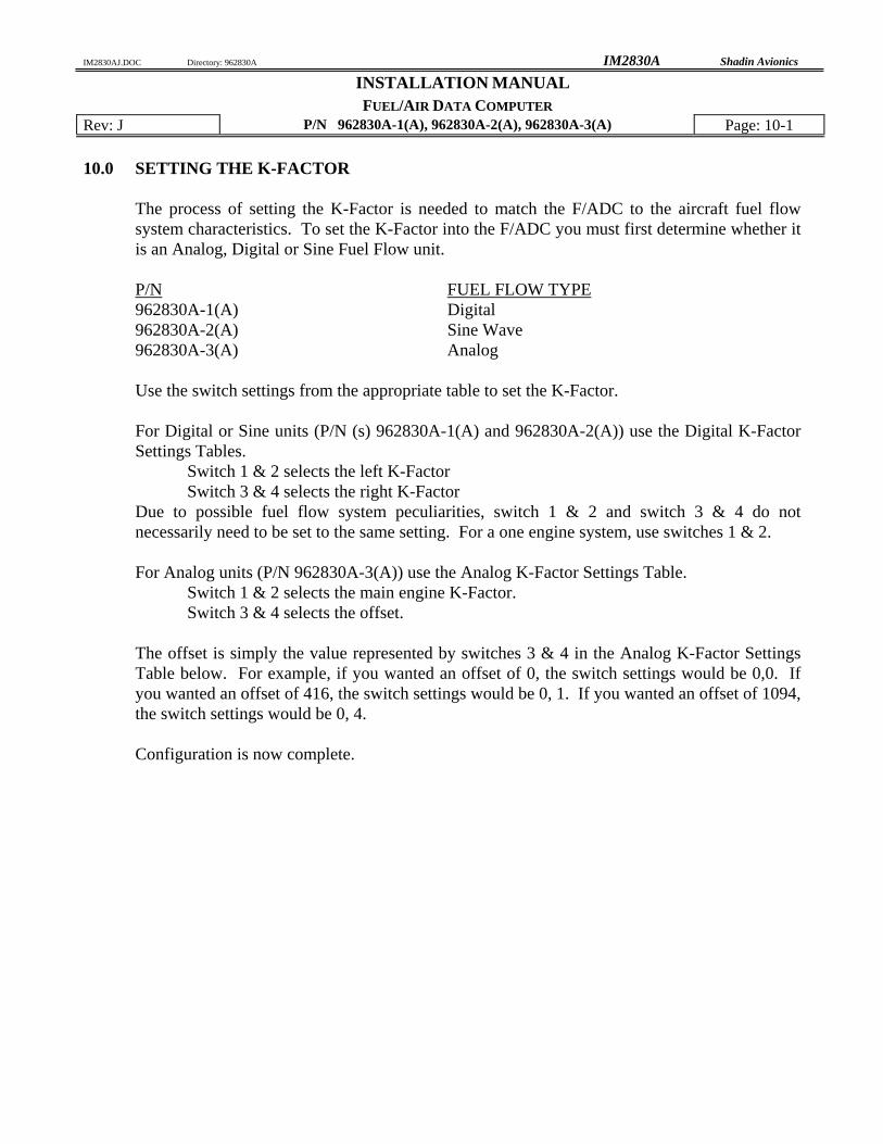
The process of setting the K-Factor is needed to match the F/ADC to the aircraft fuel flow system characteristics. To set the K-Factor into the F/ADC you must first determine whether it is an Analog, Digital or Sine Fuel Flow unit. P/N FUEL FLOW TYPE 962830A-1(A) Digital 962830A-2(A) Sine Wave 962830A-3(A) Analog Use the switch settings from the appropriate table to set the K-Factor. For Digital or Sine units (P/N (s) 962830A-1(A) and 962830A-2(A)) use the Digital K-Factor Settings Tables.
Switch 1 & 2 selects the left K-Factor Switch 3 & 4 selects the right K-Factor
Due to possible fuel flow system peculiarities, switch 1 & 2 and switch 3 & 4 do not necessarily need to be set to the same setting. For a one engine system, use switches 1 & 2. For Analog units (P/N 962830A-3(A)) use the Analog K-Factor Settings Table.
Switch 1 & 2 selects the main engine K-Factor. Switch 3 & 4 selects the offset.
The offset is simply the value represented by switches 3 & 4 in the Analog K-Factor Settings Table below. For example, if you wanted an offset of 0, the switch settings would be 0,0. If you wanted an offset of 416, the switch settings would be 0, 1. If you wanted an offset of 1094, the switch settings would be 0, 4. Configuration is now complete.
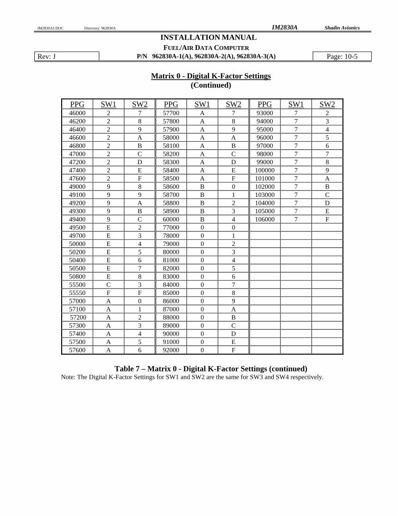
PPG SW1 SW2 PPG SW1 SW2 PPG SW1 SW2 860 D D 8800 5 0 15300 E F 5000 6 B 9000 5 1 18000 3 0 5050 6 C 9200 5 2 18200 3 1 5100 6 D 9400 5 3 18400 2 2 5150 6 E 9600 5 4 18600 3 3 5200 6 F 9800 5 5 18800 3 4 5250 7 0 10000 5 6 19000 3 5 5300 7 1 10100 5 7 19200 3 6 5600 6 0 10200 5 8 19400 3 7 5650 6 1 10300 5 A 19600 3 8 5700 6 2 10400 5 B 19800 3 9 5750 6 3 10500 5 C 20000 3 A 5800 6 4 10600 5 D 20200 3 B 5850 6 5 10700 5 E 20400 3 C 5900 6 6 10800 5 F 20600 3 D 5950 6 7 10900 D 6 20800 3 E 6000 6 8 11000 D 7 21000 3 F 6380 C B 11100 D 8 21200 4 0 6400 C C 11200 D 9 21400 4 1 6420 C D 11300 D A 21600 4 2 6440 C E 11400 D B 21800 4 3 6460 C F 11500 D C 22000 4 4 6480 D 0 14500 D E 22200 4 5 6500 D 1 14600 D F 22400 4 6 6520 D 2 14700 E 9 22600 4 7 6540 D 3 14800 E A 22800 4 8 6560 D 4 14900 E B 23000 4 9 6580 D 5 15000 E C 23200 4 A 6660 6 A 15100 E D 23400 4 B 7640 5 9 15200 E E 23600 4 C
Table 7 – Matrix 0 - Digital K-Factor Settings
Note: The Digital K-Factor Settings for SW1 and SW2 are the same for SW3 and SW4 respectively.
PPG SW1 SW2 PPG SW1 SW2 PPG SW1 SW2 23800 4 D 29800 F B 40000 9 4 24000 4 E 30000 F C 40200 9 5 24200 4 F 30200 F D 40400 9 6 24400 B A 30400 F E 40600 9 7 24600 B B 33800 6 9 40800 9 D 24800 B C 37000 B 9 41000 9 E 25000 B D 37200 B 8 41200 9 F 25200 B E 37400 B 7 41400 1 0 25400 B F 37600 B 6 41600 1 1 25600 C 0 37800 B 5 41800 1 2 25800 C 1 38000 8 0 42000 1 3 26000 C 2 38100 8 1 42200 1 4 26200 C 4 38200 8 2 42400 1 5 26400 C 5 38300 8 3 42600 1 6 26600 C 6 38400 8 4 42800 1 7 26800 C 7 38500 8 5 43000 1 8 27000 C 8 38600 8 6 43200 1 9 27200 C 9 38700 8 7 43400 1 A 27400 C A 38800 8 8 43600 1 B 27600 F 0 38900 8 9 43800 1 C 27800 F 1 39000 8 A 44000 1 D 28000 F 2 39100 8 B 44200 1 E 28200 F 3 39200 8 C 44400 1 F 28400 F 4 39300 8 D 44600 2 0 28600 F 5 39400 8 E 44800 2 1 28800 F 6 39500 8 F 45000 2 2 29000 F 7 39600 9 0 45200 2 3 29200 F 8 39700 9 1 45400 2 4 29400 F 9 39800 9 2 45600 2 5 29600 F A 39900 9 3 45800 2 6
Table 7 – Matrix 0 - Digital K-Factor Settings (continued)
Note: The Digital K-Factor Settings for SW1 and SW2 are the same for SW3 and SW4 respectively.
PPG SW1 SW2 PPG SW1 SW2 PPG SW1 SW2 46000 2 7 57700 A 7 93000 7 2 46200 2 8 57800 A 8 94000 7 3 46400 2 9 57900 A 9 95000 7 4 46600 2 A 58000 A A 96000 7 5 46800 2 B 58100 A B 97000 7 6 47000 2 C 58200 A C 98000 7 7 47200 2 D 58300 A D 99000 7 8 47400 2 E 58400 A E 100000 7 9 47600 2 F 58500 A F 101000 7 A 49000 9 8 58600 B 0 102000 7 B 49100 9 9 58700 B 1 103000 7 C 49200 9 A 58800 B 2 104000 7 D 49300 9 B 58900 B 3 105000 7 E 49400 9 C 60000 B 4 106000 7 F 49500 E 2 77000 0 0 49700 E 3 78000 0 1 50000 E 4 79000 0 2 50200 E 5 80000 0 3 50400 E 6 81000 0 4 50500 E 7 82000 0 5 50800 E 8 83000 0 6 55500 C 3 84000 0 7 55550 F F 85000 0 8 57000 A 0 86000 0 9 57100 A 1 87000 0 A 57200 A 2 88000 0 B 57300 A 3 89000 0 C 57400 A 4 90000 0 D 57500 A 5 91000 0 E 57600 A 6 92000 0 F
Table 7 – Matrix 0 - Digital K-Factor Settings (continued)
Note: The Digital K-Factor Settings for SW1 and SW2 are the same for SW3 and SW4 respectively.
Matrix 1 - Alternate Digital K-Factor Setting Table (software version 93.00.61+)
PPG SW1 SW2 PPG SW1 SW2 PPG SW1 SW2 200 1 0 1940 8 0 16100 4 E 400 1 1 2000 3 D 16300 4 F 440 1 2 2200 3 E 16500 5 0 490 1 3 2400 3 F 16600 5 1 510 1 4 2600 4 0 16800 5 2 520 1 5 2800 4 1 17000 5 3 530 1 6 3000 4 2 17200 5 4 540 1 7 3200 4 3 17400 5 5 550 1 8 3400 4 4 17600 5 6 560 1 9 3600 4 5 17800 5 7 570 1 A 3610 0 0 30600 6 3 580 1 B 3650 0 1 30800 6 4 590 1 C 3690 0 2 31000 6 5 600 1 D 3730 0 3 31200 6 6 610 1 E 3760 0 4 31400 6 7 620 1 F 3800 0 5 31600 6 8 630 2 0 3800 4 6 31800 6 9 640 2 1 3840 0 6 32000 6 A 650 2 2 3880 0 7 32200 6 B 660 2 3 3920 0 8 32400 6 C 670 2 4 3960 0 9 32600 6 D 680 2 5 4000 0 A 32800 6 E 690 2 6 4000 4 7 33000 6 F 700 2 7 4040 0 B 33200 7 0 710 2 8 4080 0 C 33400 7 1 720 2 9 4120 0 D 33600 7 2 730 2 A 4160 0 E 34000 7 3 740 2 B 4200 0 F 34200 7 4 750 2 C 4200 4 8 34400 7 5 760 2 D 4400 4 9 34600 7 6 770 2 E 4700 4 A 34800 7 7 780 2 F 11700 5 8 35000 7 8 790 3 0 11900 5 9 35200 7 9 800 3 1 12100 5 A 35400 7 A 810 3 2 12400 5 B 35600 7 B 820 3 3 12600 5 C 35800 7 C 840 3 4 12800 5 D 36000 7 D 850 3 5 13000 5 E 36400 7 E 880 3 6 13500 5 F 36800 7 F 900 3 7 14000 6 0
1000 3 8 14200 6 1 1200 3 9 14400 6 2 1400 3 A 15500 4 B 1600 3 B 15700 4 C 1800 3 C 15900 4 D
Table 8 – Matrix 1 - Alternate Digital K-Factor Setting (software version 93.00.61+) Note: The Digital K-Factor Settings for SW1 and SW2 are the same for SW3 and SW4 respectively.
B. LOCAl10NS 02117047 D 37"1703 PAS BAL -r7.501"'>D1M WAS -7,303- .
9809/013 C 9/25/98' DlR KCL .11:10 AND .11:4 NOTED AS GROUNDS 98M/028 . B 04/08/98 SRB KCL UPDATE PINOUT 97047038 A 4/7:1/97 AM PC ADDED MS4l FOR MAliNe CONNECTOR P1
RIGHT SIDE (7.1)
¥-SYNCHRO INPUT
YJEW
J1 PINOUT 20. RX, RS422 <:~) & 21. TX, RS232 ~
22. TX, ARINC 4298 2'3. GROUND 24. RIGHT FF SIGNAL + 25. N/C26. LEFT FF SIGNAL 27. N/C 28. N/C 29. N/C 30. N/C 31. N/C 32. N/C 33. OAT SIGNAL 34. N/C 3,5. HEADING COMMON 26 36. TX, RS422 (+)& 37. N/C 38. RX. RS422 (+)&
PAS ~ REDRAWN' ~CTm P1TOT7STAllC LABa. lOCAllONS I...... "f..~0504 ~ E "fT"""VoI
1-(7.150)' DIM WAS---7.3030211) 047 3/11/03 PASD SAL INSTALLATI ON,APPROVEDO[R91"25/98 I<d9809 013 C J1:10 AND J1:4 HOlED AS CROUNOS SES ADC 2000, DC FF, MS CONN.·9, 04J08/G8 SR89804 ID2B I<a. UPDATE PINOUT ~~J.D~'472:1]97 AAA ' PO ADDED Mg'FM MAnNG CONNECTOR P19704 A038
7 SELECT POVER (OUTPUT)10.24) 8 +1:4 TO 28 V DC POVER IN
9 N.C. (3.05)
10 SIGNAL GROUND
RS422 FROM SHADIN ADC11 RX+~ 12 RS422 RX- (USE RS-232 OR RS-422}
RS232 RX NOT BOTH)13
, VEIGHTl 8 oz. POW'ER CONSUMPTION' '210 1'\0.. @ 28v DC
~~~~~ ~~ . n~,r;l.;n: SHALJIN t.lINNEAPOu5. UN 55426
TtURAHCES:x.~: t8:~f :' INSTALLATION, SERIAL TO : PO ARGUS 5000/7000 CONVERlER..,..--------'r"'--f0501/032· B PAS ,.,., UPDATED 1T1l.E BLOaC: -cotVERlER WAS'l».tlR- " MIA 'F§f~WGI- ';'"- .......- .
9801)025 .A to'i?798 DUD. PO ADDED· NOlE 7 CORREC,JED HEIGHT. PRCMDED Sl:4AD1N PIN FClR t.lAllNO CONN. MAlERlAL: DIR£C1tJRY DRA'lNG NO. t (' / JREVSl2E 97rT1 023 - 71' 5/97 PAS .PG BASEUHE RElL\SE' N/A 9J7000...:03 4070 005 ,. P N 937000-03, B 'l:'m. I R£V. U.n: RY IAPP"D, SCALE' NONE ISH~ IOF "
F'UEL2 I SIG + ~-----(=f---~ 24 I R. SIGNAL +F'LO'J
~ I
LEF'T ENGINE IA
F'F' INDICATOR
ill I E
RAGEN PIN 3265013-0601
23 GROUND ~UND I------A----I 7 I R. SIGNAL
I------~--_l 131 R, SIGNAL +
141 L. SIGNAL
15 I L. SIGNAL +
RAGEN PIN 3265013-1201
J1
F'LO'W SIGNAL ~OM F'LO\lMETER 'E F'LO'J SIGNAL TO TOTAUZER G
ALT fLO\l SIGNAL TO TOTALIZER J " +28 VDC INPUT B
REF' SUPPLY TO TOTALIZER F' REF' SUPPLY TO 'F'LO\lMETER C
28 VDC RETURN A SIGNAL RETURN F'ROM F'LO\lMETER D
SIGNAL RETURN TO TOTALIZER H CASE GROUND K
LEF"T -:---'-T---"'I26 I L. SIGNAL 9 I SIG -, ENGINE
, FUEL ----...-.---.. 12 I L. SIGNAL +I 10 1SIG + F'LO'"> Jl
F'LO\l SIGNAL F'ROM F"LD~HETER E F'LD\I SIGNAL TO TOTALIZER G
INTERNA~ TEST POINT J +28 VDC INPUT B
REF' , SUPPLY TO TOTALlZER F' REf SUPPLY TO F'LO\lHETER C
28 VDC RETURN A INTERNAL TEST POINT D
SIGNAL RETURN TD TOTALIZER H CASE GROUND K
t:!IJIES!. '
RAGEN PIN 3265013-0801
Jl
F"LO'" SIGNAl:. FROM FLO"'MET£R E FLO'" SIGNAL TO TOTALIZER G
ALT FLO\l SIGNAL TO TOTALIZER J +28 VDC iNPUT B
REF' SUPPLy'TO TOTALIZER F' REF' SUPPLY TO F'LO\lMETER C
28 VDC RETURN A SIGNAL RETURN F'ROM F'L..O'JMETER D'
SIGNAL RETURN TO TOTALIZER H GASE GROUND K
&FDR.' AIRCRAFT WITH THE FOLLOWING INDICATOR/TRANSMITTERSJ SEE TABLE FOR INDICATOR \JIRING. INDICATOR PART NO. (RAGEN) 3265013-0601 INDlf;:ATDR PART NO. (RAGEN) 3265013-0801
&SET AIRDATA' SWITCHES AS FDLLO\'1'SJ ~W'l,
d~}R[]GRAM DIGIDATA FOR LEFT K-FACTOR' = PPGI LEFT OFFSET = RIGHT OFFSET = O.
w/TRANSMITTER PARr NO. (RAGEN) 3268011-0101. + 3265013-1201 w/TRANSMITTER PART NO'. (RAGEN) TFF-2'905-~ DR PIPER PIN 489-487.
= 11 SW'2 = 1~ S\J3 = 01 SW'4 = O.
RIGHT K-FACTOR = 4~1160'
IIIR~~/~DATE S.HADIlV I4IM£APII.lS MN ~ IllKAtnw'nuc,' , INSTALLATION W'lRING I f lADe-COOl 2000 . DR DIGIDATA 'WITH DC FF PIPERADD JND 326S013-0801 ..5011006 c :u.E.~EJU CHEYENNE PA31TI-JH ADD IN» 326:lO13-1201 XMTR lFF'-290S-9 m NOTE L1/31/00JOV01& B
........ -..c9CJ,.DVG ADD PINS 96283M-3-S-5. 962830-3-S-51/20/99 DMD Ka..901/015 Ii DJRECTDRY8081012' IJMD ICQ.snr38' BASE1.1NE REl.EAS'E DRAVlNG NO. ISIZE'(I' 4028" 4028 A29 A PIN 1['RY IAPP'D I N[ T SCAI...£ ,~F' I nF'ECD • IREV. nATF'
PC900-)(A)()()()(pH~P~--(1-8). (A..), O. (CU!MDtfLAT FAC()
- L + K
&&
INDICATORS ARE NOT LISTED BUT MAY BE INTERFACED. CALL SHADIN "TECH SUPPORT IF YOU DO NOT SEE, THE PARt: NUMBER OF YOUR INDICATOR LISTED. INDICATOR PART NUMBERS POSSESSING A PREfiX OF "PC900-" ARE XOTECHNOLOGIES TYPE INDICATORS. THE LAST DIGIT REPRESENTS THE INPICATOR AUXILIARY RATE OUTPUT (1 NUMBER). SHADIN SUPPORTS THE "-1" MODELS ONLY.
& XOTECHNOLOGIES INDICATOR P/N PC900-XAXXXXPH-XXO IS NOT SU,PPORTED. THE AUXILIARY RATE OUTPUT OF THIS UNIT IS 0-1 rnA. INDICATOR PINS THAT END WITH A "-XX2" WILL ENCOUNTER A DEGRADATlON IN PERFORMANCE DUE TO THE AUX. RATE OUTPUT OF 0-5.333 \lDC. INDICATOR P/NS ENDING WITH, AN "." ARE UNKNOWN.
.&. THE FOLLOwiNG XOTECH'NOLOGIES INDICATOR P/NS POSSESS A K-FACTOR KNOWN TOSHADIN:
ADC200/2000' SWITCH SETTlNGS PART, NUMBER K-FACTORIOFfSET AUX RATE QUJPUT s:m SW2 SWJ SYM
1. THIS INSTALLATION APPLICABLE TO AIRCRAFT W'ITH J.E,T, FUEL MODULE PART NUMBER 542-1158-02 ONLY, J,E,To MODULE NOS, 542-1158-01 MAY BE CHANGED TO 542-1158-02 BY J.E,T. SB542-1158-7A.
2. K-FACTOR IS 860.
&-. SET FIADC SW'ITCHES AS FOLLOW'SJ SW'l=D) SW'2=D, SW'3=D, SW'4=D,
937000-03 IN NAVIGATIONAL RECEIVERS SERIAL ·DATA INPUT.
& CONSUL T DRA\JING NUMBER 4070-005 FOR \lIRING STRAPPING INFORMATION.
~ 10009100:5 B 9/18/00 PAB EDJ TDP LEFT 'J!' VAS 'J2' 19901/015 A .1/20/99 IIMD KD. ADD PIN 962830/..-1-..S-5 -2-S-S -3-S-5 98091U13 - 9/25/98 LR Ka. BASELINE RELEASE ..mLt ~ ~ M .~JJ ~
PARALLEL \11TH
AND
..
-.t!!ll.l!l~
EVENTIDE ARGUS PIN 5000 PIN 7000
,.. 16 RS232 INPUT
~ n 4 I RS232 INPUT
"
•
HI
LO\J
IDRA-".~~J~ATE: I - SHADIN MINNEAPm.IS,1oIM 55426
:::D INSTALLAnON WIRING, F/ ADC 2000 HS CONN AND
If~a.. SHAD IN CONVERTER TO EVENTIDE ARGUS. .f028-:t'iJ,DVG DIRECTORY~:I]JfT