Installation and Commissioning of the Machine A complete working system is composed by laser engraving machine, the exhaust fan, air pump, water pump, water tank, exhaust pipe, data transmission lines and so on. According to the needs, the users can configure the computers, printers, scanners and so on by themselves. I. 2 Installation and Adjusting Steps 1. Laser Tube Installation As the laser glass is fragile goods, the laser tube should be packed separately in order to ensure its safety during the transportation. So the users must install the laser tube before machine installation and commissioning. Laser tube should be mounted on the back of the machine, open the protective cover of laser tube; you can see the two Vee-blocks. As shown in Fig. F2-1: F2-1 Put the light-emitting window (low-voltage end) of laser tube with the same side of No.1 reflector mirror on the Vee-blocks carefully, and then latch on the rubber strip on the Vee-blocks wear of laser tube, fix laser tube well. As shown in Fig. F2-2:
Transcript
Installation and Commissioning of theMachine A complete working system is composed by laser engraving machine, the exhaust
fan, air pump, water pump, water tank, exhaust pipe, data transmission lines and
so on. According to the needs, the users can configure the computers, printers,
scanners and so on by themselves.
I. 2 Installation and Adjusting Steps 1. Laser Tube Installation
As the laser glass is fragile goods, the laser tube should be packed separately in
order to ensure its safety during the transportation. So the users must install the
laser tube before machine installation and commissioning.
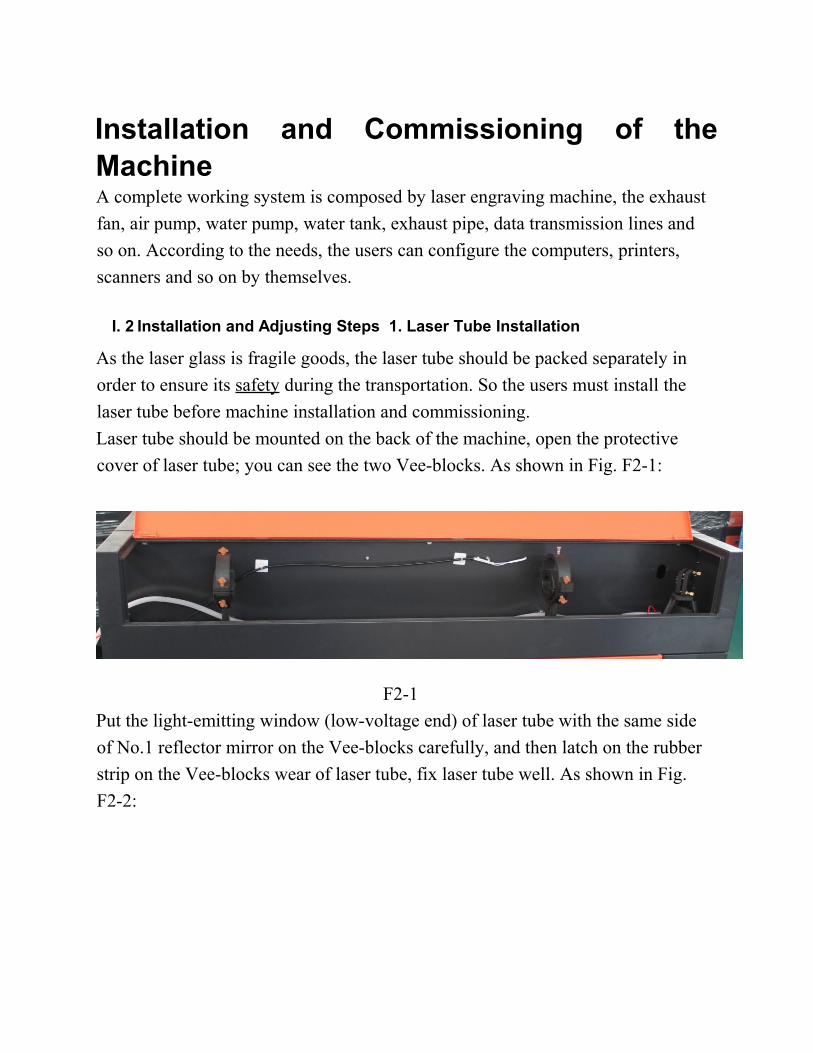
Laser tube should be mounted on the back of the machine, open the protective
cover of laser tube; you can see the two Vee-blocks. As shown in Fig. F2-1:
F2-1
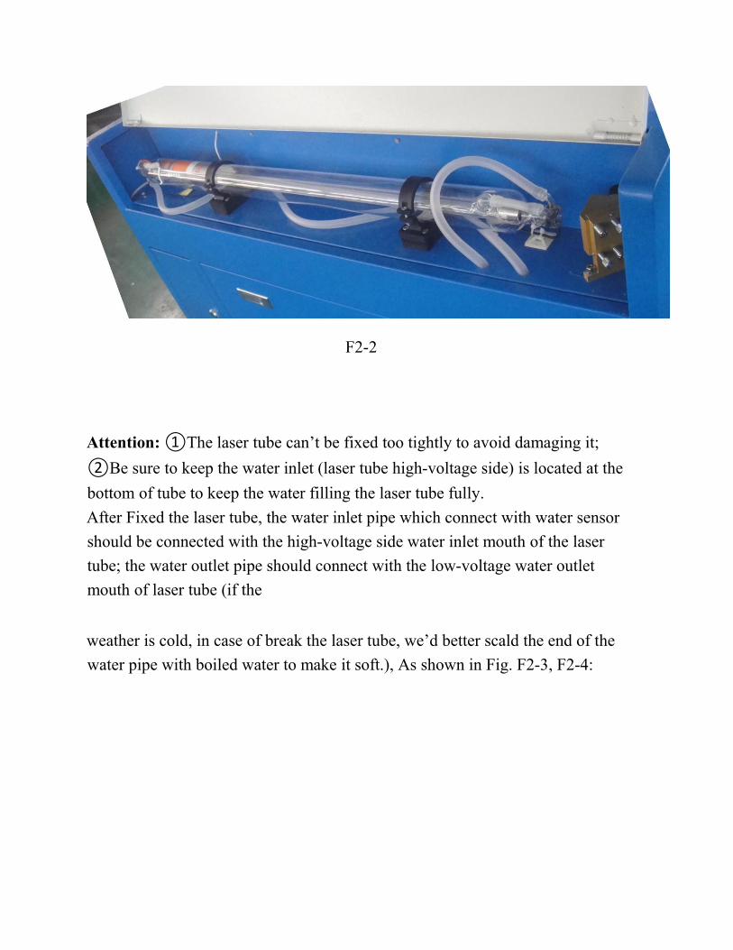
Put the light-emitting window (low-voltage end) of laser tube with the same side
of No.1 reflector mirror on the Vee-blocks carefully, and then latch on the rubber
strip on the Vee-blocks wear of laser tube, fix laser tube well. As shown in Fig.
F2-2:
F2-2
Attention: ①The laser tube can’t be fixed too tightly to avoid damaging it;
②Be sure to keep the water inlet (laser tube high-voltage side) is located at the
bottom of tube to keep the water filling the laser tube fully.
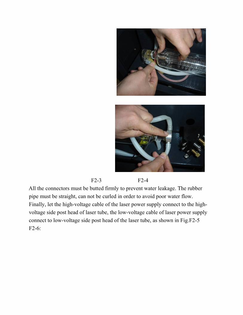
After Fixed the laser tube, the water inlet pipe which connect with water sensor
should be connected with the high-voltage side water inlet mouth of the laser
tube; the water outlet pipe should connect with the low-voltage water outlet
mouth of laser tube (if the
weather is cold, in case of break the laser tube, we’d better scald the end of the
water pipe with boiled water to make it soft.), As shown in Fig. F2-3, F2-4:
F2-3 F2-4
All the connectors must be butted firmly to prevent water leakage. The rubber
pipe must be straight, can not be curled in order to avoid poor water flow.
Finally, let the high-voltage cable of the laser power supply connect to the high-
voltage side post head of laser tube, the low-voltage cable of laser power supply
connect to low-voltage side post head of the laser tube, as shown in Fig.F2-5
F2-6:
F2-5 F2-6
For security, please seal the post head of the high voltage side and low voltage
with silicon gel.
2. Water Pump Installation
Please fill pure water into the water tank (the water level should be higher than
the pump at least). Let the water pump outlet connect to water inlet of the
machine, using another piece of water pipe connect to the water outlet of the
machine ,and put the other side of this water pipe into the water to complete the
circulating water piping connection. As shown in Fig.F2-7, F2-8:
F2-7 F2-8
Connect the water pump power supply, at this time we can see that the laser tube
is gradually filled with water. If the water can through the water outlet pipe
smoothly, it shows that the pump is working properly.
In order to ensure the cooling water flow of the laser tube normally, a water
protection sensor is installed in the water recycling system, when water pumps
working poor or abnormal, the laser engraving machine will come into the
protection state
automatically. Then the laser tube will not emit the laser light. Therefore, in the
course of routine maintenance, you should pay attention to the clean water pumps
and water pipes.
3. Installation of Air Pump
Make the air outlet of the pump connected to the air inlet of the engraving
machine with air pipe; ensure the outlet can vent air normally after turn on the
power. As shown in Fig. F2-9, F2-10:
F2-9 F2-10
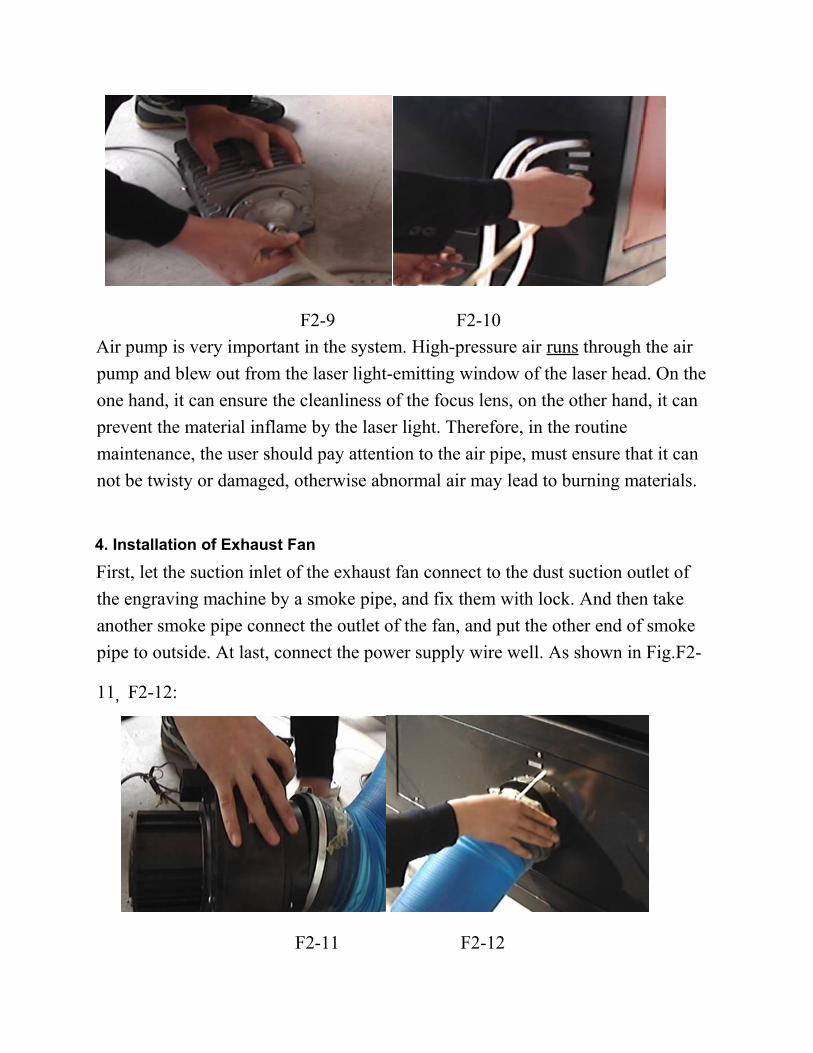
Air pump is very important in the system. High-pressure air runs through the air
pump and blew out from the laser light-emitting window of the laser head. On the
one hand, it can ensure the cleanliness of the focus lens, on the other hand, it can
prevent the material inflame by the laser light. Therefore, in the routine
maintenance, the user should pay attention to the air pipe, must ensure that it can
not be twisty or damaged, otherwise abnormal air may lead to burning materials.
4. Installation of Exhaust Fan
First, let the suction inlet of the exhaust fan connect to the dust suction outlet of
the engraving machine by a smoke pipe, and fix them with lock. And then take
another smoke pipe connect the outlet of the fan, and put the other end of smoke
pipe to outside. At last, connect the power supply wire well. As shown in Fig.F2-
11,F2-12:
F2-11 F2-12
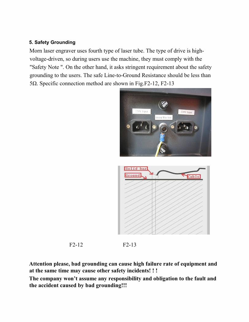
5. Safety Grounding
Morn laser engraver uses fourth type of laser tube. The type of drive is high-
voltage-driven, so during users use the machine, they must comply with the
"Safety Note ". On the other hand, it asks stringent requirement about the safety
grounding to the users. The safe Line-to-Ground Resistance should be less than
5Ω. Specific connection method are shown in Fig.F2-12, F2-13
F2-12 F2-13
Attention please, bad grounding can cause high failure rate of equipment andat the same time may cause other safety incidents! ! !
The company won’t assume any responsibility and obligation to the fault and the accident caused by bad grounding!!!
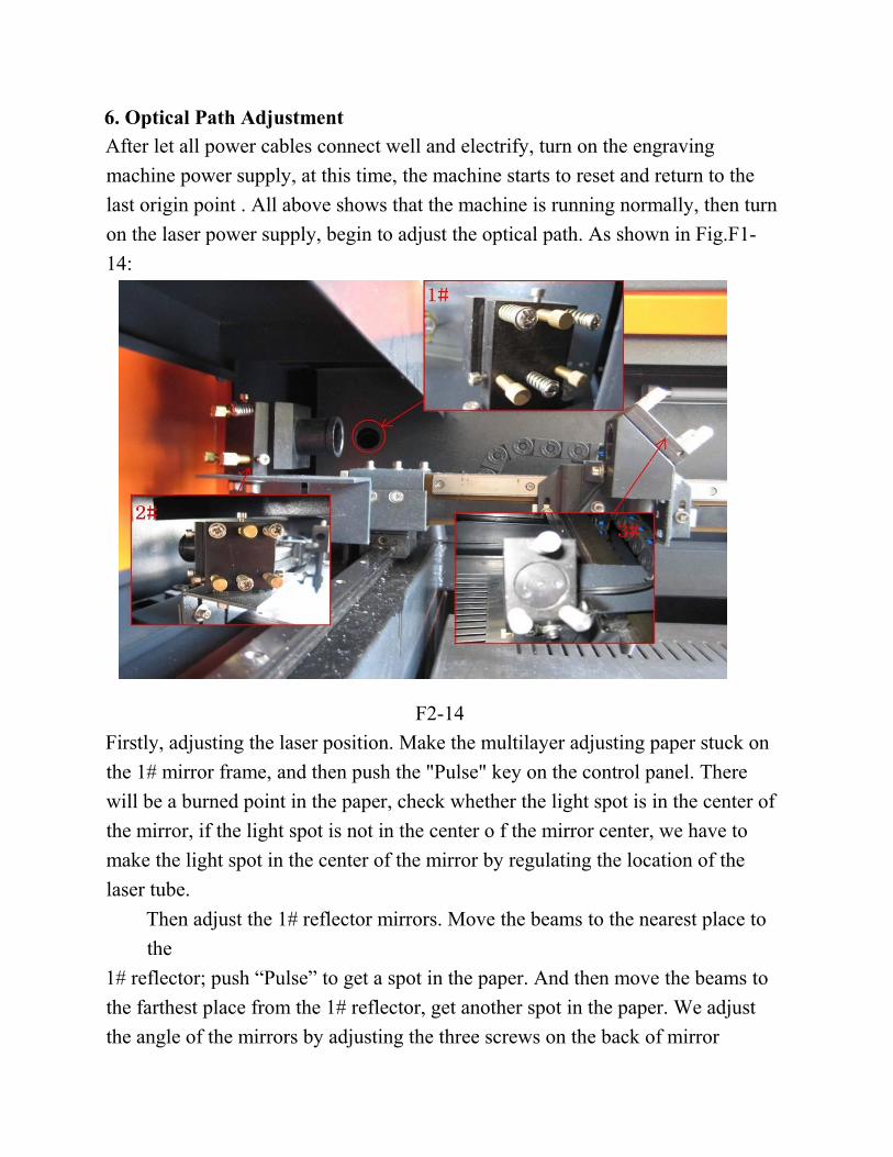
6. Optical Path Adjustment
After let all power cables connect well and electrify, turn on the engraving
machine power supply, at this time, the machine starts to reset and return to the
last origin point . All above shows that the machine is running normally, then turn
on the laser power supply, begin to adjust the optical path. As shown in Fig.F1-
14:
F2-14
Firstly, adjusting the laser position. Make the multilayer adjusting paper stuck on
the 1# mirror frame, and then push the "Pulse" key on the control panel. There
will be a burned point in the paper, check whether the light spot is in the center of
the mirror, if the light spot is not in the center o f the mirror center, we have to
make the light spot in the center of the mirror by regulating the location of the
laser tube.
Then adjust the 1# reflector mirrors. Move the beams to the nearest place to
the
1# reflector; push “Pulse” to get a spot in the paper. And then move the beams to
the farthest place from the 1# reflector, get another spot in the paper. We adjust
the angle of the mirrors by adjusting the three screws on the back of mirror
(clockwise rotation the above screw, the spot will be down; clockwise rotation of
the lower left corner of the screw, the spot will move to right; clockwise rotation
of the lower right corner of screw, the spot will move to left.), to insure that all
the spot are in the same place in the paper when and where the beam we move.
After adjust the 1# reflector mirror well, the next, adjust the mirror 2# as we
do at the first step, move the laser head to the nearest side to 2# reflector , then
make a spot in the paper , then move the laser head to the farthest place to 2# ,
make a spot. We have to adjust the further spot overlap with the first spot by
adjust the screws on the 2# reflector frame.
Note: As the best, the location of light spot should be in the center of mirrors. The light spot can not hit the edges of the mirrors. If playing in the edges, please continue to adjust the mirrors until the light spot in the central of them.
At last we have to check whether the light spots are superposition wherever
the laser head is. If the spots can not coincide, please re-adjust the optical path by
the way we talked above until the spots coincide
After finished the adjustment, we will check whether this laser spot is
playing in central of the laser head light hole. If not, turn off the laser power
supply, adjust the laser tube position. If it is left and right excursion, which side is
biased on, we move the laser tube to this side direction. Such as: if left, we adjust
the laser tube to left ; if right , we adjust the laser tube to right .
If the migration is up and down, we have to adjust the laser tube to the
opposite direction, that is, if up, we will make the laser tube down; if down, we
will make the laser tube up.
Note: The above adjustments is just for a low-voltage side of laser tube (light side), if we want to adjust high-voltage side of the laser to achieve the same effect, then the adjusting direction is opposite.
The detailed description of how to adjust optical path, please see Chapter 4
"Alignment Standards of Optical Path".
After adjustment of optical path, please close the laser tube protective cover.
Operation of laser machine Besides use the computer to control the function key, we can use the
Control Panel. The following is the brief instruction of control panel and main
function. There are 16 function keys and one LCD Panel in the Control Panel:
I.3.1 Introduction of Main Interface
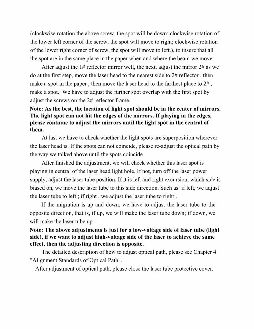
Idle Interface (display system time: day/month /year)
File:XX File Number:XXXX
Max Power:XX.X%
Run Speed:XXX mm/s
System Idle: 25/12/2010
Figure: 3.1-1
Running Interface (display run time of the selected file: hour/minute/second)
File:XX File Number :XXXX
Max Power:XX.X%
Run Speed:XXX mm/s
System Run: 00.12.40
Figure: 3.1-2
Main Interface (Pause)
File:XX File Number:XXXX
Max Power:XX.X%
Run Speed:XXX mm/s
System Paused: 00.12.40
Figure: 3.1-3
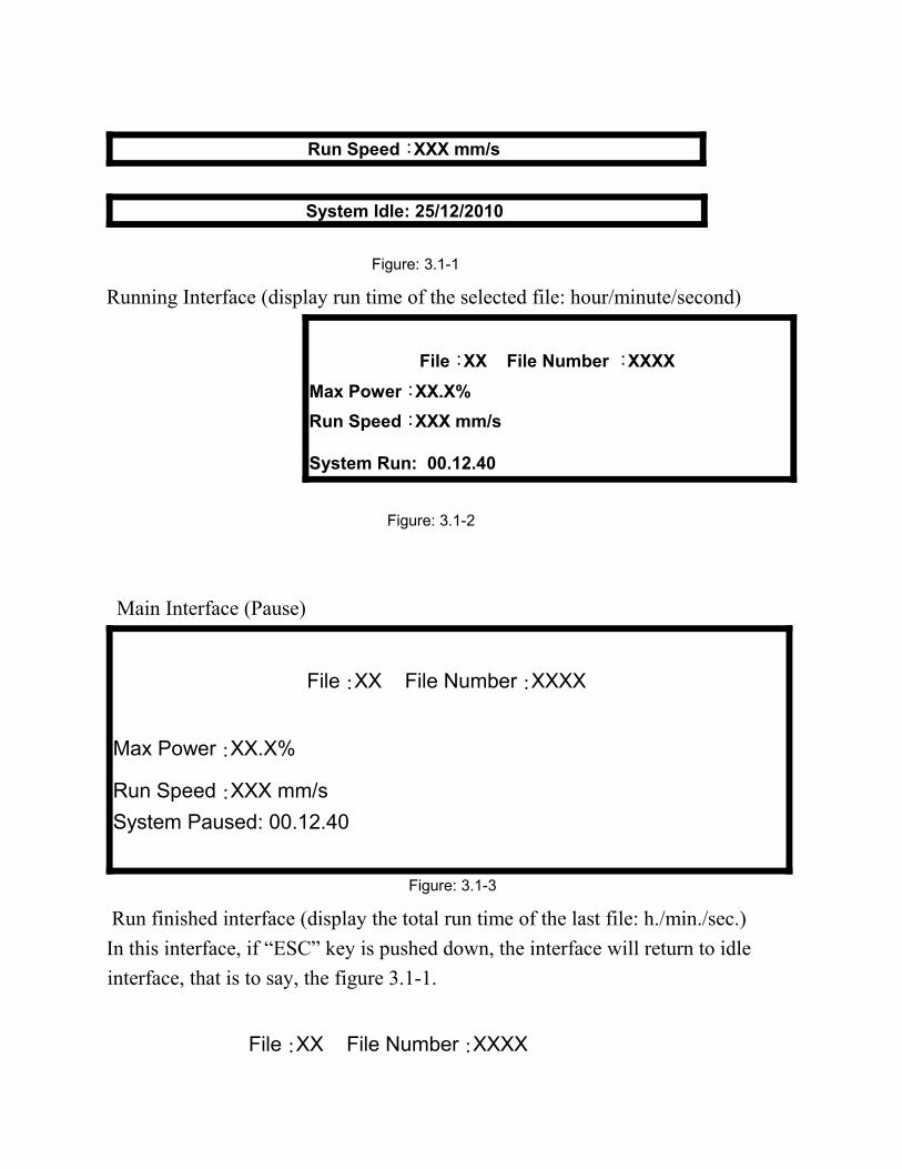
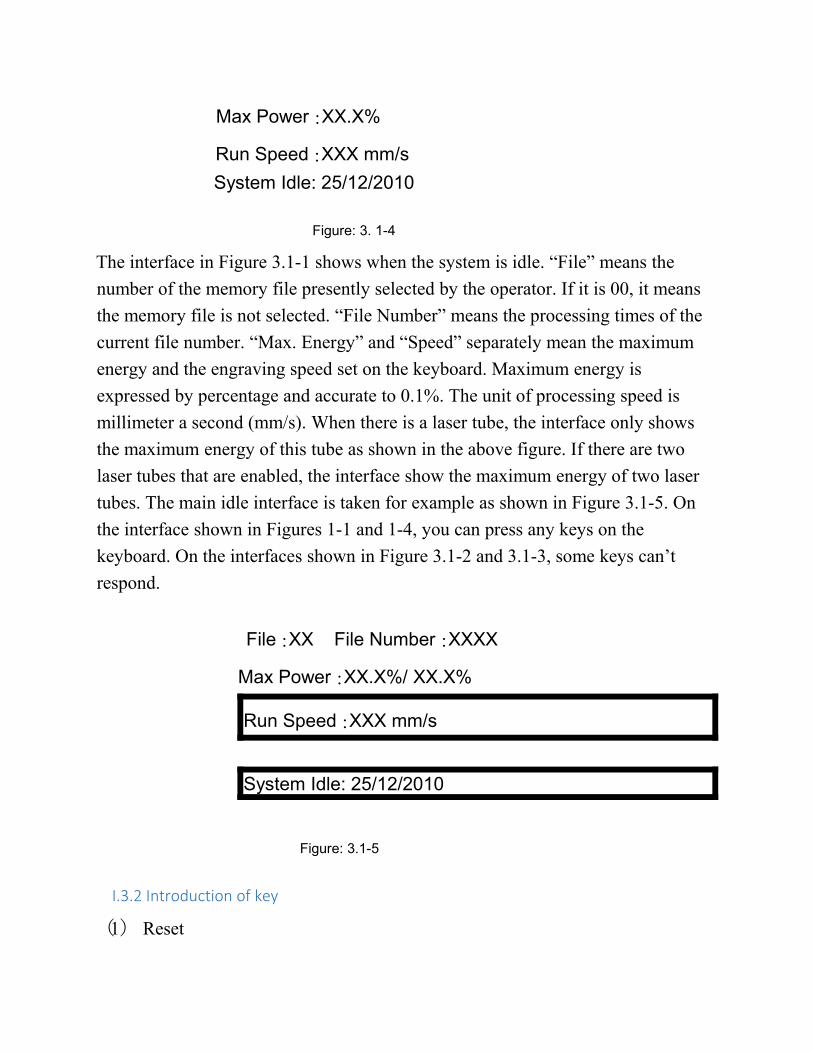
Run finished interface (display the total run time of the last file: h./min./sec.)
In this interface, if “ESC” key is pushed down, the interface will return to idle
interface, that is to say, the figure 3.1-1.
File:XX File Number:XXXX
Max Power:XX.X%
Run Speed:XXX mm/s
System Idle: 25/12/2010
Figure: 3. 1-4
The interface in Figure 3.1-1 shows when the system is idle. “File” means the
number of the memory file presently selected by the operator. If it is 00, it means
the memory file is not selected. “File Number” means the processing times of the
current file number. “Max. Energy” and “Speed” separately mean the maximum
energy and the engraving speed set on the keyboard. Maximum energy is
expressed by percentage and accurate to 0.1%. The unit of processing speed is
millimeter a second (mm/s). When there is a laser tube, the interface only shows
the maximum energy of this tube as shown in the above figure. If there are two
laser tubes that are enabled, the interface show the maximum energy of two laser
tubes. The main idle interface is taken for example as shown in Figure 3.1-5. On
the interface shown in Figures 1-1 and 1-4, you can press any keys on the
keyboard. On the interfaces shown in Figure 3.1-2 and 3.1-3, some keys can’t
respond.
File:XX File Number:XXXX
Max Power:XX.X%/ XX.X%
Run Speed:XXX mm/s
System Idle: 25/12/2010
Figure: 3.1-5
I.3.2 Introduction of key
(1) Reset
On any interfaces, press the Reset key (or when the system is powered) and
the mainboard will be reset. The machine will seek for the origin (configured
according to the user’s parameters through start-up and reset) and show the
“Reset-in-progress” prompted in the interface. The machine having successfully
returned to the origin, the laser head will automatically move to the setpoint set
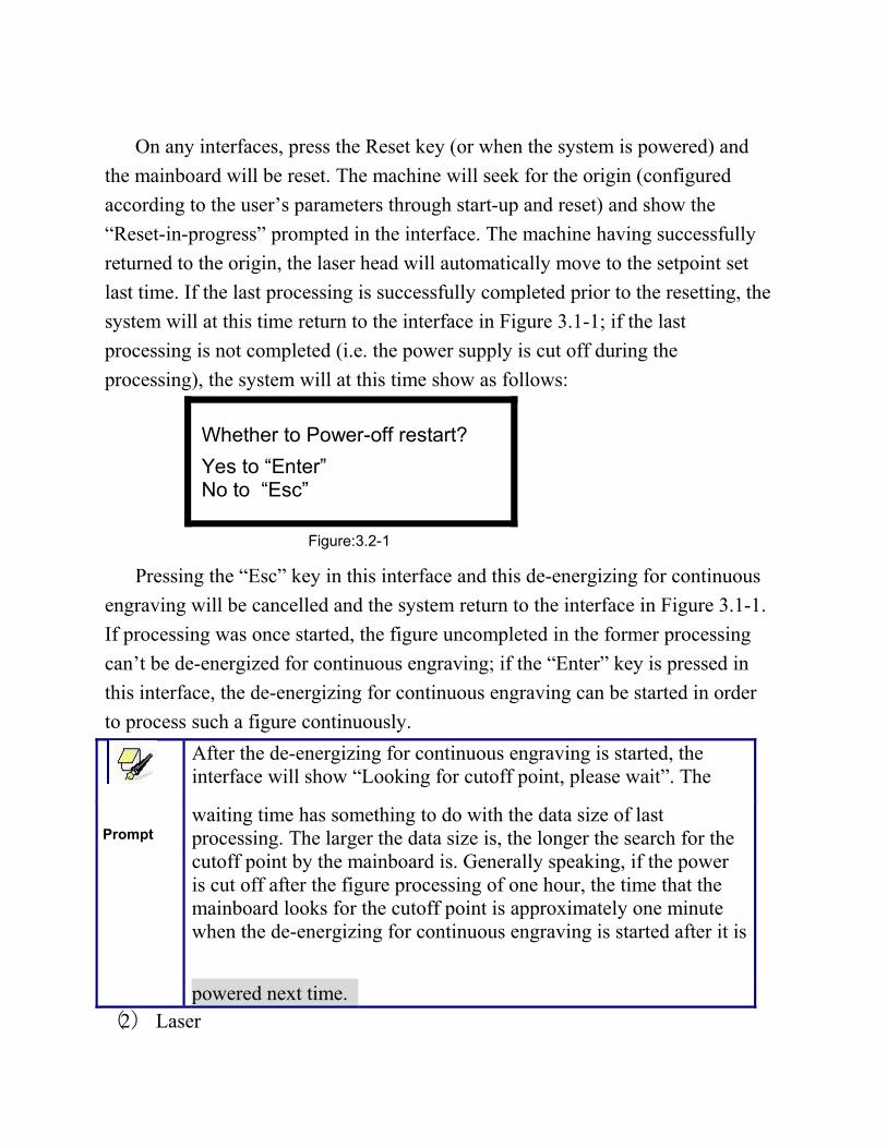
last time. If the last processing is successfully completed prior to the resetting, the
system will at this time return to the interface in Figure 3.1-1; if the last
processing is not completed (i.e. the power supply is cut off during the
processing), the system will at this time show as follows:
Whether to Power-off restart?
Yes to “Enter” No to “Esc”
Figure:3.2-1
Pressing the “Esc” key in this interface and this de-energizing for continuous
engraving will be cancelled and the system return to the interface in Figure 3.1-1.
If processing was once started, the figure uncompleted in the former processing
can’t be de-energized for continuous engraving; if the “Enter” key is pressed in
this interface, the de-energizing for continuous engraving can be started in order
to process such a figure continuously.
After the de-energizing for continuous engraving is started, the interface will show “Looking for cutoff point, please wait”. The
Prompt
waiting time has something to do with the data size of last processing. The larger the data size is, the longer the search for the cutoff point by the mainboard is. Generally speaking, if the power is cut off after the figure processing of one hour, the time that the mainboard looks for the cutoff point is approximately one minute when the de-energizing for continuous engraving is started after it is
powered next time. (2) Laser
Laser
On the system idle interface, the work finished interface, the system paused
interface and the interface to prompt whether to de-energize for continuous
engraving, press the “Laser” key and the laser outputs on the bursting. The time
of open laser may be set. If the time is set to zero, then the outputting time is the
time when the “Laser” key is pressed, that is to say, press this key for outputting
and release it for blanking. If the time is not zero, such as, 100ms, then the laser
flash 100ms when you push down
the laser key. You can press the “Down” key on pressing the “Laser” key to start
manual cutting. The laser energy of burst is the maximum energy value set on the
keyboard. It is no use to press the “Laser” key on other interfaces. If the water
protector is started and something wrong happens to the protector, no laser will be
outputted after the laser and the interface prompts dislocation.
(3)Max. Power key
Max
Power
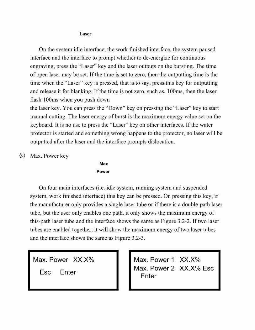
On four main interfaces (i.e. idle system, running system and suspended
system, work finished interface) this key can be pressed. On pressing this key, if
the manufacturer only provides a single laser tube or if there is a double-path laser
tube, but the user only enables one path, it only shows the maximum energy of
this-path laser tube and the interface shows the same as Figure 3.2-2. If two laser
tubes are enabled together, it will show the maximum energy of two laser tubes
and the interface shows the same as Figure 3.2-3.
Max. Power XX.X%
Esc Enter
Max. Power 1 XX.X% Max. Power 2 XX.X% Esc
Enter
Figure: 3.2-2 Figure:3.2-2
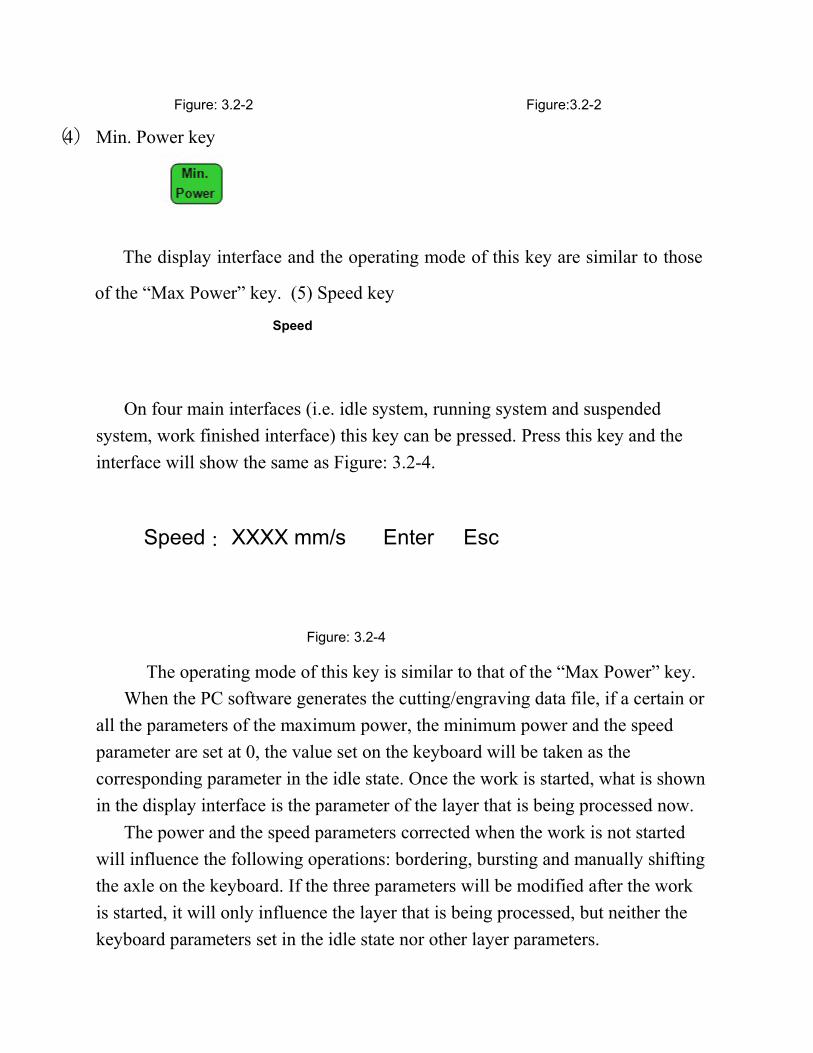
(4)Min. Power key
The display interface and the operating mode of this key are similar to those
of the “Max Power” key. (5) Speed key
Speed
On four main interfaces (i.e. idle system, running system and suspended
system, work finished interface) this key can be pressed. Press this key and the
interface will show the same as Figure: 3.2-4.
Speed: XXXX mm/s Enter Esc
Figure: 3.2-4
The operating mode of this key is similar to that of the “Max Power” key.
When the PC software generates the cutting/engraving data file, if a certain or
all the parameters of the maximum power, the minimum power and the speed
parameter are set at 0, the value set on the keyboard will be taken as the
corresponding parameter in the idle state. Once the work is started, what is shown
in the display interface is the parameter of the layer that is being processed now.
The power and the speed parameters corrected when the work is not started
will influence the following operations: bordering, bursting and manually shifting
the axle on the keyboard. If the three parameters will be modified after the work
is started, it will only influence the layer that is being processed, but neither the
keyboard parameters set in the idle state nor other layer parameters.
Online parameter correction of the layer that is being processedcan greatly facilitate the user’s searching for a reasonable laser power and speed matching value.
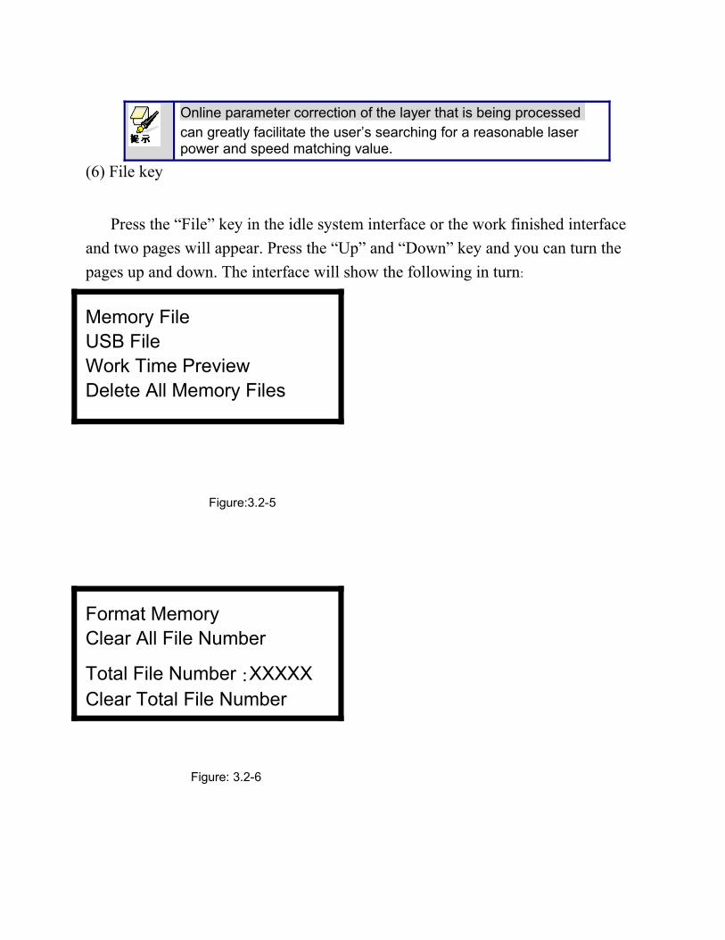
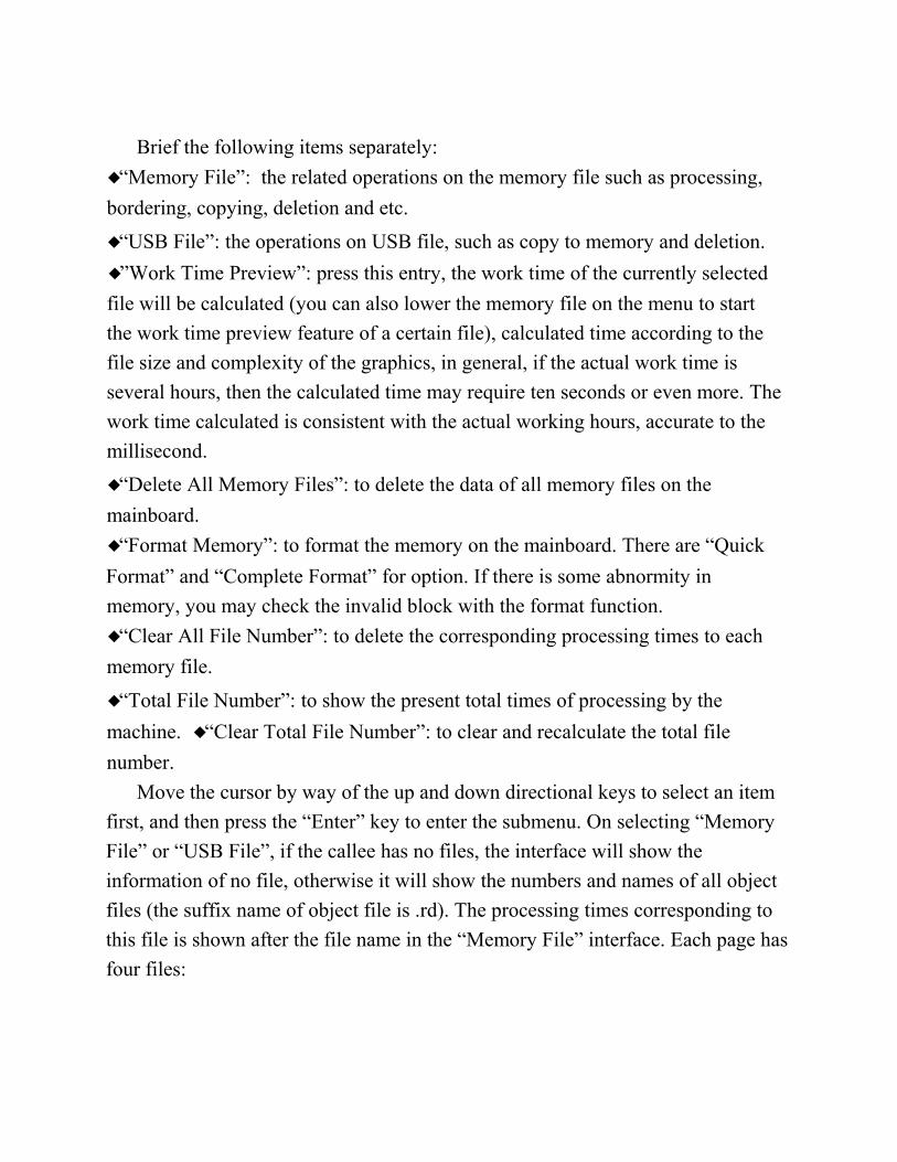
(6) File key
Press the “File” key in the idle system interface or the work finished interface
and two pages will appear. Press the “Up” and “Down” key and you can turn the
pages up and down. The interface will show the following in turn:
Memory File USB File Work Time Preview Delete All Memory Files
Figure:3.2-5
Format Memory Clear All File Number
Total File Number:XXXXX Clear Total File Number
Figure: 3.2-6
Brief the following items separately:
◆“Memory File”: the related operations on the memory file such as processing,
bordering, copying, deletion and etc.
◆“USB File”: the operations on USB file, such as copy to memory and deletion.
◆”Work Time Preview”: press this entry, the work time of the currently selected
file will be calculated (you can also lower the memory file on the menu to start
the work time preview feature of a certain file), calculated time according to the
file size and complexity of the graphics, in general, if the actual work time is
several hours, then the calculated time may require ten seconds or even more. The
work time calculated is consistent with the actual working hours, accurate to the
millisecond.
◆“Delete All Memory Files”: to delete the data of all memory files on the
mainboard.
◆“Format Memory”: to format the memory on the mainboard. There are “Quick
Format” and “Complete Format” for option. If there is some abnormity in
memory, you may check the invalid block with the format function.
◆“Clear All File Number”: to delete the corresponding processing times to each
memory file.
◆“Total File Number”: to show the present total times of processing by the
machine. ◆“Clear Total File Number”: to clear and recalculate the total file
number.
Move the cursor by way of the up and down directional keys to select an item
first, and then press the “Enter” key to enter the submenu. On selecting “Memory
File” or “USB File”, if the callee has no files, the interface will show the
information of no file, otherwise it will show the numbers and names of all object
files (the suffix name of object file is .rd). The processing times corresponding to
this file is shown after the file name in the “Memory File” interface. Each page has
four files:
Select a certain file by pressing the directional keys (move the cursor with the
up and down keys and turn pages with the left and right keys) first, and then press
the “Enter” key to enter the submenu. For memory file, it supports such six items
as
“Copy to USB”, “Run”, “Deletion”, “Work Time Preview”, “Track Frame” and
“Clear File Number”.
On pressing the “Enter” key when you select the “Run” item, directly start the
processing of this file and the interface shows the same as Figure 8.1-3 (Running
Interface); selecting “To USB” and pressing the “Enter” key, this memory file
will be copied to USB disk. If copying fails, the interface will show the error
information; if copying succeeds, the system will return to the prior interface after
the bell rings. On selecting the “Deletion” and pressing the “Enter” key, this file
in the memory will be deleted. Selecting the “Work Time Preview” and pressing
the “Enter” key, to start the work time preview feature of the certain file. If
“Track Frame” is selected, the frame of the graph is previewed. Then if “Clear
File Number” is selected, the work number of the certain file is set to zero.
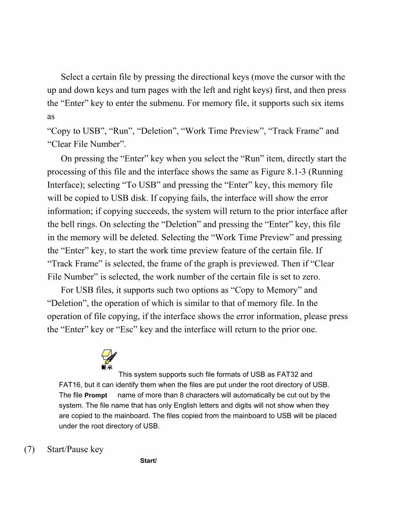
For USB files, it supports such two options as “Copy to Memory” and
“Deletion”, the operation of which is similar to that of memory file. In the
operation of file copying, if the interface shows the error information, please press
the “Enter” key or “Esc” key and the interface will return to the prior one.
This system supports such file formats of USB as FAT32 and
FAT16, but it can identify them when the files are put under the root directory of USB.
The file Prompt name of more than 8 characters will automatically be cut out by the
system. The file name that has only English letters and digits will not show when they
are copied to the mainboard. The files copied from the mainboard to USB will be placed
under the root directory of USB.
(7) Start/Pause key Start/
Pause
Under the four main interfaces it is ok to press the Start/Pause key. Press this
key on the system idle interface or work finished interface; the selected file will
be processed. Press this key under the running system interface, and the work will
be suspended. Press this key under the suspended system interface, and the
suspended work will continue.
(8) Origin key
It will respond when this key is pressed under the idle system interface or the
work finished interface. If the single setpoint logic is selected by the system, press
this key and the mainboard will take the current X/Y-axle position of the machine
as the relative origin of the figure; if the multiple setpoint logic is selected by the
system, it is invalid to press this key at any time.
(9) Frame key
It is valid to press this key under the idle system interface and the work
finished interface. Press this key and the bordering will be operated on the
currently selected file.
(10) Esc and Enter key
Press the Esc or Enter key under different interfaces means to confirm or deny
this operation.
(11) Directional Keys (Up, Down, Left and Right keys)
In addition to being used for modifying parameters and moving the cursor as
abovementioned, the directional keys can be used to move the kinematic axis
under such three interfaces as idle, suspended system or work finished interface.
Under such three interfaces, press the Left and Right keys to move X axis and
press the Up and down keys to move Y axis. If the inching distance is set at 0, the
moving time means the time of pressing this key, which means that movement
starts after the one of the keys is pressed and movement stops after the keys are
released. Where the inching distance is not 0, the corresponding axis will move
for the corresponding inching distance after one of the directional keys is pressed
once. In the movement processing the speed can be increased or reduced
automatically in order to reach the maximum/minimum coordinates. The
maximum speed of key movement is the speed value set on the keyboard when
the system lies idle.
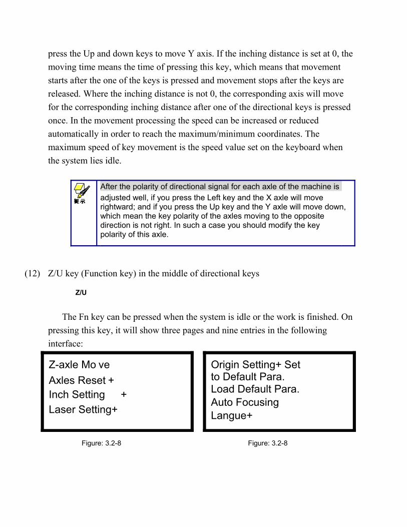
After the polarity of directional signal for each axle of the machine isadjusted well, if you press the Left key and the X axle will move rightward; and if you press the Up key and the Y axle will move down,which mean the key polarity of the axles moving to the opposite direction is not right. In such a case you should modify the key polarity of this axle.
(12) Z/U key (Function key) in the middle of directional keys
Z/U
The Fn key can be pressed when the system is idle or the work is finished. On
pressing this key, it will show three pages and nine entries in the following
interface:
Z-axle Mo ve
Axles Reset + Inch Setting +
Laser Setting+
Origin Setting+ Set to Default Para. Load Default Para. Auto Focusing Langue+
Figure: 3.2-8 Figure: 3.2-8
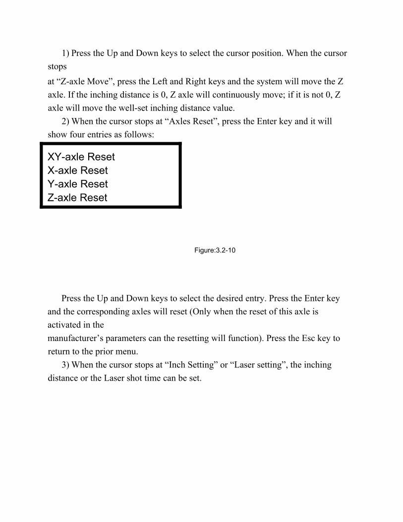
1) Press the Up and Down keys to select the cursor position. When the cursor
stops
at “Z-axle Move”, press the Left and Right keys and the system will move the Z
axle. If the inching distance is 0, Z axle will continuously move; if it is not 0, Z
axle will move the well-set inching distance value.
2) When the cursor stops at “Axles Reset”, press the Enter key and it will
Press the Up and Down keys to select the desired entry. Press the Enter key
and the corresponding axles will reset (Only when the reset of this axle is
activated in the
manufacturer’s parameters can the resetting will function). Press the Esc key to
return to the prior menu.
3) When the cursor stops at “Inch Setting” or “Laser setting”, the inching
distance or the Laser shot time can be set.
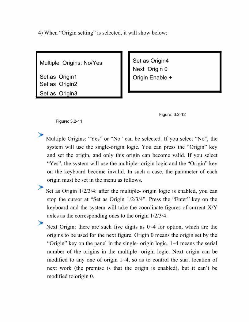
4) When “Origin setting” is selected, it will show below:
Multiple Origins: No/Yes
Set as Origin1 Set as Origin2
Set as Origin3
Set as Origin4
Next Origin 0
Origin Enable +
Figure: 3.2-12
Figure: 3.2-11
Multiple Origins: “Yes” or “No” can be selected. If you select “No”, the
system will use the single-origin logic. You can press the “Origin” key
and set the origin, and only this origin can become valid. If you select
“Yes”, the system will use the multiple- origin logic and the “Origin” key
on the keyboard become invalid. In such a case, the parameter of each
origin must be set in the menu as follows.
Set as Origin 1/2/3/4: after the multiple- origin logic is enabled, you can
stop the cursor at “Set as Origin 1/2/3/4”. Press the “Enter” key on the
keyboard and the system will take the coordinate figures of current X/Y
axles as the corresponding ones to the origin 1/2/3/4.
Next Origin: there are such five digits as 0~4 for option, which are the
origins to be used for the next figure. Origin 0 means the origin set by the
“Origin” key on the panel in the single- origin logic. 1~4 means the serial
number of the origins in the multiple- origin logic. Next origin can be
modified to any one of origin 1~4, so as to control the start location of
next work (the premise is that the origin is enabled), but it can’t be
modified to origin 0.
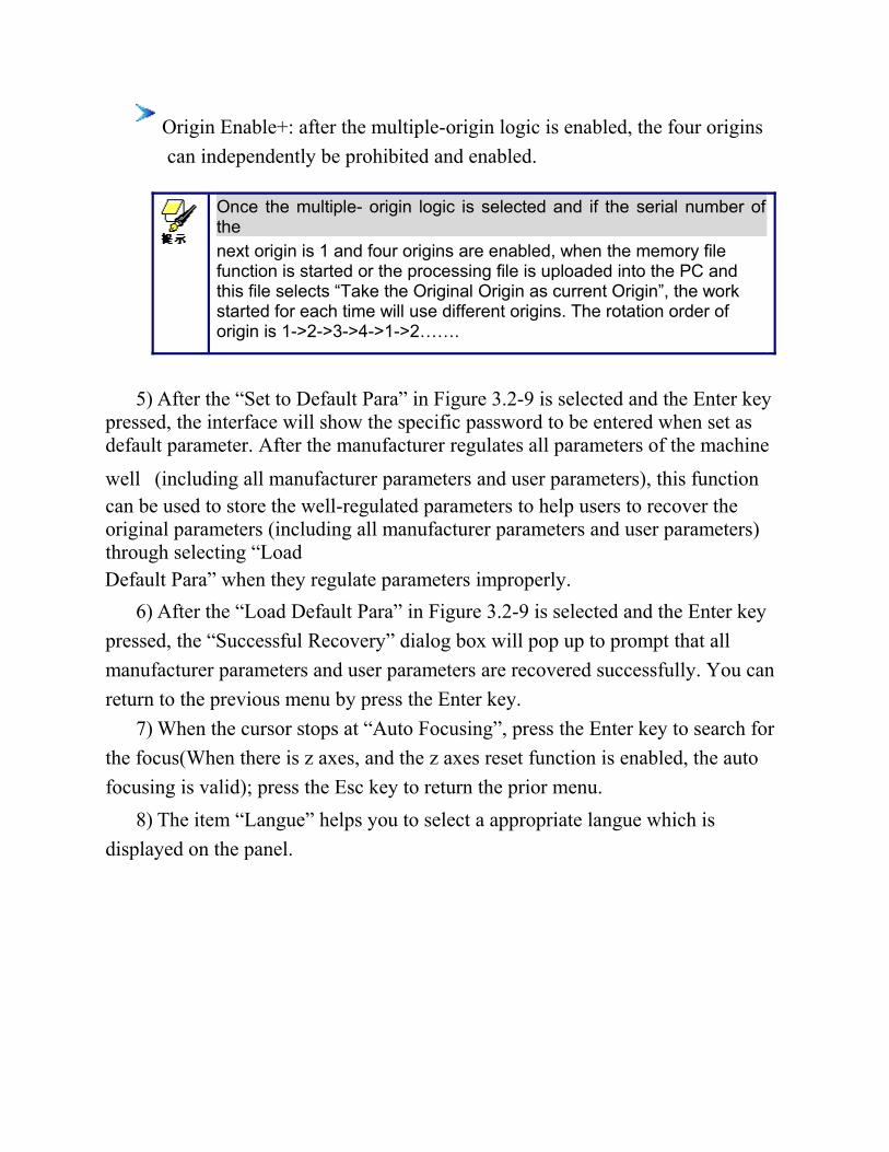
Origin Enable+: after the multiple-origin logic is enabled, the four origins
can independently be prohibited and enabled.
Once the multiple- origin logic is selected and if the serial number ofthe
next origin is 1 and four origins are enabled, when the memory file function is started or the processing file is uploaded into the PC and this file selects “Take the Original Origin as current Origin”, the work started for each time will use different origins. The rotation order of origin is 1->2->3->4->1->2…….
5) After the “Set to Default Para” in Figure 3.2-9 is selected and the Enter keypressed, the interface will show the specific password to be entered when set as default parameter. After the manufacturer regulates all parameters of the machine
well (including all manufacturer parameters and user parameters), this function can be used to store the well-regulated parameters to help users to recover the original parameters (including all manufacturer parameters and user parameters) through selecting “Load Default Para” when they regulate parameters improperly.
6) After the “Load Default Para” in Figure 3.2-9 is selected and the Enter key
pressed, the “Successful Recovery” dialog box will pop up to prompt that all
manufacturer parameters and user parameters are recovered successfully. You can
return to the previous menu by press the Enter key.
7) When the cursor stops at “Auto Focusing”, press the Enter key to search for
the focus(When there is z axes, and the z axes reset function is enabled, the auto
focusing is valid); press the Esc key to return the prior menu.
8) The item “Langue” helps you to select a appropriate langue which is
displayed on the panel.
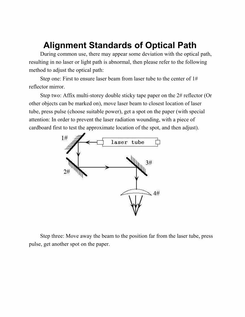
Alignment Standards of Optical Path During common use, there may appear some deviation with the optical path,
resulting in no laser or light path is abnormal, then please refer to the following
method to adjust the optical path:
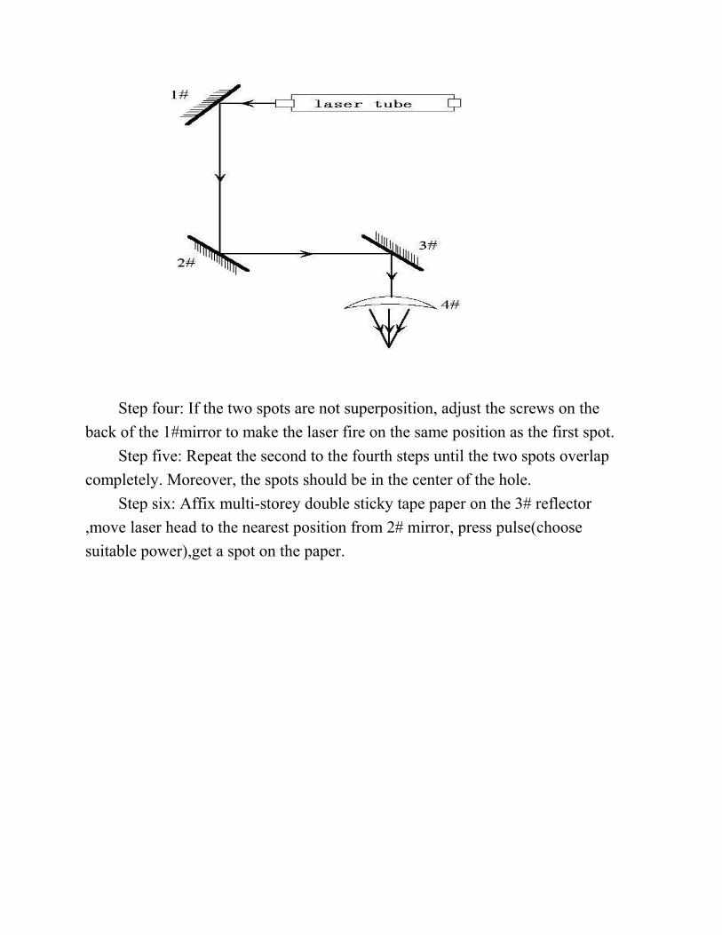
Step one: First to ensure laser beam from laser tube to the center of 1#
reflector mirror.
Step two: Affix multi-storey double sticky tape paper on the 2# reflector (Or
other objects can be marked on), move laser beam to closest location of laser
tube, press pulse (choose suitable power), get a spot on the paper (with special
attention: In order to prevent the laser radiation wounding, with a piece of
cardboard first to test the approximate location of the spot, and then adjust).
Step three: Move away the beam to the position far from the laser tube, press
pulse, get another spot on the paper.
Step four: If the two spots are not superposition, adjust the screws on the
back of the 1#mirror to make the laser fire on the same position as the first spot.
Step five: Repeat the second to the fourth steps until the two spots overlap
completely. Moreover, the spots should be in the center of the hole.
Step six: Affix multi-storey double sticky tape paper on the 3# reflector
,move laser head to the nearest position from 2# mirror, press pulse(choose
suitable power),get a spot on the paper.
Step seven: Move away the laser head to the position farthest from the 2#
mirror, press pulse(first to detect the approximate location of laser with a piece of
cardboard to prevent wounding),get another spot .
Step eight: If the two spots are not superposition, adjust the screws on the
back of the 2# mirror to make the laser fire on the same position as the first spot.
Step nine: Repeat the sixth to eighth steps until the two spots overlap
completely.
Moreover, the spots should be in the center of the hole.
Step ten: Affix multi-storey double sticky tape paper on the 3# reflector,
press pulse, get a spot on the paper. If it is in the center of light hole, then pass.
Step XI: If the laser light is not in the center of light hole, as below figure:
In the left Figure, the spot is upper and right biased.
Top to bottom bias: can only raise or lower the laser tube.
Inside and outside bias: only move the laser tube in or out to adjust.
In this case, it is essential to lower the laser tube (here refers to low-voltage
side of the laser tube), and then, from the beginning of all the re-adjustment of
the first step.
Note: The operator can’t do the above working until after the professional training. Otherwise, the operator do this working must with the help of the professional .The operator must pay attention to security when adjusting, to prevent the laser radiation wounding.
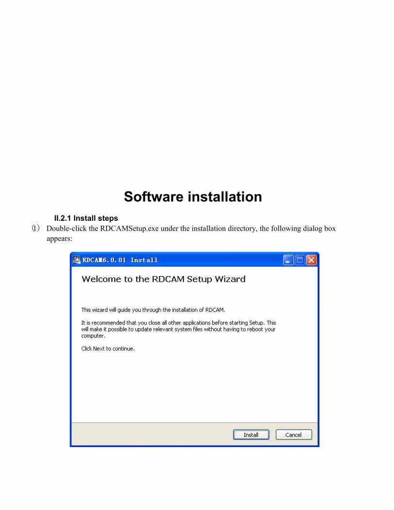
Software installation II.2.1 Install steps
(1) Double-click the RDCAMSetup.exe under the installation directory, the following dialog box appears:
(2) Click【Install ,】 when extract copy is to be completed, the installation main interface appears:
II.2.2 Installation settings The installer can choose different installation content.
1> Install/Uninstall USB driver , reference《Install USB driver》
2> According to the different customer application needs and the habit of using to select the type of software
a. Stand-alone software LaserWork.
b. The software that plug-ins to CorelDraw. Support the version from Coreldraw11 to X5.
c. The software that plug-ins to AutoCad. Support the version from 2004 to 2010.
d. The software that plug-ins to Cadian.
e. The software that plug-ins to Illustrator.
3> Choose a different installation languages
At present, it support Simplified Chinese, Traditional Chinese, English and the custom language type.
4> Select the software matches the motherboard
The software can support three kind of
motherboards:RDLC430、RDLC320、RDC633X. Both RDLC320 and RDC633X are
compatible, but RDLC430 is different. So, please choose the corresponding software with motherboard. Otherwise, it does not work. 5> Locate install path
When install the LaserWork, default install path is “C:\”, for change the install path, check this option.
When install the plug software RDPlug, under normal circumstances, the install programwill locate to the target software automatically. If the installer does not locate to the target software automatically, you need to check this option, and locate to the target software manually.
6> Pen drawing lines
This option is only applicable to a particular machine, which has the function of the chalk line, ordinary machines do not need to check this.
7> Plug laserwork
The installer default install a special plug-ins RDPlug, if the users are more accustomed to using LaserWork program ,can check this.
8> Demo version installation
According to the type of software installation, the installation language, the
choice of motherboard generate different versions of the DEMO Software. II.2.3Installation
Choose the type of software, installation language and the appropriate motherboard.
Click【Install 】 to install the software. After installation is complete, the following dialog box
appears to prompt the user that the software has been installed successfully.
II.2.4 Exit
After installing the installation needed. Click【Exit】to end the installation process.
Because of the possible need to use several installation, so the installation dialog does
not automatically exit, until users click button【Exit】.
II.2.4 Other matters 1> Before installing the plug-in software, the software that has been articulated should be shut down.
After installation, restart the software.
2> The regular version and the DEMO version of the plug-in software is covered by eachother. 3> In the default installation path, the normal version and the DEMO version of the independent software and different types of independent software motherboard with each other.
For the same time to install two versions, select the【Locate install path】.The regular
version and the Demo version should be installed in the different location.
In addition, need to the appropriate software installation location, manually add a desktop shortcut for the software.
4> Modify the information of manufacturers
In the package, in addition to RDCAMSetup, there are four text files.
Info_Sche、Info_Tche、Info_En、Info_Other, the four files correspond to the software
information of manufacturers that be displayed in Simplified Chinese, Traditional Chinese, English and the custom language. If the four text is modified, manufacturer information also will be installed when the program was installed.
Open the text that should be modify, an example in Simplified Chinese:
1 = Company Name:
2 = ... (Fill in company name here)
And so on, the company information in other languages is the same set.
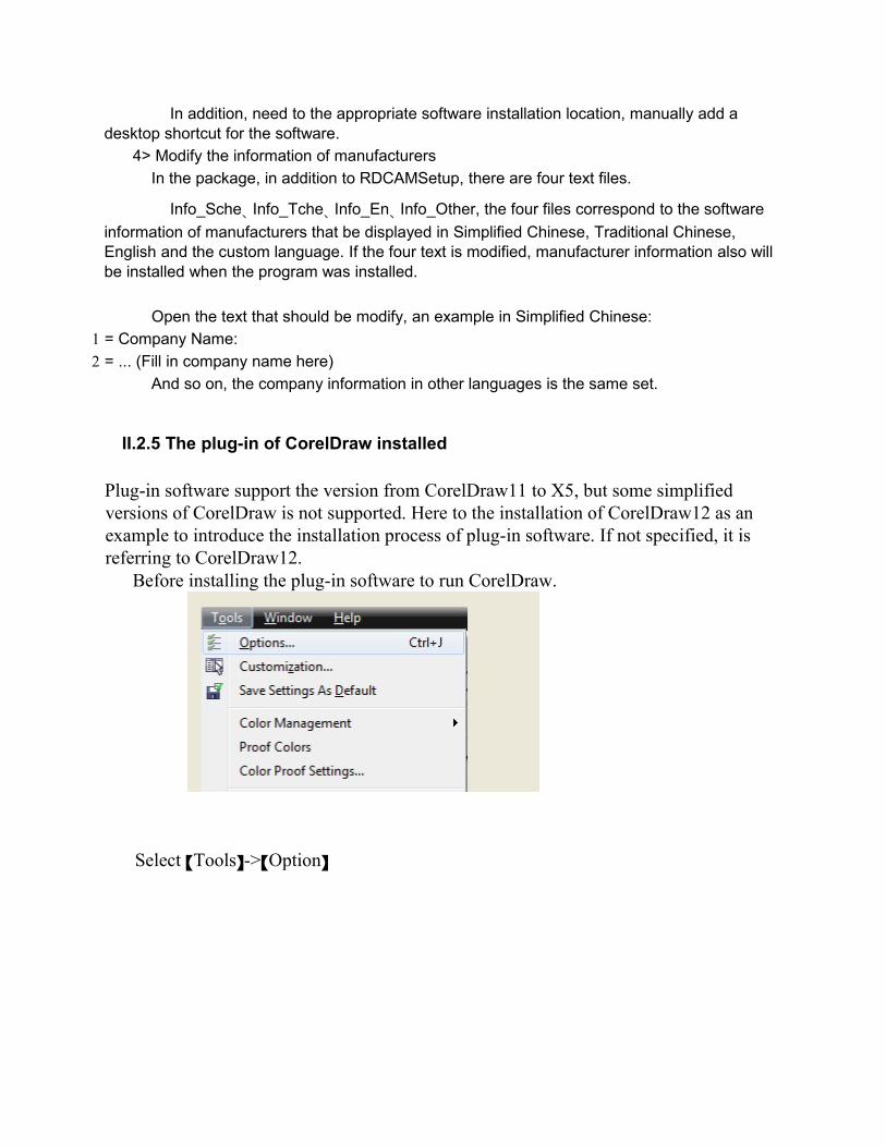
II.2.5 The plug-in of CorelDraw installed
Plug-in software support the version from CorelDraw11 to X5, but some simplified versions of CorelDraw is not supported. Here to the installation of CorelDraw12 as an example to introduce the installation process of plug-in software. If not specified, it is referring to CorelDraw12. Before installing the plug-in software to run CorelDraw.
Select 【Tools】->【Option】
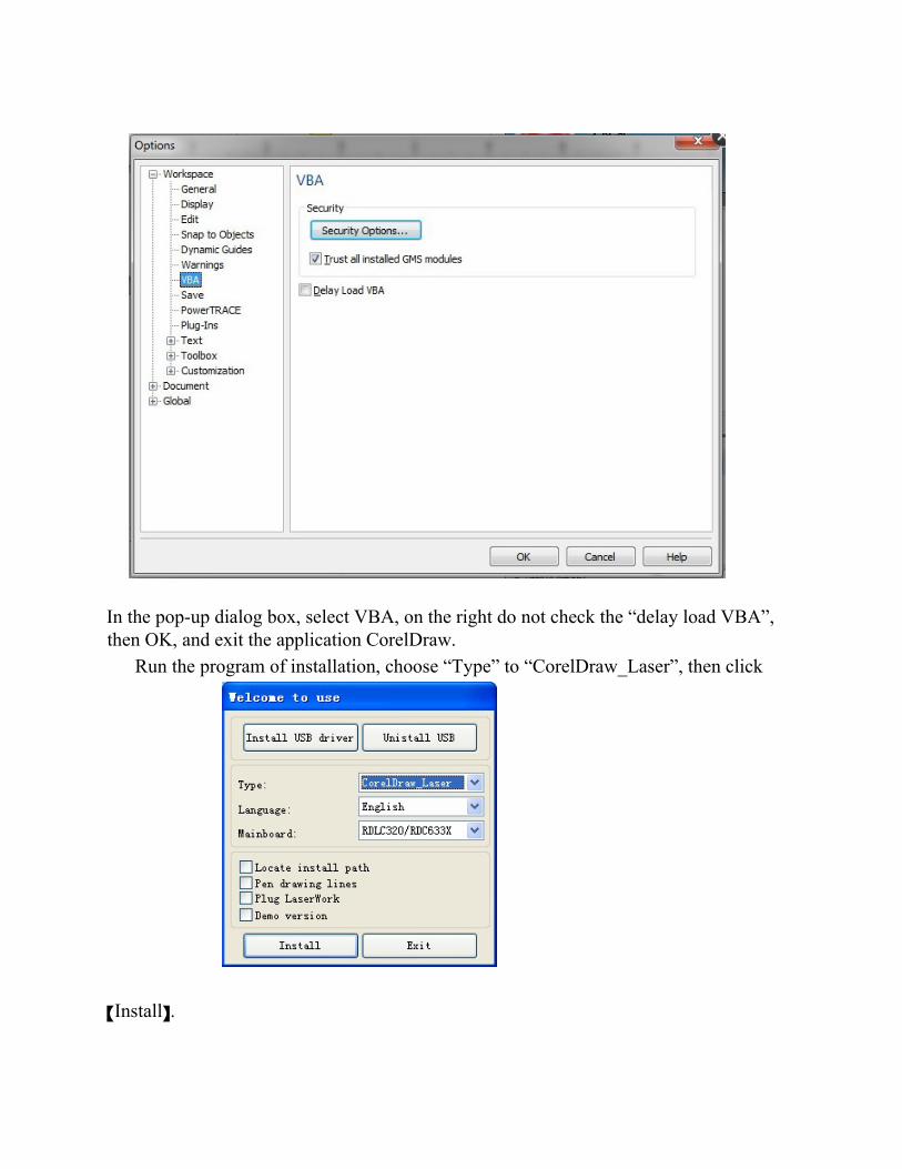
In the pop-up dialog box, select VBA, on the right do not check the “delay load VBA”, then OK, and exit the application CorelDraw.
Run the program of installation, choose “Type” to “CorelDraw_Laser”, then click
【Install】.
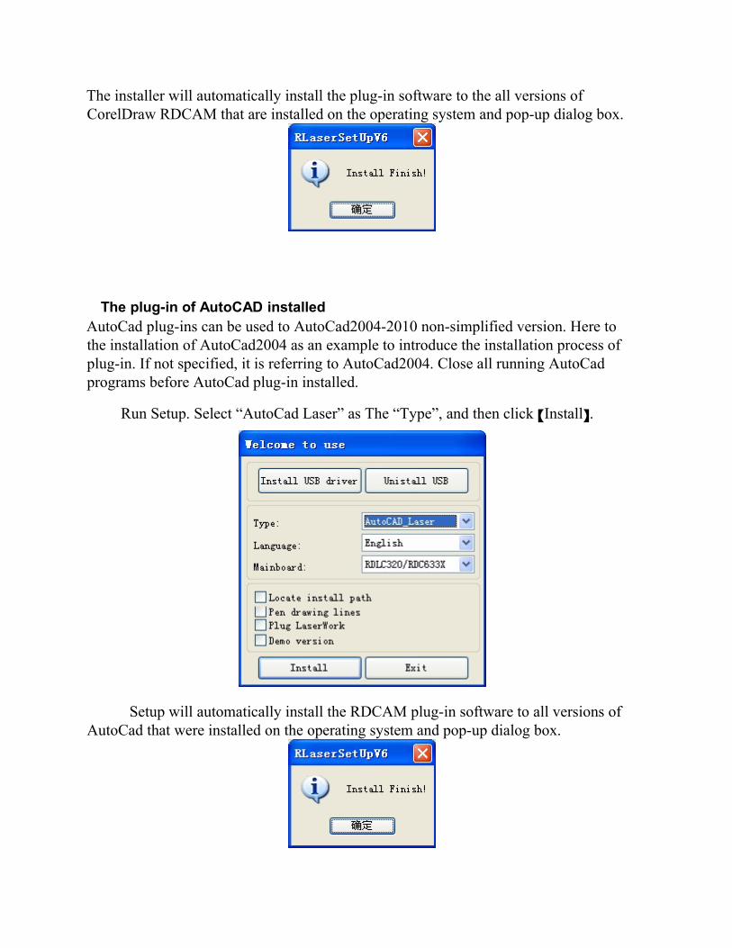
The installer will automatically install the plug-in software to the all versions of CorelDraw RDCAM that are installed on the operating system and pop-up dialog box.
The plug-in of AutoCAD installed AutoCad plug-ins can be used to AutoCad2004-2010 non-simplified version. Here to the installation of AutoCad2004 as an example to introduce the installation process of plug-in. If not specified, it is referring to AutoCad2004. Close all running AutoCad programs before AutoCad plug-in installed.
Run Setup. Select “AutoCad Laser” as The “Type”, and then click 【Install】.
Setup will automatically install the RDCAM plug-in software to all versions of AutoCad that were installed on the operating system and pop-up dialog box.
.
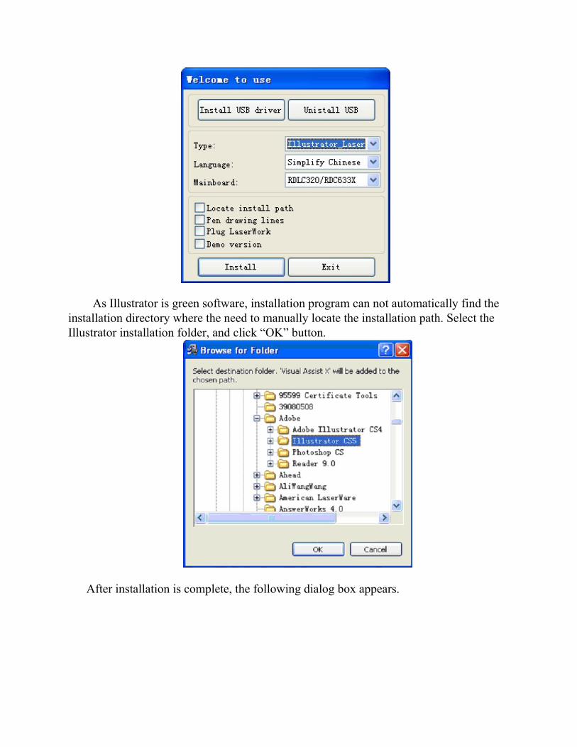
The plug-in of IIIustrator installed Illustrator plug-in are now available for the non-simplified of Illustrator CS5. The other version is not tested. When Illustrator was installed, you should close the running Illustrator procedures.
Run Setup. Select “Illustrator_Laser” as the “Type”. And then click 【Install】
.
As Illustrator is green software, installation program can not automatically find the installation directory where the need to manually locate the installation path. Select the Illustrator installation folder, and click “OK” button.
After installation is complete, the following dialog box appears.
Exit the installation program, and run Illustrator.