44
Installation and Configuration Horizon Cloud 1.3 with Pivot3 Hyperconverged Infrastructure August 2017
Installation and Configuration
Horizon Cloud 1.3 with Pivot3 Hyperconverged Infrastructure
August 2017
Installation and Configuration
VMware, Inc. 2
Copyright © 2016, 2017 VMware, Inc. All rights reserved. This product is protected by U.S. and international copyright and intellectual property laws. This product is covered by one or more patents listed at http://www.vmware.com/download/patents.html.
VMware is a registered trademark or trademark of VMware, Inc. in the United States and/or other jurisdictions. All other marks and names mentioned herein may be trademarks of their respective companies.
VMware, Inc. 3401 Hillview Ave Palo Alto, CA 94304 www.vmware.com
VMware, Inc. 3
Contents
About Horizon Cloud with On-Premises Infrastructure Installation and Configuration .......................................................................................... 4
Intended Audience ................................................................................................................. 4
VMware Technical Publications Glossary .............................................................................. 4
Contacting VMware Support ................................................................... 5
Contacting Pivot3 Support ...................................................................... 5
Overview of a Horizon Cloud with On-Premises Infrastructure Installation6
Networking Requirements ...................................................................................................... 6
Transparent Page Sharing ..................................................................................................... 7
Installing and Configuring Horizon Cloud with On-Premises Infrastructure on Pivot3 Hyperconverged Infrastructure ................................................ 8
Section 1 Install Pivot3 vSTAC Nodes .............................................................................. 8
Section 2 vSTAC Hard Drive & Network Ports .................................................................. 9
Section 3 Configure ESXi for VMware Access ................................................................ 12
Section 4 Create the VMware Datastore ......................................................................... 20
Deploying Horizon Air Link into a Pivot3 vPG Environment ................................................. 35
Pivot3 vSTAC Cluster Appendixes ........................................................ 42
Appendix A - Static IP Addresses and Host Names for Pivot3 vSTAC Cluster Setup ......... 42
Appendix B - Active Directory Details for Pivot3 vSTAC Cluster Setup ............................... 43
Installation and Configuration
4
About Horizon Cloud with On-Premises
Infrastructure Installation and
Configuration
This document describes the process of installing and configuring Horizon Cloud with On-Premises Infrastructure with Pivot3 vSTAC Hyperconverged Infrastructure (HCI). This information serves as an example of a basic cluster configured using Pivot3 HCI for use with Horizon Cloud with On-Premises Infrastructure
For information about how to use the product after you finish all the tasks outlined in this guide, see the Horizon Cloud with On-Premises Infrastructure Administration document.
Intended Audience
This document is intended for advanced administrators in vSphere and networking.
VMware Technical Publications Glossary
VMware Technical Publications provides a glossary of terms that might be unfamiliar to you. For definitions of terms as they are used in VMware technical documentation, visit http://www.vmware.com/support/pubs.
Installation and Configuration
5
Contacting VMware Support
Contact VMware Support when you need help with Horizon Cloud with On-Premises Infrastructure.
You can submit a Support Request to VMware Support online using your My VMware® account or by phone.
KB 2144012 Customer Support Guidelines provides details for getting support depending on the issue encountered.
After you and install and configure Horizon Cloud with On-Premises Infrastructure, log in to the Administration Console, click Help in the upper-right corner of the page, and select Support.
Contacting Pivot3 Support
Pivot3, Inc.
General Information: [email protected]
221 West 6th St., Suite 750
Sales: [email protected]
Austin, TX 78701
Tech Support: [email protected]
Tel: +1 512-807-2666
Website: www.pivot3.com
Fax: +1 512-807-2669
Online Support: support.pivot3.com
Installation and Configuration
6
Overview of a Horizon Cloud with On-
Premises Infrastructure Installation
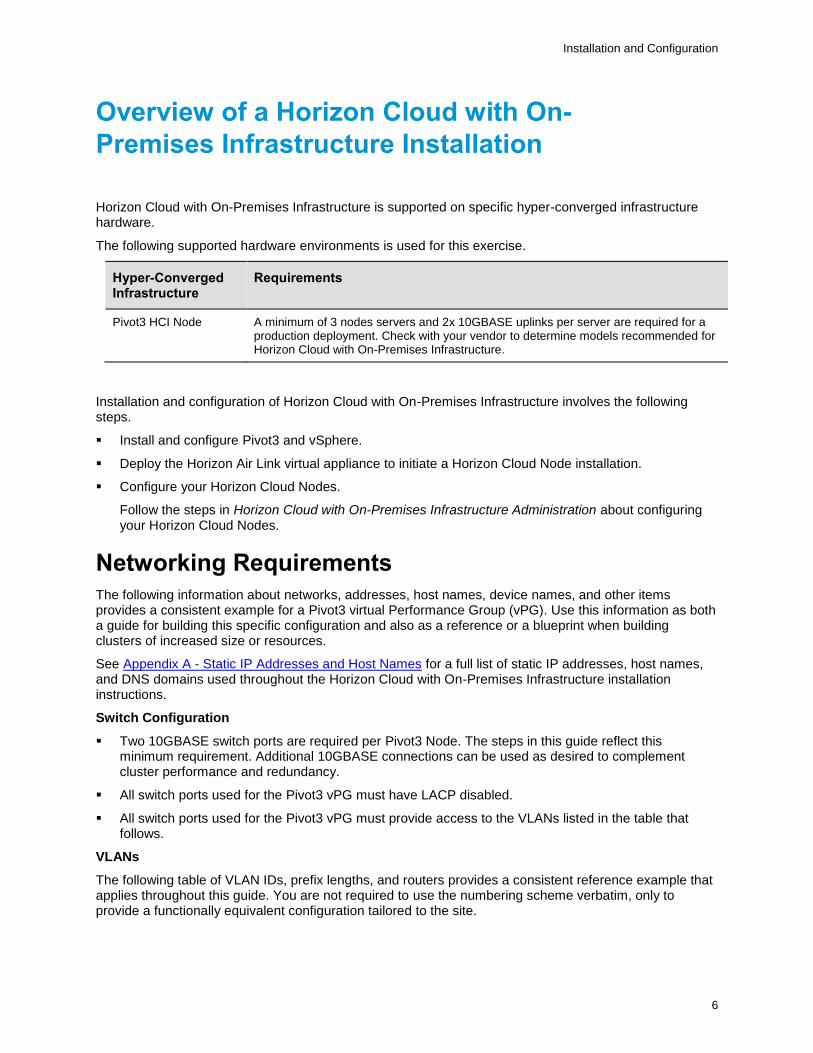
Horizon Cloud with On-Premises Infrastructure is supported on specific hyper-converged infrastructure hardware.
The following supported hardware environments is used for this exercise.
Hyper-Converged Infrastructure
Requirements
Pivot3 HCI Node A minimum of 3 nodes servers and 2x 10GBASE uplinks per server are required for a production deployment. Check with your vendor to determine models recommended for Horizon Cloud with On-Premises Infrastructure.
Installation and configuration of Horizon Cloud with On-Premises Infrastructure involves the following steps.
Install and configure Pivot3 and vSphere.
Deploy the Horizon Air Link virtual appliance to initiate a Horizon Cloud Node installation.
Configure your Horizon Cloud Nodes.
Follow the steps in Horizon Cloud with On-Premises Infrastructure Administration about configuring your Horizon Cloud Nodes.
Networking Requirements
The following information about networks, addresses, host names, device names, and other items provides a consistent example for a Pivot3 virtual Performance Group (vPG). Use this information as both a guide for building this specific configuration and also as a reference or a blueprint when building clusters of increased size or resources.
See Appendix A - Static IP Addresses and Host Names for a full list of static IP addresses, host names, and DNS domains used throughout the Horizon Cloud with On-Premises Infrastructure installation instructions.
Switch Configuration
Two 10GBASE switch ports are required per Pivot3 Node. The steps in this guide reflect this minimum requirement. Additional 10GBASE connections can be used as desired to complement cluster performance and redundancy.
All switch ports used for the Pivot3 vPG must have LACP disabled.
All switch ports used for the Pivot3 vPG must provide access to the VLANs listed in the table that follows.
VLANs
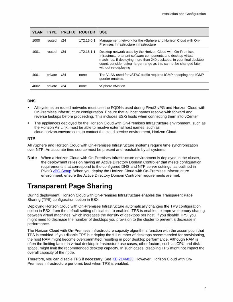
The following table of VLAN IDs, prefix lengths, and routers provides a consistent reference example that applies throughout this guide. You are not required to use the numbering scheme verbatim, only to provide a functionally equivalent configuration tailored to the site.
Installation and Configuration
7
VLAN TYPE PREFIX ROUTER USE
1000 routed /24 172.16.0.1 Management network for the vSphere and Horizon Cloud with On-Premises Infrastructure infrastructure
1001 routed /24 172.16.1.1 Desktop network used by the Horizon Cloud with On-Premises Infrastructure tenant software components and desktop virtual machines. If deploying more than 240 desktops, in your final desktop count, consider using larger range as this cannot be changed later without re-deploying
4001 private /24 none The VLAN used for vSTAC traffic requires IGMP snooping and IGMP querier enabled.
4002 private /24 none vSphere vMotion
DNS
All systems on routed networks must use the FQDNs used during Pivot3 vPG and Horizon Cloud with On-Premises Infrastructure configuration. Ensure that all host names resolve with forward and reverse lookups before proceeding. This includes ESXi hosts when connecting them into vCenter
The appliances deployed for the Horizon Cloud with On-Premises Infrastructure environment, such as the Horizon Air Link, must be able to resolve external host names, such as cloud.horizon.vmware.com, to contact the cloud service environment, Horizon Cloud.
NTP
All vSphere and Horizon Cloud with On-Premises Infrastructure systems require time synchronization over NTP. An accurate time source must be present and reachable by all systems.
Note When a Horizon Cloud with On-Premises Infrastructure environment is deployed in the cluster, the deployment relies on having an Active Directory Domain Controller that meets configuration requirements that correspond to the configured DNS and NTP server settings, as outlined in Pivot3 vPG Setup. When you deploy the Horizon Cloud with On-Premises Infrastructure environment, ensure the Active Directory Domain Controller requirements are met.
Transparent Page Sharing
During deployment, Horizon Cloud with On-Premises Infrastructure enables the Transparent Page Sharing (TPS) configuration option in ESXi.
Deploying Horizon Cloud with On-Premises Infrastructure automatically changes the TPS configuration option in ESXi from the default setting of disabled to enabled. TPS is enabled to improve memory sharing between virtual machines, which increases the density of desktops per host. If you disable TPS, you might need to decrease the number of desktops you provision to the cluster to prevent a decrease in performance.
The Horizon Cloud with On-Premises Infrastructure capacity algorithms function with the assumption that TPS is enabled. If you disable TPS but deploy the full number of desktops recommended for provisioning, the host RAM might become overcommitted, resulting in poor desktop performance. Although RAM is often the limiting factor in virtual desktop infrastructure use cases, other factors, such as CPU and disk space, might limit the recommended desktop capacity. In such cases, disabling TPS might not impact the overall capacity of the node.
Therefore, you can disable TPS if necessary. See KB 2146823. However, Horizon Cloud with On-Premises Infrastructure performs best when TPS is enabled.
Installation and Configuration
8
Installing and Configuring Horizon Cloud
with On-Premises Infrastructure on
Pivot3 Hyperconverged Infrastructure
Section 1 Install Pivot3 vSTAC Nodes
Create a foundation for a fault-tolerant network with Pivot3 vSTAC technology.
Note Some terminology has changed. Arrays have been replaced by virtual Performance Groups (vPGs), and Appliances have been replaced with Nodes.
This section describes how to:
Connect Pivot3 vSTAC Nodes and Ethernet switches to create an iSCSI SAN
Connect Pivot3 vSTAC Nodes to the management network Ethernet switch
Required items for this section:
Pivot3 vSTAC Nodes and latest Pivot3 Hardware Installation Guide
An industry standard 19” data center rack
Two 10 Gigabit Ethernet switches for the Storage Area Networks
An Ethernet switch for the management network, or if connecting to an existing management network, an open switch port on the management network Ethernet switch for each vSTAC Node
Note Pivot3 vSTAC Nodes have two Network Interface Card (NIC) ports dedicated for iSCSI SAN connectivity. Each SAN NIC port must be on a different subnet (no routers).
Note 10GbE is required for SAN switch connections for vSTAC versions 6.5 and above.
Note Pivot3’s system architecture calls for using two physically separate switches for the SAN Networks, each dedicated to a different subnet. This protects the vSTAC vPG from a single switch failure and provides the performance as stated in any Pivot3 testing results. Not following this guideline may result in less-than-optimal system operation in regards to performance and system fault tolerance.
Install Pivot3 vSTAC Nodes
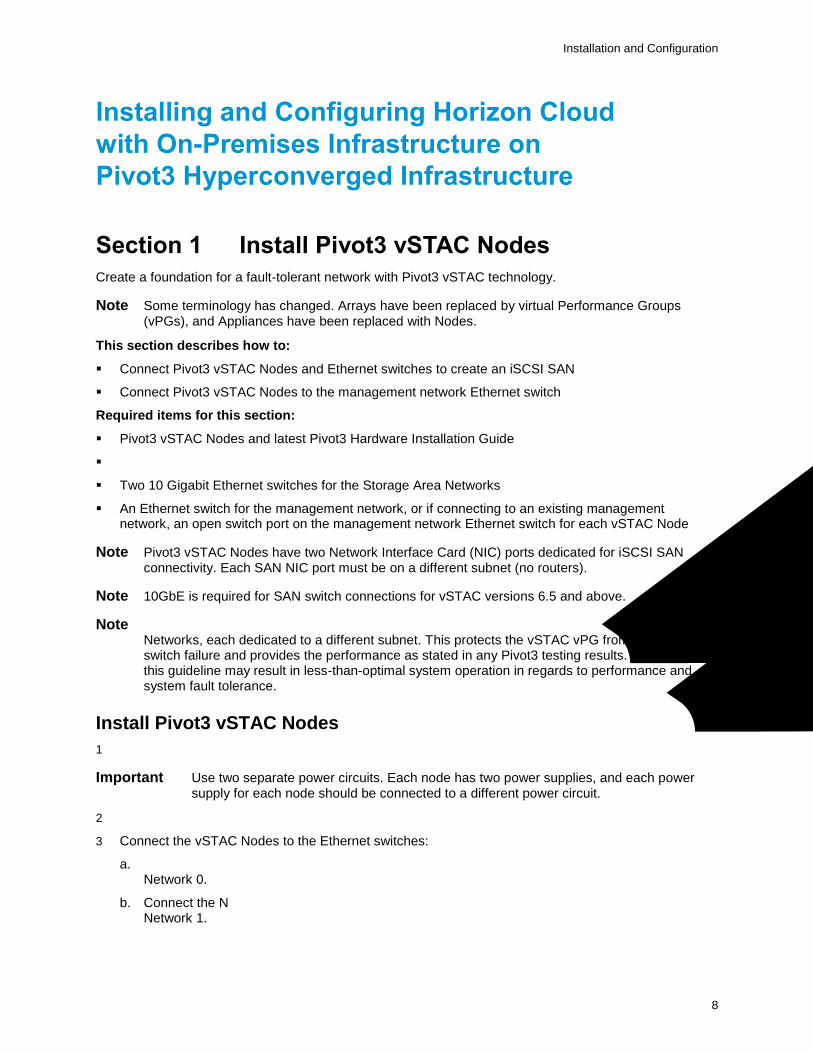
1 Follow the manufacturer’s instructions to install hardware in a 2U rack.
Important Use two separate power circuits. Each node has two power supplies, and each power supply for each node should be connected to a different power circuit.
2 Follow the switch vendor’s instructions to install the Ethernet switches in the rack.
3 Connect the vSTAC Nodes to the Ethernet switches:
a. Connect the NIC ports labeled “SAN Network 0” of all nodes to the Ethernet switch for SAN Network 0.
b. Connect the NIC ports labeled “SAN Network 1” of all nodes to the Ethernet switch for SAN Network 1.
Installation and Configuration
9
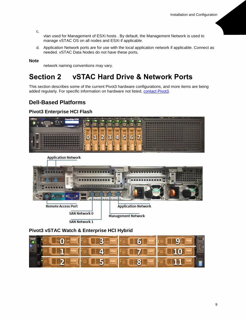
c. Connect the NIC ports labeled “Management Network” of all nodes to the Ethernet switch and vlan used for Management of ESXi hosts . By default, the Management Network is used to manage vSTAC OS on all nodes and ESXi if applicable.
d. Application Network ports are for use with the local application network if applicable. Connect as needed. vSTAC Data Nodes do not have these ports.
Note For simplicity, this guide refers to “SAN Network 0” and “SAN Network 1” throughout. Local network naming conventions may vary.
Section 2 vSTAC Hard Drive & Network Ports
This section describes some of the current Pivot3 hardware configurations, and more items are being added regularly. For specific information on hardware not listed, contact Pivot3.
Dell-Based Platforms
Pivot3 Enterprise HCI Flash
Pivot3 vSTAC Watch & Enterprise HCI Hybrid
Installation and Configuration
10
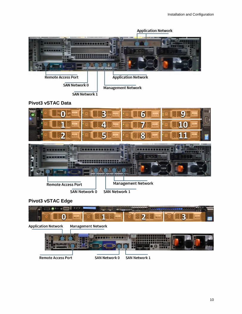
Pivot3 vSTAC Data
Pivot3 vSTAC Edge
Installation and Configuration
11
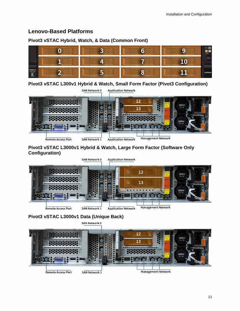
Lenovo-Based Platforms
Pivot3 vSTAC Hybrid, Watch, & Data (Common Front)
Pivot3 vSTAC L300v1 Hybrid & Watch, Small Form Factor (Pivot3 Configuration)
Pivot3 vSTAC L3000v1 Hybrid & Watch, Large Form Factor (Software Only Configuration)
Pivot3 vSTAC L3000v1 Data (Unique Back)
Installation and Configuration
12
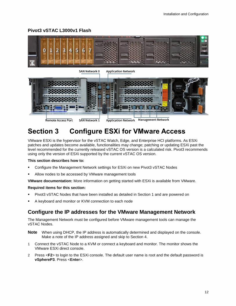
Pivot3 vSTAC L3000v1 Flash
Section 3 Configure ESXi for VMware Access
VMware ESXi is the hypervisor for the vSTAC Watch, Edge, and Enterprise HCI platforms. As ESXi patches and updates become available, functionalities may change; patching or updating ESXi past the level recommended for the currently released vSTAC OS version is a calculated risk. Pivot3 recommends using only the version of ESXi supported by the current vSTAC OS version.
This section describes how to:
Configure the Management Network settings for ESXi on new Pivot3 vSTAC Nodes
Allow nodes to be accessed by VMware management tools
VMware documentation: More information on getting started with ESXi is available from VMware.
Required items for this section:
Pivot3 vSTAC Nodes that have been installed as detailed in Section 1 and are powered on
A keyboard and monitor or KVM connection to each node
Configure the IP addresses for the VMware Management Network
The Management Network must be configured before VMware management tools can manage the vSTAC Nodes.
Note When using DHCP, the IP address is automatically determined and displayed on the console. Make a note of the IP address assigned and skip to Section 4.
1 Connect the vSTAC Node to a KVM or connect a keyboard and monitor. The monitor shows the VMware ESXi direct console.
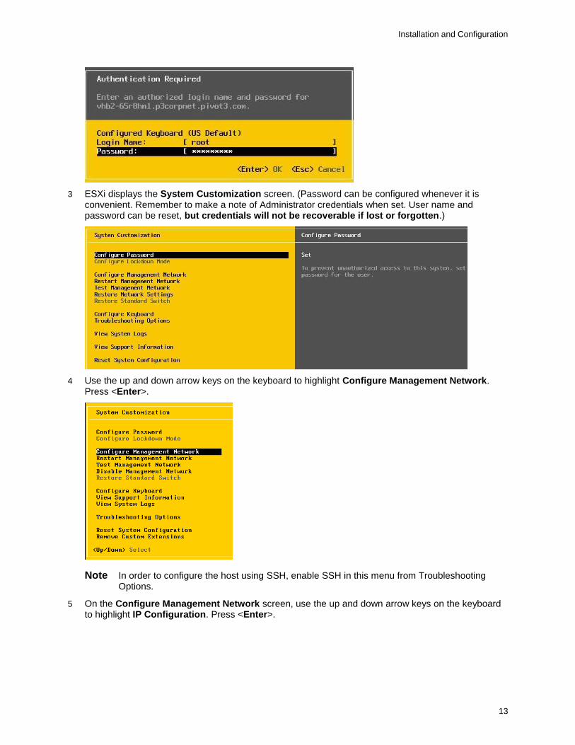
2 Press <F2> to login to the ESXi console. The default user name is root and the default password is vSphereP3. Press <Enter>.
Installation and Configuration
13
3 ESXi displays the System Customization screen. (Password can be configured whenever it is convenient. Remember to make a note of Administrator credentials when set. User name and password can be reset, but credentials will not be recoverable if lost or forgotten.)
4 Use the up and down arrow keys on the keyboard to highlight Configure Management Network. Press <Enter>.
Note In order to configure the host using SSH, enable SSH in this menu from Troubleshooting Options.
5 On the Configure Management Network screen, use the up and down arrow keys on the keyboard to highlight IP Configuration. Press <Enter>.

Installation and Configuration
14
Important Ensure that the chosen Network Adapter is the correct one. Default is Adapter 2, but may vary in the local environment setup.
Note Ensure that, if the management port is a trunk port, the management VLAN has been entered and tagged on the menu.
Note If there is a DHCP server on the VMware Management Network, select the top option in the display dialog, Use dynamic IP address & network configuration. The values for IP Address, Subnet Mask, and Default Gateway will be set dynamically by the DHCP server. Make a note of the IP address for this host.
Note If using Use dynamic IP address & network configuration, ensure that the IP address of the ESXi host does not change on reboot. If the host IP changes on reboot, VMware management tools will not be able to autoconnect to the ESXi host.
6 If there is not a DHCP server on the VMware Management Network, the values for IP Address, Subnet Mask, and Default Gateway must all be manually entered. Select the second option on the display console, Set static IP address and network configuration, and complete the manual entry of values for IP Address, Subnet Mask, and Default Gateway. Make a note of this host’s IP address. Once completed, press <Enter> to return to the Configure Management Network screen.
Installation and Configuration
15
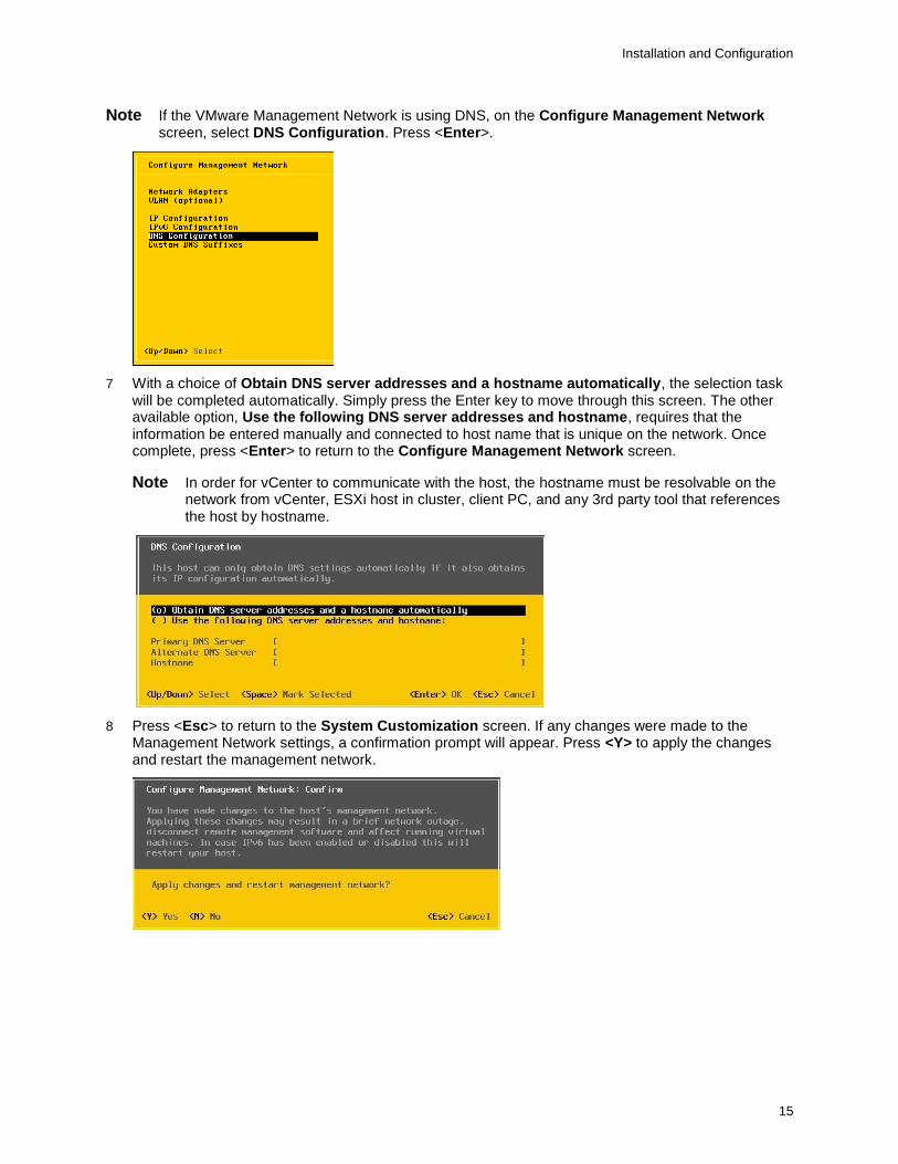
Note If the VMware Management Network is using DNS, on the Configure Management Network screen, select DNS Configuration. Press <Enter>.
7 With a choice of Obtain DNS server addresses and a hostname automatically, the selection task will be completed automatically. Simply press the Enter key to move through this screen. The other available option, Use the following DNS server addresses and hostname, requires that the information be entered manually and connected to host name that is unique on the network. Once complete, press <Enter> to return to the Configure Management Network screen.
Note In order for vCenter to communicate with the host, the hostname must be resolvable on the network from vCenter, ESXi host in cluster, client PC, and any 3rd party tool that references the host by hostname.
8 Press <Esc> to return to the System Customization screen. If any changes were made to the Management Network settings, a confirmation prompt will appear. Press <Y> to apply the changes and restart the management network.
Installation and Configuration
16
Creating a Pivot3 vSTAC vPG
This section explains how to assign Pivot3 vSTAC Nodes to a new Pivot3 vSTAC vPG, name the vPG, and set IP addresses for the Nodes in the vPG.
This section describes how to:
Discover the Pivot3 Nodes in the vSTAC Domain
Create the vSTAC vPG
Required items for this section:
• The user name and password to be initially used for the vPG Administrator, if applicable
• The name to be assigned to the vSTAC vPG
• The IP addressing information (IP addresses, subnet masks, and any applicable default gateways) for the SAN Networks
Create a vPG
Member nodes are combined into a vSTAC vPG, allowing them to be viewed and managed as a single, unified storage system.
Note A node can only be a member of one vSTAC vPG.
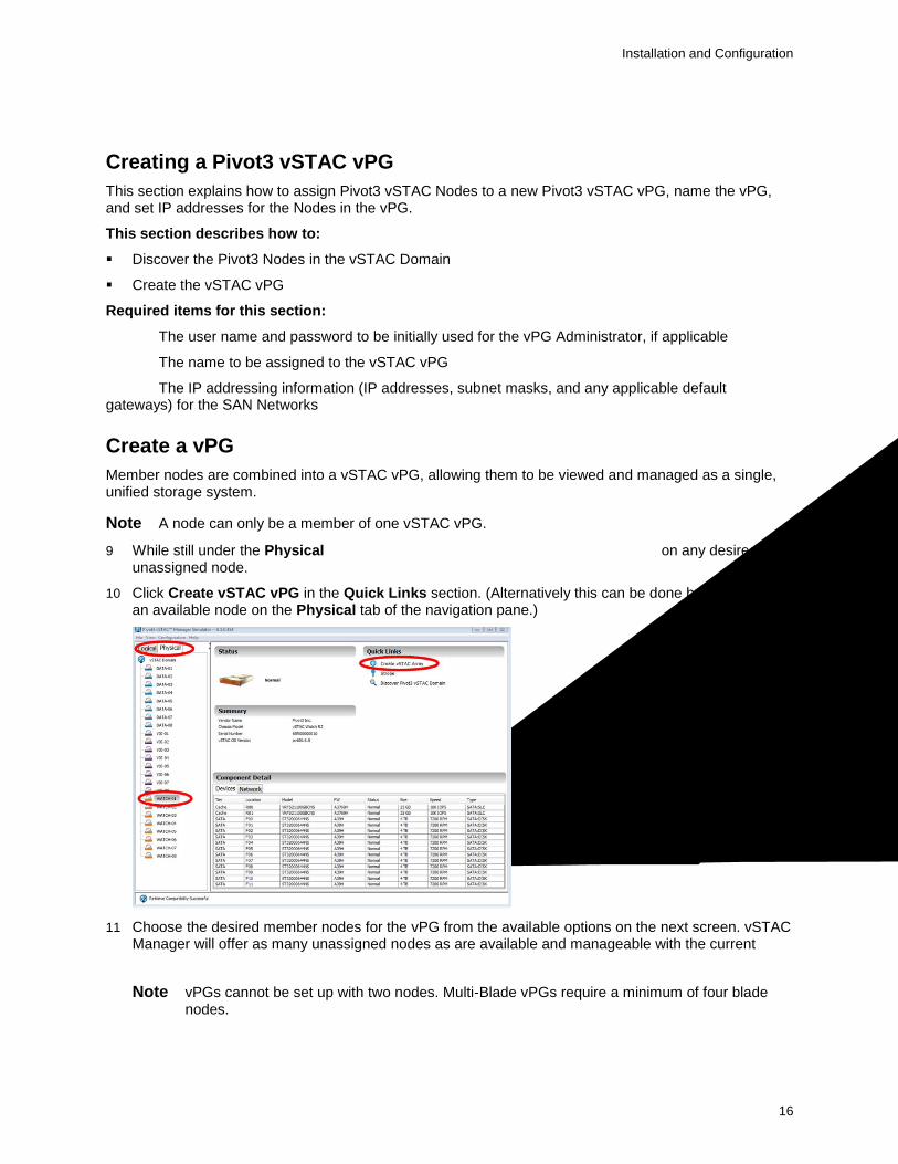
9 While still under the Physical tab of the vSTAC Manager’s navigation pane, click on any desired unassigned node.
10 Click Create vSTAC vPG in the Quick Links section. (Alternatively this can be done by right-clicking an available node on the Physical tab of the navigation pane.)
11 Choose the desired member nodes for the vPG from the available options on the next screen. vSTAC Manager will offer as many unassigned nodes as are available and manageable with the current Administrator’s credentials.
Note vPGs cannot be set up with two nodes. Multi-Blade vPGs require a minimum of four blade nodes.
Installation and Configuration
17
12 Give the vPG a unique name of up to 15 alpha-numeric characters.
Set Hypervisor Credentials
In order to provide support for all features, vSMS and vSTAC OS require administrator-level access to each ESXi hypervisor in the domain.
Note All ESXi hypervisors on the vSTAC vPG member nodes must accept the same login credentials to perform VM configuration operations.
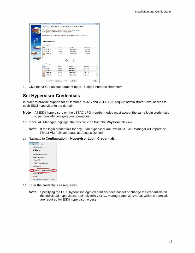
13 In vSTAC Manager, highlight the desired vPG from the Physical tab view.
Note If the login credentials for any ESXi hypervisor are invalid, vSTAC Manager will report the Pivot3 VM Failover status as Access Denied.
14 Navigate to Configuration > Hypervisor Login Credentials.
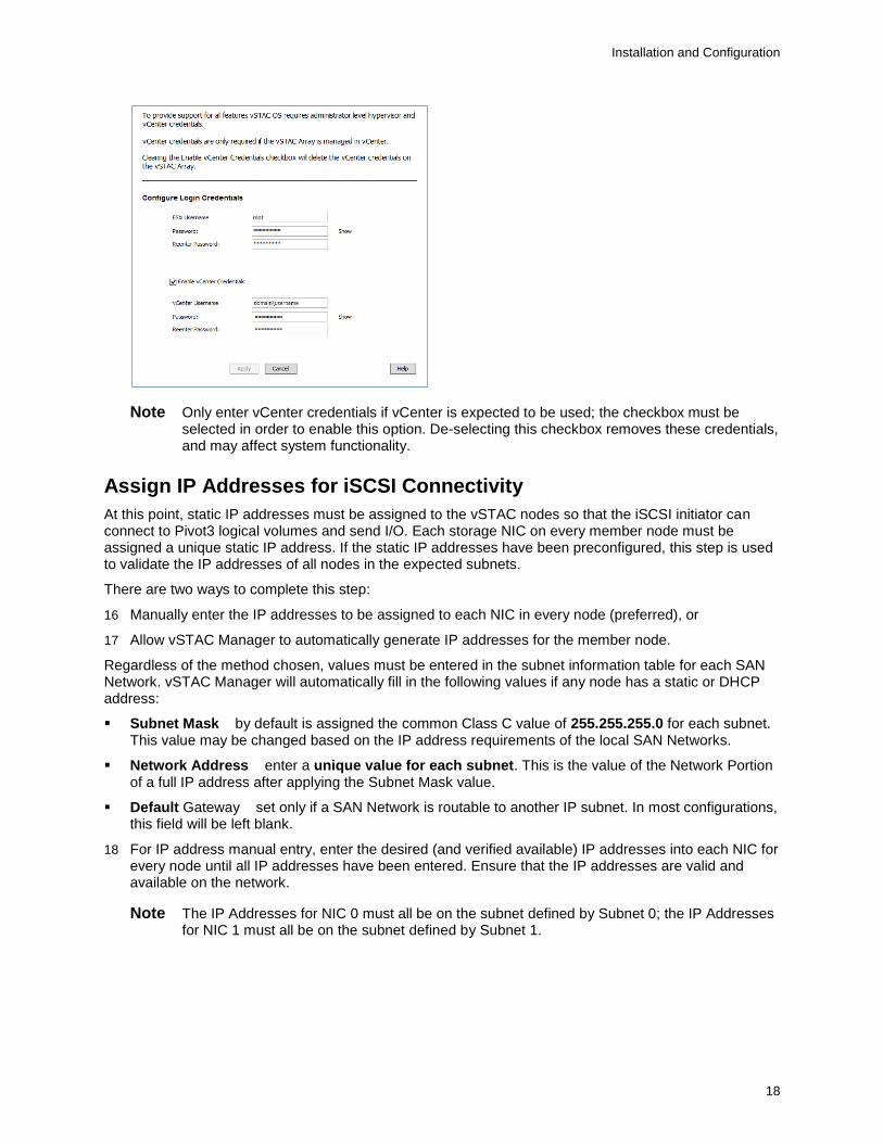
15 Enter the credentials as requested.
Note Specifying the ESXi hypervisor login credentials does not set or change the credentials on the individual hypervisors. It simply tells vSTAC Manager and vSTAC OS which credentials are required for ESXi hypervisor access.
Installation and Configuration
18
Note Only enter vCenter credentials if vCenter is expected to be used; the checkbox must be selected in order to enable this option. De-selecting this checkbox removes these credentials, and may affect system functionality.
Assign IP Addresses for iSCSI Connectivity
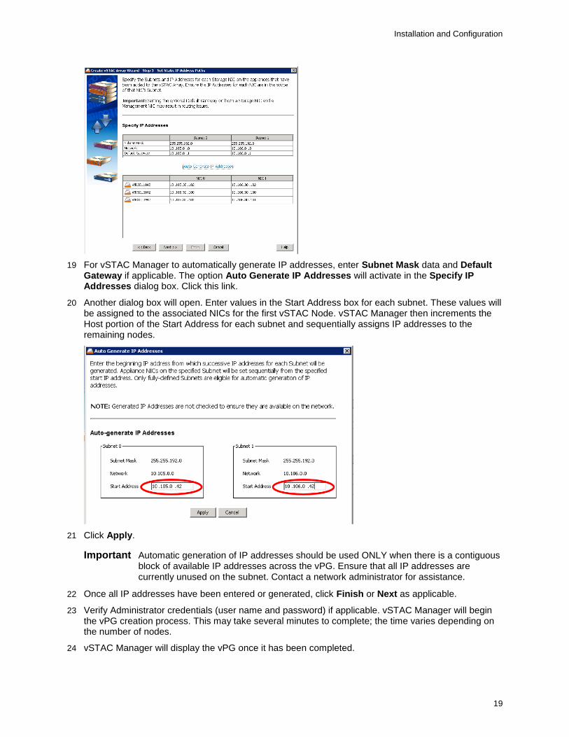
At this point, static IP addresses must be assigned to the vSTAC nodes so that the iSCSI initiator can connect to Pivot3 logical volumes and send I/O. Each storage NIC on every member node must be assigned a unique static IP address. If the static IP addresses have been preconfigured, this step is used to validate the IP addresses of all nodes in the expected subnets.
There are two ways to complete this step:
16 Manually enter the IP addresses to be assigned to each NIC in every node (preferred), or
17 Allow vSTAC Manager to automatically generate IP addresses for the member node.
Regardless of the method chosen, values must be entered in the subnet information table for each SAN Network. vSTAC Manager will automatically fill in the following values if any node has a static or DHCP address:
Subnet Mask – by default is assigned the common Class C value of 255.255.255.0 for each subnet. This value may be changed based on the IP address requirements of the local SAN Networks.
Network Address – enter a unique value for each subnet. This is the value of the Network Portion of a full IP address after applying the Subnet Mask value.
Default Gateway – set only if a SAN Network is routable to another IP subnet. In most configurations, this field will be left blank.
18 For IP address manual entry, enter the desired (and verified available) IP addresses into each NIC for every node until all IP addresses have been entered. Ensure that the IP addresses are valid and available on the network.
Note The IP Addresses for NIC 0 must all be on the subnet defined by Subnet 0; the IP Addresses for NIC 1 must all be on the subnet defined by Subnet 1.
Installation and Configuration
19
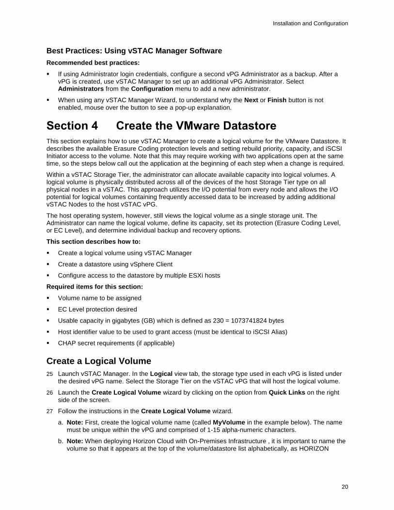
19 For vSTAC Manager to automatically generate IP addresses, enter Subnet Mask data and Default Gateway if applicable. The option Auto Generate IP Addresses will activate in the Specify IP Addresses dialog box. Click this link.
20 Another dialog box will open. Enter values in the Start Address box for each subnet. These values will be assigned to the associated NICs for the first vSTAC Node. vSTAC Manager then increments the Host portion of the Start Address for each subnet and sequentially assigns IP addresses to the remaining nodes.
21 Click Apply.
Important Automatic generation of IP addresses should be used ONLY when there is a contiguous block of available IP addresses across the vPG. Ensure that all IP addresses are currently unused on the subnet. Contact a network administrator for assistance.
22 Once all IP addresses have been entered or generated, click Finish or Next as applicable.
23 Verify Administrator credentials (user name and password) if applicable. vSTAC Manager will begin the vPG creation process. This may take several minutes to complete; the time varies depending on the number of nodes.
24 vSTAC Manager will display the vPG once it has been completed.
Installation and Configuration
20
Best Practices: Using vSTAC Manager Software
Recommended best practices:
If using Administrator login credentials, configure a second vPG Administrator as a backup. After a vPG is created, use vSTAC Manager to set up an additional vPG Administrator. Select Administrators from the Configuration menu to add a new administrator.
When using any vSTAC Manager Wizard, to understand why the Next or Finish button is not enabled, mouse over the button to see a pop-up explanation.
Section 4 Create the VMware Datastore
This section explains how to use vSTAC Manager to create a logical volume for the VMware Datastore. It describes the available Erasure Coding protection levels and setting rebuild priority, capacity, and iSCSI Initiator access to the volume. Note that this may require working with two applications open at the same time, so the steps below call out the application at the beginning of each step when a change is required.
Within a vSTAC Storage Tier, the administrator can allocate available capacity into logical volumes. A logical volume is physically distributed across all of the devices of the host Storage Tier type on all physical nodes in a vSTAC. This approach utilizes the I/O potential from every node and allows the I/O potential for logical volumes containing frequently accessed data to be increased by adding additional vSTAC Nodes to the host vSTAC vPG.
The host operating system, however, still views the logical volume as a single storage unit. The Administrator can name the logical volume, define its capacity, set its protection (Erasure Coding Level, or EC Level), and determine individual backup and recovery options.
This section describes how to:
Create a logical volume using vSTAC Manager
Create a datastore using vSphere Client
Configure access to the datastore by multiple ESXi hosts
Required items for this section:
Volume name to be assigned
EC Level protection desired
Usable capacity in gigabytes (GB) which is defined as 230 = 1073741824 bytes
Host identifier value to be used to grant access (must be identical to iSCSI Alias)
CHAP secret requirements (if applicable)
Create a Logical Volume
25 Launch vSTAC Manager. In the Logical view tab, the storage type used in each vPG is listed under the desired vPG name. Select the Storage Tier on the vSTAC vPG that will host the logical volume.
26 Launch the Create Logical Volume wizard by clicking on the option from Quick Links on the right side of the screen.
27 Follow the instructions in the Create Logical Volume wizard.
a. Note: First, create the logical volume name (called MyVolume in the example below). The name must be unique within the vPG and comprised of 1-15 alpha-numeric characters.
b. Note: When deploying Horizon Cloud with On-Premises Infrastructure , it is important to name the volume so that it appears at the top of the volume/datastore list alphabetically, as HORIZON

Installation and Configuration
21
CLOUD WITH ON-PREMISES INFRASTRUCTURE determines which volume it will use by selecting the first available volume.
c. Note: It is also important that all desktops reside in a single volume, so please consider this during volume creation, in terms of selecting the appropriate EC level for performance and delivering enough capacity to host all possible desktops.
d.
28 Assign the settings to the logical volume.
QoS (Quality of Service) – determines the rebuild priority of the logical volume versus other volumes.
EC Level – Erasure Coding protection levels are provided to meet the data protection goals of each application. Not all supported EC Levels may be available due to node or drive failures, or available capacity constraints. Only the EC Levels compatible with the current drive and volume will be displayed in the drop-down menu.
Usable Capacity – the amount of usable storage for the logical volume. vSTAC Manager uses “GB” and “TB” to mean standards based on binary multiples of the byte. For example, 1 GB in vSMS is 230 bytes. 1 TB in vSMS is 240 bytes.
Single-Node vPG Erasure Coding (EC) Levels
EC Level 1P Disk mirroring within the node.
EC Level 1 Striping with parity.
EC Level 2 Protects against up to two drive failures.
Installation and Configuration
22
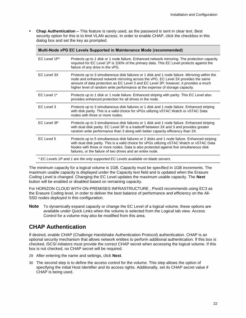
Chap Authentication – This feature is rarely used, as the password is sent in clear text. Best security option for this is to limit VLAN access. In order to enable CHAP, click the checkbox in this dialog box and set the key as prompted.
Multi-Node vPG EC Levels Supported in Maintenance Mode (recommended)
EC Level 1P* Protects up to 1 disk or 1 node failure. Enhanced network mirroring. The protection capacity required for EC Level 1P is 100% of the primary data. This EC Level protects against the failure of any drive in the vPG.
EC Level 3X Protects up to 3 simultaneous disk failures or 1 disk and 1 node failure. Mirroring within the node and enhanced network mirroring across the vPG. EC Level 3X provides the same amount of data protection as EC Level 3 and EC Level 3P; however, it provides a much higher level of random write performance at the expense of storage capacity.
EC Level 1* Protects up to 1 disk or 1 node failure. Enhanced striping with parity. This EC Level also provides enhanced protection for all drives in the node.
EC Level 3 Protects up to 3 simultaneous disk failures or 1 disk and 1 node failure. Enhanced striping with disk parity. This is a valid choice for vPGs utilizing vSTAC Watch or vSTAC Data nodes with three or more nodes.
EC Level 3P Protects up to 3 simultaneous disk failures or 1 disk and 1 node failure. Enhanced striping with dual disk parity. EC Level 3P is a tradeoff between 3X and 3 and provides greater random write performance than 3 along with better capacity efficiency than 3X.
EC Level 5 Protects up to 5 simultaneous disk failures or 2 disks and 1 node failure. Enhanced striping with dual disk parity. This is a valid choice for vPGs utilizing vSTAC Watch or vSTAC Data Nodes with three or more nodes. Data is also protected against five simultaneous disk failures, or the failure of two drives and an entire node.
* EC Levels 1P and 1 are the only supported EC Levels available on blade servers.
The minimum capacity for a logical volume is 1GB. Capacity must be specified in 1GB increments. The maximum usable capacity is displayed under the Capacity text field and is updated when the Erasure Coding Level is changed. Changing the EC Level updates the maximum usable capacity. The Next button will be enabled or disabled based on remaining capacity.
For HORIZON CLOUD WITH ON-PREMISES INFRASTRUCTURE , Pivot3 recommends using EC3 as the Erasure Coding level, in order to deliver the best balance of performance and efficiency on the All-SSD nodes deployed in this configuration.
Note To dynamically expand capacity or change the EC Level of a logical volume, these options are available under Quick Links when the volume is selected from the Logical tab view. Access Control for a volume may also be modified from this area.
CHAP Authentication
If desired, enable CHAP (Challenge Handshake Authentication Protocol) authentication. CHAP is an optional security mechanism that allows network entities to perform additional authentication. If this box is checked, iSCSI initiators must provide the correct CHAP secret when accessing the logical volume. If this box is not checked, no CHAP secret will be required.
29 After entering the name and settings, click Next.
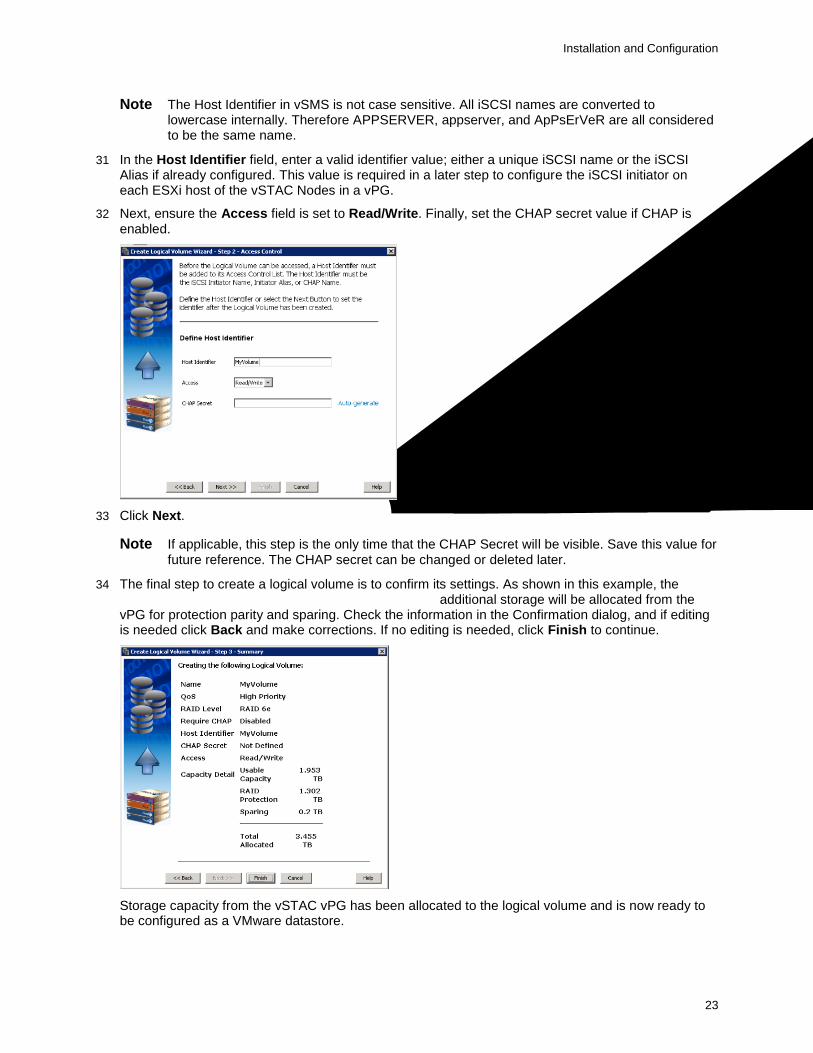
30 The second step is to define the access control for the volume. This step allows the option of specifying the initial Host Identifier and its access rights. Additionally, set its CHAP secret value if CHAP is being used.
Installation and Configuration
23
Note The Host Identifier in vSMS is not case sensitive. All iSCSI names are converted to lowercase internally. Therefore APPSERVER, appserver, and ApPsErVeR are all considered to be the same name.
31 In the Host Identifier field, enter a valid identifier value; either a unique iSCSI name or the iSCSI Alias if already configured. This value is required in a later step to configure the iSCSI initiator on each ESXi host of the vSTAC Nodes in a vPG.
32 Next, ensure the Access field is set to Read/Write. Finally, set the CHAP secret value if CHAP is enabled.
33 Click Next.
Note If applicable, this step is the only time that the CHAP Secret will be visible. Save this value for future reference. The CHAP secret can be changed or deleted later.
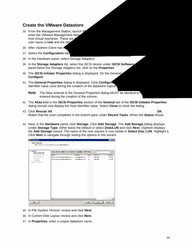
34 The final step to create a logical volume is to confirm its settings. As shown in this example, the logical volume’s capacity is 1.953 TB (3.455 TB total); additional storage will be allocated from the vPG for protection parity and sparing. Check the information in the Confirmation dialog, and if editing is needed click Back and make corrections. If no editing is needed, click Finish to continue.
Storage capacity from the vSTAC vPG has been allocated to the logical volume and is now ready to be configured as a VMware datastore.
Installation and Configuration
24
Create the VMware Datastore
35 From the Management Station, launch VMware vSphere Client. In the IP address / Name: field, enter the VMware Management Network IP address of the first vSTAC Node to be configured that will host virtual machines. These are the ESXi host IP addresses configured in Section 3. The default user name is root and the default password is vSphereP3.
36 After vSphere Client has connected, select the IP address in the left pane.
37 Select the Configuration tab.
38 In the Hardware panel, select Storage Adapters.
39 In the Storage Adapters list, select the iSCSI device under iSCSI Software Adapter. In the Details panel below the Storage Adapters list, click on the Properties… link on the right side of the panel.
40 The iSCSI Initiator Properties dialog is displayed. On the General tab, select the button labeled Configure….
41 The General Properties dialog is displayed. Click Configure... In the iSCSI Alias field, enter the Host Identifier value used during the creation of the datastore logical volume. Select OK to save the alias.
Note The Alias entered in the General Properties dialog MUST be identical to the Host Identifier entered during the creation of the volume.
42 The Alias field in the iSCSI Properties section of the General tab of the iSCSI Initiator Properties dialog should now display the Host Identifier value. Select Close to close the dialog.
43 Click Rescan All… at the top right of the dialog. Leave both boxes checked as default. Click OK. Watch that the scan completes in the bottom pane under Recent Tasks. When the Status shows “Completed,” the new volume should become visible in the dialog.
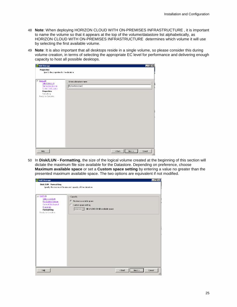
44 Next, in the Hardware panel, click Storage. Click Add Storage. The Add Storage dialog displays. Under Storage Type, either leave the default or select Disk/LUN and click Next. vSphere displays the Add Storage wizard. The name of the new volume is now visible in Select Disc LUN. Highlight it. Click Next to navigate through setting the options in this wizard.
45 In File System Version, review and click Next.
46 In Current Disk Layout, review and click Next.
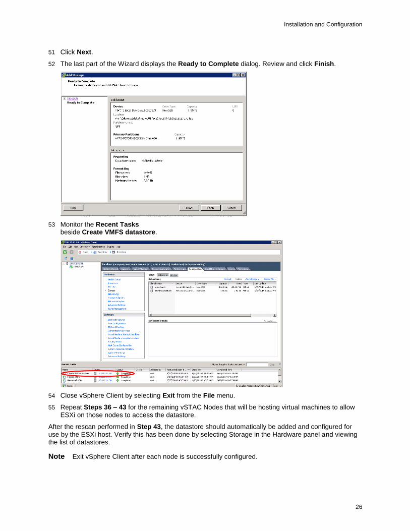
47 In Properties, enter a unique datastore name.
Installation and Configuration
25
48 Note: When deploying HORIZON CLOUD WITH ON-PREMISES INFRASTRUCTURE , it is important to name the volume so that it appears at the top of the volume/datastore list alphabetically, as HORIZON CLOUD WITH ON-PREMISES INFRASTRUCTURE determines which volume it will use by selecting the first available volume.
49 Note: It is also important that all desktops reside in a single volume, so please consider this during volume creation, in terms of selecting the appropriate EC level for performance and delivering enough capacity to host all possible desktops.
50 In Disk/LUN - Formatting, the size of the logical volume created at the beginning of this section will dictate the maximum file size available for the Datastore. Depending on preference, choose Maximum available space or set a Custom space setting by entering a value no greater than the presented maximum available space. The two options are equivalent if not modified.
Installation and Configuration
26
51 Click Next.
52 The last part of the Wizard displays the Ready to Complete dialog. Review and click Finish.
53 Monitor the Recent Tasks pane at the bottom of the vSphere Client dialog for “Completed” to display beside Create VMFS datastore.
54 Close vSphere Client by selecting Exit from the File menu.
55 Repeat Steps 36 – 43 for the remaining vSTAC Nodes that will be hosting virtual machines to allow ESXi on those nodes to access the datastore.
After the rescan performed in Step 43, the datastore should automatically be added and configured for use by the ESXi host. Verify this has been done by selecting Storage in the Hardware panel and viewing the list of datastores.
Note Exit vSphere Client after each node is successfully configured.
Installation and Configuration
27
56 Repeat Steps 1-8 for each of the vSTAC Nodes.
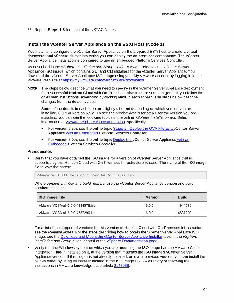
Install the vCenter Server Appliance on the ESXi Host (Node 1)
You install and configure the vCenter Server Appliance on the prepared ESXi host to create a virtual datacenter and vSphere cluster into which you can deploy the on-premises components. The vCenter Server Appliance installation is configured to use an embedded Platform Services Controller.
As described in the vSphere Installation and Setup Guide, VMware releases the vCenter Server Appliance ISO image, which contains GUI and CLI installers for the vCenter Server Appliance. You download the vCenter Server Appliance ISO image using your My VMware account by logging in to the VMware Web site at https://my.vmware.com/web/vmware/downloads.
Note The steps below describe what you need to specify in the vCenter Server Appliance deployment for a successful Horizon Cloud with On-Premises Infrastructure setup. In general, you follow the on-screen instructions. advancing by clicking Next in each screen. The steps below describe changes from the default values.
Some of the details in each step are slightly different depending on which version you are installing, 6.0.n or version 6.5.n. To see the precise details for step 6 for the version you are installing, you can see the following topics in the online vSphere Installation and Setup information at VMware vSphere 6 Documentation, specifically:
For version 6.5.n, see the online topic Stage 1 - Deploy the OVA File as a vCenter Server Appliance with an Embedded Platform Services Controller.
For version 6.0.n, see the online topic Deploy the vCenter Server Appliance with an Embedded Platform Services Controller.
Prerequisites
Verify that you have obtained the ISO image for a version of vCenter Server Appliance that is supported by this Horizon Cloud with On-Premises Infrastructure release. The name of the ISO image file follows the pattern:
VMware-VCSA-all-version_number-build_number.iso
Where version_number and build_number are the vCenter Server Appliance version and build numbers, such as:
ISO Image File Version Build
VMware-VCSA-all-6.5.0-4944578.iso 6.5.0 4944578
VMware-VCSA-all-6.0.0-4637290.iso 6.0.0 4637290
For a list of the supported versions for this version of Horizon Cloud with On-Premises Infrastructure, see the Release Notes. For the steps describing how to obtain the vCenter Server Appliance ISO image, see the Download and Mount the vCenter Server Appliance Installer topic in the vSphere Installation and Setup guide located at the vSphere Documentation page.
Verify that the Windows system on which you are mounting the ISO image has the VMware Client Integration Plug-in installed on it, at the version that matches the ISO image's vCenter Server Appliance version. If the plug-in is not already installed, or is at a previous version, you can install the
plug-in either by using its installer located in the ISO image's/vcsa directory or following the
instructions in VMware knowledge base article 2145066.
Installation and Configuration
28
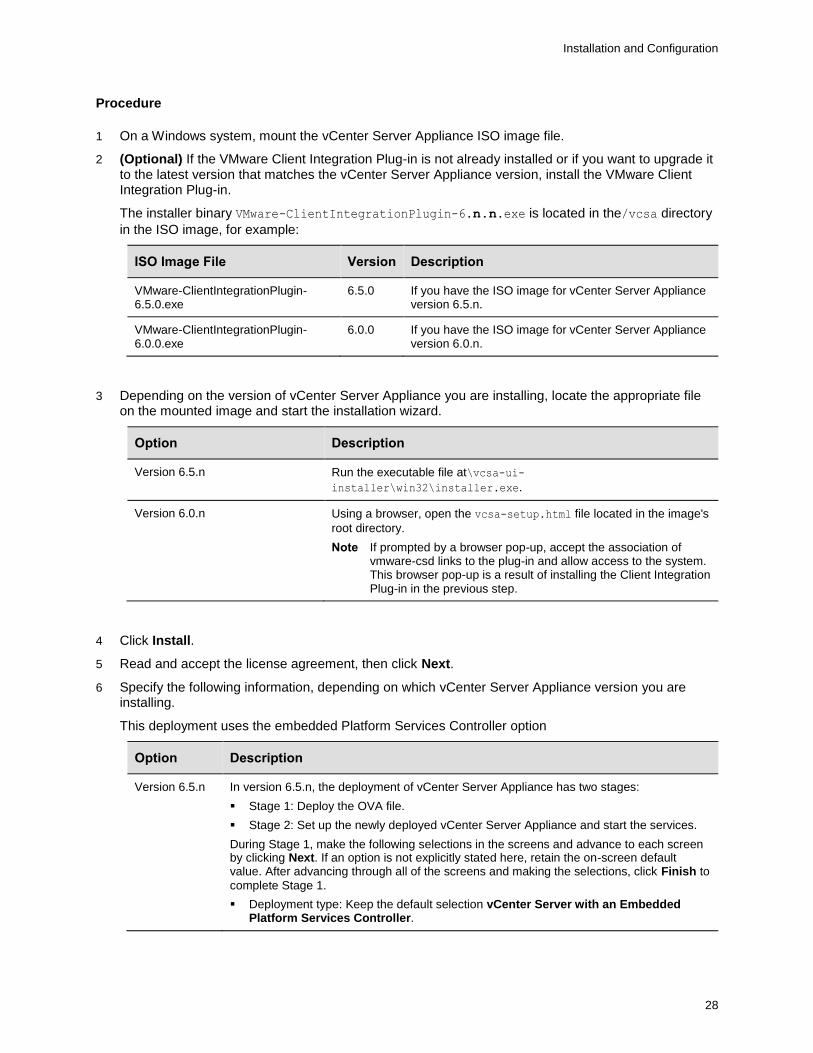
Procedure
1 On a Windows system, mount the vCenter Server Appliance ISO image file.
2 (Optional) If the VMware Client Integration Plug-in is not already installed or if you want to upgrade it to the latest version that matches the vCenter Server Appliance version, install the VMware Client Integration Plug-in.
The installer binary VMware-ClientIntegrationPlugin-6.n.n.exe is located in the/vcsa directory
in the ISO image, for example:
ISO Image File Version Description
VMware-ClientIntegrationPlugin-6.5.0.exe
6.5.0 If you have the ISO image for vCenter Server Appliance version 6.5.n.
VMware-ClientIntegrationPlugin-6.0.0.exe
6.0.0 If you have the ISO image for vCenter Server Appliance version 6.0.n.
3 Depending on the version of vCenter Server Appliance you are installing, locate the appropriate file on the mounted image and start the installation wizard.
Option Description
Version 6.5.n Run the executable file at\vcsa-ui-
installer\win32\installer.exe.
Version 6.0.n Using a browser, open the vcsa-setup.html file located in the image's
root directory.
Note If prompted by a browser pop-up, accept the association of vmware-csd links to the plug-in and allow access to the system. This browser pop-up is a result of installing the Client Integration Plug-in in the previous step.
4 Click Install.
5 Read and accept the license agreement, then click Next.
6 Specify the following information, depending on which vCenter Server Appliance version you are installing.
This deployment uses the embedded Platform Services Controller option
Option Description
Version 6.5.n In version 6.5.n, the deployment of vCenter Server Appliance has two stages:
Stage 1: Deploy the OVA file.
Stage 2: Set up the newly deployed vCenter Server Appliance and start the services.
During Stage 1, make the following selections in the screens and advance to each screen by clicking Next. If an option is not explicitly stated here, retain the on-screen default value. After advancing through all of the screens and making the selections, click Finish to
complete Stage 1.
Deployment type: Keep the default selection vCenter Server with an Embedded Platform Services Controller.
Installation and Configuration
29
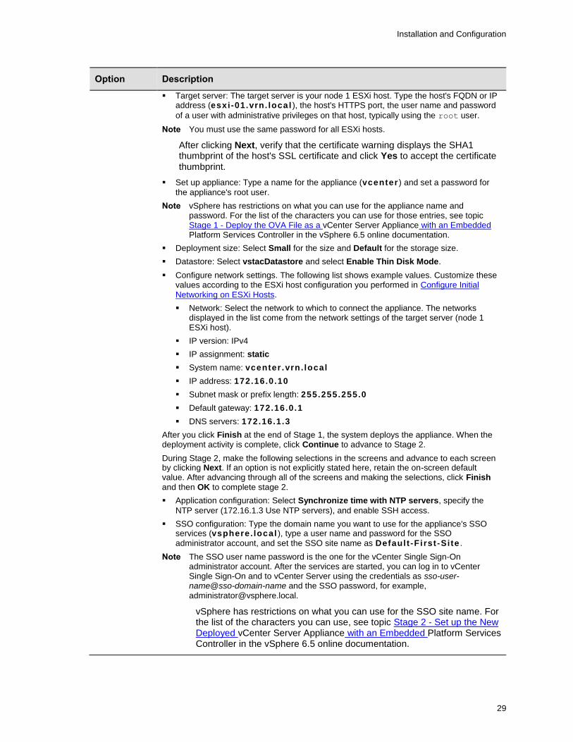
Option Description
Target server: The target server is your node 1 ESXi host. Type the host's FQDN or IP address (esxi-01.vrn. loca l ), the host's HTTPS port, the user name and password
of a user with administrative privileges on that host, typically using the root user.
Note You must use the same password for all ESXi hosts.
After clicking Next, verify that the certificate warning displays the SHA1 thumbprint of the host's SSL certificate and click Yes to accept the certificate thumbprint.
Set up appliance: Type a name for the appliance (vcenter ) and set a password for
the appliance's root user.
Note vSphere has restrictions on what you can use for the appliance name and password. For the list of the characters you can use for those entries, see topic Stage 1 - Deploy the OVA File as a vCenter Server Appliance with an Embedded Platform Services Controller in the vSphere 6.5 online documentation.
Deployment size: Select Small for the size and Default for the storage size.
Datastore: Select vstacDatastore and select Enable Thin Disk Mode.
Configure network settings. The following list shows example values. Customize these values according to the ESXi host configuration you performed in Configure Initial Networking on ESXi Hosts.
Network: Select the network to which to connect the appliance. The networks displayed in the list come from the network settings of the target server (node 1 ESXi host).
IP version: IPv4
IP assignment: static
System name: vcenter .vrn . local
IP address: 172.16.0.10
Subnet mask or prefix length: 255.255.255.0
Default gateway: 172.16.0.1
DNS servers: 172.16.1.3
After you click Finish at the end of Stage 1, the system deploys the appliance. When the deployment activity is complete, click Continue to advance to Stage 2.
During Stage 2, make the following selections in the screens and advance to each screen by clicking Next. If an option is not explicitly stated here, retain the on-screen default value. After advancing through all of the screens and making the selections, click Finish and then OK to complete stage 2.
Application configuration: Select Synchronize time with NTP servers, specify the
NTP server (172.16.1.3 Use NTP servers), and enable SSH access.
SSO configuration: Type the domain name you want to use for the appliance's SSO services (vsphere. local ), type a user name and password for the SSO administrator account, and set the SSO site name as Default -Fi rst -Site .
Note The SSO user name password is the one for the vCenter Single Sign-On administrator account. After the services are started, you can log in to vCenter Single Sign-On and to vCenter Server using the credentials as sso-user-name@sso-domain-name and the SSO password, for example, [email protected].
vSphere has restrictions on what you can use for the SSO site name. For the list of the characters you can use, see topic Stage 2 - Set up the New Deployed vCenter Server Appliance with an Embedded Platform Services Controller in the vSphere 6.5 online documentation.
Installation and Configuration
30
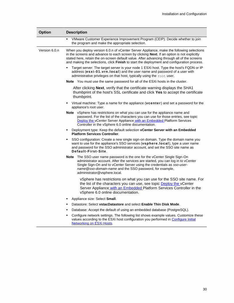
Option Description
VMware Customer Experience Improvement Program (CEIP): Decide whether to join the program and make the appropriate selection.
Version 6.0.n When you deploy version 6.0.n of vCenter Server Appliance, make the following selections in the screens and advance to each screen by clicking Next. If an option is not explicitly
stated here, retain the on-screen default value. After advancing through all of the screens and making the selections, click Finish to start the deployment and configuration process.
Target server: The target server is your node 1 ESXi host. Type the host's FQDN or IP address (esxi-01.vrn. loca l ) and the user name and password of a user with
administrative privileges on that host, typically using the root user.
Note You must use the same password for all of the ESXi hosts in the cluster.
After clicking Next, verify that the certificate warning displays the SHA1 thumbprint of the host's SSL certificate and click Yes to accept the certificate thumbprint.
Virtual machine: Type a name for the appliance (vcenter ) and set a password for the
appliance's root user.
Note vSphere has restrictions on what you can use for the appliance name and password. For the list of the characters you can use for those entries, see topic Deploy the vCenter Server Appliance with an Embedded Platform Services Controller in the vSphere 6.0 online documentation.
Deployment type: Keep the default selection vCenter Server with an Embedded Platform Services Controller.
SSO configuration: Create a new single sign-on domain. Type the domain name you want to use for the appliance's SSO services (vsphere. local ), type a user name
and password for the SSO administrator account, and set the SSO site name as Defaul t -Fi rst -Site .
Note The SSO user name password is the one for the vCenter Single Sign-On administrator account. After the services are started, you can log in to vCenter Single Sign-On and to vCenter Server using the credentials as sso-user-name@sso-domain-name and the SSO password, for example,
vSphere has restrictions on what you can use for the SSO site name. For the list of the characters you can use, see topic Deploy the vCenter Server Appliance with an Embedded Platform Services Controller in the vSphere 6.0 online documentation.
Appliance size: Select Small.
Datastore: Select vstacDatastore and select Enable Thin Disk Mode.
Database: Accept the default of using an embedded database (PostgreSQL).
Configure network settings. The following list shows example values. Customize these values according to the ESXi host configuration you performed in Configure Initial Networking on ESXi Hosts.

Installation and Configuration
31
Option Description
Network: Select the network to which to connect the appliance. The networks displayed in the list come from the network settings of the target server (node 1 ESXi host).
IP address family: IPv4
Network type: static
Network address: 172.16.0.10
System name: vcenter .vrn . local
Subnet mask: 255.255.255.0
Network gateway: 172.16.0.1
Network DNS servers: 172.16.1.3
Configure time sync: 172.16.1.3 (Use NTP servers)
Enable SSH (set enabled)
VMware Customer Experience Improvement Program (CEIP): Decide whether to join the program and make the appropriate selection.
7 When the installation process is finished, exit the installation wizard and unmount the ISO image.
Create a Virtual Data Center and Add a Distributed Virtual Switch and Distributed Port Groups
Unlike the default deployment of HORIZON CLOUD WITH ON-PREMISES INFRASTRUCTURE , when running on the Pivot 3 solution, there will be three standard switches present outside the distributed virtual switches used for the virtual desktops and HORIZON CLOUD WITH ON-PREMISES INFRASTRUCTURE management servers. These include a vm network port group for San 0 and San 1, a vmk port for both the San ports and lastly a private bewitch for intra host communication. It is fully unsupported to migrate these to dvSwitches.
In the vCenter Server environment, you must create a virtual data center and create a distributed virtual switch and distributed port groups for that data center.
Important Horizon Cloud with On-Premises Infrastructure is not supported for use in a vCenter Server environment that has more than one virtual data center configured in it. That data center is the Pivot3 vSTAC cluster. When you set up Horizon Cloud with On-Premises Infrastructure in the vCenter Server environment, ensure that the environment contains only one data center before deploying the Horizon Air Link into the environment.
Procedure
1 In the vSphere Web Client, create a single data center named VRN-DC.
2 Add hosts to the data center.
a Under datacenters, select VRN-DC and Add Host.
b Add esxi-01.vrn.local followed by all remaining hosts to the VDC using defaults.
Note You must use FQDNs when you add the ESXi hosts.
3 Create a single distributed switch named dvSwitch0 for the data center VRN-DC and configure the switch settings.
The distributed switch version you use depends on the version of vCenter Server Appliance you are using.
Installation and Configuration
32
dvSwitch0 Option
vCenter Server Appliance Version 6.5.n
vCenter Server Appliance Version 6.0.n
Version 6.5.n 6.0.n
Number of uplinks
Two Two
Create default port group
Deselect this option. Deselect this option.
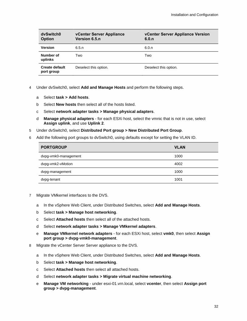
4 Under dvSwitch0, select Add and Manage Hosts and perform the following steps.
a Select task > Add hosts.
b Select New hosts then select all of the hosts listed.
c Select network adapter tasks > Manage physical adapters.
d Manage physical adapters - for each ESXi host, select the vmnic that is not in use, select Assign uplink, and use Uplink 2.
5 Under dvSwitch0, select Distributed Port group > New Distributed Port Group.
6 Add the following port groups to dvSwitch0, using defaults except for setting the VLAN ID.
PORTGROUP VLAN
dvpg-vmk0-management 1000
dvpg-vmk2-vMotion 4002
dvpg-management 1000
dvpg-tenant 1001
7 Migrate VMkernel interfaces to the DVS.
a In the vSphere Web Client, under Distributed Switches, select Add and Manage Hosts.
b Select task > Manage host networking.
c Select Attached hosts then select all of the attached hosts.
d Select network adapter tasks > Manage VMkernel adapters.
e Manage VMkernel network adapters - for each ESXi host, select vmk0, then select Assign port group > dvpg-vmk0-management.
8 Migrate the vCenter Server Server appliance to the DVS.
a In the vSphere Web Client, under Distributed Switches, select Add and Manage Hosts.
b Select task > Manage host networking.
c Select Attached hosts then select all attached hosts.
d Select network adapter tasks > Migrate virtual machine networking.
e Manage VM networking - under esxi-01.vrn.local, select vcenter, then select Assign port group > dvpg-management.

Installation and Configuration
33
9 Remove vSwitch0 from all nodes1.
[root@esxi-01:~] esxcli network vswitch standard portgroup remove --portgroup-
name="VM Network" --vswitch-name=vSwitch0
[root@esxi-01:~] esxcli network vswitch standard uplink remove --uplink-name=vmnic2
--vswitch-name=vSwitch0
[root@esxi-01:~] esxcli network vswitch standard uplink remove --uplink-name=vmnic3
--vswitch-name=vSwitch0
[root@esxi-01:~] esxcli network vswitch standard remove --vswitch-name=vSwitch0
10 Add a second physical network adapter to the DVS.
a In the vSphere Web Client, under Distributed Switches, select Add and Manage Hosts.
b Select task > Manage host networking.
c Select Attached hosts then select all attached hosts.
d Select network adapter tasks > Manage physical adapters.
e Manage physical network adapters. For each ESXi host, select the vmnic that is not in use, then select Assign uplink and use Uplink 1.
11 Add VMkernel adapters for vSphere vMotion and vSTAC.
a In the vSphere Web Client, under Distributed Switches, select Add and Manage Hosts.
b Select task > Manage host networking.
c Select Attached hosts and then select all the attached hosts.
d Select network adapter tasks > Manage VMkernel adapters.
e Configure the network adapters under Manage VMkernel network adapters.
a Repeat this procedure for all hosts.
b On esxi-01.vrn.local, select New adapter.
c Select target device - Select an existing network and select dvpg-vmk4-vMotion.
d IPv4 settings - Set the static IP address to 192.168.1.11 and netmask to 255.255.255.0.
The following image is an example of the topology page for dvSwitch0 in a Pivot3vPG environment.
Create the vSphere Cluster
To establish failover protection, create a vSphere Cluster.
1 It Is important to note that while vSwitch0 can be deleted, vSwitch 1, vSwitch 2, and vSwitch3 are Pivot3 vSwitches and should not be deleted or renamed as per Pivot3 best practices
Installation and Configuration
34
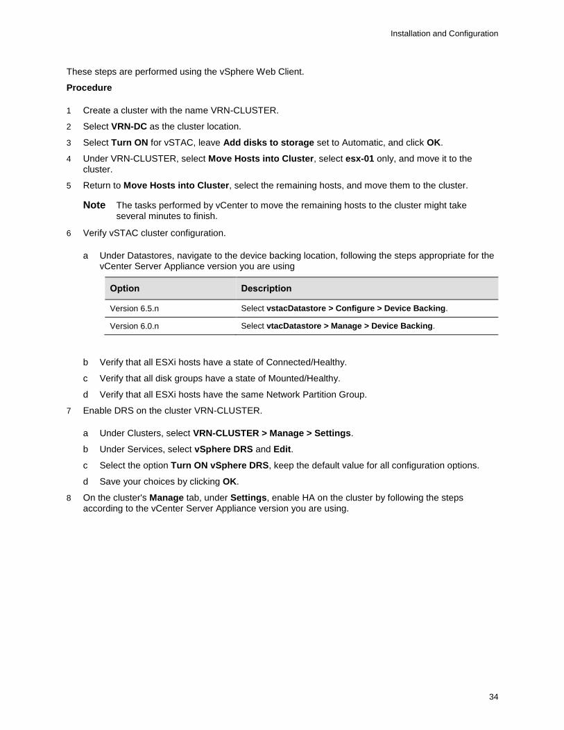
These steps are performed using the vSphere Web Client.
Procedure
1 Create a cluster with the name VRN-CLUSTER.
2 Select VRN-DC as the cluster location.
3 Select Turn ON for vSTAC, leave Add disks to storage set to Automatic, and click OK.
4 Under VRN-CLUSTER, select Move Hosts into Cluster, select esx-01 only, and move it to the cluster.
5 Return to Move Hosts into Cluster, select the remaining hosts, and move them to the cluster.
Note The tasks performed by vCenter to move the remaining hosts to the cluster might take several minutes to finish.
6 Verify vSTAC cluster configuration.
a Under Datastores, navigate to the device backing location, following the steps appropriate for the vCenter Server Appliance version you are using
Option Description
Version 6.5.n Select vstacDatastore > Configure > Device Backing.
Version 6.0.n Select vtacDatastore > Manage > Device Backing.
b Verify that all ESXi hosts have a state of Connected/Healthy.
c Verify that all disk groups have a state of Mounted/Healthy.
d Verify that all ESXi hosts have the same Network Partition Group.
7 Enable DRS on the cluster VRN-CLUSTER.
a Under Clusters, select VRN-CLUSTER > Manage > Settings.
b Under Services, select vSphere DRS and Edit.
c Select the option Turn ON vSphere DRS, keep the default value for all configuration options.
d Save your choices by clicking OK.
8 On the cluster's Manage tab, under Settings, enable HA on the cluster by following the steps according to the vCenter Server Appliance version you are using.
Installation and Configuration
35
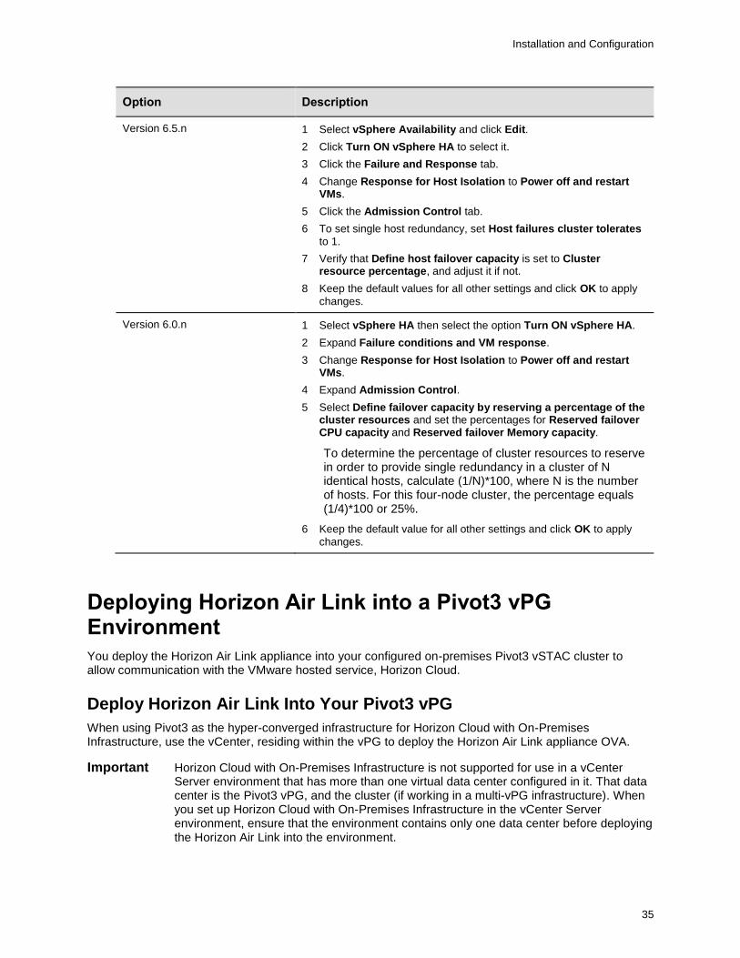
Option Description
Version 6.5.n
1 Select vSphere Availability and click Edit.
2 Click Turn ON vSphere HA to select it.
3 Click the Failure and Response tab.
4 Change Response for Host Isolation to Power off and restart VMs.
5 Click the Admission Control tab.
6 To set single host redundancy, set Host failures cluster tolerates
to 1.
7 Verify that Define host failover capacity is set to Cluster resource percentage, and adjust it if not.
8 Keep the default values for all other settings and click OK to apply
changes.
Version 6.0.n
1 Select vSphere HA then select the option Turn ON vSphere HA.
2 Expand Failure conditions and VM response.
3 Change Response for Host Isolation to Power off and restart VMs.
4 Expand Admission Control.
5 Select Define failover capacity by reserving a percentage of the cluster resources and set the percentages for Reserved failover CPU capacity and Reserved failover Memory capacity.
To determine the percentage of cluster resources to reserve in order to provide single redundancy in a cluster of N identical hosts, calculate (1/N)*100, where N is the number of hosts. For this four-node cluster, the percentage equals (1/4)*100 or 25%.
6 Keep the default value for all other settings and click OK to apply
changes.
Deploying Horizon Air Link into a Pivot3 vPG Environment
You deploy the Horizon Air Link appliance into your configured on-premises Pivot3 vSTAC cluster to allow communication with the VMware hosted service, Horizon Cloud.
Deploy Horizon Air Link Into Your Pivot3 vPG
When using Pivot3 as the hyper-converged infrastructure for Horizon Cloud with On-Premises Infrastructure, use the vCenter, residing within the vPG to deploy the Horizon Air Link appliance OVA.
Important Horizon Cloud with On-Premises Infrastructure is not supported for use in a vCenter Server environment that has more than one virtual data center configured in it. That data center is the Pivot3 vPG, and the cluster (if working in a multi-vPG infrastructure). When you set up Horizon Cloud with On-Premises Infrastructure in the vCenter Server environment, ensure that the environment contains only one data center before deploying the Horizon Air Link into the environment.
Installation and Configuration
36
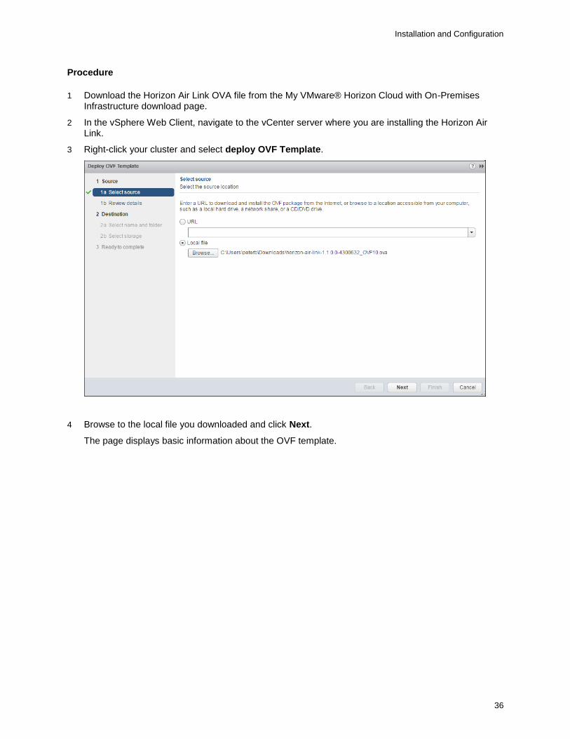
Procedure
1 Download the Horizon Air Link OVA file from the My VMware® Horizon Cloud with On-Premises Infrastructure download page.
2 In the vSphere Web Client, navigate to the vCenter server where you are installing the Horizon Air Link.
3 Right-click your cluster and select deploy OVF Template.
4 Browse to the local file you downloaded and click Next.
The page displays basic information about the OVF template.
Installation and Configuration
37
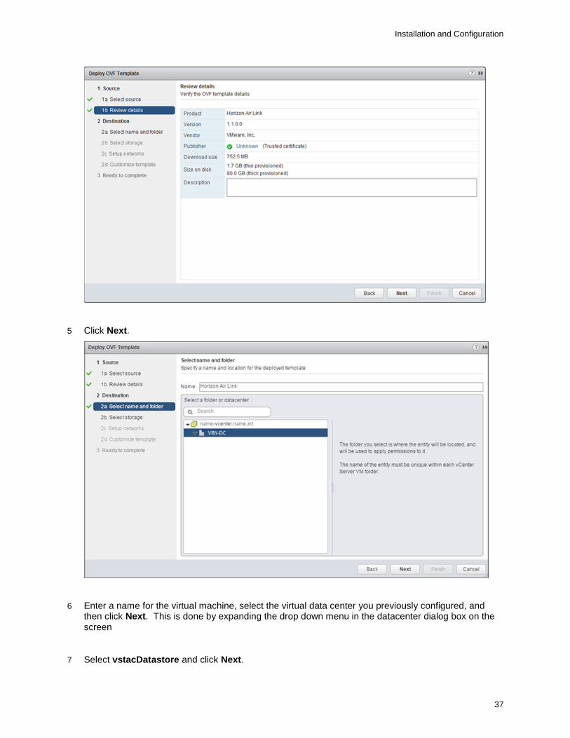
5 Click Next.
6 Enter a name for the virtual machine, select the virtual data center you previously configured, and then click Next. This is done by expanding the drop down menu in the datacenter dialog box on the screen
7 Select vstacDatastore and click Next.
Installation and Configuration
38
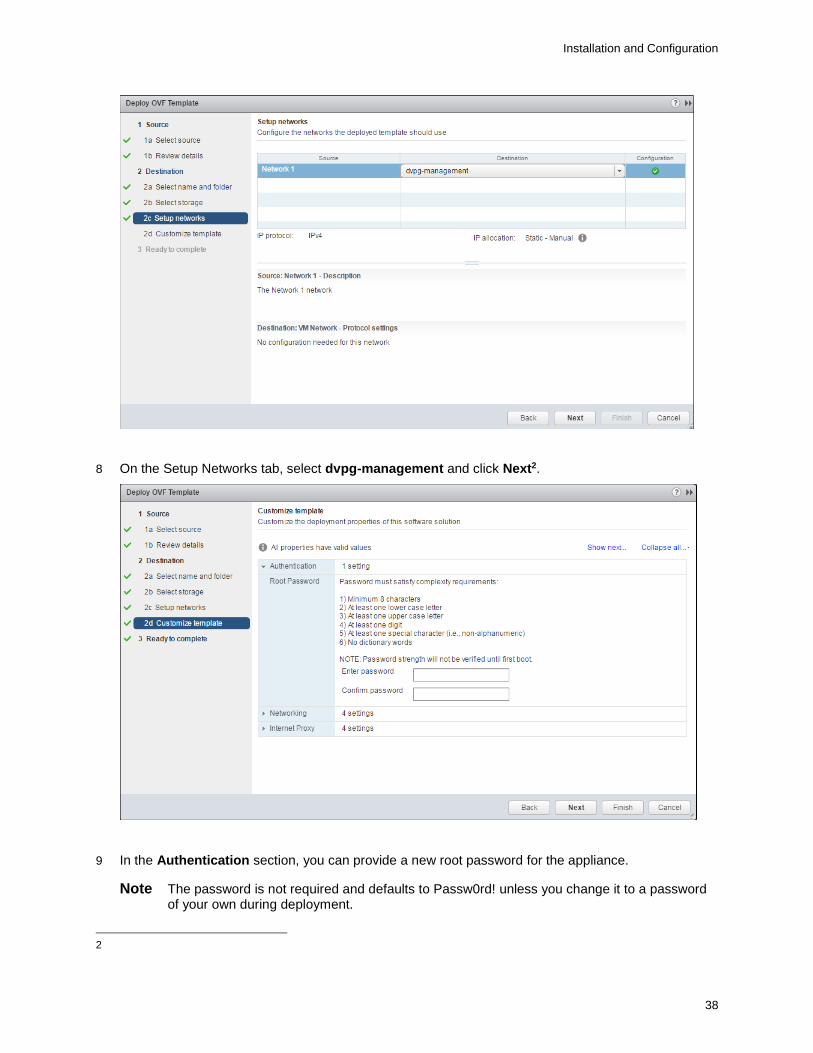
8 On the Setup Networks tab, select dvpg-management and click Next2.
9 In the Authentication section, you can provide a new root password for the appliance.
Note The password is not required and defaults to Passw0rd! unless you change it to a password of your own during deployment.
2

Installation and Configuration
39
10 In the Networking section, if you want to configure the appliance using DHCP, leave the IP address, Netmask, Default Gateway, and DNS Servers text boxes blank. Otherwise, provide values for the text boxes to statically configure the values.
For the DHCP option, confirm that DHCP is configured on the network you choose to deploy to.
11 If your deployment requires you to configure a proxy server for outbound Internet access, in the Internet Proxy section, enter values in the Proxy Server, Proxy Port, Proxy Username, and Proxy Password text boxes. If your deployment does not require you to configure a proxy server, leave the text boxes blank.
Installation and Configuration
40
12 Click Next.
13 Select the Power on after deployment check box and click Finish.
After a few minutes, the appliance deploys.
14 Open the console for the virtual machine.
The console window displays the URL of the Horizon Cloud with On-Premises Infrastructure Administration Console. The link is in the format of https://HAL-IP-address:8443, where HAL-IP-address represents the IP address of your Horizon Air Link appliance.
15 Open a browser window, enter the URL, and when the Administration Console opens, bookmark the URL for future use.
The deployment and configuration of the Horizon Air Link appliance is finished. See the Horizon Cloud with On-Premises Infrastructure Administration document for instructions about configuring Horizon Cloud with On-Premises Infrastructure.
Modify the HA Cluster Admission Criteria
Update the HA cluster admission criteria to maintain the current level of cluster-node redundancy.
The method for determining HA admission criteria is identical to the method previously provided. The method requires that the hardware used across the hosts in the cluster is identical.
Procedure
1 In the vSphere Web Client, under Clusters, select VRN-CLUSTER > Settings.
2 Expand the Admission Control section.
3 Select Define failover capacity by reserving a percentage of the cluster resources.
4 Determine and apply HA admission criteria.
5 To determine the percentage of cluster resources to reserve to provide single-redundancy in a cluster of N identical hosts, calculate (1/N)*100, where N is the number of hosts.
For a four-node cluster, the percentage equals (1/4)*100, or 25 percent.
6 Apply this value to Reserved failover CPU capacity and Reserved failover Memory capacity.
7 Leave all other settings at defaults.
8 Select OK to apply changes.
Edit the Existing vSphere Cluster
You must move the newly created hosts into the existing vSphere cluster.
Procedure
1 In the vSphere Web Client, under VRN-CLUSTER, select Move Hosts into Cluster, select the newly created hosts, and move them to the cluster.
2 Verify the vSTAC cluster configuration.
a In the vSphere Web Client, under Datastores, select vstacDatastore > Manage > Device Backing.
b Verify that all ESXi hosts have a state of Connected/Healthy.

Installation and Configuration
41
c Verify that all disk groups have a state of Mounted/Healthy.
d Verify that all ESXi hosts have the same Network Partition Group.
Installation and Configuration
42
Pivot3 vSTAC Cluster Appendixes
You must use the appendixes to install and configure Horizon Cloud with On-Premises Infrastructure on Pivot3 vSTAC cluster.
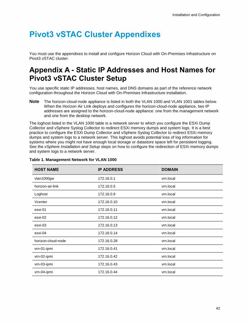
Appendix A - Static IP Addresses and Host Names for Pivot3 vSTAC Cluster Setup
You use specific static IP addresses, host names, and DNS domains as part of the reference network configuration throughout the Horizon Cloud with On-Premises Infrastructure installation.
Note The horizon-cloud-node appliance is listed in both the VLAN 1000 and VLAN 1001 tables below. When the Horizon Air Link deploys and configures the horizon-cloud-node appliance, two IP addresses are assigned to the horizon-cloud-node appliance: one from the management network and one from the desktop network.
The loghost listed in the VLAN 1000 table is a network server to which you configure the ESXi Dump Collector and vSphere Syslog Collector to redirect ESXi memory dumps and system logs. It is a best practice to configure the ESXi Dump Collector and vSphere Syslog Collector to redirect ESXi memory dumps and system logs to a network server. This loghost avoids potential loss of log information for systems where you might not have enough local storage or datastore space left for persistent logging. See the vSphere Installation and Setup steps on how to configure the redirection of ESXi memory dumps and system logs to a network server.
Table 1. Management Network for VLAN 1000
HOST NAME IP ADDRESS DOMAIN
vlan1000gw 172.16.0.1 vrn.local
horizon-air-link 172.16.0.5 vrn.local
Loghost 172.16.0.9 vrn.local
Vcenter 172.16.0.10 vrn.local
esxi-01 172.16.0.11 vrn.local
esxi-02 172.16.0.12 vrn.local
esxi-03 172.16.0.13 vrn.local
esxi-04 172.16.0.14 vrn.local
horizon-cloud-node 172.16.0.28 vrn.local
vrn-01-ipmi 172.16.0.41 vrn.local
vrn-02-ipmi 172.16.0.42 vrn.local
vrn-03-ipmi 172.16.0.43 vrn.local
vrn-04-ipmi 172.16.0.44 vrn.local
Installation and Configuration
43
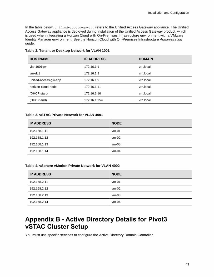
In the table below, unified-access-gw-app refers to the Unified Access Gateway appliance. The Unified
Access Gateway appliance is deployed during installation of the Unified Access Gateway product, which is used when integrating a Horizon Cloud with On-Premises Infrastructure environment with a VMware Identity Manager environment. See the Horizon Cloud with On-Premises Infrastructure Administration guide.
Table 2. Tenant or Desktop Network for VLAN 1001
HOSTNAME IP ADDRESS DOMAIN
vlan1001gw 172.16.1.1 vrn.local
vrn-dc1 172.16.1.3 vrn.local
unified-access-gw-app 172.16.1.9 vrn.local
horizon-cloud-node 172.16.1.11 vrn.local
(DHCP start) 172.16.1.16 vrn.local
(DHCP end) 172.16.1.254 vrn.local
Table 3. vSTAC Private Network for VLAN 4001
IP ADDRESS NODE
192.168.1.11 vrn-01
192.168.1.12 vrn-02
192.168.1.13 vrn-03
192.168.1.14 vrn-04
Table 4. vSphere vMotion Private Network for VLAN 4002
IP ADDRESS NODE
192.168.2.11 vrn-01
192.168.2.12 vrn-02
192.168.2.13 vrn-03
192.168.2.14 vrn-04
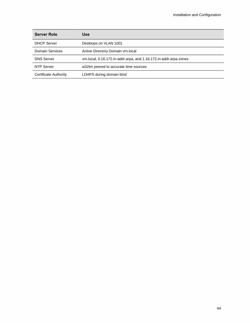
Appendix B - Active Directory Details for Pivot3 vSTAC Cluster Setup
You must use specific services to configure the Active Directory Domain Controller.
Installation and Configuration
44
Server Role Use
DHCP Server Desktops on VLAN 1001
Domain Services Active Directory Domain vrn.local
DNS Server vrn.local, 0.16.172.in-addr.arpa, and 1.16.172.in-addr.arpa zones
NTP Server w32tm peered to accurate time sources
Certificate Authority LDAPS during domain bind


