Please read carefully prior to installation and maintenance 6 720 813 423 – 2014/10 EN-US For heating engineers Installation and maintenance instructions Oil and gas-fired boilers Logano G215 US C
Transcript
Please read carefully prior to installation and maintenance
6 720 813 423 – 2014/10 EN-US For heating engineers
Installation and maintenanceinstructions
Oil and gas-fired boilersLogano G215 US
C
Table of Content
2 Installation and maintenance instructions Logano G215 US oil/gas-fired boilers • Issue 2014/10
We reserve the right to make any changes due to technical modifications.
We reserve the right to make any changes due to technical modifications.
Installation and maintenance instructions Logano G215 US oil/gas-fired boilers • Issue 2014/10
1 Safety Considerations
1.1 With respect to this manual
This installation and maintenance manual containsimportant information for the safe and correctinstallation, initial start-up and maintenance of thisboiler.
The oil and gas fired boiler Logano G215 is generallyreferred to below as a boiler.
The installation and maintenance manual is provided fortechnicians who have been trained and have experiencein working with heating systems and oil and gas firedinstallations.
1.2 Application Purpose
The boiler can only be used for hot water space heatingand water heating for single and multi family homes.
Please note the details on the rating plate and thespecifications ( Chapter 3, page 8) to ensure thecorrect use of this equipment.
1.3 Guideline of Notice
The following symbols are used in this manual:
Cross references
Cross references to a specific section or anotherdocument are identified with an arrow .
1.4 Please observe these notes
Observe all local codes and standards during installationand operation:
– Local building code regulations regardinginstallation, combustion air supply and flue gassystems as well as connection to a chimney.
– Electrical code requirements for connection to thepower supply.
– The technical rules of the gas supply companyregarding the connection of a gas burner to the gassystem.
– Regulations and standards regarding safetyequipment of the heating system.
1.4.1 If you notice a smell of gas
1.4.2 Installation tips
WARNING!
DANGER TO LIFE
Identifies possible risks that may lead toserious injury or death if appropriate care isnot taken.
CAUTION!
DANGER OF INJURY/SYSTEM DAMAGE
Identifies a possible dangerous situationthat can lead to mild to moderate personalinjury or physical damage.
NOTICE
Tip for optimum use of equipment andadjustment as well as useful information.
NOTICE
Use only original Buderus components.Losses caused by the use of parts notsupplied by Buderus are excluded fromthe Buderus warranty.
WARNING!
DANGER TO LIFE
through the explosion of volatile gases.If you can smell gas there is a risk ofexplosion.
Extinguish all open flames. Do notsmoke. Do not use lighters.
Prevent sparks.Do not operate electrical switches,including telephones, plugs or door-bells.
Close the main gas shut-off valve.
Open windows and doors.
Warn all occupants, but do not usedoorbells.
Call gas company from outside thebuilding.
If you hear gas escaping, immediatelyleave the building, prevent others fromentering and notify the police and firebrigade from outside the building.
WARNING!
DANGER TO LIFE
through the explosion of volatile gases.
Work on gas components must becarried out by qualified and authorizedpersonnel only.
Safety Considerations1
6 Installation and maintenance instructions Logano G215 US oil/gas-fired boilers • Issue 2014/10
We reserve the right to make any changes due to technical modifications.
1.4.3 Tips for the boiler room
1.5 Tools, materials and equipment
Installation and maintenance of the boiler requires thestandard tools used in heating, oil, gas and waterinstallations.
The following may also prove useful:
– Sack trolley with strap or Buderus boiler trolley
– Wood supports
– Cleaning brushes and/or chemical cleaning agent forwet cleaning
If the boiler is delivered in sections, you will also requirethe following:
– Compression tool 1.2 if the boiler is supplied insections ( compression tool documentation)
– Flat board
– Cleaning agent
– Installation kit (accessory)
– Steel hammer and wooden or rubber mallet
– Half-round bastard file
– Screwdriver (Philips and slotted head)
– Flat chisel
– Wrench SW 19, 36, 13, 19, 18, 24, 27 and Allen keySW19
– Support wedge, flat iron
– Cleaning rags and cloth
– Fine emery cloth
– Wire brush
– 3-in-1 oil
– Cleaning agent, ruler, chalk, straight edge
– Blanking flange with vent facility (for pressure test)
1.6 Disposal
Dispose of packaging in an environmentallyresponsible manner.
Dispose of all heating system components that haveto be replaced at an authorized disposal site.
WARNING!
DANGER TO LIFE
from electric shock.
Only qualified electricians arepermitted to carry out electrical work.
Before you open a device: Shut offelectrical supply and secure againstaccidental activation.
Please observe all installationinstructions.
WARNING!
DANGER TO LIFE
through poisoning.Insufficient ventilation can result inhazardous discharge of flue gas whenoperation requires air from the room.
Never block off or obstruct air ducts andvents or reduce their size.
The boiler must not be operated until theobstruction has been removed.
Inform the system user in writing of thefault and associated danger.
WARNING!
RISK OF FIRE
through flammable materials or liquids.
Never store flammable materials orliquids in the immediate vicinity of theboiler.
WARNING!
DANGER TO LIFE
through toxic flue gases.
Make sure that mechanical ventilationequipment, such as kitchen extractionhoods, clothes dryers or fans, does notextract combustion air from the boilerroom.
WARNING!
DANGER TO LIFE
through toxic flue gases.
Make sure that the boiler is onlyoperated with chimneys or exhaustsystems that allow the requiredpressure during operation.
Product Description 2
7
We reserve the right to make any changes due to technical modifications.
Installation and maintenance instructions Logano G215 US oil/gas-fired boilers • Issue 2014/10
2 Product Description
This boiler is a low temperature boiler for oil or gascombustion with modulating boiler water temperaturecontrol.
The boiler consists of:
– Logamatic control panel (optional)
– Boiler jacket
– Boiler block with insulation
The control device monitors and controls all electricalboiler components.
The standard boiler is equipped with an AquaSmartTM orHydroStat control.
The boiler casing prevents heat losses and acts as anoise insulator.
The boiler block transfers the heat generated by theburner to the heating water. The insulation preventsenergy losses.
Suitable burner
Install a suitable oil or a gas burner on the boiler. Notethe boiler specifications when selecting the burner( Chapter 3.1, page 8).
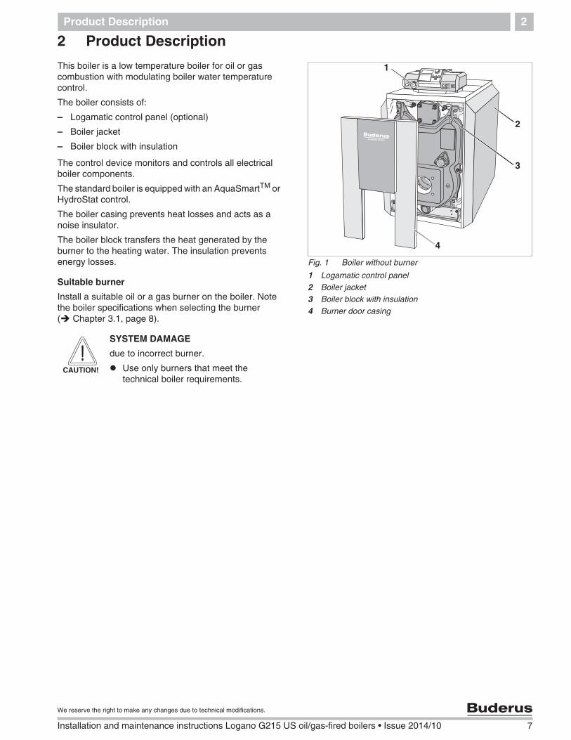
Fig. 1 Boiler without burner
1 Logamatic control panel2 Boiler jacket3 Boiler block with insulation4 Burner door casing
1
2
3
4
CAUTION!
SYSTEM DAMAGE
due to incorrect burner.
Use only burners that meet thetechnical boiler requirements.
8 Installation and maintenance instructions Logano G215 US oil/gas-fired boilers • Issue 2014/10
We reserve the right to make any changes due to technical modifications.
Technical information3
3 Technical information
3.1 Technical data for boiler without burner
Select a suitable burner for this boiler using theinformation in this chapter.
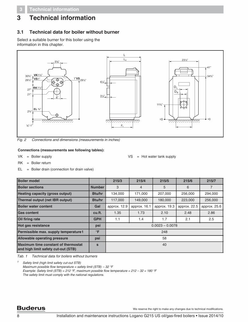
Fig. 2 Connections and dimensions (measurements in inches)
Boiler water content Gal approx. 12.9 approx. 16.1 approx. 19.3 approx. 22.5 approx. 25.6
Gas content cu.ft. 1.35 1.73 2.10 2.48 2.86
Oil firing rate GPH 1.1 1.4 1.7 2.1 2.5
Hot gas resistance psi 0.0023 – 0.0078
Permissible max. supply temperature1 °F 248
Allowable operating pressure psi 58
Maximum time constant of thermostatand high limit safety cut-out (STB)
s 40
Tab. 1 Technical data for boilers without burners
1 Safety limit (high limit safety cut-out STB)Maximum possible flow temperature = safety limit (STB) – 32 °FExample: Safety limit (STB) = 212 °F, maximum possible flow temperature = 212 – 32 = 180 °FThe safety limit must comply with the national regulations.
Technical information 3
9
We reserve the right to make any changes due to technical modifications.
Installation and maintenance instructions Logano G215 US oil/gas-fired boilers • Issue 2014/10
3.2 Operating conditions
If the operating conditions listed on the following pageare maintained, long and trouble-free operation of theboiler can be expected. Some details relate only tooperation with Logamatic control panels from Buderus.
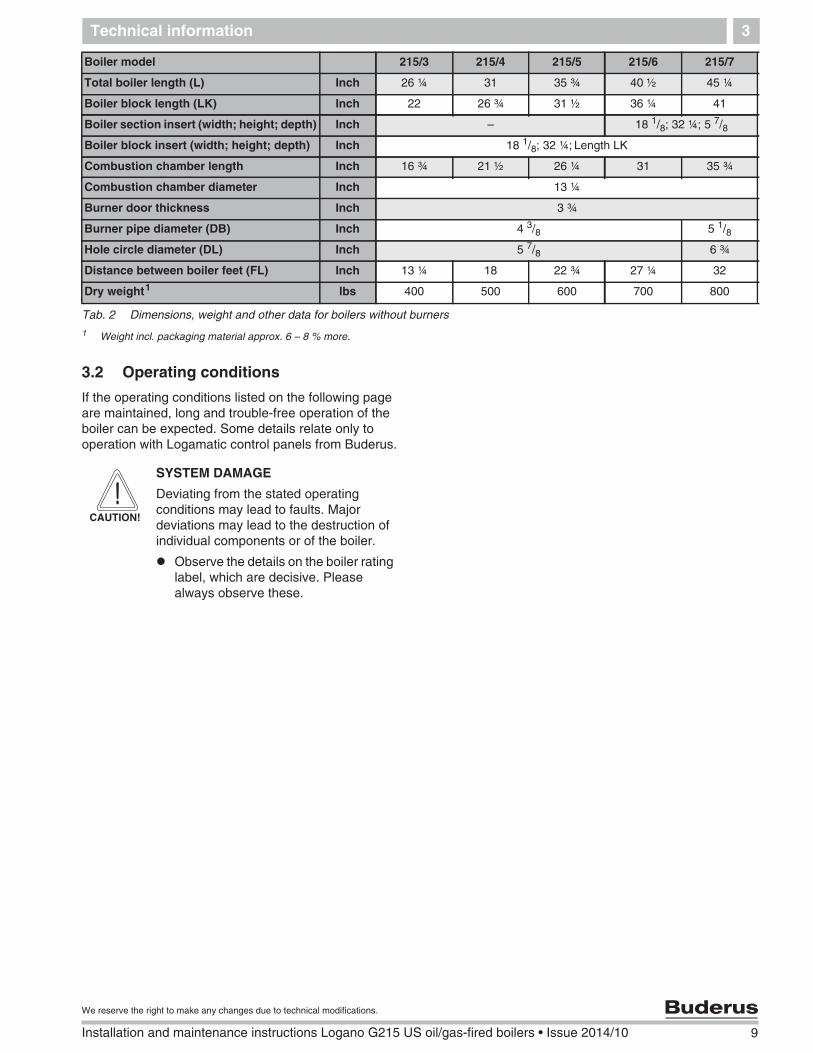
Boiler model 215/3 215/4 215/5 215/6 215/7
Total boiler length (L) Inch 26 ¼ 31 35 ¾ 40 ½ 45 ¼
Boiler block length (LK) Inch 22 26 ¾ 31 ½ 36 ¼ 41
Combustion chamber length Inch 16 ¾ 21 ½ 26 ¼ 31 35 ¾
Combustion chamber diameter Inch 13 ¼
Burner door thickness Inch 3 ¾
Burner pipe diameter (DB) Inch 4 3/8 5 1/8
Hole circle diameter (DL) Inch 5 7/8 6 ¾
Distance between boiler feet (FL) Inch 13 ¼ 18 22 ¾ 27 ¼ 32
Dry weight1 lbs 400 500 600 700 800
Tab. 2 Dimensions, weight and other data for boilers without burners
1 Weight incl. packaging material approx. 6 – 8 % more.
CAUTION!
SYSTEM DAMAGE
Deviating from the stated operatingconditions may lead to faults. Majordeviations may lead to the destruction ofindividual components or of the boiler.
Observe the details on the boiler ratinglabel, which are decisive. Pleasealways observe these.
10 Installation and maintenance instructions Logano G215 US oil/gas-fired boilers • Issue 2014/10
We reserve the right to make any changes due to technical modifications.
Technical information3
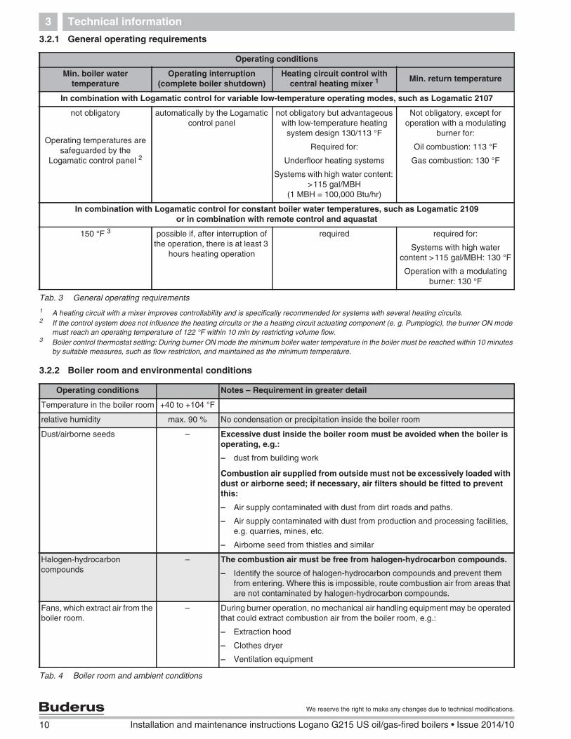
3.2.1 General operating requirements
3.2.2 Boiler room and environmental conditions
Operating conditions
Min. boiler watertemperature
Operating interruption(complete boiler shutdown)
Heating circuit control withcentral heating mixer 1 Min. return temperature
In combination with Logamatic control for variable low-temperature operating modes, such as Logamatic 2107
not obligatory
Operating temperatures aresafeguarded by the
Logamatic control panel 2
automatically by the Logamaticcontrol panel
not obligatory but advantageouswith low-temperature heating
system design 130/113 °F
Required for:
Underfloor heating systems
Systems with high water content:>115 gal/MBH
(1 MBH = 100,000 Btu/hr)
Not obligatory, except foroperation with a modulating
burner for:
Oil combustion: 113 °F
Gas combustion: 130 °F
In combination with Logamatic control for constant boiler water temperatures, such as Logamatic 2109or in combination with remote control and aquastat
150 °F 3 possible if, after interruption ofthe operation, there is at least 3
hours heating operation
required required for:
Systems with high watercontent >115 gal/MBH: 130 °F
Operation with a modulatingburner: 130 °F
Tab. 3 General operating requirements
1 A heating circuit with a mixer improves controllability and is specifically recommended for systems with several heating circuits.2 If the control system does not influence the heating circuits or the a heating circuit actuating component (e. g. Pumplogic), the burner ON mode
must reach an operating temperature of 122 °F within 10 min by restricting volume flow.3 Boiler control thermostat setting: During burner ON mode the minimum boiler water temperature in the boiler must be reached within 10 minutes
by suitable measures, such as flow restriction, and maintained as the minimum temperature.
Operating conditions Notes – Requirement in greater detail
Temperature in the boiler room +40 to +104 °F
relative humidity max. 90 % No condensation or precipitation inside the boiler room
Dust/airborne seeds – Excessive dust inside the boiler room must be avoided when the boiler isoperating, e.g.:
– dust from building work
Combustion air supplied from outside must not be excessively loaded withdust or airborne seed; if necessary, air filters should be fitted to preventthis:
– Air supply contaminated with dust from dirt roads and paths.
– Air supply contaminated with dust from production and processing facilities,e.g. quarries, mines, etc.
– Airborne seed from thistles and similar
Halogen-hydrocarboncompounds
– The combustion air must be free from halogen-hydrocarbon compounds.
– Identify the source of halogen-hydrocarbon compounds and prevent themfrom entering. Where this is impossible, route combustion air from areas thatare not contaminated by halogen-hydrocarbon compounds.
Fans, which extract air from theboiler room.
– During burner operation, no mechanical air handling equipment may be operatedthat could extract combustion air from the boiler room, e.g.:
– Extraction hood
– Clothes dryer
– Ventilation equipment
Tab. 4 Boiler room and ambient conditions
Technical information 3
11
We reserve the right to make any changes due to technical modifications.
Installation and maintenance instructions Logano G215 US oil/gas-fired boilers • Issue 2014/10
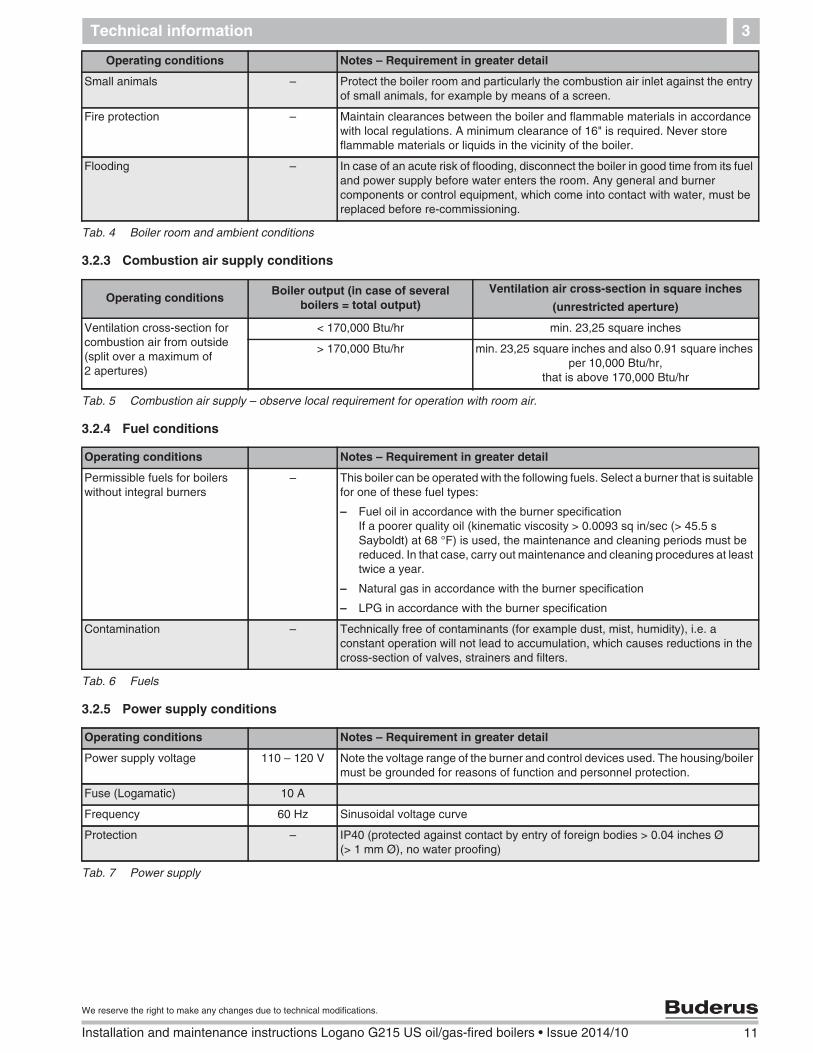
3.2.3 Combustion air supply conditions
3.2.4 Fuel conditions
3.2.5 Power supply conditions
Small animals – Protect the boiler room and particularly the combustion air inlet against the entryof small animals, for example by means of a screen.
Fire protection – Maintain clearances between the boiler and flammable materials in accordancewith local regulations. A minimum clearance of 16" is required. Never storeflammable materials or liquids in the vicinity of the boiler.
Flooding – In case of an acute risk of flooding, disconnect the boiler in good time from its fueland power supply before water enters the room. Any general and burnercomponents or control equipment, which come into contact with water, must bereplaced before re-commissioning.
Operating conditions Notes – Requirement in greater detail
Tab. 4 Boiler room and ambient conditions
Operating conditionsBoiler output (in case of several
boilers = total output)Ventilation air cross-section in square inches
(unrestricted aperture)
Ventilation cross-section forcombustion air from outside(split over a maximum of2 apertures)
< 170,000 Btu/hr min. 23,25 square inches
> 170,000 Btu/hr min. 23,25 square inches and also 0.91 square inchesper 10,000 Btu/hr,
that is above 170,000 Btu/hr
Tab. 5 Combustion air supply – observe local requirement for operation with room air.
Operating conditions Notes – Requirement in greater detail
Permissible fuels for boilerswithout integral burners
– This boiler can be operated with the following fuels. Select a burner that is suitablefor one of these fuel types:
– Fuel oil in accordance with the burner specificationIf a poorer quality oil (kinematic viscosity > 0.0093 sq in/sec (> 45.5 sSayboldt) at 68 °F) is used, the maintenance and cleaning periods must bereduced. In that case, carry out maintenance and cleaning procedures at leasttwice a year.
– Natural gas in accordance with the burner specification
– LPG in accordance with the burner specification
Contamination – Technically free of contaminants (for example dust, mist, humidity), i.e. aconstant operation will not lead to accumulation, which causes reductions in thecross-section of valves, strainers and filters.
Tab. 6 Fuels
Operating conditions Notes – Requirement in greater detail
Power supply voltage 110 – 120 V Note the voltage range of the burner and control devices used. The housing/boilermust be grounded for reasons of function and personnel protection.
Fuse (Logamatic) 10 A
Frequency 60 Hz Sinusoidal voltage curve
Protection – IP40 (protected against contact by entry of foreign bodies > 0.04 inches Ø(> 1 mm Ø), no water proofing)
Tab. 7 Power supply
12 Installation and maintenance instructions Logano G215 US oil/gas-fired boilers • Issue 2014/10
We reserve the right to make any changes due to technical modifications.
Technical information3
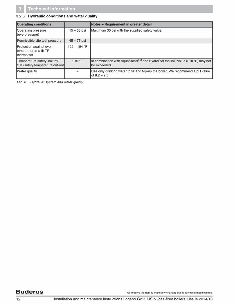
3.2.6 Hydraulic conditions and water quality
Operating conditions Notes – Requirement in greater detail
Operating pressure(overpressure)
15 – 58 psi Maximum 30 psi with the supplied safety valve.
Permissible site test pressure 45 – 75 psi
Protection against over-temperatures with TRthermostat
122 – 194 °F
Temperature safety limit bySTB safety temperature cut-out
210 °F In combination with AquaSmartTM and HydroStat the limit value (210 °F) may notbe exceeded.
Water quality – Use only drinking water to fill and top-up the boiler. We recommend a pH valueof 8.2 – 9.5.
Tab. 8 Hydraulic system and water quality
Packaging and Components 4
13
We reserve the right to make any changes due to technical modifications.
Installation and maintenance instructions Logano G215 US oil/gas-fired boilers • Issue 2014/10
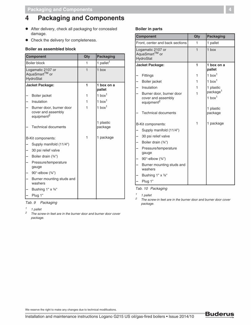
4 Packaging and Components
After delivery, check all packaging for concealeddamage.
Check the delivery for completeness.
Boiler as assembled block
Boiler in parts
Component Qty Packaging
Boiler block 1 1 pallet1
Logamatic 2107 orAquaSmartTM orHydroStat
1 1 box
Jacket Package:
– Boiler jacket
– Insulation
– Burner door, burner doorcover and assemblyequipment2
– Technical documents
B-Kit components:
– Supply manifold (11/4")
– 30 psi relief valve
– Boiler drain (¾")
– Pressure/temperaturegauge
– 90°-elbow (¾")
– Burner mounting studs andwashers
– Bushing 1" x ¾"
– Plug 1"
1
1
1
1
1
1 box on apallet
1 box1
1 box1
1 box1
1 plasticpackage
1 package
Tab. 9 Packaging
1 1 pallet2 The screw-in feet are in the burner door and burner door cover
package.
Component Qty Packaging
Front, center and back sections 1 1 pallet
Logamatic 2107 orAquaSmartTM orHydroStat
1 1 box
Jacket Package:
– Fittings
– Boiler jacket
– Insulation
– Burner door, burner doorcover and assemblyequipment2
– Technical documents
B-Kit components:
– Supply manifold (11/4")
– 30 psi relief valve
– Boiler drain (¾")
– Pressure/temperaturegauge
– 90°-elbow (¾")
– Burner mounting studs andwashers
– Bushing 1" x ¾"
– Plug 1"
1
1
1
1
1
1
1 box on apallet
1 box1
1 box1
1 plasticpackage1
1 box1
1 plasticpackage
1 package
Tab. 10 Packaging
1 1 pallet2 The screw-in feet are in the burner door and burner door cover
package.
14 Installation and maintenance instructions Logano G215 US oil/gas-fired boilers • Issue 2014/10
We reserve the right to make any changes due to technical modifications.
Moving the boiler5
5 Moving the boiler
This chapter details how to move the boiler safely.
CAUTION!
SYSTEM DAMAGE
due to bumps.
Please observe the handling directionson the packaging to protectcomponents from bumps and roughtreatment.
NOTICE
Protect boiler connections from damageand dirt if the boiler is not installedimmediately.
NOTICE
Dispose of packaging in anenvironmentally responsible manner.
CAUTION!
RISK OF INJURY
by not securing the boiler adequatelyduring transport.
Use only suitable means fortransportation, e.g. a trolley with strap,a stair or step trolley.
Secure the load against falling.
Placing the Boiler 6
15
We reserve the right to make any changes due to technical modifications.
Installation and maintenance instructions Logano G215 US oil/gas-fired boilers • Issue 2014/10
6 Placing the Boiler
This chapter details how to install and place the boiler inthe boiler room.
6.1 Clearances
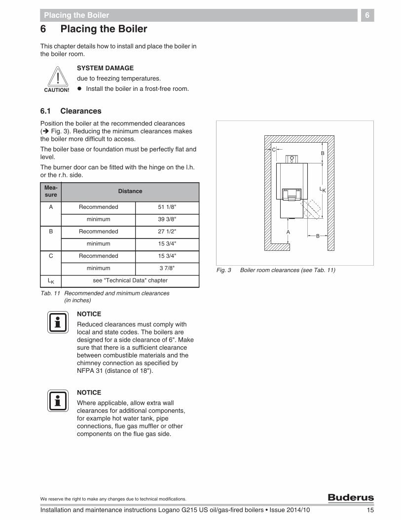
Position the boiler at the recommended clearances( Fig. 3). Reducing the minimum clearances makesthe boiler more difficult to access.
The boiler base or foundation must be perfectly flat andlevel.
The burner door can be fitted with the hinge on the l.h.or the r.h. side.
CAUTION!
SYSTEM DAMAGE
due to freezing temperatures.
Install the boiler in a frost-free room.
Fig. 3 Boiler room clearances (see Tab. 11)
Mea-sure
Distance
A Recommended 51 1/8"
minimum 39 3/8"
B Recommended 27 1/2"
minimum 15 3/4"
C Recommended 15 3/4"
minimum 3 7/8"
LK see "Technical Data" chapter
Tab. 11 Recommended and minimum clearances(in inches)
NOTICE
Reduced clearances must comply withlocal and state codes. The boilers aredesigned for a side clearance of 6". Makesure that there is a sufficient clearancebetween combustible materials and thechimney connection as specified byNFPA 31 (distance of 18").
NOTICE
Where applicable, allow extra wallclearances for additional components,for example hot water tank, pipeconnections, flue gas muffler or othercomponents on the flue gas side.
16 Installation and maintenance instructions Logano G215 US oil/gas-fired boilers • Issue 2014/10
We reserve the right to make any changes due to technical modifications.
Boiler block assembly7
7 Boiler block assembly
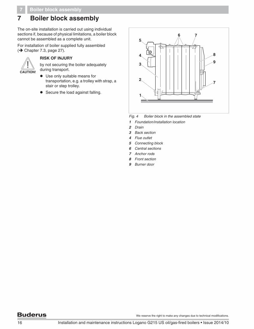
The on-site installation is carried out using individualsections if, because of physical limitations, a boiler blockcannot be assembled as a complete unit.
For installation of boiler supplied fully assembled( Chapter 7.3, page 27).
Fig. 4 Boiler block in the assembled state
1 Foundation/installation location2 Drain3 Back section4 Flue outlet5 Connecting block6 Central sections7 Anchor rods8 Front section9 Burner door
1
3
4
6 7
8
5
9
27
CAUTION!
RISK OF INJURY
by not securing the boiler adequatelyduring transport.
Use only suitable means fortransportation, e.g. a trolley with strap, astair or step trolley.
Secure the load against falling.
Boiler block assembly 7
17
We reserve the right to make any changes due to technical modifications.
Installation and maintenance instructions Logano G215 US oil/gas-fired boilers • Issue 2014/10
7.1 Assembly when delivered in sections
Assemble all boiler sections in accordance with thefollowing instructions and diagrams.
7.1.1 Preparing boiler sections
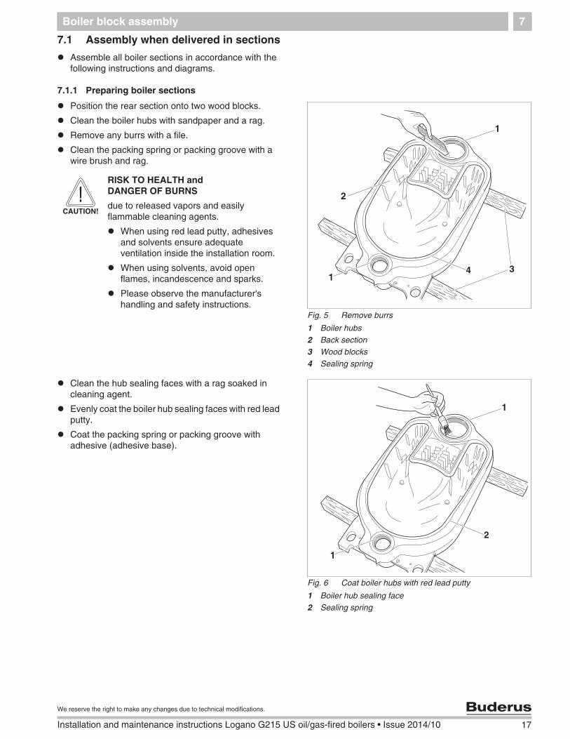
Position the rear section onto two wood blocks.
Clean the boiler hubs with sandpaper and a rag.
Remove any burrs with a file.
Clean the packing spring or packing groove with awire brush and rag.
Clean the hub sealing faces with a rag soaked incleaning agent.
Evenly coat the boiler hub sealing faces with red leadputty.
Coat the packing spring or packing groove withadhesive (adhesive base).
Fig. 5 Remove burrs
1 Boiler hubs2 Back section3 Wood blocks4 Sealing spring
31
2
1
4
CAUTION!
RISK TO HEALTH andDANGER OF BURNS
due to released vapors and easilyflammable cleaning agents.
When using red lead putty, adhesivesand solvents ensure adequateventilation inside the installation room.
When using solvents, avoid openflames, incandescence and sparks.
Please observe the manufacturer'shandling and safety instructions.
Fig. 6 Coat boiler hubs with red lead putty
1 Boiler hub sealing face2 Sealing spring
1
1
2
18 Installation and maintenance instructions Logano G215 US oil/gas-fired boilers • Issue 2014/10
We reserve the right to make any changes due to technical modifications.
Boiler block assembly7
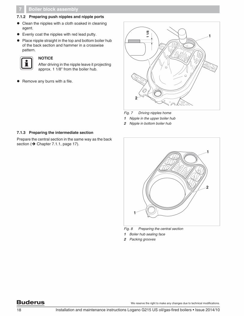
7.1.2 Preparing push nipples and nipple ports
Clean the nipples with a cloth soaked in cleaningagent.
Evenly coat the nipples with red lead putty.
Place nipple straight in the top and bottom boiler hubof the back section and hammer in a crosswisepattern.
Remove any burrs with a file.
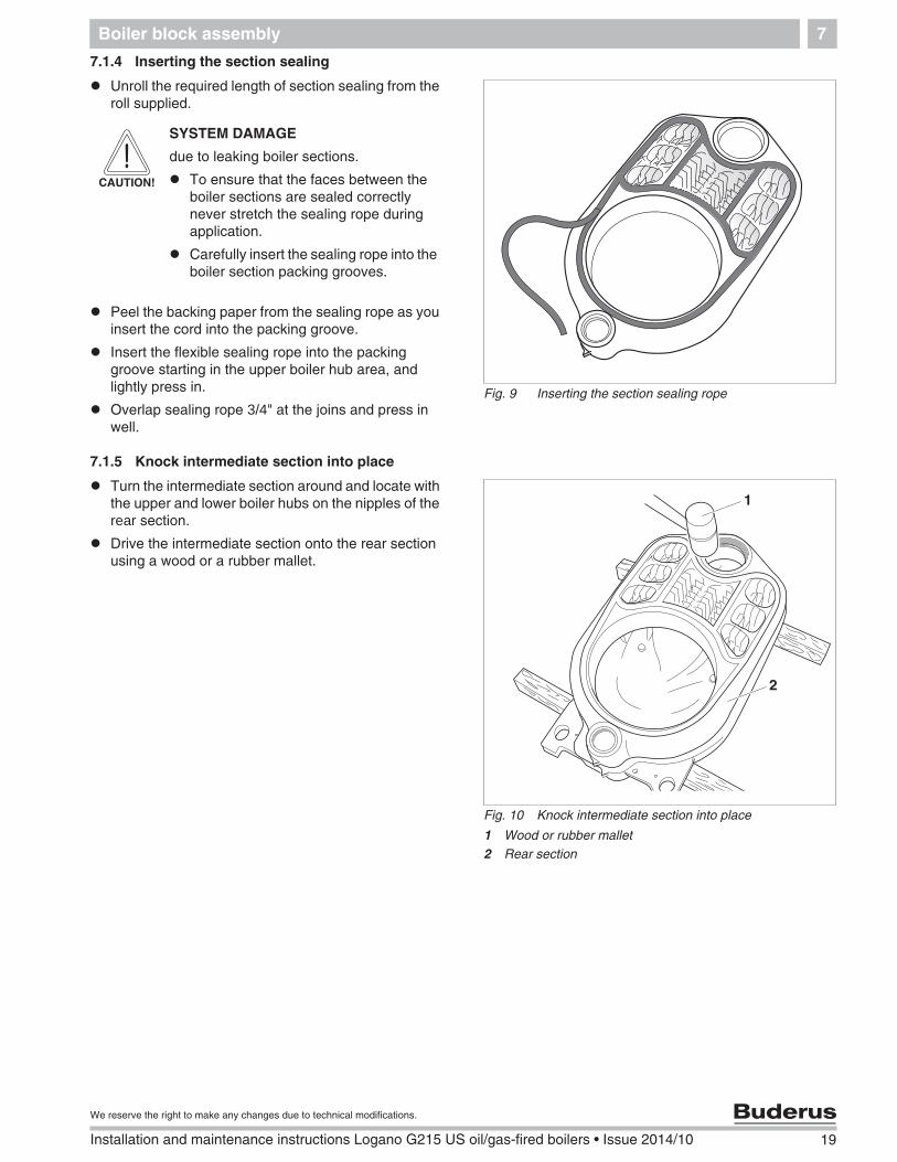
7.1.3 Preparing the intermediate section
Prepare the central section in the same way as the backsection ( Chapter 7.1.1, page 17).
Fig. 7 Driving nipples home
1 Nipple in the upper boiler hub2 Nipple in bottom boiler hub
��
2
111/
8
NOTICE
After driving in the nipple leave it projectingapprox. 1 1/8" from the boiler hub.
Fig. 8 Preparing the central section
1 Boiler hub sealing face2 Packing grooves
1
1
2
Boiler block assembly 7
19
We reserve the right to make any changes due to technical modifications.
Installation and maintenance instructions Logano G215 US oil/gas-fired boilers • Issue 2014/10
7.1.4 Inserting the section sealing
Unroll the required length of section sealing from theroll supplied.
Peel the backing paper from the sealing rope as youinsert the cord into the packing groove.
Insert the flexible sealing rope into the packinggroove starting in the upper boiler hub area, andlightly press in.
Overlap sealing rope 3/4" at the joins and press inwell.
7.1.5 Knock intermediate section into place
Turn the intermediate section around and locate withthe upper and lower boiler hubs on the nipples of therear section.
Drive the intermediate section onto the rear sectionusing a wood or a rubber mallet.
Fig. 9 Inserting the section sealing rope
CAUTION!
SYSTEM DAMAGE
due to leaking boiler sections.
To ensure that the faces between theboiler sections are sealed correctlynever stretch the sealing rope duringapplication.
Carefully insert the sealing rope into theboiler section packing grooves.
Fig. 10 Knock intermediate section into place
1 Wood or rubber mallet2 Rear section
1
2
20 Installation and maintenance instructions Logano G215 US oil/gas-fired boilers • Issue 2014/10
We reserve the right to make any changes due to technical modifications.
Boiler block assembly7
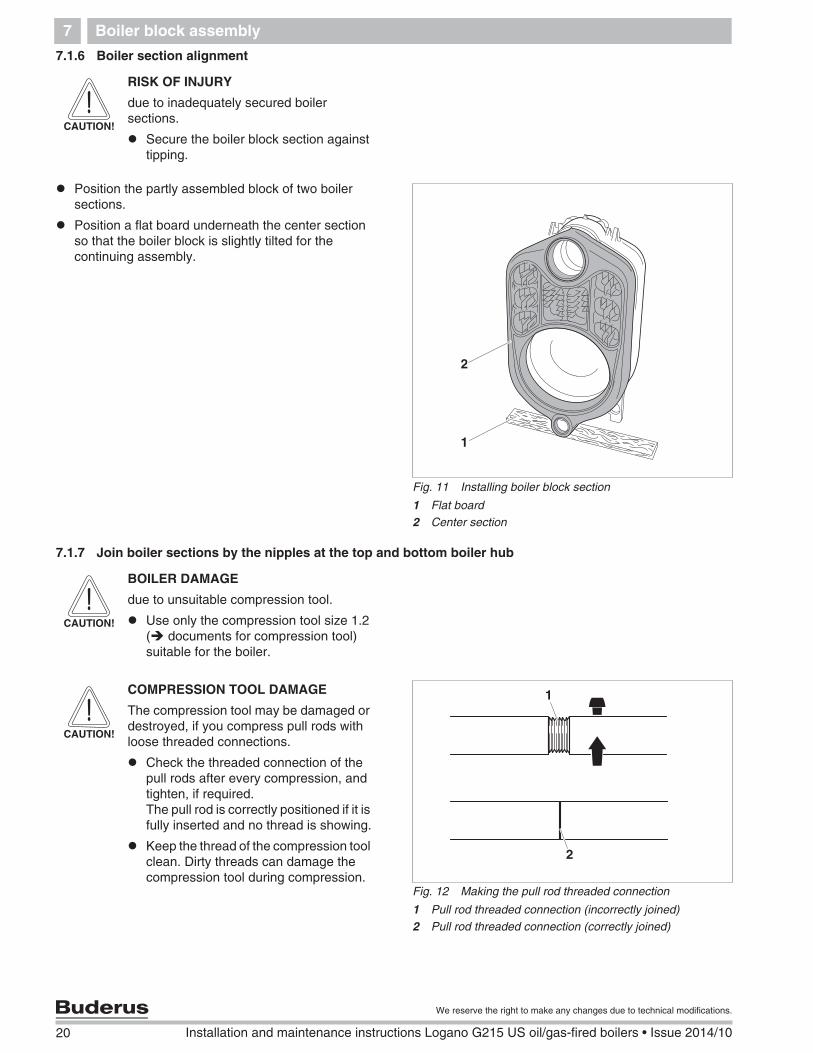
7.1.6 Boiler section alignment
Position the partly assembled block of two boilersections.
Position a flat board underneath the center sectionso that the boiler block is slightly tilted for thecontinuing assembly.
7.1.7 Join boiler sections by the nipples at the top and bottom boiler hub
CAUTION!
RISK OF INJURY
due to inadequately secured boilersections.
Secure the boiler block section againsttipping.
Fig. 11 Installing boiler block section
1 Flat board2 Center section
1
2
CAUTION!
BOILER DAMAGE
due to unsuitable compression tool.
Use only the compression tool size 1.2( documents for compression tool)suitable for the boiler.
Fig. 12 Making the pull rod threaded connection
1 Pull rod threaded connection (incorrectly joined)2 Pull rod threaded connection (correctly joined)
1
2
CAUTION!
COMPRESSION TOOL DAMAGE
The compression tool may be damaged ordestroyed, if you compress pull rods withloose threaded connections.
Check the threaded connection of thepull rods after every compression, andtighten, if required.The pull rod is correctly positioned if it isfully inserted and no thread is showing.
Keep the thread of the compression toolclean. Dirty threads can damage thecompression tool during compression.
Boiler block assembly 7
21
We reserve the right to make any changes due to technical modifications.
Installation and maintenance instructions Logano G215 US oil/gas-fired boilers • Issue 2014/10
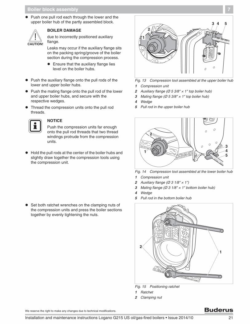
Push one pull rod each through the lower and theupper boiler hub of the partly assembled block.
Push the auxiliary flange onto the pull rods of thelower and upper boiler hubs.
Push the mating flange onto the pull rod of the lowerand upper boiler hubs, and secure with therespective wedges.
Thread the compression units onto the pull rodthreads.
Hold the pull rods at the center of the boiler hubs andslightly draw together the compression tools usingthe compression unit.
Set both ratchet wrenches on the clamping nuts ofthe compression units and press the boiler sectionstogether by evenly tightening the nuts.
Fig. 13 Compression tool assembled at the upper boiler hub
1 Compression unit2 Auxiliary flange (Ø 5 3/8" × 1" top boiler hub)3 Mating flange (Ø 5 3/8" × 1" top boiler hub)4 Wedge5 Pull rod in the upper boiler hub
1
243 5
CAUTION!
BOILER DAMAGE
due to incorrectly positioned auxiliaryflange.
Leaks may occur if the auxiliary flange sitson the packing spring/groove of the boilersection during the compression process.
Ensure that the auxiliary flange lieslevel on the boiler hubs.
Fig. 14 Compression tool assembled at the lower boiler hub
1 Compression unit2 Auxiliary flange (Ø 3 1/8" × 1")3 Mating flange (Ø 3 1/8" × 1" bottom boiler hub)4 Wedge5 Pull rod in the bottom boiler hub
1
2
345
NOTICE
Push the compression units far enoughonto the pull rod threads that two threadwindings protrude from the compressionunits.
Fig. 15 Positioning ratchet
1 Ratchet2 Clamping nut
12
22 Installation and maintenance instructions Logano G215 US oil/gas-fired boilers • Issue 2014/10
We reserve the right to make any changes due to technical modifications.
Boiler block assembly7
Release and remove the compression tool.
Hammer the nipples into the partly assembled boilerblock ( Chapter 7.1.2, page 18).
Prepare all other intermediate sections as describedabove and join them at the nipples.
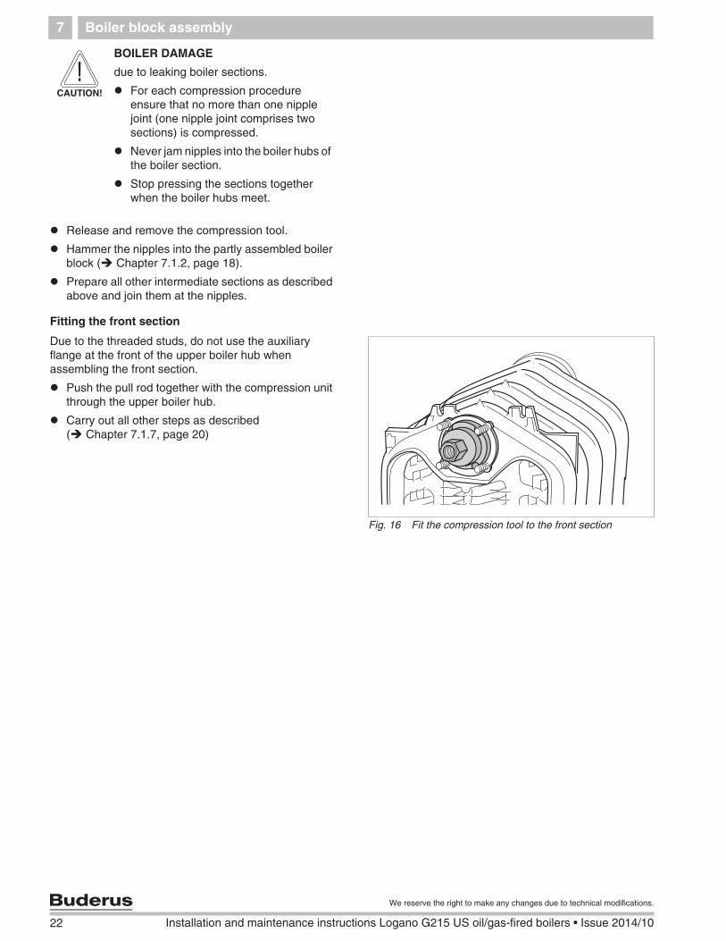
Fitting the front section
Due to the threaded studs, do not use the auxiliaryflange at the front of the upper boiler hub whenassembling the front section.
Push the pull rod together with the compression unitthrough the upper boiler hub.
Carry out all other steps as described( Chapter 7.1.7, page 20)
CAUTION!
BOILER DAMAGE
due to leaking boiler sections.
For each compression procedureensure that no more than one nipplejoint (one nipple joint comprises twosections) is compressed.
Never jam nipples into the boiler hubs ofthe boiler section.
Stop pressing the sections togetherwhen the boiler hubs meet.
Fig. 16 Fit the compression tool to the front section
Boiler block assembly 7
23
We reserve the right to make any changes due to technical modifications.
Installation and maintenance instructions Logano G215 US oil/gas-fired boilers • Issue 2014/10
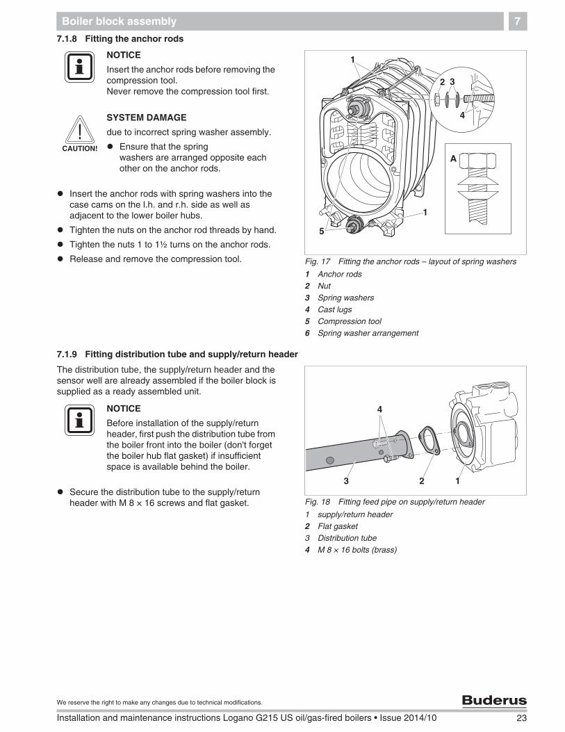
7.1.8 Fitting the anchor rods
Insert the anchor rods with spring washers into thecase cams on the l.h. and r.h. side as well asadjacent to the lower boiler hubs.
Tighten the nuts on the anchor rod threads by hand.
Tighten the nuts 1 to 1½ turns on the anchor rods.
Release and remove the compression tool.
7.1.9 Fitting distribution tube and supply/return header
The distribution tube, the supply/return header and thesensor well are already assembled if the boiler block issupplied as a ready assembled unit.
Secure the distribution tube to the supply/returnheader with M 8 × 16 screws and flat gasket.
Fig. 17 Fitting the anchor rods – layout of spring washers
1 Anchor rods2 Nut3 Spring washers4 Cast lugs5 Compression tool6 Spring washer arrangement
1
1
2 3
5
4
A
NOTICE
Insert the anchor rods before removing thecompression tool.Never remove the compression tool first.
CAUTION!
SYSTEM DAMAGE
due to incorrect spring washer assembly.
Ensure that the springwashers are arranged opposite eachother on the anchor rods.
Fig. 18 Fitting feed pipe on supply/return header
1 supply/return header2 Flat gasket3 Distribution tube4 M 8 × 16 bolts (brass)
123
4NOTICE
Before installation of the supply/returnheader, first push the distribution tube fromthe boiler front into the boiler (don't forgetthe boiler hub flat gasket) if insufficientspace is available behind the boiler.
24 Installation and maintenance instructions Logano G215 US oil/gas-fired boilers • Issue 2014/10
We reserve the right to make any changes due to technical modifications.
Boiler block assembly7
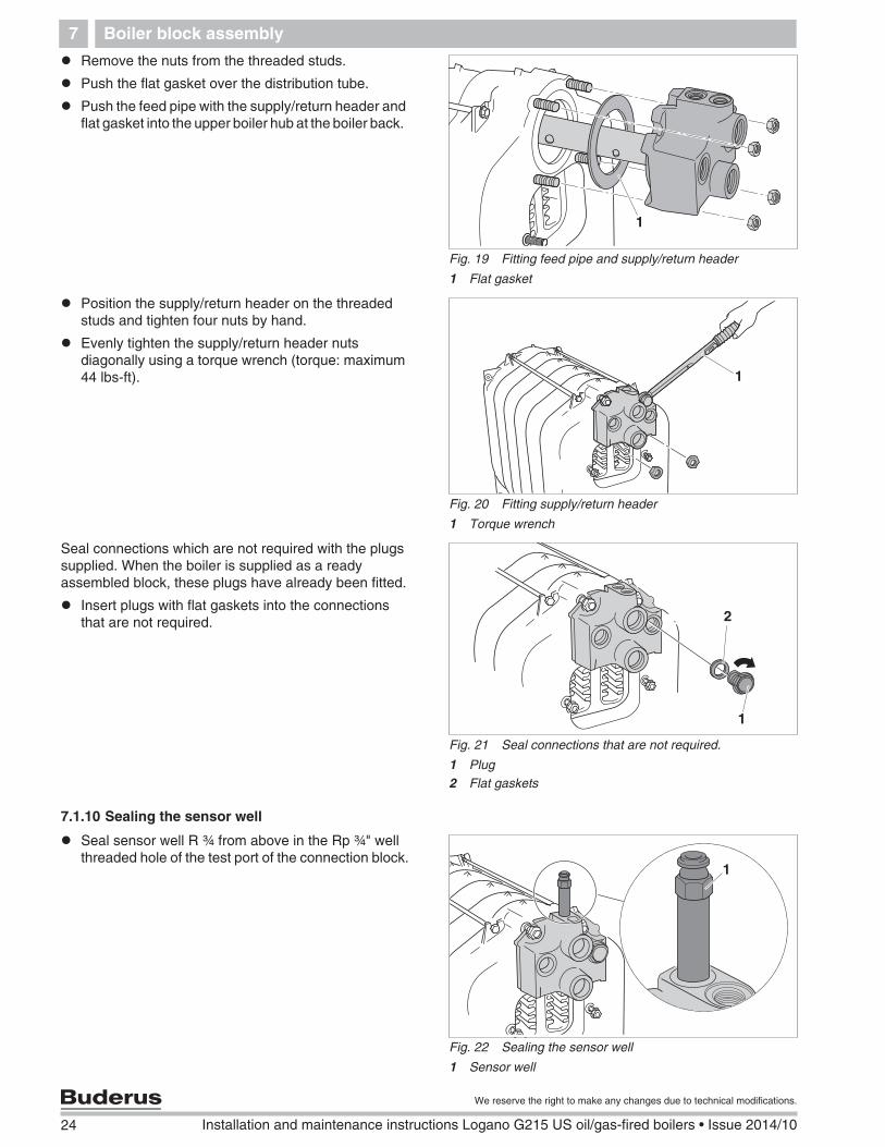
Remove the nuts from the threaded studs.
Push the flat gasket over the distribution tube.
Push the feed pipe with the supply/return header andflat gasket into the upper boiler hub at the boiler back.
Position the supply/return header on the threadedstuds and tighten four nuts by hand.
Evenly tighten the supply/return header nutsdiagonally using a torque wrench (torque: maximum44 lbs-ft).
Seal connections which are not required with the plugssupplied. When the boiler is supplied as a readyassembled block, these plugs have already been fitted.
Insert plugs with flat gaskets into the connectionsthat are not required.
7.1.10 Sealing the sensor well
Seal sensor well R ¾ from above in the Rp ¾" wellthreaded hole of the test port of the connection block.
Fig. 19 Fitting feed pipe and supply/return header
1 Flat gasket
1
Fig. 20 Fitting supply/return header
1 Torque wrench
1
Fig. 21 Seal connections that are not required.
1 Plug2 Flat gaskets
1
2
Fig. 22 Sealing the sensor well
1 Sensor well
1
Boiler block assembly 7
25
We reserve the right to make any changes due to technical modifications.
Installation and maintenance instructions Logano G215 US oil/gas-fired boilers • Issue 2014/10
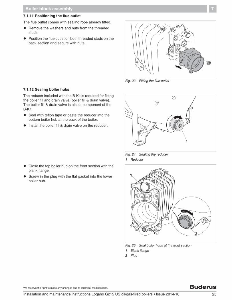
7.1.11 Positioning the flue outlet
The flue outlet comes with sealing rope already fitted.
Remove the washers and nuts from the threadedstuds.
Position the flue outlet on both threaded studs on theback section and secure with nuts.
7.1.12 Sealing boiler hubs
The reducer included with the B-Kit is required for fittingthe boiler fill and drain valve (boiler fill & drain valve).The boiler fill & drain valve is also a component of theB-Kit.
Seal with teflon tape or paste the reducer into thebottom boiler hub at the back of the boiler.
Install the boiler fill & drain valve on the reducer.
Close the top boiler hub on the front section with theblank flange.
Screw in the plug with the flat gasket into the lowerboiler hub.
Fig. 23 Fitting the flue outlet
Fig. 24 Sealing the reducer
1 Reducer
1
Fig. 25 Seal boiler hubs at the front section
1 Blank flange2 Plug
1
2
26 Installation and maintenance instructions Logano G215 US oil/gas-fired boilers • Issue 2014/10
We reserve the right to make any changes due to technical modifications.
Boiler block assembly7
7.2 Check for leaks
Conduct a leak test of the boiler block only when theboiler was delivered disassembled.
7.2.1 Preparing for a leak test
Close all boiler hubs ( Chapter 7.1.12, page 25).
Close front and back connections (fit vent to theRp ¾ connection block ( Fig. 22).
7.2.2 Leak test
Carry out the leak test with a test pressure of 84 psi (inaccordance with the requirements of the EuropeanPressure Vessel Directive).
Slowly fill the boiler block via the boiler fill & drainvalve. Vent at the highest point of the system, untilwater flows out of the air vent valve.
Hub joints leaking?
If a hub joint is leaking, first drain the water throughthe fill & drain valve.
Remove the water pipes.
Remove the distribution tube.
Release and remove the anchor rods.
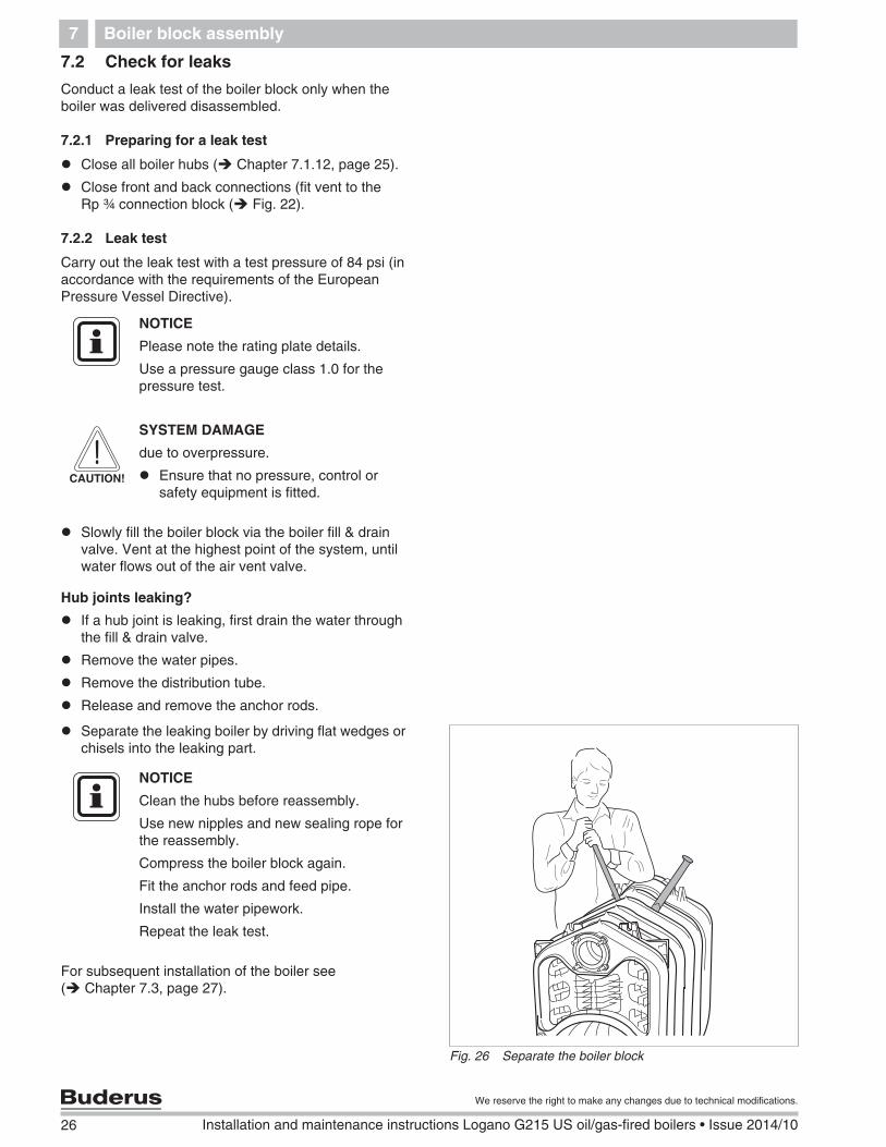
Separate the leaking boiler by driving flat wedges orchisels into the leaking part.
For subsequent installation of the boiler see( Chapter 7.3, page 27).
NOTICE
Please note the rating plate details.
Use a pressure gauge class 1.0 for thepressure test.
CAUTION!
SYSTEM DAMAGE
due to overpressure.
Ensure that no pressure, control orsafety equipment is fitted.
Fig. 26 Separate the boiler block
NOTICE
Clean the hubs before reassembly.
Use new nipples and new sealing rope forthe reassembly.
Compress the boiler block again.
Fit the anchor rods and feed pipe.
Install the water pipework.
Repeat the leak test.
Boiler block assembly 7
27
We reserve the right to make any changes due to technical modifications.
Installation and maintenance instructions Logano G215 US oil/gas-fired boilers • Issue 2014/10
7.3 Installation when boiler is supplied assembled
A leak test of the boiler block is carried out at the factorywhen the boiler is supplied assembled.
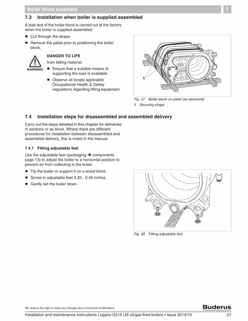
Cut through the straps.
Remove the pallet prior to positioning the boilerblock.
7.4 Installation steps for disassembled and assembled delivery
Carry out the steps detailed in this chapter for deliveriesin sections or as block. Where there are differentprocedures for installation between disassembled andassembled delivery, this is noted in the manual.
7.4.1 Fitting adjustable feet
Use the adjustable feet (packaging componentspage 13) to adjust the boiler to a horizontal position toprevent air from collecting in the boiler.
Tip the boiler or support it on a wood block.
Screw in adjustable feet 0.20 - 0.40 inches.
Gently set the boiler down.
Fig. 27 Boiler block on pallet (as delivered)
1 Securing straps
1
WARNING!
DANGER TO LIFE
from falling material.
Ensure that a suitable means ofsupporting the load is available.
Observe all locally applicableOccupational Health & Safetyregulations regarding lifting equipment.
Fig. 28 Fitting adjustable feet
28 Installation and maintenance instructions Logano G215 US oil/gas-fired boilers • Issue 2014/10
We reserve the right to make any changes due to technical modifications.
Boiler block assembly7
7.4.2 Insert the flue gas baffle plates
Remove the corrugated cardboard packaging whenthe block is supplied ready assembled.
When the boiler is supplied in sections, remove theflue gas baffle plates from the carton containing thesmall iron fittings.
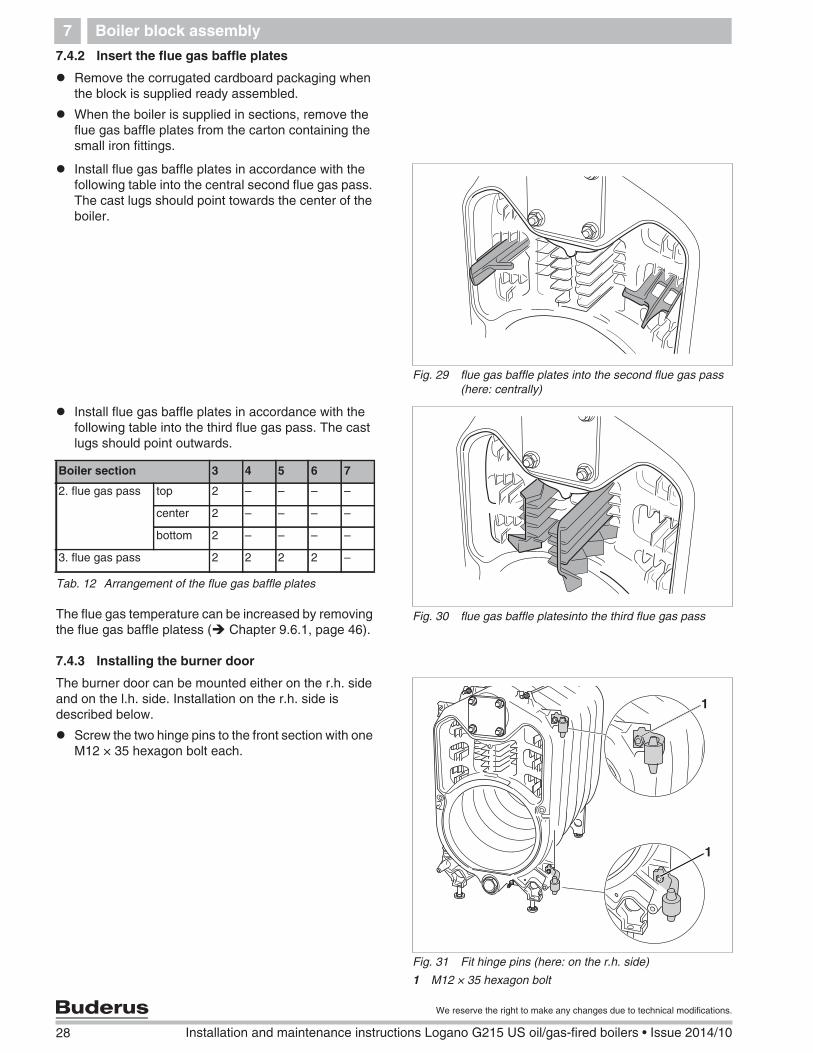
Install flue gas baffle plates in accordance with thefollowing table into the central second flue gas pass.The cast lugs should point towards the center of theboiler.
Install flue gas baffle plates in accordance with thefollowing table into the third flue gas pass. The castlugs should point outwards.
The flue gas temperature can be increased by removingthe flue gas baffle platess ( Chapter 9.6.1, page 46).
7.4.3 Installing the burner door
The burner door can be mounted either on the r.h. sideand on the l.h. side. Installation on the r.h. side isdescribed below.
Screw the two hinge pins to the front section with oneM12 × 35 hexagon bolt each.
Fig. 29 flue gas baffle plates into the second flue gas pass(here: centrally)
Fig. 30 flue gas baffle platesinto the third flue gas pass
Boiler section 3 4 5 6 7
2. flue gas pass top 2 – – – –
center 2 – – – –
bottom 2 – – – –
3. flue gas pass 2 2 2 2 –
Tab. 12 Arrangement of the flue gas baffle plates
Fig. 31 Fit hinge pins (here: on the r.h. side)
1 M12 × 35 hexagon bolt
1
1
Boiler block assembly 7
29
We reserve the right to make any changes due to technical modifications.
Installation and maintenance instructions Logano G215 US oil/gas-fired boilers • Issue 2014/10
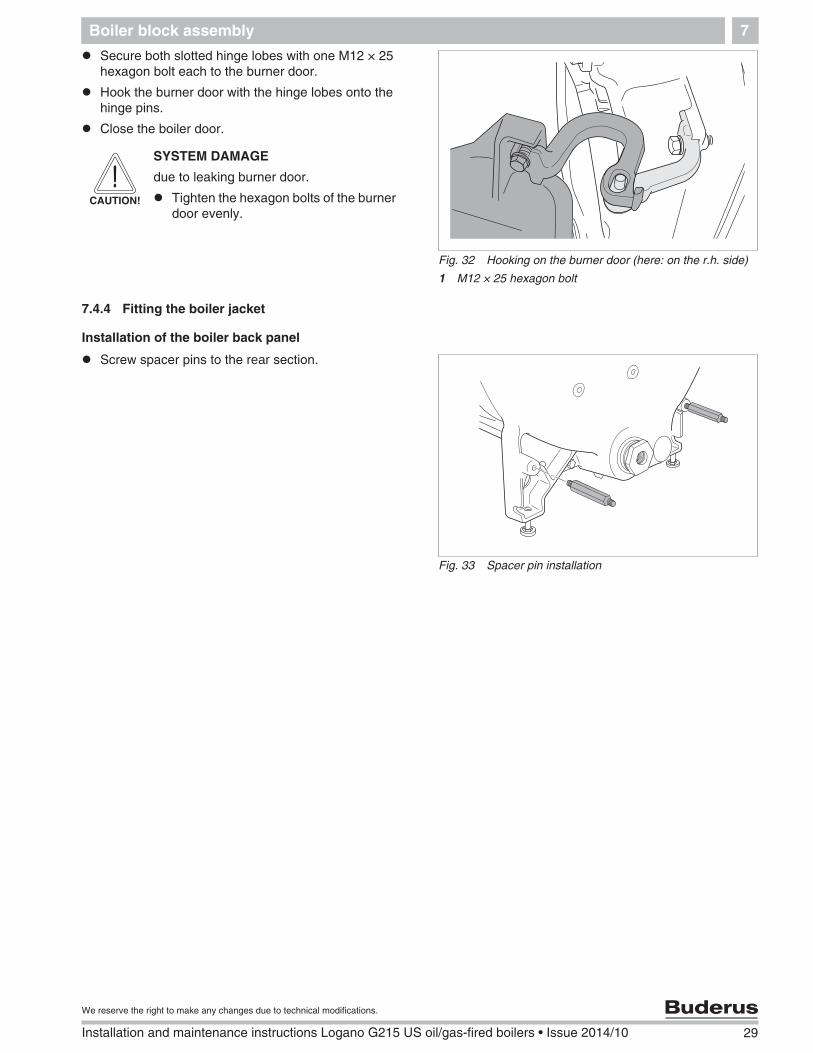
Secure both slotted hinge lobes with one M12 × 25hexagon bolt each to the burner door.
Hook the burner door with the hinge lobes onto thehinge pins.
Close the boiler door.
7.4.4 Fitting the boiler jacket
Installation of the boiler back panel
Screw spacer pins to the rear section.
Fig. 32 Hooking on the burner door (here: on the r.h. side)
1 M12 × 25 hexagon bolt
CAUTION!
SYSTEM DAMAGE
due to leaking burner door.
Tighten the hexagon bolts of the burnerdoor evenly.
Fig. 33 Spacer pin installation
30 Installation and maintenance instructions Logano G215 US oil/gas-fired boilers • Issue 2014/10
We reserve the right to make any changes due to technical modifications.
Boiler block assembly7
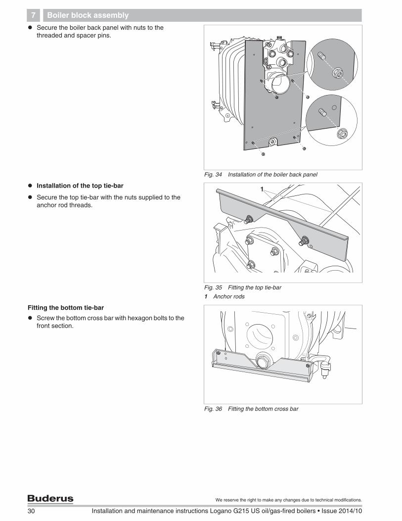
Secure the boiler back panel with nuts to thethreaded and spacer pins.
Installation of the top tie-bar
Secure the top tie-bar with the nuts supplied to theanchor rod threads.
Fitting the bottom tie-bar
Screw the bottom cross bar with hexagon bolts to thefront section.
Fig. 34 Installation of the boiler back panel
Fig. 35 Fitting the top tie-bar
1 Anchor rods
1
Fig. 36 Fitting the bottom cross bar
Boiler block assembly 7
31
We reserve the right to make any changes due to technical modifications.
Installation and maintenance instructions Logano G215 US oil/gas-fired boilers • Issue 2014/10
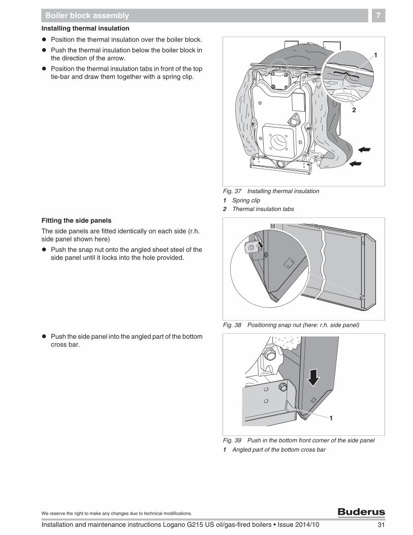
Installing thermal insulation
Position the thermal insulation over the boiler block.
Push the thermal insulation below the boiler block inthe direction of the arrow.
Position the thermal insulation tabs in front of the toptie-bar and draw them together with a spring clip.
Fitting the side panels
The side panels are fitted identically on each side (r.h.side panel shown here)
Push the snap nut onto the angled sheet steel of theside panel until it locks into the hole provided.
Push the side panel into the angled part of the bottomcross bar.
Fig. 37 Installing thermal insulation
1 Spring clip2 Thermal insulation tabs
2
1
Fig. 38 Positioning snap nut (here: r.h. side panel)
Fig. 39 Push in the bottom front corner of the side panel
1 Angled part of the bottom cross bar
1
32 Installation and maintenance instructions Logano G215 US oil/gas-fired boilers • Issue 2014/10
We reserve the right to make any changes due to technical modifications.
Boiler block assembly7
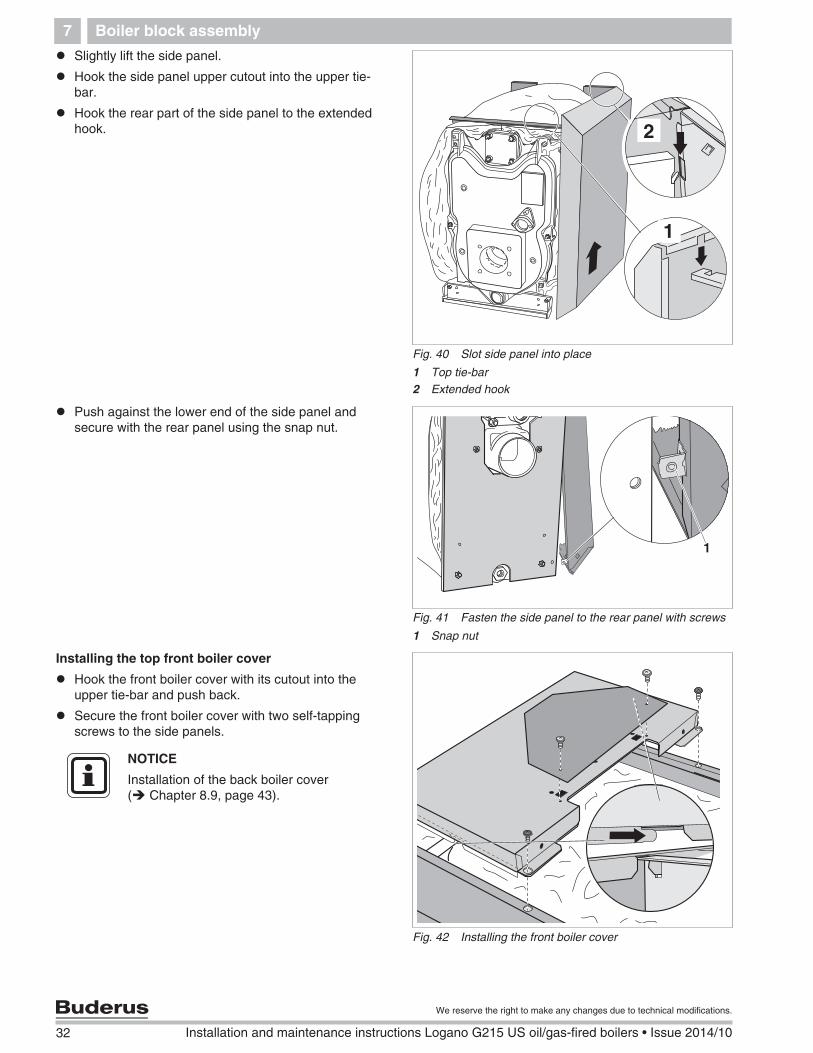
Slightly lift the side panel.
Hook the side panel upper cutout into the upper tie-bar.
Hook the rear part of the side panel to the extendedhook.
Push against the lower end of the side panel andsecure with the rear panel using the snap nut.
Installing the top front boiler cover
Hook the front boiler cover with its cutout into theupper tie-bar and push back.
Secure the front boiler cover with two self-tappingscrews to the side panels.
Fig. 40 Slot side panel into place
1 Top tie-bar2 Extended hook
1
2
Fig. 41 Fasten the side panel to the rear panel with screws
1 Snap nut
1
Fig. 42 Installing the front boiler cover
NOTICE
Installation of the back boiler cover( Chapter 8.9, page 43).
Boiler block assembly 7
33
We reserve the right to make any changes due to technical modifications.
Installation and maintenance instructions Logano G215 US oil/gas-fired boilers • Issue 2014/10
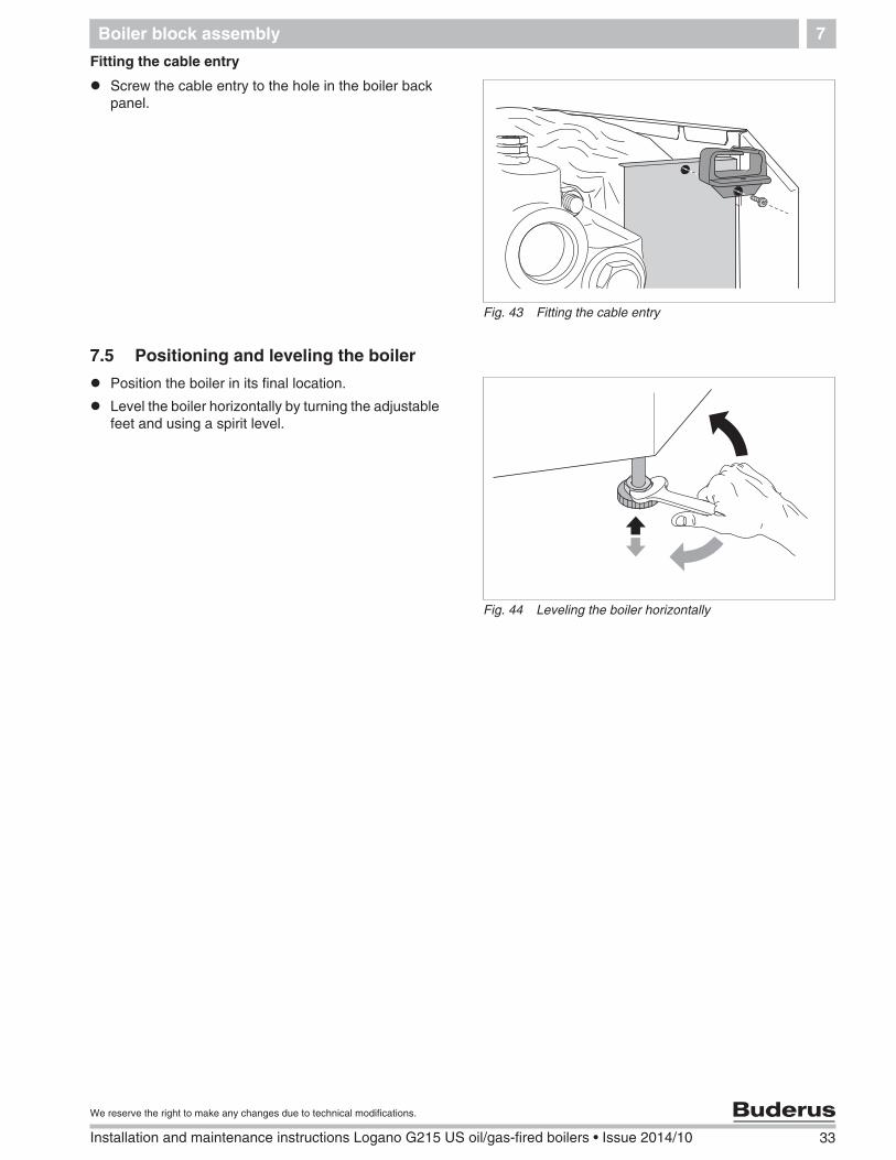
Fitting the cable entry
Screw the cable entry to the hole in the boiler backpanel.
7.5 Positioning and leveling the boiler
Position the boiler in its final location.
Level the boiler horizontally by turning the adjustablefeet and using a spirit level.
Fig. 43 Fitting the cable entry
Fig. 44 Leveling the boiler horizontally
34 Installation and maintenance instructions Logano G215 US oil/gas-fired boilers • Issue 2014/10
We reserve the right to make any changes due to technical modifications.
Boiler installation8
8 Boiler installation
This chapter details how to install your boiler correctly.These details include:
– Flue connection
– Water connections
– Electrical connection
– Burner installation (field installation)
– Fuel connection
8.1 Flue connection
8.1.1 Chimney venting
Connect boiler to vertical chimney with a 6" vent pipe.Use only venting systems that comply with local codesand regulations. If local codes are not available, refer thethe following regulations:
– NFPA 31, Installation of Oil-Burning Equipment,
– NFPA 211, Standard for Chimneys, Fire Places andSolid Fuel Burning Appliances,
– In Canada refer to CSA B139, Installation Code forOil-Burning Equipment,
– NFPA 211 requires chimney to be lined beforeconnecting boiler.
Inspecting and cleaning existing flue
Inspect and clean the old flue before installation of thenew boiler.
Remove blockages and dirt from the chimney.
Clean chimney
Repair or replace faulty flues.
If necessary, repair chimney with mortar and joints.
Down drafts
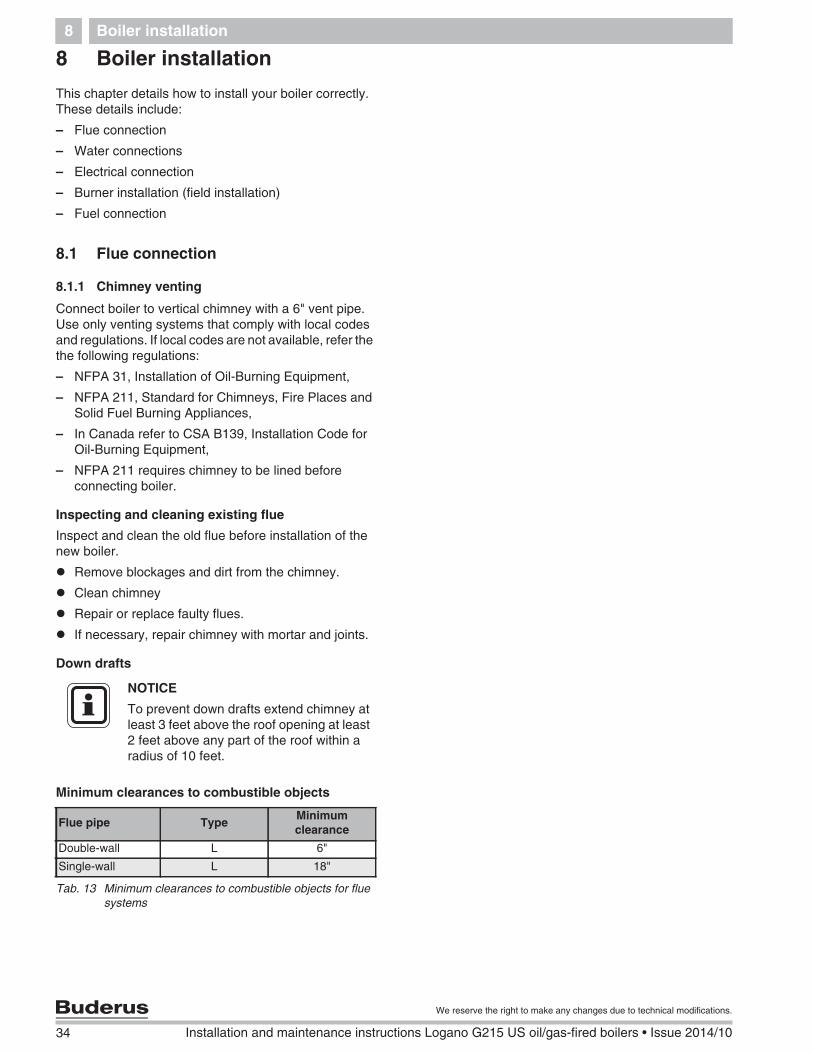
Minimum clearances to combustible objects
NOTICE
To prevent down drafts extend chimney atleast 3 feet above the roof opening at least2 feet above any part of the roof within aradius of 10 feet.
Flue pipe TypeMinimumclearance
Double-wall L 6"
Single-wall L 18"
Tab. 13 Minimum clearances to combustible objects for fluesystems
Boiler installation 8
35
We reserve the right to make any changes due to technical modifications.
Installation and maintenance instructions Logano G215 US oil/gas-fired boilers • Issue 2014/10
Minimum size of chimney
The minimum recommended chimney size is 8" x 8"(6 3/4" x 6 3/4" inside liner) or 6" diameter with aminimum height of 20 feet. Use a 6" flue pipe forconnection to an existing chimney.
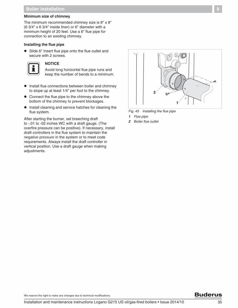
Installing the flue pipe
Slide 6" Insert flue pipe onto the flue outlet andsecure with 2 screws.
Install flue connections between boiler and chimneyto slope up at least 1/4" per foot to the chimney.
Connect the flue pipe to the chimney above thebottom of the chimney to prevent blockages.
Install cleaning and service hatches for cleaning theflue system.
After starting the burner, set breeching draftto -.01 to -02 inches WC with a draft gauge. (Theoverfire pressure can be positive). If necessary, installdraft controllers in the flue system to maintain thenegative pressure in the system or to meet coderequirements. Always install the draft controller invertical position. Use a draft gauge when makingadjustments.
Fig. 45 Installing the flue pipe
1 Flue pipe2 Boiler flue outlet
1
2
NOTICE
Avoid long horizontal flue pipe runs andkeep the number of bends to a minimum.
36 Installation and maintenance instructions Logano G215 US oil/gas-fired boilers • Issue 2014/10
We reserve the right to make any changes due to technical modifications.
Boiler installation8
8.2 Installation of water connections
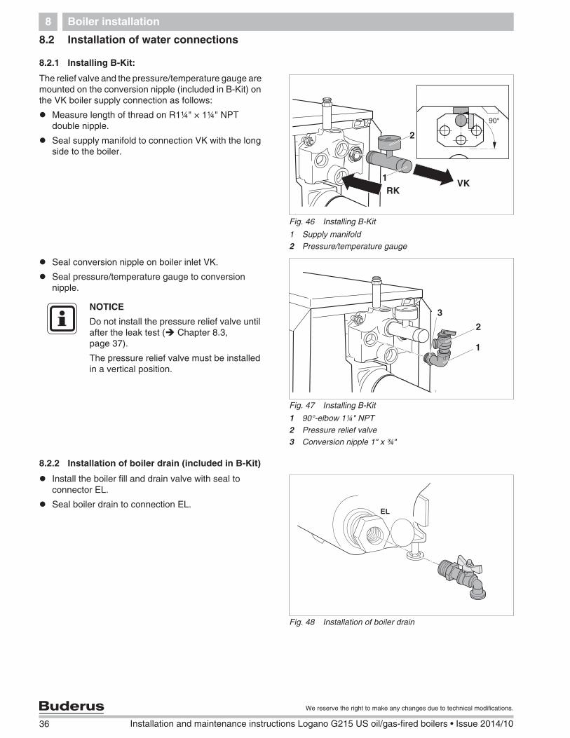
8.2.1 Installing B-Kit:
The relief valve and the pressure/temperature gauge aremounted on the conversion nipple (included in B-Kit) onthe VK boiler supply connection as follows:
Measure length of thread on R1¼" × 1¼" NPTdouble nipple.
Seal supply manifold to connection VK with the longside to the boiler.
Seal conversion nipple on boiler inlet VK.
Seal pressure/temperature gauge to conversionnipple.
8.2.2 Installation of boiler drain (included in B-Kit)
Install the boiler fill and drain valve with seal toconnector EL.
Do not install the pressure relief valve untilafter the leak test ( Chapter 8.3,page 37).
The pressure relief valve must be installedin a vertical position.
Fig. 48 Installation of boiler drain
��
Boiler installation 8
37
We reserve the right to make any changes due to technical modifications.
Installation and maintenance instructions Logano G215 US oil/gas-fired boilers • Issue 2014/10
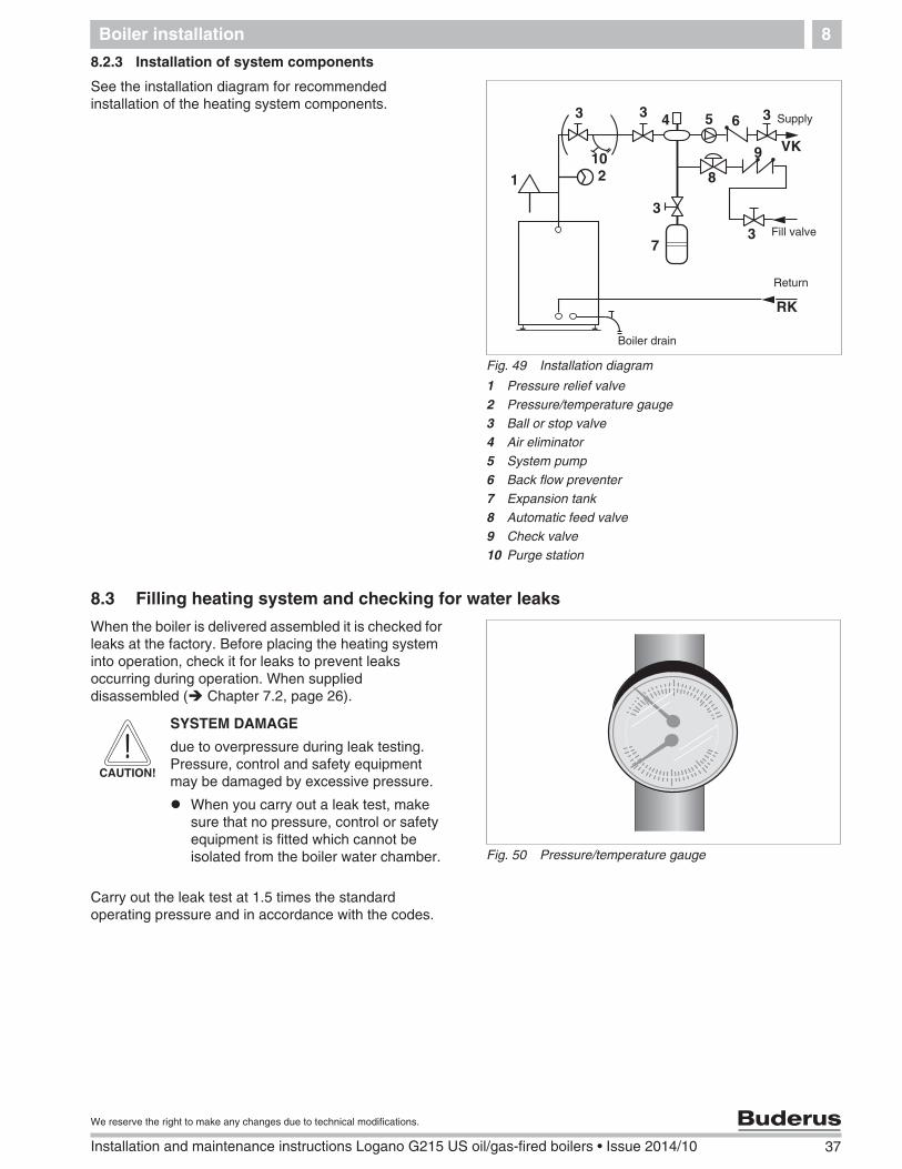
8.2.3 Installation of system components
See the installation diagram for recommendedinstallation of the heating system components.
8.3 Filling heating system and checking for water leaks
When the boiler is delivered assembled it is checked forleaks at the factory. Before placing the heating systeminto operation, check it for leaks to prevent leaksoccurring during operation. When supplieddisassembled ( Chapter 7.2, page 26).
Carry out the leak test at 1.5 times the standardoperating pressure and in accordance with the codes.
Fig. 49 Installation diagram
1 Pressure relief valve2 Pressure/temperature gauge3 Ball or stop valve4 Air eliminator5 System pump6 Back flow preventer7 Expansion tank8 Automatic feed valve9 Check valve10 Purge station
1 2
3 4 5 6 33
7
8
9
3
10
Return
Fill valve
Boiler drain
Supply
VK
RK
3
Fig. 50 Pressure/temperature gauge
CAUTION!
SYSTEM DAMAGE
due to overpressure during leak testing.Pressure, control and safety equipmentmay be damaged by excessive pressure.
When you carry out a leak test, makesure that no pressure, control or safetyequipment is fitted which cannot beisolated from the boiler water chamber.
38 Installation and maintenance instructions Logano G215 US oil/gas-fired boilers • Issue 2014/10
We reserve the right to make any changes due to technical modifications.
Boiler installation8
Seal pressure relief valve connection ( Fig. 47page 36) and all other open connection with blindplugs.
Close the expansion tank from the system by closingthe cap valve.
Open the mixing and shut-off valves on the heatingwater (primary) side.
Connect the hose to the water tap. Attach a hosefilled with water onto the hose connection of theboiler fill & drain valve, fasten with a hose clip andopen the valve.
Slowly fill the boiler with water from the tap.
Open the cap of the automatic air vent by one full turnto allow air to escape.
Slowly fill the heating system. Observe the pressuregauge while filling.
Close the water tap and the boiler fill & drain valveonce the required operating pressure has beenreached.
Check the connections and pipework for soundness.
Bleed the system via the radiator bleed valves.
Top off with water if the pressure drops as a result ofbleeding the system.
Remove the hose from the boiler fill and drain valve.
8.4 Burner installation
Only one burner that complies with the technical data ofthe boiler can be mounted on boilers without integratedburners ( Chapter 3, page 8).
Maximumoperating pressure
Maximum site testpressure
30 psi (with the suppliedpressure relief valve)
45 psi
58 psi (with a differentpressure relief valve)
75 psi
CAUTION!
SYSTEM DAMAGE
due to incorrect burner.
Only use burners which meet thetechnical boiler requirements.
Boiler installation 8
39
We reserve the right to make any changes due to technical modifications.
Installation and maintenance instructions Logano G215 US oil/gas-fired boilers • Issue 2014/10
Screw studs included with the B-Kit to the burnerdoor.
Fit the burner to the hole circle of the burner door.
Install burner with the correct nozzle and settings(air, pump pressure, turbulator settings, flangeposition).
Place the seal on the studs and secure the burnerwith the included nuts.
Follow the manufacturer's direction for installation,fine adjustment and regular maintenanceprocedures.
Wire up the burner (see documentation forburner).
8.5 Providing a fuel supply
Make the fuel connection in accordance with all locallyapplicable regulations. We recommend the installationof a fuel filter.
Visually inspect the fuel pipe and clean or replace, ifnecessary.
Install a shut-off valve into the fuel supply pipe.
Connect the fuel pipe free of stress to the boiler.
Check the fuel line for leaks.
8.6 AquaSmartTM installation
The AquaSmartTM controls the boiler supplytemperature.
For Installation and Operation of the AquaSmartTM
Control and sensor well see the AquaSmartTM
Installation Instructions supplied with the control. Forwiring diagrams of the AquaSmartTM Chapter 12,page 57.
Install AquaSmartTM and sensor well as specified bythe installation manual.
For operating the boiler with AquaSmartTM control seeinstructions supplied with the controller.
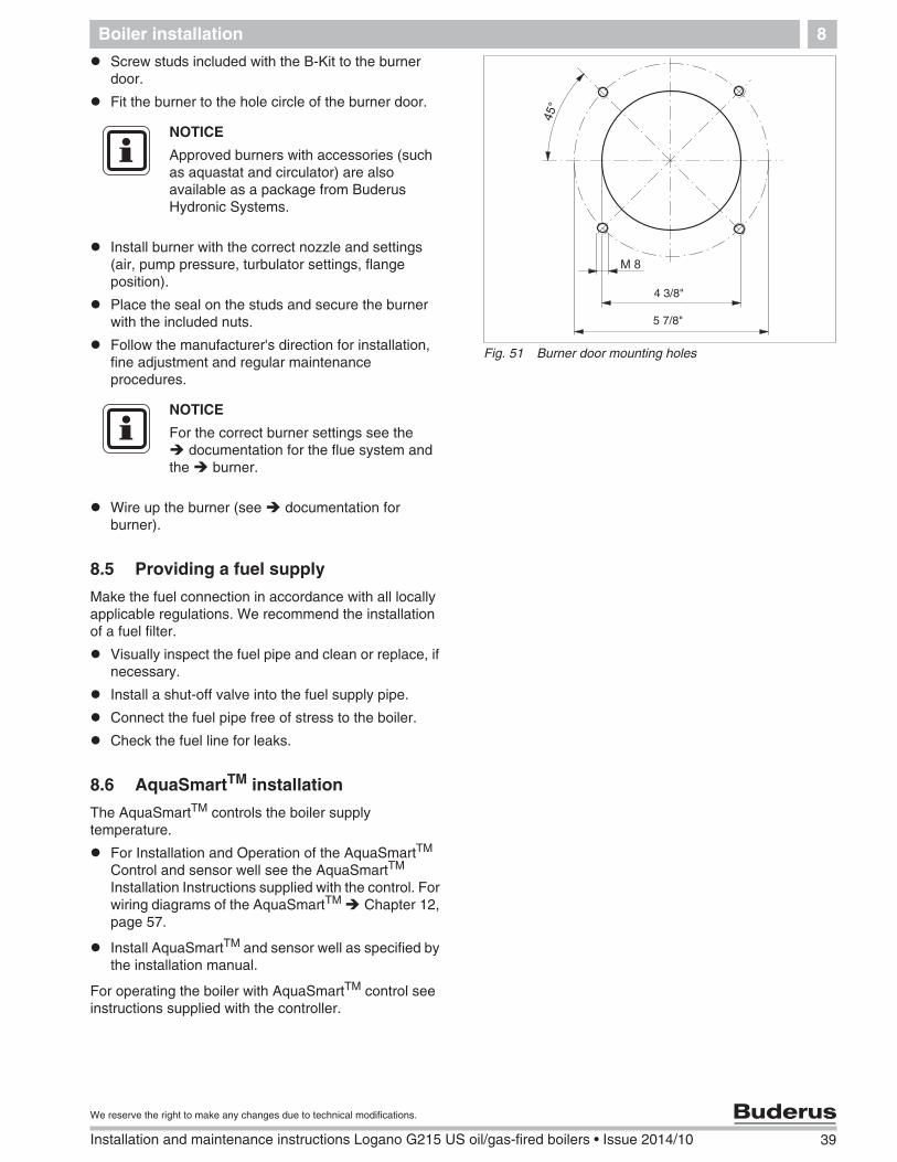
Fig. 51 Burner door mounting holes
4 3/8"
5 7/8"
NOTICE
Approved burners with accessories (suchas aquastat and circulator) are alsoavailable as a package from BuderusHydronic Systems.
NOTICE
For the correct burner settings see thedocumentation for the flue system and
the burner.
40 Installation and maintenance instructions Logano G215 US oil/gas-fired boilers • Issue 2014/10
We reserve the right to make any changes due to technical modifications.
Boiler installation8
8.7 HydroStat installation
The HydroStat controls the boiler supply temperature.
For Installation and Operation of the HydroStatControl and sensor well see the HydroStatInstallation Instructions supplied with the control. Forwiring diagrams of the HydroStat Chapter 12,page 57.
8.8 Electrical connections
This section only applies to boilers using BuderusLogamatic 2107 controls.
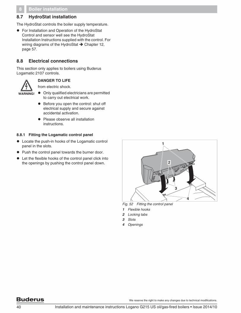
8.8.1 Fitting the Logamatic control panel
Locate the push-in hooks of the Logamatic controlpanel in the slots.
Push the control panel towards the burner door.
Let the flexible hooks of the control panel click intothe openings by pushing the control panel down.
WARNING!
DANGER TO LIFE
from electric shock.
Only qualified electricians are permittedto carry out electrical work.
Before you open the control: shut offelectrical supply and secure againstaccidental activation.
Please observe all installationinstructions.
Fig. 52 Fitting the control panel
1 Flexible hooks2 Locking tabs3 Slots4 Openings
1
4
2
3
Boiler installation 8
41
We reserve the right to make any changes due to technical modifications.
Installation and maintenance instructions Logano G215 US oil/gas-fired boilers • Issue 2014/10
Remove the Logamatic control panel cover. Firstremove the cover screws.
Secure the control panel with self-tapping screws.
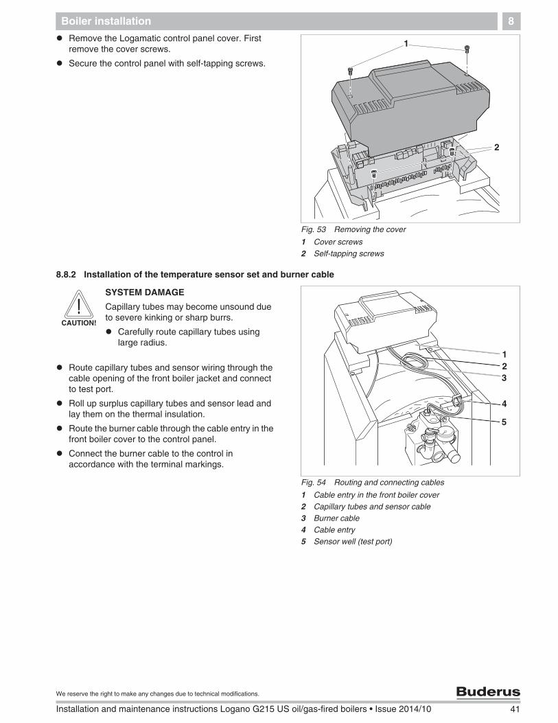
8.8.2 Installation of the temperature sensor set and burner cable
Route capillary tubes and sensor wiring through thecable opening of the front boiler jacket and connectto test port.
Roll up surplus capillary tubes and sensor lead andlay them on the thermal insulation.
Route the burner cable through the cable entry in thefront boiler cover to the control panel.
Connect the burner cable to the control inaccordance with the terminal markings.
Fig. 53 Removing the cover
1 Cover screws2 Self-tapping screws
1
2
Fig. 54 Routing and connecting cables
1 Cable entry in the front boiler cover2 Capillary tubes and sensor cable3 Burner cable4 Cable entry5 Sensor well (test port)
1
3
5
2
4
CAUTION!
SYSTEM DAMAGE
Capillary tubes may become unsound dueto severe kinking or sharp burrs.
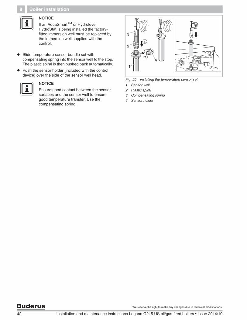
If an AquaSmartTM or HydrolevelHydroStat is being installed the factory-fitted immersion well must be replaced bythe immersion well supplied with thecontrol.
NOTICE
Ensure good contact between the sensorsurfaces and the sensor well to ensuregood temperature transfer. Use thecompensating spring.
Boiler installation 8
43
We reserve the right to make any changes due to technical modifications.
Installation and maintenance instructions Logano G215 US oil/gas-fired boilers • Issue 2014/10
8.8.3 Electrical connections and connection of additional components
Install a permanent electrical power connection inaccordance with local codes.
Route all cables through the cable entries to theLogamatic control panel and connect in accordancewith the wiring diagram.
8.8.4 Strain relief installation
Secure all cable runs with cable ties (included with thecontrol):
Insert the cable ties together with the cable from thetop into the slots of the clamp frame (step 1).
Push the cable tie down (step 2).
Push against the tie (step 3).
Flick the toggle up (step 4).
8.9 Jacket panel installation
Locate and secure the Logamatic control panel topdevice cover.
Fit the rear boiler cover.
WARNING!
RISK OF FIRE
Hot components may damage electricalwiring.
Ensure that all wiring is routed in theducts provided or on the boilerinsulation.
Fig. 56 Securing cables with cable ties
Fig. 57 Install the back boiler cover
1 Control panel cover2 Back boiler cover
21
44 Installation and maintenance instructions Logano G215 US oil/gas-fired boilers • Issue 2014/10
We reserve the right to make any changes due to technical modifications.
Placing the boiler in operation9
9 Placing the boiler in operation
This chapter describes the initial start-up procedureregardless of the installed control device.
Complete the start-up protocol during this process( Chapter 9.9, page 48).
Further information on boiler room layout andclearances, combustion air requirements and ventingsystems and boiler operational requirements can befound in Chapter 3.2, page 9.
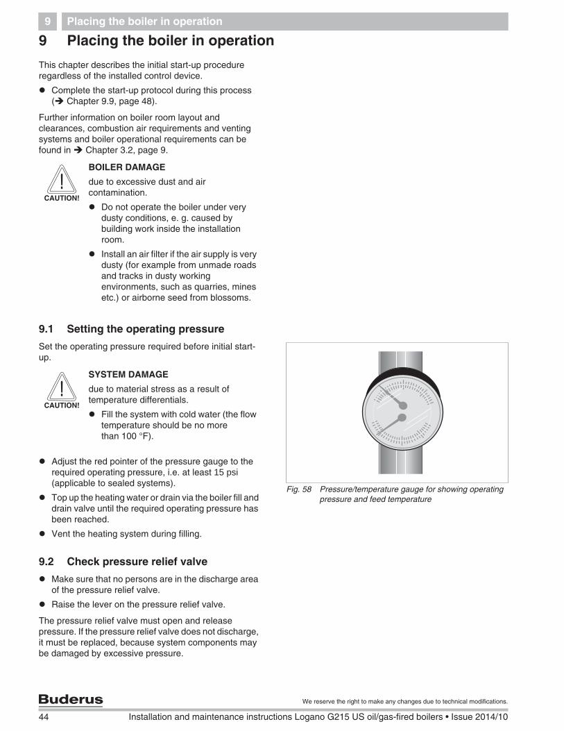
9.1 Setting the operating pressure
Set the operating pressure required before initial start-up.
Adjust the red pointer of the pressure gauge to therequired operating pressure, i.e. at least 15 psi(applicable to sealed systems).
Top up the heating water or drain via the boiler fill anddrain valve until the required operating pressure hasbeen reached.
Vent the heating system during filling.
9.2 Check pressure relief valve
Make sure that no persons are in the discharge areaof the pressure relief valve.
Raise the lever on the pressure relief valve.
The pressure relief valve must open and releasepressure. If the pressure relief valve does not discharge,it must be replaced, because system components maybe damaged by excessive pressure.
CAUTION!
BOILER DAMAGE
due to excessive dust and aircontamination.
Do not operate the boiler under verydusty conditions, e. g. caused bybuilding work inside the installationroom.
Install an air filter if the air supply is verydusty (for example from unmade roadsand tracks in dusty workingenvironments, such as quarries, minesetc.) or airborne seed from blossoms.
Fig. 58 Pressure/temperature gauge for showing operatingpressure and feed temperature
CAUTION!
SYSTEM DAMAGE
due to material stress as a result oftemperature differentials.
Fill the system with cold water (the flowtemperature should be no morethan 100 °F).
Placing the boiler in operation 9
45
We reserve the right to make any changes due to technical modifications.
Installation and maintenance instructions Logano G215 US oil/gas-fired boilers • Issue 2014/10
9.3 Making the heating system operational
Open fuel feed on the main shut-off valve.
Switch on the heating system emergency stop switch(if installed) and/or switch the corresponding housecircuit-breaker.
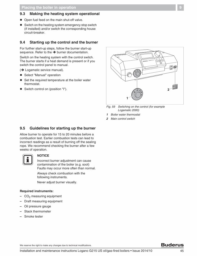
9.4 Starting up the control and the burner
For further start-up steps, follow the burner start-upsequence. Refer to the burner documentation.
Switch on the heating system with the control switch.The burner starts if a heat demand is present or if youswitch the control panel to manual.
( Logamatic service manual).
Select "Manual" operation
Set the required temperature at the boiler waterthermostat.
Switch control on (position "I").
9.5 Guidelines for starting up the burner
Allow burner to operate for 15 to 20 minutes before acombustion test. Earlier combustion tests can lead toincorrect readings as a result of burning off the sealingrope. We recommend checking the burner after a fewweeks of operation.
Required instruments:
– CO2 measuring equipment
– Draft measuring equipment
– Oil pressure gauge
– Stack thermometer
– Smoke tester
Fig. 59 Switching on the control (for exampleLogamatic 2000)
1 Boiler water thermostat2 Main control switch
� �
2
1
NOTICE
Incorrect burner adjustment can causecontamination of the boiler (e.g. soot)Faults may occur more often than normal.
Always check combustion with thefollowing instruments.
Never adjust burner visually.
46 Installation and maintenance instructions Logano G215 US oil/gas-fired boilers • Issue 2014/10
We reserve the right to make any changes due to technical modifications.
Placing the boiler in operation9
Check the firebox pressure at the test port.
Check the breeching draft at a test port drilled in thevent connector (chimney vent models only).
9.6 Raising flue gas temperature
For the set flue gas temperature for the boiler see thetechnical data ( Chapter 3, page 8)
You may raise the flue gas temperature if you discoverduring tests that the flue gas temperature is too low forthe type of chimney used (risk of condensation) by oneor several of the following measures:
– Remove flue gas baffle plates
– Remove the flue gas check plate
Shut down the heating system ( Chapter 10.1,page 49).
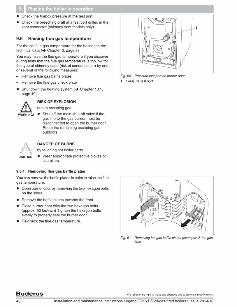
9.6.1 Removing flue gas baffle plates
You can remove the baffle plates in pairs to raise the fluegas temperature.
Open burner door by removing the two hexagon boltson the sides.
Remove the baffle plates towards the front.
Close burner door with the two hexagon bolts(approx. 90 lbs/inch) Tighten the hexagon boltsevenly to properly seal the burner door.
Re-check the flue gas temperature.
Fig. 60 Pressure test port on burner door
1 Pressure test port
1
WARNING!
RISK OF EXPLOSION
due to escaping gas.
Shut off the main shut-off valve if thegas line to the gas burner must bedisconnected to open the burner door.Route the remaining escaping gasoutdoors.
CAUTION!
DANGER OF BURNS
by touching hot boiler parts.
Wear appropriate protective gloves oruse pliers.
Fig. 61 Removing hot gas baffle plates (example: 2. hot gasflue)
Placing the boiler in operation 9
47
We reserve the right to make any changes due to technical modifications.
Installation and maintenance instructions Logano G215 US oil/gas-fired boilers • Issue 2014/10
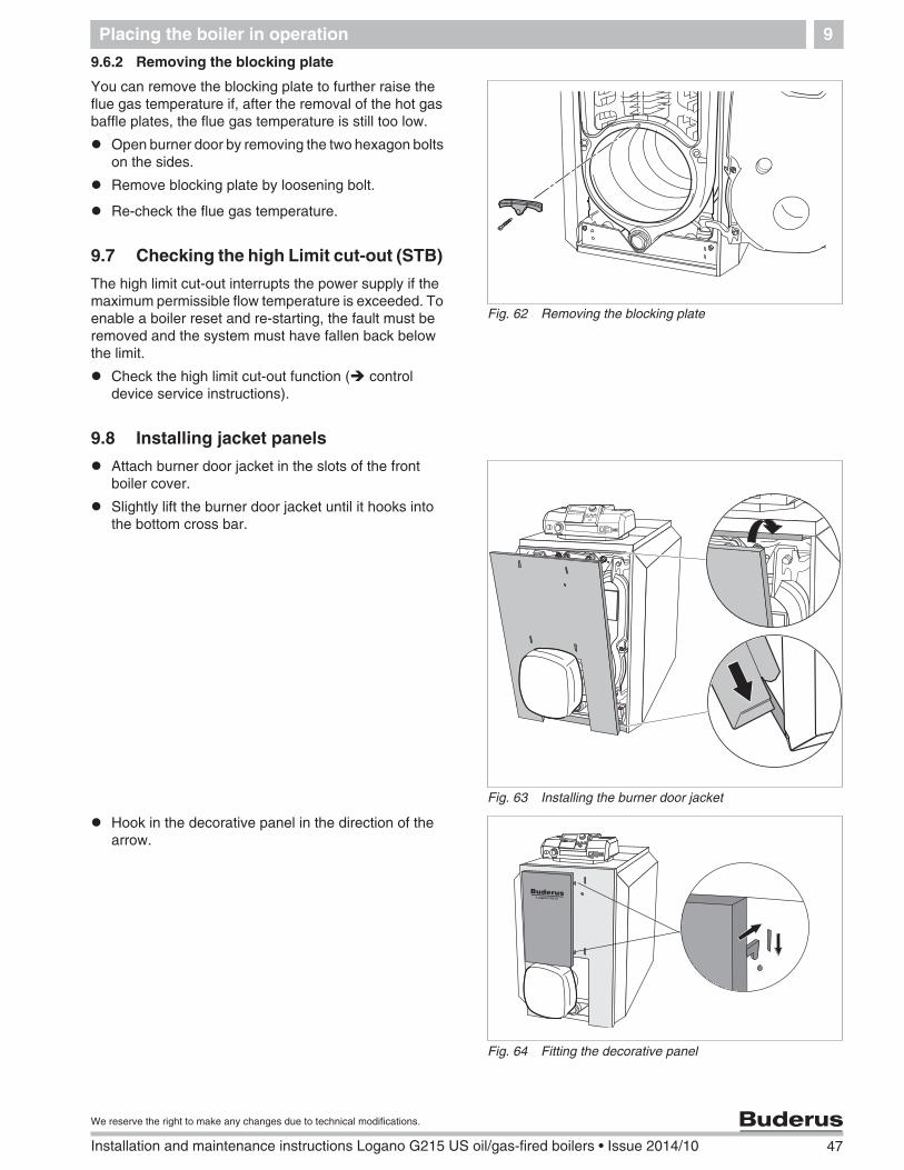
9.6.2 Removing the blocking plate
You can remove the blocking plate to further raise theflue gas temperature if, after the removal of the hot gasbaffle plates, the flue gas temperature is still too low.
Open burner door by removing the two hexagon boltson the sides.
Remove blocking plate by loosening bolt.
Re-check the flue gas temperature.
9.7 Checking the high Limit cut-out (STB)
The high limit cut-out interrupts the power supply if themaximum permissible flow temperature is exceeded. Toenable a boiler reset and re-starting, the fault must beremoved and the system must have fallen back belowthe limit.
Check the high limit cut-out function ( controldevice service instructions).
9.8 Installing jacket panels
Attach burner door jacket in the slots of the frontboiler cover.
Slightly lift the burner door jacket until it hooks intothe bottom cross bar.
Hook in the decorative panel in the direction of thearrow.
Fig. 62 Removing the blocking plate
Fig. 63 Installing the burner door jacket
Fig. 64 Fitting the decorative panel
48 Installation and maintenance instructions Logano G215 US oil/gas-fired boilers • Issue 2014/10
We reserve the right to make any changes due to technical modifications.
Placing the boiler in operation9
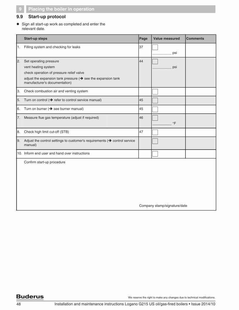
9.9 Start-up protocol
Sign all start-up work as completed and enter therelevant date.
Start-up steps Page Value measured Comments
1. Filling system and checking for leaks 37
__________ psi
2. Set operating pressure
vent heating system
check operation of pressure relief valve
adjust the expansion tank pressure ( see the expansion tankmanufacturer's documentation)
44
__________ psi
3. Check combustion air and venting system
5. Turn on control ( refer to control service manual) 45
6. Turn on burner ( see burner manual) 45
7. Measure flue gas temperature (adjust if required) 46
__________ °F
8. Check high limit cut-off (STB) 47
9. Adjust the control settings to customer's requirements ( control servicemanual)
10. Inform end user and hand over instructions
Confirm start-up procedure
Company stamp/signature/date
Taking the boiler out of operation 10
49
We reserve the right to make any changes due to technical modifications.
Installation and maintenance instructions Logano G215 US oil/gas-fired boilers • Issue 2014/10
10 Taking the boiler out of operation
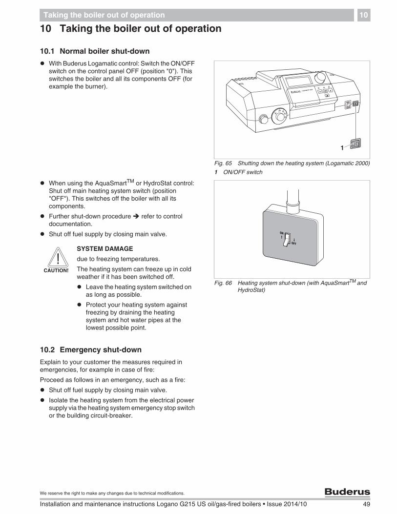
10.1 Normal boiler shut-down
With Buderus Logamatic control: Switch the ON/OFFswitch on the control panel OFF (position "0"). Thisswitches the boiler and all its components OFF (forexample the burner).
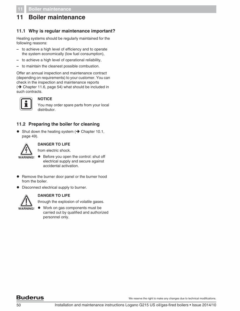
When using the AquaSmartTM or HydroStat control:Shut off main heating system switch (position"OFF"). This switches off the boiler with all itscomponents.
Further shut-down procedure refer to controldocumentation.
Shut off fuel supply by closing main valve.
10.2 Emergency shut-down
Explain to your customer the measures required inemergencies, for example in case of fire:
Proceed as follows in an emergency, such as a fire:
Shut off fuel supply by closing main valve.
Isolate the heating system from the electrical powersupply via the heating system emergency stop switchor the building circuit-breaker.
Fig. 65 Shutting down the heating system (Logamatic 2000)
1 ON/OFF switch
� �
1
Fig. 66 Heating system shut-down (with AquaSmartTM andHydroStat)
CAUTION!
SYSTEM DAMAGE
due to freezing temperatures.
The heating system can freeze up in coldweather if it has been switched off.
Leave the heating system switched onas long as possible.
Protect your heating system againstfreezing by draining the heatingsystem and hot water pipes at thelowest possible point.
50 Installation and maintenance instructions Logano G215 US oil/gas-fired boilers • Issue 2014/10
We reserve the right to make any changes due to technical modifications.
Boiler maintenance11
11 Boiler maintenance
11.1 Why is regular maintenance important?
Heating systems should be regularly maintained for thefollowing reasons:
– to achieve a high level of efficiency and to operatethe system economically (low fuel consumption),
– to achieve a high level of operational reliability,
– to maintain the cleanest possible combustion.
Offer an annual inspection and maintenance contract(depending on requirements) to your customer. You cancheck in the inspection and maintenance reports( Chapter 11.6, page 54) what should be included insuch contracts.
11.2 Preparing the boiler for cleaning
Shut down the heating system ( Chapter 10.1,page 49).
Remove the burner door panel or the burner hoodfrom the boiler.
Disconnect electrical supply to burner.
NOTICE
You may order spare parts from your localdistributor.
WARNING!
DANGER TO LIFE
from electric shock.
Before you open the control: shut offelectrical supply and secure againstaccidental activation.
WARNING!
DANGER TO LIFE
through the explosion of volatile gases.
Work on gas components must becarried out by qualified and authorizedpersonnel only.
Boiler maintenance 11
51
We reserve the right to make any changes due to technical modifications.
Installation and maintenance instructions Logano G215 US oil/gas-fired boilers • Issue 2014/10
11.3 Boiler cleaning
The boiler can be cleaned with brushes and/or by a wetmethod. Cleaning equipment is available as accessory.
Open burner door by removing the two hexagon boltson the sides.
11.3.1 Cleaning the boiler with cleaning brushes
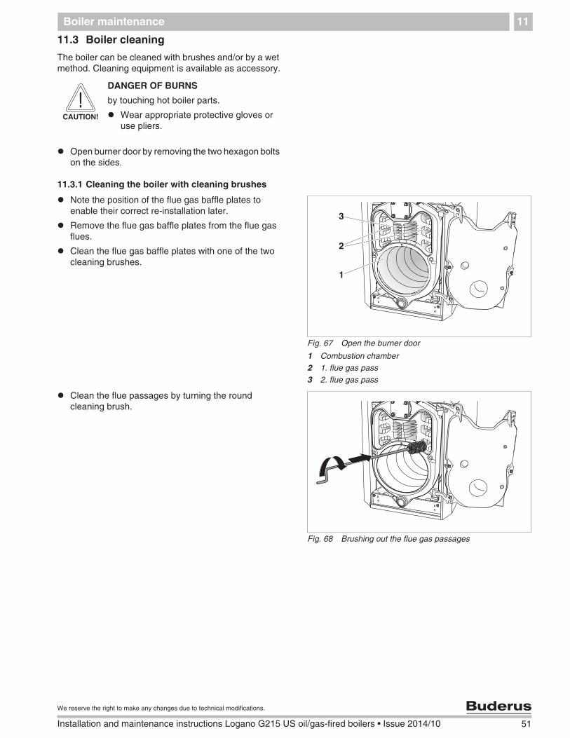
Note the position of the flue gas baffle plates toenable their correct re-installation later.
Remove the flue gas baffle plates from the flue gasflues.
Clean the flue gas baffle plates with one of the twocleaning brushes.
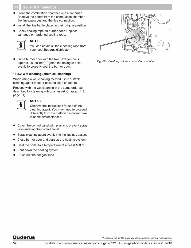
Clean the flue passages by turning the roundcleaning brush.
CAUTION!
DANGER OF BURNS
by touching hot boiler parts.
Wear appropriate protective gloves oruse pliers.
Fig. 67 Open the burner door
1 Combustion chamber2 1. flue gas pass3 2. flue gas pass
1
3
2
Fig. 68 Brushing out the flue gas passages
52 Installation and maintenance instructions Logano G215 US oil/gas-fired boilers • Issue 2014/10
We reserve the right to make any changes due to technical modifications.
Boiler maintenance11
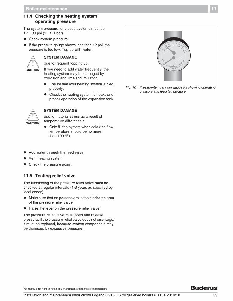
Clean the combustion chamber with a flat brush.Remove the debris from the combustion chamber,the flue passages and the flue connection.
Install the flue baffle plates in their original position.
Check sealing rope on burner door. Replacedamaged or hardened sealing rope.
Close burner door with the two hexagon bolts(approx. 90 lbs/inch) Tighten the hexagon boltsevenly to properly seal the burner door.
11.3.2 Wet cleaning (chemical cleaning)
When using a wet cleaning method use a suitablecleaning agent (soot or accumulation of debris).
Proceed with the wet cleaning in the same order asdescribed for cleaning with brushes ( Chapter 11.3.1,page 51).
Cover the control panel with plastic to prevent sprayfrom entering the control panel.
Spray cleaning agent evenly into the flue gas passes.
Close burner door and start up the heating system.
Heat the boiler to a temperature of at least 160 °F.
Shut down the heating system.
Brush out the hot gas flues.
Fig. 69 Brushing out the combustion chamber
NOTICE
You can obtain suitable sealing rope fromyour local Buderus distributor.
NOTICE
Observe the instructions for use of thecleaning agent. You may need to proceeddifferently from the method described herein some circumstances.
Boiler maintenance 11
53
We reserve the right to make any changes due to technical modifications.
Installation and maintenance instructions Logano G215 US oil/gas-fired boilers • Issue 2014/10
11.4 Checking the heating systemoperating pressure
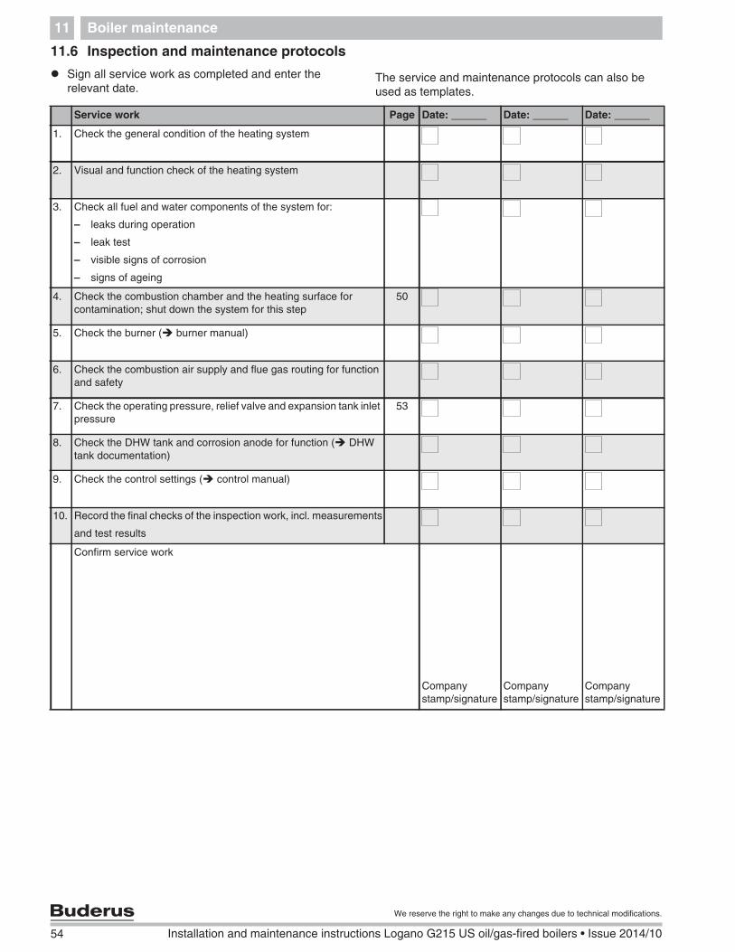
The system pressure for closed systems must be12 – 30 psi (1 – 2.1 bar).
Check system pressure
If the pressure gauge shows less than 12 psi, thepressure is too low. Top up with water.
Add water through the feed valve.
Vent heating system
Check the pressure again.
11.5 Testing relief valve
The functioning of the pressure relief valve must bechecked at regular intervals (1-3 years as specified bylocal codes).
Make sure that no persons are in the discharge areaof the pressure relief valve.
Raise the lever on the pressure relief valve.
The pressure relief valve must open and releasepressure. If the pressure relief valve does not discharge,it must be replaced, because system components maybe damaged by excessive pressure.
Fig. 70 Pressure/temperature gauge for showing operatingpressure and feed temperature
CAUTION!
SYSTEM DAMAGE
due to frequent topping up.
If you need to add water frequently, theheating system may be damaged bycorrosion and lime accumulation.
Ensure that your heating system is bledproperly.
Check the heating system for leaks andproper operation of the expansion tank.
CAUTION!
SYSTEM DAMAGE
due to material stress as a result oftemperature differentials.
Only fill the system when cold (the flowtemperature should be no morethan 100 °F).
54 Installation and maintenance instructions Logano G215 US oil/gas-fired boilers • Issue 2014/10
We reserve the right to make any changes due to technical modifications.
Boiler maintenance11
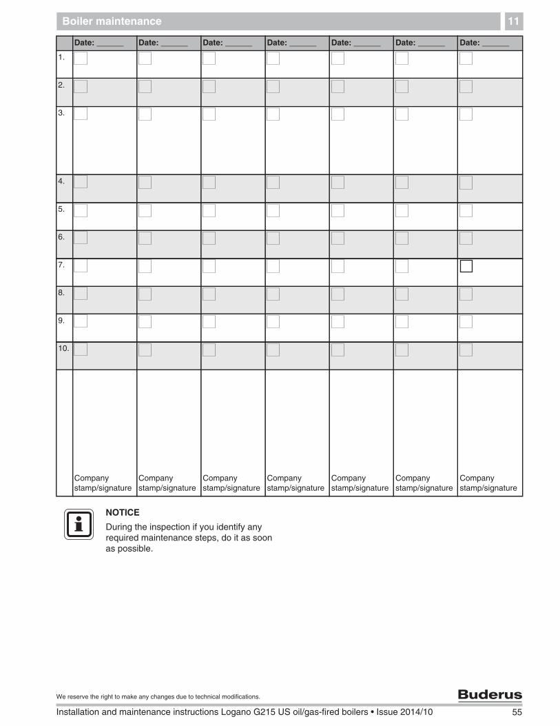
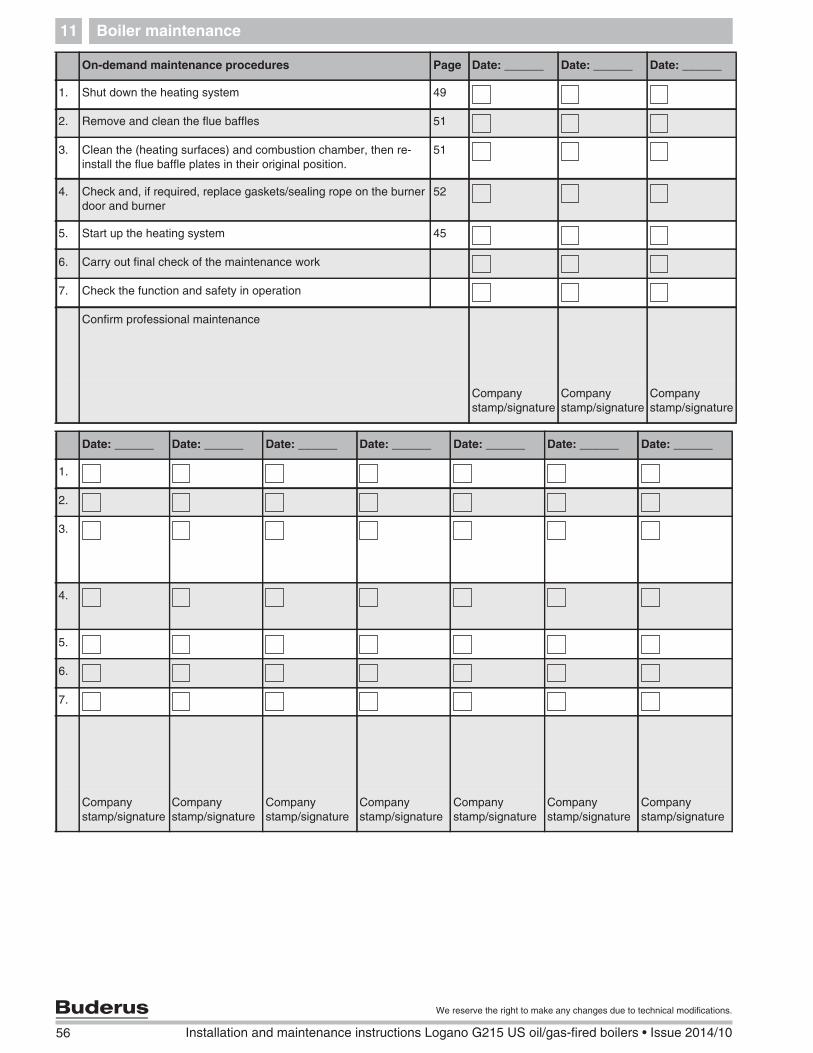
11.6 Inspection and maintenance protocols
Sign all service work as completed and enter therelevant date.
The service and maintenance protocols can also beused as templates.
Service work Page Date: ______ Date: ______ Date: ______
1. Check the general condition of the heating system
2. Visual and function check of the heating system
3. Check all fuel and water components of the system for:
– leaks during operation
– leak test
– visible signs of corrosion
– signs of ageing
4. Check the combustion chamber and the heating surface forcontamination; shut down the system for this step
50
5. Check the burner ( burner manual)
6. Check the combustion air supply and flue gas routing for functionand safety
7. Check the operating pressure, relief valve and expansion tank inletpressure
53
8. Check the DHW tank and corrosion anode for function ( DHWtank documentation)
9. Check the control settings ( control manual)
10. Record the final checks of the inspection work, incl. measurements
and test results
Confirm service work
Companystamp/signature
Companystamp/signature
Companystamp/signature
Boiler maintenance 11
55
We reserve the right to make any changes due to technical modifications.
Installation and maintenance instructions Logano G215 US oil/gas-fired boilers • Issue 2014/10
We reserve the right to make any changes due to technical modifications.
Installation and maintenance instructions Logano G215 US oil/gas-fired boilers • Issue 2014/10
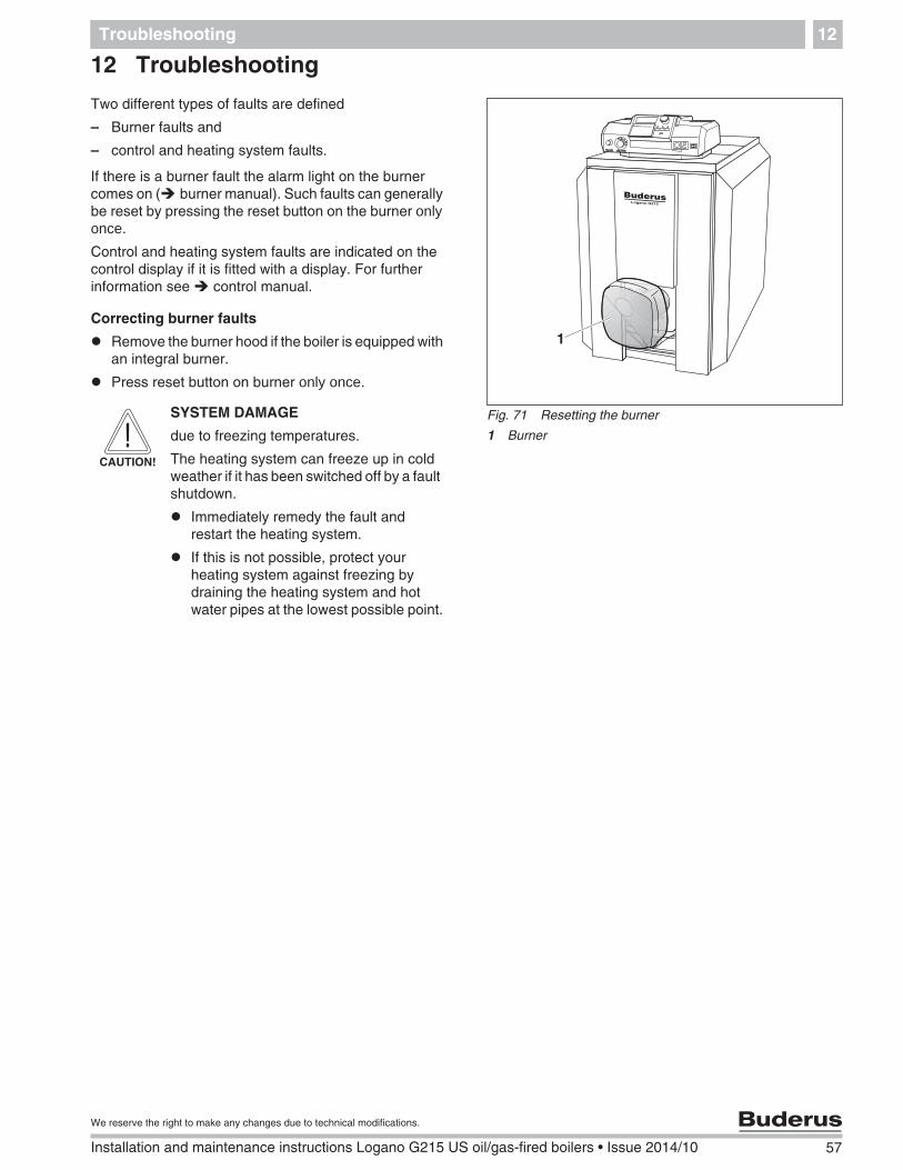
12 Troubleshooting
Two different types of faults are defined
– Burner faults and
– control and heating system faults.
If there is a burner fault the alarm light on the burnercomes on ( burner manual). Such faults can generallybe reset by pressing the reset button on the burner only once.
Control and heating system faults are indicated on thecontrol display if it is fitted with a display. For furtherinformation see control manual.
Correcting burner faults
Remove the burner hood if the boiler is equipped withan integral burner.
Press reset button on burner only once.
Fig. 71 Resetting the burner
1 Burner
1
CAUTION!
SYSTEM DAMAGE
due to freezing temperatures.
The heating system can freeze up in coldweather if it has been switched off by a faultshutdown.
Immediately remedy the fault andrestart the heating system.
If this is not possible, protect yourheating system against freezing bydraining the heating system and hotwater pipes at the lowest possible point.
58 Installation and maintenance instructions Logano G215 US oil/gas-fired boilers • Issue 2014/10
We reserve the right to make any changes due to technical modifications.
Examples of installations13
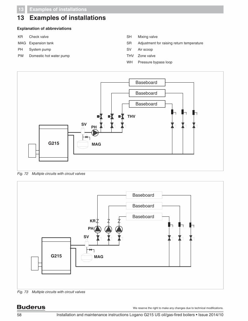
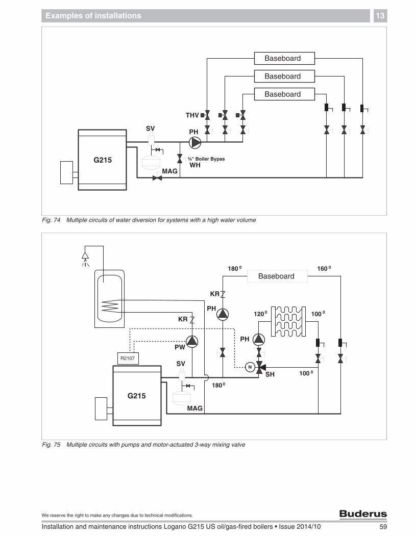
13 Examples of installations
Explanation of abbreviations
KR Check valve SH Mixing valve
MAG Expansion tank SR Adjustment for raising return temperature
PH System pump SV Air scoop
PW Domestic hot water pump THV Zone valve
WH Pressure bypass loop
Fig. 72 Multiple circuits with circuit valves
SVPH
MAG
THV
Fig. 73 Multiple circuits with circuit valves
SV
PH
MAG
KR
Examples of installations 13
59
We reserve the right to make any changes due to technical modifications.
Installation and maintenance instructions Logano G215 US oil/gas-fired boilers • Issue 2014/10
Fig. 74 Multiple circuits of water diversion for systems with a high water volume
SV PH
MAGWH
THV
Fig. 75 Multiple circuits with pumps and motor-actuated 3-way mixing valve
SV
PH
MAG
SH
KR
PH
KR
PW
60 Installation and maintenance instructions Logano G215 US oil/gas-fired boilers • Issue 2014/10
We reserve the right to make any changes due to technical modifications.
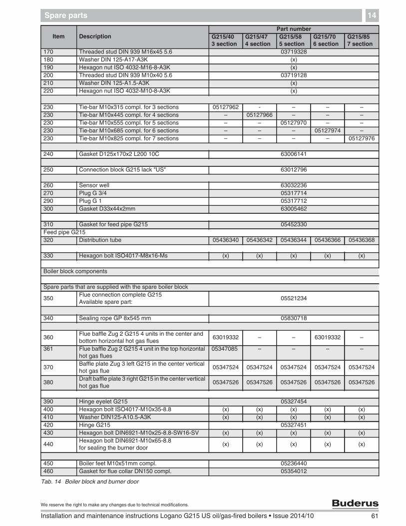
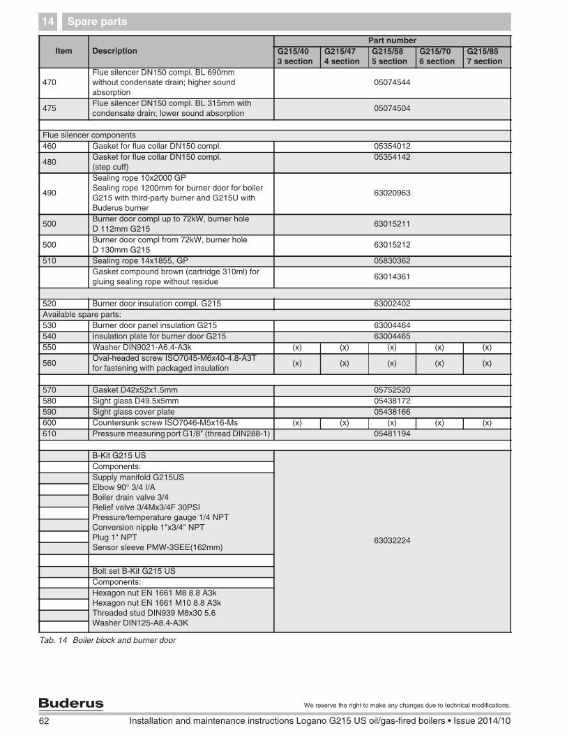
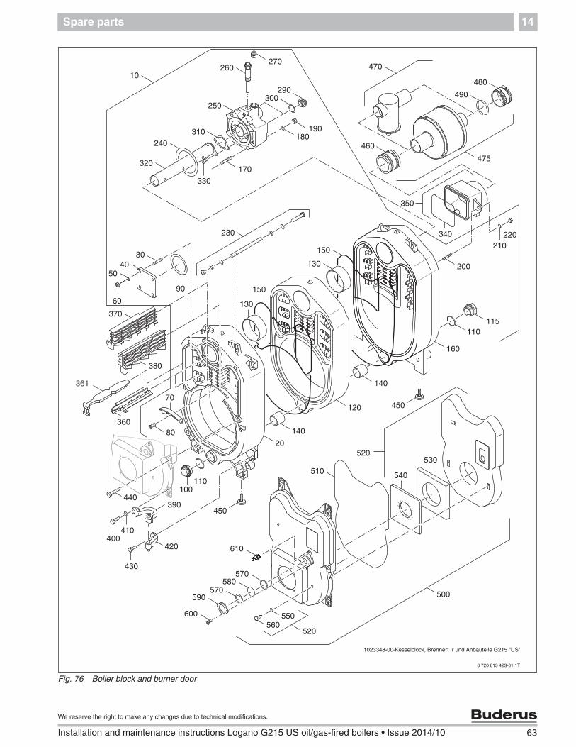
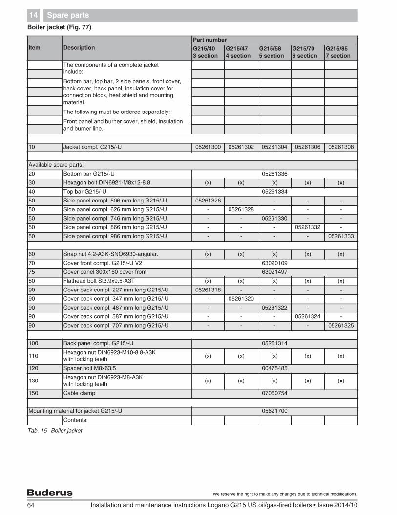
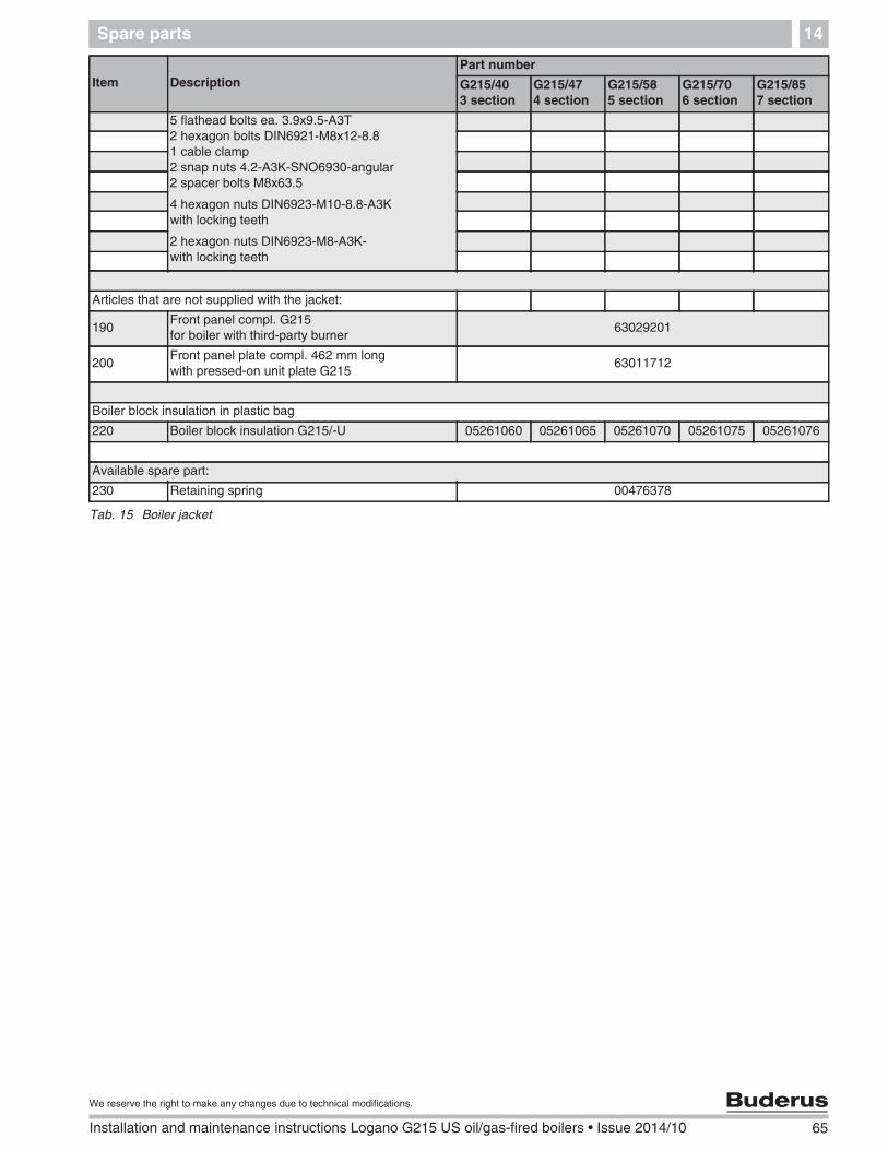
Spare parts14
14 Spare parts
The following parts are available from your Buderusdistributor. If there are several Buderus part numbers forone item number, the numbers for the various modelsare listed in the relevant columns. Otherwise the tableshows the number of components for each model.
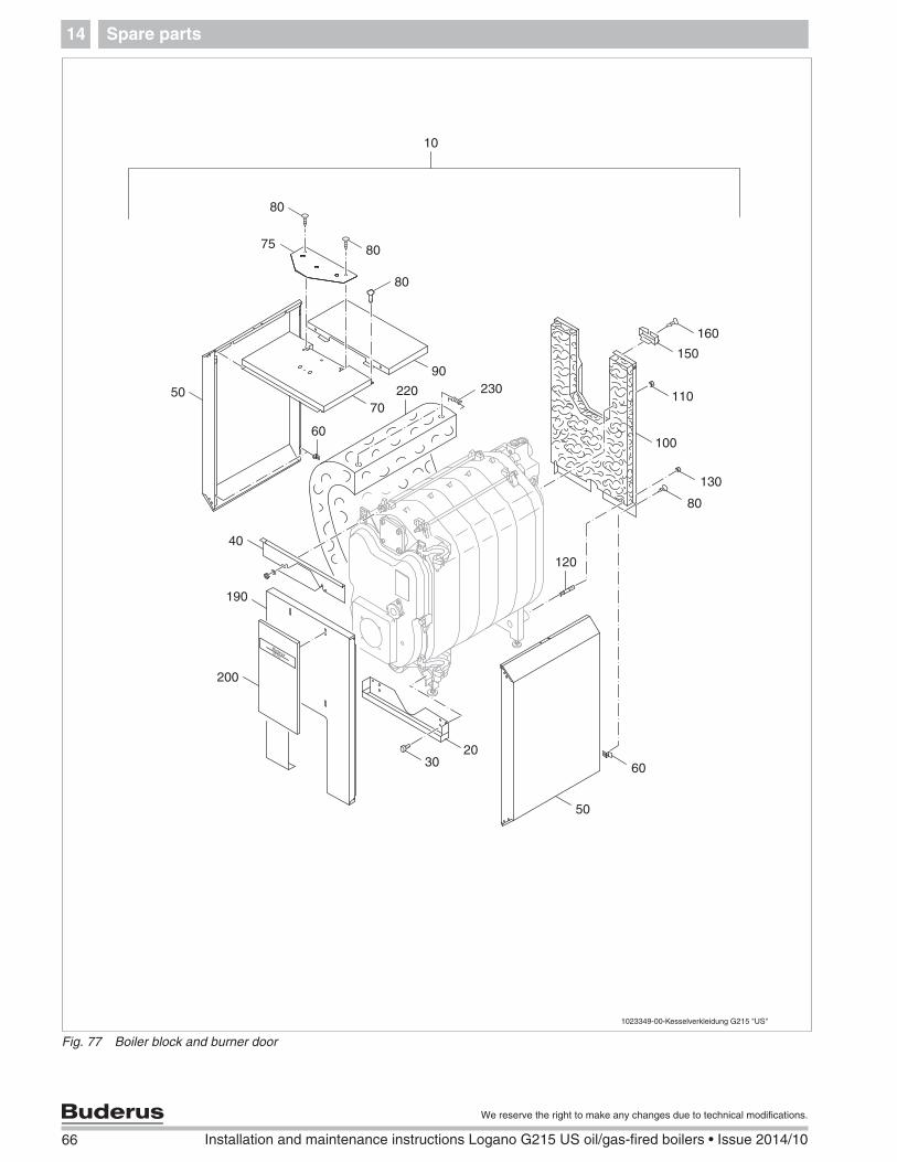
Boiler block and burner door (Fig. 76)
Legend for tables 14 and 15:x = no spare part(x) = component of a set, only available with set0 = no picture available
68 Installation and maintenance instructions Logano G215 US oil/gas-fired boilers • Issue 2014/10
We reserve the right to make any changes due to technical modifications.
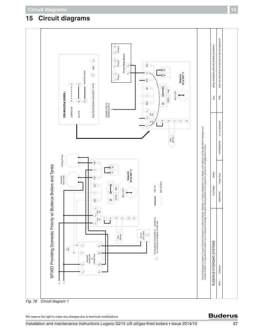
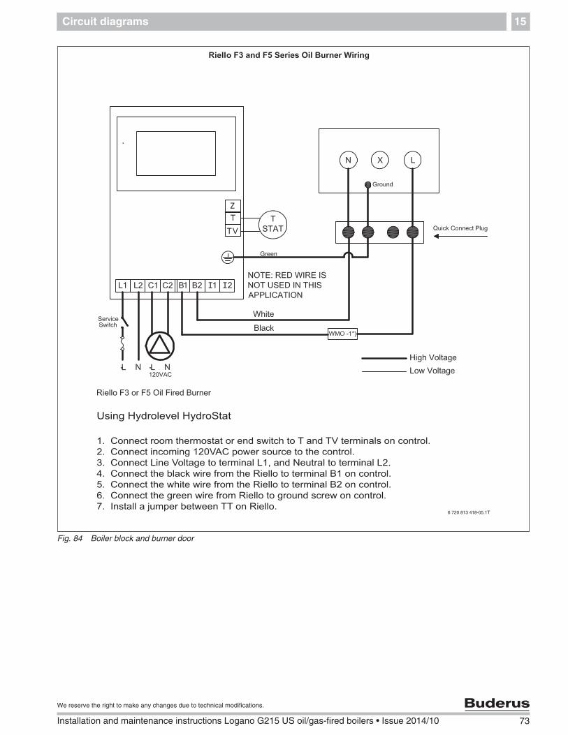
Circuit diagrams15
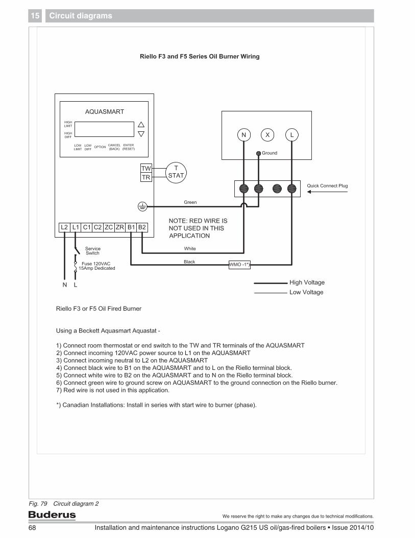
Fig. 79 Circuit diagram 2
Circuit diagrams 15
69
We reserve the right to make any changes due to technical modifications.
Installation and maintenance instructions Logano G215 US oil/gas-fired boilers • Issue 2014/10
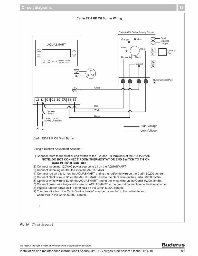
Fig. 80 Circuit diagram 3
70 Installation and maintenance instructions Logano G215 US oil/gas-fired boilers • Issue 2014/10
We reserve the right to make any changes due to technical modifications.
Circuit diagrams15
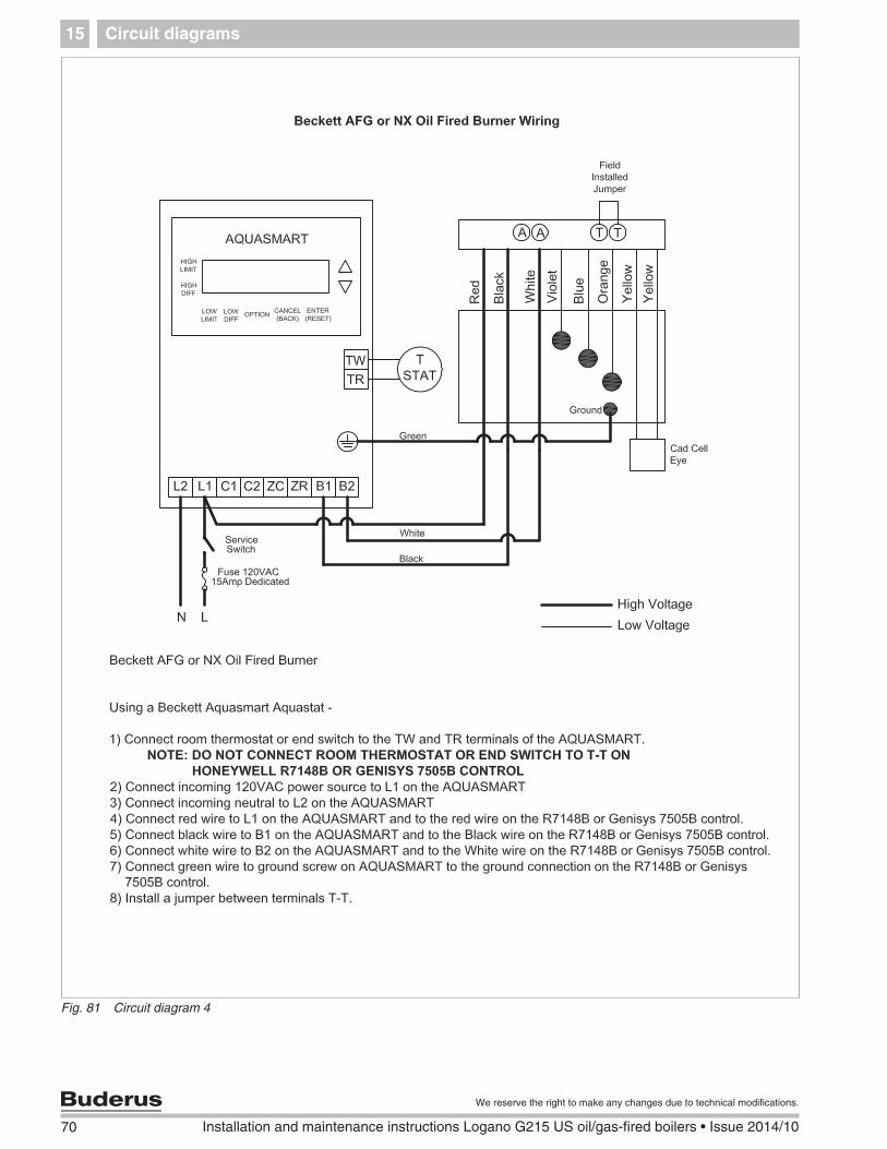
Fig. 81 Circuit diagram 4
Circuit diagrams 15
71
We reserve the right to make any changes due to technical modifications.
Installation and maintenance instructions Logano G215 US oil/gas-fired boilers • Issue 2014/10
Fig. 82 Boiler block and burner door
I I
Z
Using Hydrolevel HydroStat with Honeywell R7148B or Genisys 7505B
1. Connect room thermostat or end switch to T and TV terminals on control.2. Connect incoming 120VAC power source to the control.3. Connect Line Voltage to terminal L1, and Neutral to terminal L2.4. Connect the black wire from the Honeywell or Genisys to terminal B1 on control.5. Connect the white wire from the Honeywell or Genisys to terminal B2 on control.6. Connect the green wire from Honeywell or Genisys to ground screw on control.7. Connect the red wire from the Honeywell or Genisys to L1 on control.8. Install a jumper between TT on Honeywell or Genisys. NOTE: Do not connect a room thermostat or end switch to TT on the Honeywell R7148B or Genisys 7505B control.
6 720 813 418-03.1T
72 Installation and maintenance instructions Logano G215 US oil/gas-fired boilers • Issue 2014/10
We reserve the right to make any changes due to technical modifications.
Circuit diagrams15
Fig. 83 Boiler block and burner door
I I
Z
Using Hydrolevel HydroStat
1. Connect room thermostat or end switch to T and TV terminals on control.2. Connect incoming 120VAC power source to the control.3. Connect Line Voltage to terminal L1, and Neutral to terminal L2.4. Connect the black wire from the Carlin 60200 to terminal B1 on control.5. Connect the white wire from the Carlin 60200 to terminal B2 on control.6. Connect the green wire from Carlin 60200 to ground screw on control.7. Install a jumper between TT on Carlin 60200.8. The pink wire from the Carlin “in-line heater” may be connected to the red/white wire in the Carlin 60200 control.
6 720 813 418-04.1T
Circuit diagrams 15
73
We reserve the right to make any changes due to technical modifications.
Installation and maintenance instructions Logano G215 US oil/gas-fired boilers • Issue 2014/10
Fig. 84 Boiler block and burner door
I I
Z
Using Hydrolevel HydroStat
1. Connect room thermostat or end switch to T and TV terminals on control.2. Connect incoming 120VAC power source to the control.3. Connect Line Voltage to terminal L1, and Neutral to terminal L2.4. Connect the black wire from the Riello to terminal B1 on control.5. Connect the white wire from the Riello to terminal B2 on control.6. Connect the green wire from Riello to ground screw on control.7. Install a jumper between TT on Riello.
6 720 813 418-05.1T
Table of Key Words16
74 Installation and maintenance instructions Logano G215 US oil/gas-fired boilers • Issue 2014/10
We reserve the right to make any changes due to technical modifications.
16 Table of Key Words
AAnchor rods .......................................................... 23Assembly of boiler sections ............................. 17
BB-Kit components: .............................................. 13Blank flange ......................................................... 25Boiler back panel ................................................ 29Boiler block ........................................................... 60Boiler block leak test .......................................... 26Boiler fill & drain valve ....................................... 25Boiler room ............................................................. 6Burner door .......................................................... 60Burner door installation ..................................... 28Burner installation ............................................... 38Burner, guidelines for starting up ................... 45
CCable entry ........................................................... 33Capillary tubes ..................................................... 41Check the temperature safety cut-out (STB) ..47Checking for leaks (heating water side) ....... 37Circuit diagrams .................................................. 67Clearances ........................................................... 15Combustion chamber ........................................ 51Compression tool ................................................ 20Connect electrical power supply .................... 43Correcting burner faults .................................... 57
FFitting adjustable feet ........................................ 27Fitting the control panel .................................... 40Fitting the side panels ....................................... 31Fitting the tie-bars ............................................... 30Flue outlet ............................................................. 25
IIf you notice a smell of gas .................................5Initial start-up ........................................................44Inserting the hot gas baffle plates ..................28Installation diagram ............................................37Installation of boiler drain ..................................36Installation of the boiler jacket .........................29Installing B-Kit ......................................................36Installing boiler fill and drain valve .................36Installing the boiler cover ..................................32Installing the burner door jacket ......................47Installing the temperature sensor set ............41Installing thermal insulation ..............................31Insulation ...............................................................31
OON/OFF switch ....................................................49On-site test pressure ..........................................38Original components ............................................5
PPressure relief valve .............................. 36, 38, 44Pressure test port ................................................46Pressure/temperature gauge .....................44, 53Protocol, start-up .................................................48Protocols, inspection and maintenance ........54Providing a fuel supply ......................................39
RRaising flue gas temperature ...........................46Routing the burner cable ...................................41
SSealing rope, replacing ......................................52Sealing the boiler hub ........................................25Sensor well ............................................................24Sensor wire ...........................................................41Shutting down ......................................................49Side panels ...........................................................31Strain relief installation ......................................43Supply/return header ..........................................23
Table of Key Words 16
75
We reserve the right to make any changes due to technical modifications.
Installation and maintenance instructions Logano G215 US oil/gas-fired boilers • Issue 2014/10
TTechnical information ...........................................8Test port .......................................................... 24, 41Tools ..........................................................................6Troubleshooting ...................................................57