Installation and Maintenance Instructions B-2701, B-2703, B-2710 & B-2711 SERIES SINGLE LEVER FAUCETS (with or without Pop-Up) Limited One Year Warranty T&S warrants to the original purchaser (other than for purposes of resale) that such product is free from defects in material and workmanship for a period of one (1) year from the date of purchase. During this one-year warranty period, if the product is found to be defective, T&S shall, at its options, repair and/or replace it. To obtain warranty service, products must be returned to... T&S Brass and Bronze Works, Inc. Attn: Warranty Repair Department 2 Saddleback Cove Travelers Rest, SC 29690 Shipping, freight, insurance, and other transportation charges of the product to T&S and the return of repaired or replaced product to the purchaser are the responsibility of the purchaser. Repair and/or replacement shall be made within a reasonable time after receipt by T&S of the returned product. This warranty does not cover Items which have received secondary finishing or have been altered or modified after purchase, or for defects caused by physical abuse to or misuse of the product, or shipment of the products. Any express warranty not provided herein, and any remedy for Breach of Contract which might arise, is hereby excluded and disclaimed. Any implied warranties of merchantability or fitness for a particular purpose are limited to one year in duration. Under no circumstances shall T&S be liable for loss of use or any special consequential costs, expenses or damages. Some states do not allow limitations on how long and implied warranty lasts or the exclusion or limitation of incidental or consequential dam- ages, so the above limitations or exclusions may not apply to you. Specific rights under this war- ranty and other rights vary from state to state. P/N: 098-013122-45 Rev.5 Date: 03-09-11 Drawn: TEH Checked: DMH 03-11-11 Approved: JHB 03-16-11
Transcript
Installation and MaintenanceInstructions
B-2701, B-2703, B-2710 & B-2711 SERIESSINGLE LEVER FAUCETS (with or without Pop-Up)
Limited One Year Warranty T&S warrants to the original purchaser (other than for purposes of resale) that such product is free from defects in material and workmanship for a period of one (1) year from the date of purchase. During this one-year warranty period, if the product is found to be defective, T&S shall, at its options, repair and/or replace it. To obtain warranty service, products must be returned to...
T&S Brass and Bronze Works, Inc.Attn: Warranty Repair Department
2 Saddleback CoveTravelers Rest, SC 29690
Shipping, freight, insurance, and other transportation charges of the product to T&S and the return of repaired or replaced product to the purchaser are the responsibility of the purchaser. Repair and/or replacement shall be made within a reasonable time after receipt by T&S of the returned product. This warranty does not cover Items which have received secondary fi nishing or have been altered or modifi ed after purchase, or for defects caused by physical abuse to or misuse of the product, or shipment of the products. Any express warranty not provided herein, and any remedy for Breach of Contract which might arise, is hereby excluded and disclaimed. Any implied warranties of merchantability or fi tness for a particular purpose are limited to one year in duration. Under no circumstances shall T&S be liable for loss of use or any special consequential costs, expenses or damages. Some states do not allow limitations on how long and implied warranty lasts or the exclusion or limitation of incidental or consequential dam-ages, so the above limitations or exclusions may not apply to you. Specifi c rights under this war-ranty and other rights vary from state to state.
Asm, Single Lever Rigid Base FaucetAsm, Single Lever Rigid Base Faucet w/ 4” DeckplateAsm, Single Lever Faucet w/ Pop-Up DrainAsm, Single Lever FaucetGasket, WaterproofLock WasherLock NutKit, Lock Washer and Lock NutFaucet BodyHandlePlug3/32” or 2.5mm Hex Key (not included)Pop-Up DrainCartridge, Metal Stem w/ Temperature Limit StopRetaining NutRetaining Ring4” Deckplate
Faucet Installation (B-2710 & B-2711)(Refer to diagram below)
1. Shut off water supply and drain lines. Clean sink surface throughly.
2. Install no.5 with no.2 on top of the deck or sink.
3. Place no.3 and no.4 on the shank of no.5 and tighten fully.
3. Insert drain body from bottom of sink drain hole, reassemble fl ange to drain body, tightening as far possible.
rod clip
pop-up drain stopper
nut
o-ring
stem
screwrubber washer
fl ange
washer
gasket
lift rodlocknutball rod
drain body
4. Slide rubber washer on drain pipe up against bottom of sink. Tighten washer and locknut fi rmly against base for a tight seal.
fl ange drain pipe
drain body
fl ange fl ush with sink bottom
rubberwasher
locknut
sink base
Pop-Up Valve Installation1. Remove pop-up drain stopper, with o-ring and fl ange, from pop-up assembly.
2. Remove rod clip, lift rod, rod guide nut and rod ball assembly from drain body.
5
deck34
4. Connect water supply lines and check for leaks.
2
washer
Faucet Installation (B-2701 & B-2703)(Refer to diagram on page 2)
1. Shut off water supply lines. Drill a 1-1/2” diameter hole in countertop where no.5 will be installed.
2. Clean countertop and bottom of no.5. Ap-ply putty to bottom of no.5.
3. If installing no.13, apply putty to bottom contact face of no.13.
4. With no.14 and no.15 removed place hoses and threaded rod at bottom of no.5 through the 1-1/2” diameter hole.
5. Place no.14 and no.15 on threaded rod and tighten.
6. Connect water supply and check for leaks.
General Instructions
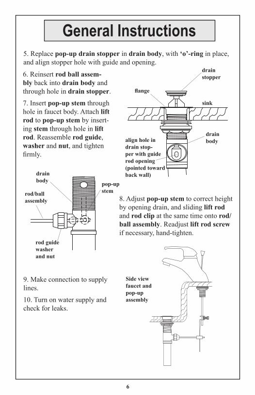
5. Replace pop-up drain stopper in drain body, with ‘o’-ring in place, and align stopper hole with guide and opening.
drain stopper
fl ange
drain bodyalign hole in
drain stop-per with guide rod opening (pointed toward back wall)
sink
6. Reinsert rod ball assem-bly back into drain body and through hole in drain stopper.
7. Insert pop-up stem through hole in faucet body. Attach lift rod to pop-up stem by insert-ing stem through hole in lift rod. Reassemble rod guide, washer and nut, and tighten fi rmly.
8. Adjust pop-up stem to correct height by opening drain, and sliding lift rod and rod clip at the same time onto rod/ball assembly. Readjust lift rod screw if necessary, hand-tighten.
rod/ball assembly
drain body pop-up
stem
rod guide washer and nut
Side view faucet and pop-up assembly
9. Make connection to supply lines.
10. Turn on water supply and check for leaks.
6
General Instructions
1. Remove no.7, then using no.8, loosen set screw and lift off no.6.
2. Adjust no.10 to desired position per below.
Normal factory set position allows full mix-ing of hot and cold water.
Using needle nose pliers, care-fully lift off the temperature limit stop ring from the cartridge body. Re-set the ring onto the body per Figure 4 or 5.
Place ring into this position to reduce the amount of hot water available. Result: cold to warm water only.
Place ring into this position to reduce the amount of cold water available. Result: warm to hot water only.
Figure 1
Figure 2 Figure 3
Figure 5Figure 4
7
General Instructions
8
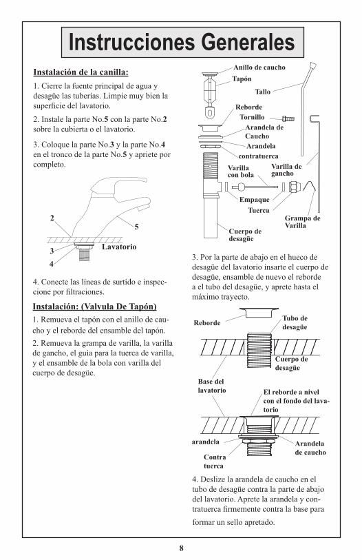
Instalación: (Valvula De Tapón)1. Remueva el tapón con el anillo de cau-cho y el reborde del ensamble del tapón. 2. Remueva la grampa de varilla, la varilla de gancho, el guia para la tuerca de varilla, y el ensamble de la bola con varilla del cuerpo de desagüe.
Grampa de Varilla
Tapón
Tuerca
Anillo de caucho
Tallo
TornilloArandela de Caucho
Reborde
Arandela
Empaque
Varilla de gancho
contratuercaVarilla con bola
Cuerpo de desagüe
3. Por la parte de abajo en el hueco de desagüe del lavatorio insarte el cuerpo de desagüe, ensamble de nuevo el reborde a el tubo del desagüe, y aprete hasta el máximo trayecto.
Reborde Tubo de desagüe
El reborde a nivel con el fondo del lava-torio
Arandela de caucho
arandela
Contra tuerca
Base del lavatorio
Cuerpo de desagüe
4. Deslize la arandela de caucho en el tubo de desagüe contra la parte de abajo del lavatorio. Aprete la arandela y con-tratuerca fi rmemente contra la base para formar un sello apretado.
Instalación de la canilla:1. Cierre la fuente principal de agua y desagüe las tuberías. Limpie muy bien la superfi cie del lavatorio.
2. Instale la parte No.5 con la parte No.2 sobre la cubierta o el lavatorio.
3. Coloque la parte No.3 y la parte No.4 en el tronco de la parte No.5 y apriete por completo.
4. Conecte las líneas de surtido e inspec-cione por fi ltraciones.
Lavatorio
5
34
2
Instrucciones Generales
5. Coloque de nuevo el tapón en el cuerpo de desagüe, con el anillo de caucho en su sitio y alinee el hueco del tapón con el guia y la avertura.
Tapón
Reborde
Alinee el hueco en el tapón con la avertura para el guia de Varilla (apuntado hacia la parte de atrás de la pared)
lavatorio
6. Insarte de nuevo el ensamble de la varilla con bola en el cuerpo de desagüe y a través del hueco del tapón.
7. Insarte el tallo del tapón a través del hueco en el cuerpo de la canilla. Una la varilla de gancho a el tallo para el tapón, insartando el tallo a través del hueco en la varilla del gancho; Arme de nuevo el guia de la va-rilla, la arandela y tuerca y aprete fi rmemente.
8. Ajuste el tallo del tapón a la altura correcta, abriendo el desagüe y deslizando la bola. Si es necesa-rio ajuste de nuevo el tornillo de la varilla de gancho, aprete a mano.
Emsamble de varilla con bola
Cuerpo de desagüe
Tallo del tapón
Guia de Va-rilla arande la y Tuerca Dibujo de
vista de lado de emsamble de Canilla y tapón
9. Haga las conecciones a la linea de surtido.
10. Abra el surtido de agua e inspeccione por fi ltraciones.
Cuerpo de desagüe
9
Instrucciones Generales
10
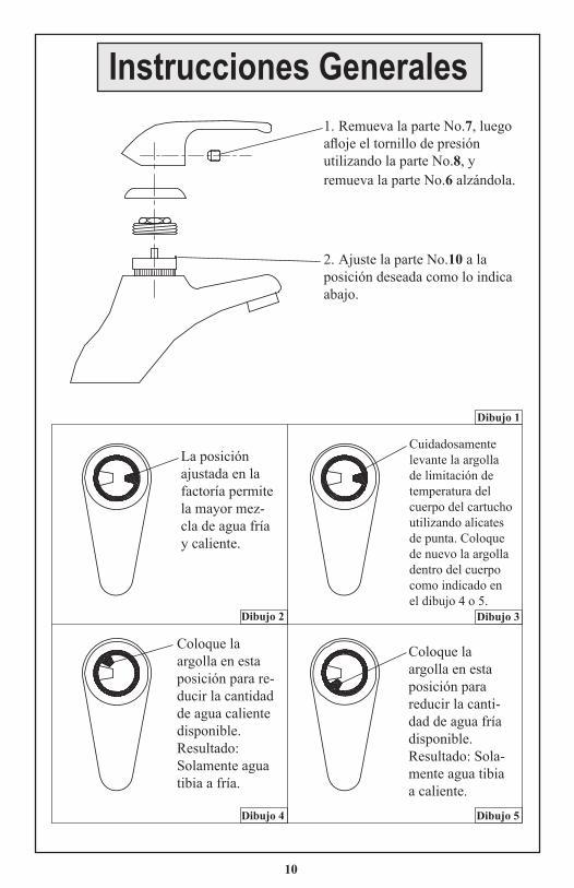
1. Remueva la parte No.7, luego afl oje el tornillo de presión utilizando la parte No.8, y remueva la parte No.6 alzándola.
2. Ajuste la parte No.10 a la posición deseada como lo indica abajo.
La posición ajustada en la factoría permite la mayor mez-cla de agua fría y caliente.
Cuidadosamente levante la argolla de limitación de temperatura del cuerpo del cartucho utilizando alicates de punta. Coloque de nuevo la argolla dentro del cuerpo como indicado en el dibujo 4 o 5.
Coloque la argolla en esta posición para re-ducir la cantidad de agua caliente disponible. Resultado: Solamente agua tibia a fría.
Coloque la argolla en esta posición para reducir la canti-dad de agua fría disponible.Resultado: Sola-mente agua tibia a caliente.
Dibujo 2 Dibujo 3
Dibujo 5Dibujo 4
Dibujo 1
Instrucciones Generales
Maintenance:1. To change no.10, remove no.7 by hand.2. Insert no.8 into hole of no.6 and loosen set screw of no.6. Remove no.6.3. Unscrew no.12 and remove.4. Unscrew no.11 and remove.5. Remove no.10 and replace with new no.10.6. Replace no.11, no.12 and no.6 and tighten set screw.7. Replace no.7.
Mantenimiento:1. Para cambiar la parte No.10, remueva a mano la parte No.7.2. Ensarte la parte No.8 en el hueco de la parte No.6 y afl oje el tornillo presión de la parte No.6. Remueva la parte No.6.3. Destornille la parte No.12 y remuévala.4. Destornille la parte No.11 y remuévala.5. Remueva la parte No.10 y reemplace con una parte nueva No.10.6. Reemplace la parte No.11, No.12 y la parte No.6. Apriete el tornillo de presión.7. Reemplace la parte No.7.
11
T&S BRASS AND BRONZE WORKS, INC. A fi rm commitment to application-engineered plumbing products
2 Saddleback Cove, P.O. Box 1088 T & S Brass-EuropeTravelers Rest, SC 29690 ‘De Veenhoeve’Phone: (864) 834-4102 Oude Nieuwveenseweg 84Fax: (864) 834-3518 2441 CW NieuwveenE-mail: [email protected] The Netherlands