H0561200A Installation and Operation Manual WARNING FOR YOUR SAFETY - This product must be installed and serviced by a professional pool/ spa service technician. The procedures in this manual must be followed exactly. Failure to follow warning notices and instructions may result in property damage, serious injury, or death. Installation and Operation Data JandyColors TM Digital Color Blending, Underwater Pool and Spa Lights
Transcript
H05
6120
0A
Installation and Op er a tion Man u al
WARNINGFOR YOUR SAFETY - This product must be installed and serviced by a pro fes sion al pool/spa service technician. The procedures in this manual must be followed ex act ly. Failure to follow warning notices and instructions may result in property damage, serious injury, or death.
Installation and Operation Data
JandyColorsTM
Digital Color Blending,Underwater Pool and Spa Lights
Page 3
Table of Contents
Section 1. Safety Information ................................................................................................................... 4
Section 2. Product Description and Model Numbers ............................................................................... 5
Section 3. Installing Jandy Light Fixture during New Construction ........................................................ 6
3.1 Preparing the Light Fixture for Installation ....................................................................... 63.2 Installing the Light Fixture ................................................................................................ 7
Section 4. Replacing Jandy Light Fixture in an Existing Pool or Spa ..................................................... 9
4.1 Preparing the Light Fixture for Replacement .................................................................... 94.2 Replacing the Light Fixture ............................................................................................... 9
Section 5. Wiring Options for Controlling Jandy Pool Lights or Jandy Spa Lights................................. 11
5.1 Wiring to an AquaLink® RS Control System .................................................................... 115.2 Wiring to a Time Clock ..................................................................................................... 12
Section 6. Jandy Pool Light and Jandy Spa Light Operating Instructions................................................ 13
6.1 To Operate the Light .......................................................................................................... 136.2 To Lock On a Specifi c Color Set ....................................................................................... 136.3 To Initiate a New Cycle or Reset from a Locked Color .................................................... 13
Section 8. Twelve (12) Volt Installation ................................................................................................... 17
Section 9. Exploded View and Replacement Parts ................................................................................... 18
9.1 Jandy Digital Pool Light ................................................................................................... 189.2 Jandy Digital Spa Light ..................................................................................................... 19
Page 4
Section 1. Safety Information
IMPORTANT SAFETY INSTRUCTIONS PERTAINING TO A RISK OF FIRE, ELECTRIC SHOCK, OR INJURY TO PERSONS
READ AND FOLLOW ALL INSTRUCTIONSWhen installing and using this electrical equipment, basic safety precautions should always be followed, including the following:
SAVE THESE INSTRUCTIONS
WARNINGRISK OF ELECTRICAL SHOCK OR ELECTROCUTION. This underwater light must be installed by a licensed or certified electrician in accordance with the National Electrical Code and applicable local codes and ordinances. Improper installation will create an electrical hazard, which could result in death or serious injury to pool or spa users, installers, or others due to electrical shock, and may also cause damage to property. Read and follow the specific instructions below.
WARNINGBefore installing this underwater light, read and follow all warning notices and instructions accompanying this light. Failure to follow safety warnings and instructions can result in severe injury, death, or property damage. Call (707) 776-8200 for additional free copies of these instructions.
ATTENTION INSTALLER: This manual contains important information about the installation, operation and safe use of this product. This information should be given to the owner/operator of this equipment.
NOTICEThese lights are intended for installation in fresh water swimming pools and spas only.
Page 5
Section 2. Product Description and Model Numbers
Product Voltage Cord Length Model #
Jandy Pool Light 12 Volt AC 30 feet JPL1230Jandy Pool Light 12 Volt AC 50 feet JPL1250Jandy Pool Light 12 Volt AC12 Volt AC 100 feet100 feet JPL12100JPL12100
Jandy Pool Light 120 Volt AC 30 feet JPL12030Jandy Pool Light 120 Volt AC 50 feet JPL12050Jandy Pool Light 120 Volt AC 100 feet JPL120100Jandy Pool Light 120 Volt AC 150 feet JPL120150
Jandy Spa Light 12 Volt AC 30 feet JSL1230Jandy Spa Light 12 Volt AC 50 feet JSL1250Jandy Spa Light 12 Volt AC 100 feet JSL 12100
Jandy Spa Light 120 Volt AC 30 feet JSL12030Jandy Spa Light 120 Volt AC 50 feet JSL12050Jandy Spa Light 120 Volt AC 100 feet JSL120100Jandy Spa Light 120 Volt AC 150 feet JSL120150
Page 6
Section 3. Installing Jandy Light Fixture during New Construction
3.1 Preparing the Light Fixture for Installation
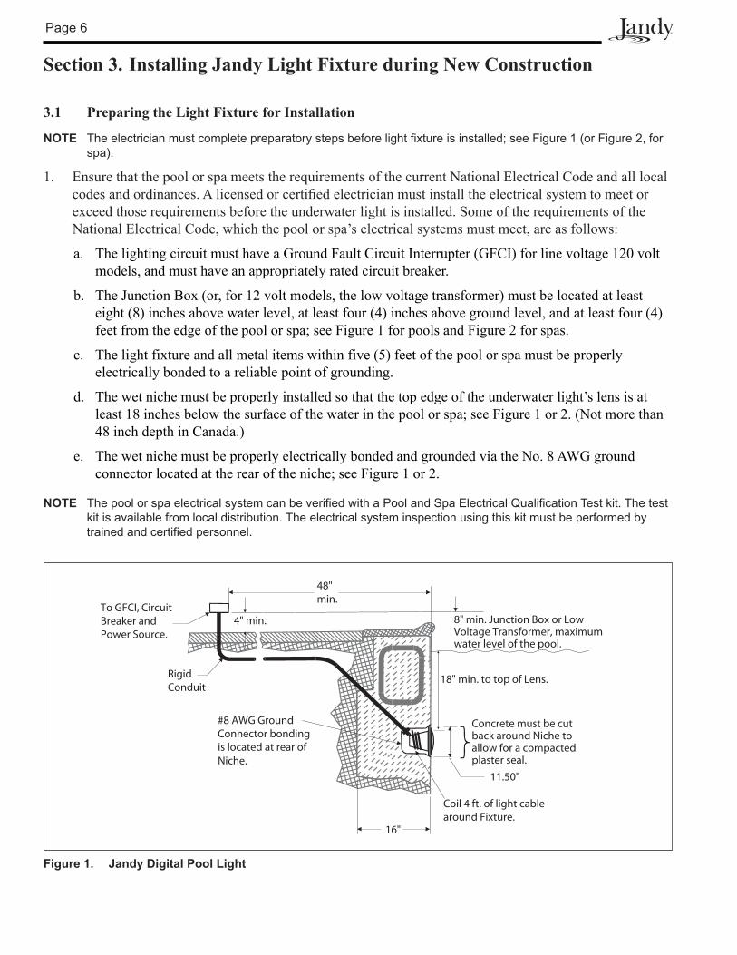
NOTE The electrician must complete preparatory steps before light fixture is installed; see Figure 1 (or Figure 2, for spa).
1. Ensure that the pool or spa meets the requirements of the current National Electrical Code and all local codes and ordinances. A licensed or certifi ed electrician must install the electrical system to meet or exceed those requirements before the underwater light is installed. Some of the requirements of the National Electrical Code, which the pool or spa’s electrical systems must meet, are as follows:
a.a. The lighting circuit must have a Ground Fault Circuit Interrupter (GFCI) for line voltage 120 volt The lighting circuit must have a Ground Fault Circuit Interrupter (GFCI) for line voltage 120 volt models, and must have an appropriately rated circuit breaker.models, and must have an appropriately rated circuit breaker.
b.b. The Junction Box (or, for 12 volt models, the low voltage transformer) must be located at least The Junction Box (or, for 12 volt models, the low voltage transformer) must be located at least eight (8) inches above water level, at least four (4) inches above ground level, and at least four (4) eight (8) inches above water level, at least four (4) inches above ground level, and at least four (4) feet from the edge of the pool or spa; see Figure 1 for pools and Figure 2 for spas.feet from the edge of the pool or spa; see Figure 1 for pools and Figure 2 for spas.
c.c. The light fixture and all metal items within five (5) feet of the pool or spa must be properly The light fixture and all metal items within five (5) feet of the pool or spa must be properly electrically bonded to a reliable point of grounding.electrically bonded to a reliable point of grounding.
d.d. The wet niche must be properly installed so that the top edge of the underwater light’s lens is at The wet niche must be properly installed so that the top edge of the underwater light’s lens is at least 18 inches below the surface of the water in the pool or spa; see Figure 1 or 2. (Not more than least 18 inches below the surface of the water in the pool or spa; see Figure 1 or 2. (Not more than 48 inch depth in Canada.)48 inch depth in Canada.)
e.e. The wet niche must be properly electrically bonded and grounded via the No. 8 AWG ground The wet niche must be properly electrically bonded and grounded via the No. 8 AWG ground connector located at the rear of the niche; see Figure 1 or 2.connector located at the rear of the niche; see Figure 1 or 2.
NOTE The pool or spa electrical system can be verified with a Pool and Spa Electrical Qualification Test kit. The test kit is available from local distribution. The electrical system inspection using this kit must be performed by trained and certified personnel.
Figure 1. Jandy Digital Pool Light
#8 AWG GroundConnector bondingis located at rear ofNiche.
RigidConduit
To GFCI, CircuitBreaker andPower Source.
4" min.
48"min.
8" min. Junction Box or Low Voltage Transformer, maximum water level of the pool.
18" min. to top of Lens.
Concrete must be cutback around Niche to allow for a compacted plaster seal.
Coil 4 ft. of light cablearound Fixture.
11.50"
16"
Page 7
2. To be certain that the pool or spa’s electrical system meets all applicable requirements, the electrician should also consult the local building department.
3. Use only approved wet niches (see following note) to ensure a safe and proper installation.
NOTE Jandy Pool and Spa Lights are ETL listed (ETL report/file 3033587.001) for installation with only the following manufacturer’s wet niche fixtures:
Large / Pool Type Niche Model Numbers:Pentair: 7821XXXX, 7822XXXX, 7823XXXX, 792067XX, 792089XXHayward DuraNiche: SP0600USta-Rite: 05161-XXXX, 05163-XXXX
Small / Spa Type Niche Model Numbers:Pentair: 7824XXXX, 792066XXHayward DuraNiche: SP0601USta-Rite: 05166-XXXX, 05167-XXXX
3.2 Installing the Light Fixture
NOTE Perform these steps only after the electrical system requirements are met.
1. Feed cord through conduit to Junction Box, leaving at least four (4) feet of cord at the light fi xture to coil around the light; see Figure 1 (or Figure 2, for spa). This four (4) feet of cord around the light allows the light to be serviced after the pool or spa is fi lled with water.
2. Cut the cord at the Junction Box, leaving at least six (6) inches of cord to make connections.
3. Strip six (6) inches of the outer cord jacket to expose the three insulated wires. Be careful not to damage the insulation on the three (3) inner wires.
4. Install strain relief over cord jacket and connect all three (3) wires to the corresponding circuit wires in the Junction Box. Install the Junction Box cover.
Figure 2. Jandy Digital Spa Light
WARNINGNever operate this underwater light for more than 10 seconds unless it is totally submerged in water. Without total submersion, the light assembly will get extremely hot, which may result in serious burns or in breakage of the bulb or lens. This may result in serious injury to pool or spa users, installers, or bystanders or in damage to property.
4" min.
48"min.
8" min. Junction Box orLow Voltage Transformer.
18" min. to top of Lens.
6.0"
Concrete must be cutback around Niche to allow for a compacted plaster seal.
Coil 4 ft. of light cablearound Fixture.
#8 AWG GroundConnector bondedto rebar.
RigidConduit
To GFCI, CircuitBreaker andPower Source.
Page 8
5. Coil the 4-foot length of cord around the fi xture and place the light assembly into the niche.
6. Engage the retainer tab on the bottom of the face ring, then pivot the top of the fi xture inward and tighten the special pilot screw.
WARNINGUse only the special pilot screw provided with this underwater light. This screw mounts and electrically grounds the housing securely to the mounting ring and wet niche. Failure to use the screw provided could create an electrical hazard, which could result in death or serious injury to pool or spa users, installers or others due to electrical shock.
7. Fill the pool or spa until the underwater light is completely submerged in water before operating the light for more than 10 seconds. Turn on main switch or circuit breaker, and the switch, which operates the underwater light, to check for proper operation. Refer to Section 6, Operating Instructions.
Page 9
Section 4. Replacing Jandy Light Fixture in an Existing Pool or Spa
WARNINGRisk of Electrical Shock or Electrocution. This underwater light must be installed by a licensed or certified electrician or a qualified pool or spa serviceman in accordance with the National Electrical Code and all applicable local codes and ordinances. Improper installation will create an electrical hazard, which could result in death or serious injury to pool or spa users, installers or others due to electrical shock, and may also cause damage to property.
Always disconnect the power to the pool or spa light at the circuit breaker before servicing the light. Failure to do so could result in death or serious injury to serviceman, pool or spa users or others due to electrical shock.
WARNINGFailure to bring the pool or spa’s electrical system up to code requirements before installing the underwater light will create an electrical hazard which could result in death or serious injury to pool or spa users, installers, or others due to electrical shock, and may also cause damage to property.
4.1 Preparing the Light Fixture for Replacement1. Verify that the pool or spa meets the requirements of the current National Electrical Code and all local
codes and ordinances. A licensed or certifi ed electrician must install the electrical system to meet or exceed those requirements before the underwater light is installed. Some of the requirements of the National Electrical Code, which the pool or spa’s electrical system must meet, are as follows:
a.a. The lighting circuit must have a Ground Fault Circuit Interrupter (GFCI) for line voltage 120 volt The lighting circuit must have a Ground Fault Circuit Interrupter (GFCI) for line voltage 120 volt models, and must have an appropriately rated circuit breaker.models, and must have an appropriately rated circuit breaker.
b.b. The Junction Box (or, for 12 volt models, the low voltage transformer) must be located at least The Junction Box (or, for 12 volt models, the low voltage transformer) must be located at least 8 inches above ground or water level, at least four (4) inches above ground level, and at least 48 8 inches above ground or water level, at least four (4) inches above ground level, and at least 48 inches from the edge of the pool or spa; see Figure 1 (or Figure 2, for spa).inches from the edge of the pool or spa; see Figure 1 (or Figure 2, for spa).
c.c. The light fixture and all metal items within 5 feet of the pool or spa must be properly electrically The light fixture and all metal items within 5 feet of the pool or spa must be properly electrically bonded to a reliable point of grounding.bonded to a reliable point of grounding.
d.d. The wet niche must be properly installed so that the top edge of the underwater light’s lens is at The wet niche must be properly installed so that the top edge of the underwater light’s lens is at least 18 inches below the surface of the water in the pool or spa; see Figure 1 (or Figure 2, for spa).least 18 inches below the surface of the water in the pool or spa; see Figure 1 (or Figure 2, for spa).
e.e. The wet niche must be properly electrically bonded and grounded via the No. 8 AWG ground The wet niche must be properly electrically bonded and grounded via the No. 8 AWG ground connector located at the rear of the niche; see Figure 1 (or Figure 2, for spa).connector located at the rear of the niche; see Figure 1 (or Figure 2, for spa).
NOTE The pool or spa electrical system can be verified with a Pool and Spa Electrical Qualification Test Kit. The test kit is available from local distribution. The electrical system inspection using this kit must be performed by trained and certified personnel.
2. To be certain that the pool or spa’s electrical system meets all applicable requirements, the electrician should also consult the local building department.
3. Use Jandy wet niches to ensure proper bonding and grounding connections.
4.2 Replacing the Light Fixture
NOTE Perform these steps only after the electrical system requirements are met.
Page 10
NOTE The light fixture may be replaced without removing water from the pool or spa.
1. Turn off the main electrical switch or circuit breaker, as well as the switch, which operates the underwater light.
2. To remove the light assembly, remove the special pilot screw at top of the face ring, remove the light assembly from the niche, and place the assembly on the deck.
WARNINGUse only the special pilot screw provided with this underwater light. This screw mounts and electrically grounds the housing securely to the mounting ring and wet niche. Failure to use the screw provided could create an electrical hazard, which could result in death or serious injury to pool or spa users, installers or others due to electrical shock.
WARNINGNever operate this underwater light for more than 10 seconds unless it is totally submerged in water. Without total submersion, the light assembly will get extremely hot, which may result in serious burns or in breakage of the bulb or lens. This may result in serious injury to pool or spa users, installers, or bystanders or in damage to property.
WARNINGBe sure to keep the special pilot screw from this underwater light. This screw mounts and electrically grounds the housing securely to the mounting ring and wet niche. Failure to use the screw provided could create an electrical hazard, which could result in death or serious injury to pool or spa users, installers or others due to electrical shock.
3. Remove Junction Box cover, disconnect the light fi xture wires and strain relief, and then pull the cord out of the conduit from the niche.
4. Feed the new light fi xture cord through the conduit from the niche to the Junction Box.
NOTE Depending on the length of the conduit, special tools may be required to pull the cord through the conduit.
5. Leave at least 4 feet of cord to coil around the light fi xture; see Figure 1 (or Figure 2, for spa). This allows the light to be serviced after the pool or spa is fi lled with water.
6. Cut the cord at the Junction Box, leaving at least 6 inches of cord to make connections.
7. Strip 6 inches of the outer cord jacket from the cord to expose the three insulated wires. Be careful not to damage the insulation on the three inner wires.
8. Install the strain relief over the cord jacket and connect all three wires to the corresponding circuit wires in the Junction Box, black wire to power, white wire to common, and green wire to ground. Install the Junction Box cover.
9. Replace light assembly into the niche and tighten the special pilot screw.
10. Fill the pool or spa until the underwater light is completely submerged in water before operating the light for more than 10 seconds. Turn on main switch or circuit breaker, as well as the switch, which operates the underwater light, to check for proper operation. Refer to Section 6, Operating Instructions.
Page 11
Section 5. Wiring Options for Controlling Jandy Pool Lights or Jandy Spa Lights
NOTE The Jandy Pool and Spa Lights will not operate properly with light dimmers. Do not wire the Jandy Lights to any dimming circuitry.
To the extent allowed by code and capacity of the electrical equipment, multiple To the extent allowed by code and capacity of the electrical equipment, multiple Jandy Pool and Spa Jandy Pool and Spa LightsLights may be controlled with a single switch so their colors will may be controlled with a single switch so their colors will alwaysalways be synchronized. be synchronized.
Separate switches may be used to control the on/off and color functions of each Separate switches may be used to control the on/off and color functions of each Jandy Pool or Spa LightJandy Pool or Spa Light. . It is recommended that these switches be located next to each other to facilitate simple color synchronization It is recommended that these switches be located next to each other to facilitate simple color synchronization when desired. All switches when desired. All switches must be operated at the same time to assure color synchronizationmust be operated at the same time to assure color synchronization otherwise the otherwise the lights will work independently of each other.lights will work independently of each other.
5.1 Wiring to an AquaLink® RS Control System
The Jandy Pool and Spa Lights can be wired into the Jandy AquaLink RS control system to ensure simplifi ed operation of the lights, as well as a means to synchronize the color change function. Connect the lights to one of the auxiliary relays in the Power Center.
NOTE It is recommended to connect one light per relay so each light can be controlled separately. However, up to four lights can be connected on a single relay. If there are more than four lights installed on one AquaLink RS system, ensure there is more than one auxiliary relay available in the Power Center.
Refer to Figures 3 and 4 to connect the Jandy Pool and Spa Lights to the Power Center.
GFCIBlack
White
Green
120VJandy Light
Ground
Ground
Neutral
120 VACPower Supply
Figure 3. 120-Volt Jandy Pool and Spa Light Wiring Diagram
CAUTIONA Ground Fault Circuit Interrupter (GFCI) must be provided in this circuit. The conductors on the load side of the GFCI circuit shall not occupy conduit, boxes, or enclosures containing other conductors unless the additional conductors are also protected by a GFCI. Refer to local codes for complete details.
Page 12
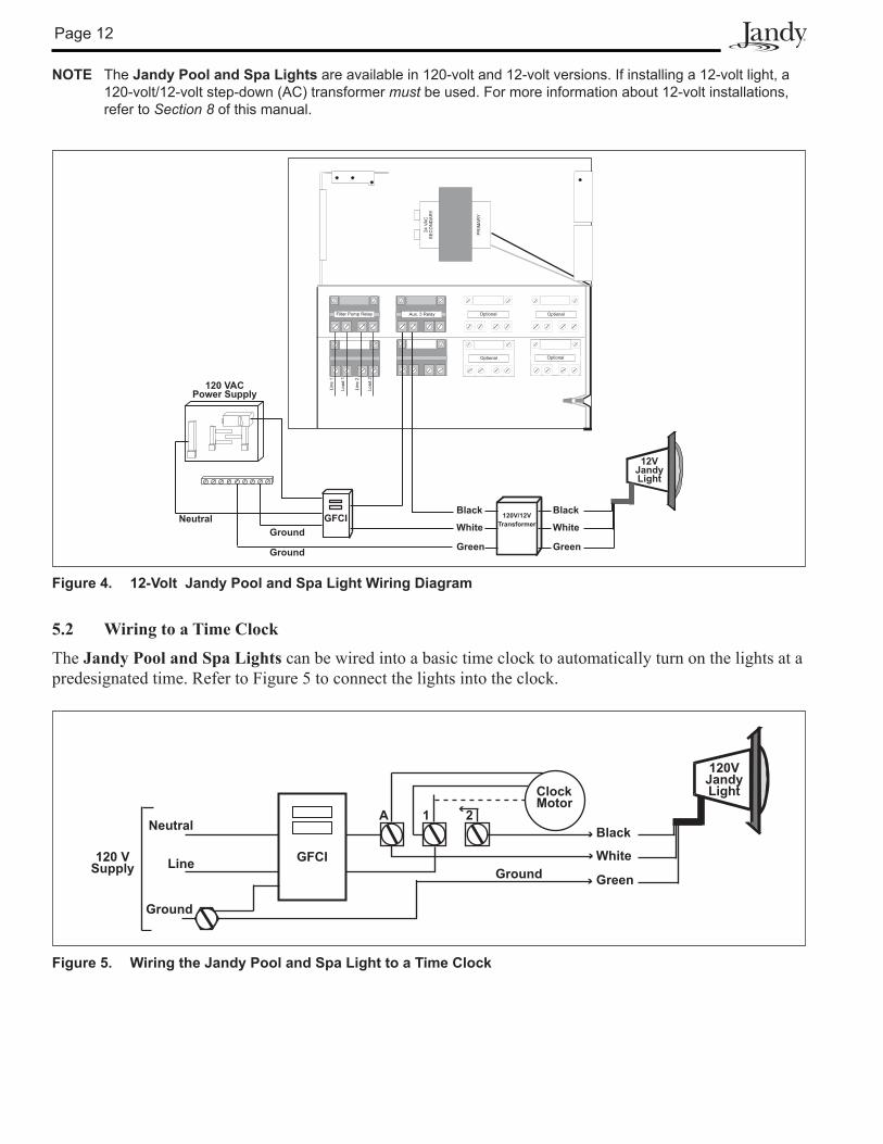
NOTE The Jandy Pool and Spa Lights are available in 120-volt and 12-volt versions. If installing a 12-volt light, a 120-volt/12-volt step-down (AC) transformer must be used. For more information about 12-volt installations, refer to Section 8 of this manual.
Figure 4. 12-Volt Jandy Pool and Spa Light Wiring Diagram
GFCI
Ground
Ground
NeutralBlack
White
Green
12VJandy Light
Black
White
Green
120V/12V
Transformer
120 VACPower Supply
5.2 Wiring to a Time Clock
The Jandy Pool and Spa Lights can be wired into a basic time clock to automatically turn on the lights at a predesignated time. Refer to Figure 5 to connect the lights into the clock.
Figure 5. Wiring the Jandy Pool and Spa Light to a Time Clock
Clock Motor
Ground
Ground
Neutral
Line120 V
Supply
A 1 2
Black
White
Green
120VJandyLight
GFCI
Page 13
Section 6. Jandy Pool Light and Jandy Spa Light Operating Instructions
6.1 To Operate the Light
Turn the light ON. The fi rst time the light is turned on, the color change sequence begins with the Alpine White color set and then continues through the sequence. The light cycles through 10 color set changes. Each color set is active for approximately 20 seconds before the light transitions to the next color (see Table 1).
Table 1. Pool and Spa Lights Color Change Sequence
Sequence Order Color Set (Consists of Two Colors in Each Light)1 Alpine White (first cycle only)
10 Violet (color remains active approximately 4 minutes)
NOTE When the light is first turned on, the sequence ends at Violet and at the next rotation, starts at Sky Blue. Alpine White is not included in subsequent cycles.
When the light is turned off, it will remain in the color set that is currently active. When the light is turned back on, the color change sequence will start with the color set that was last active. For example, if the light is turned off when Cobalt Blue color set is active, then Cobalt Blue will be the first color set in the change sequence when the light is turned on again.
6.2 To Lock On a Specifi c Color Set
Wait until the desired color is ON during the fi rst cycle of color change. Turn the light OFF, wait 2seconds and then turn the light back ON. Wait 10 seconds before turning the light off so that the color will not reset.
NOTE If a specific color is not locked on during first cycle of colors, the light will continue to follow the color change sequence. To choose a color after the first cycle, the light must be reset.
If you encounter a dimmed light, the light was probably turned off during in the middle of the color transition. To resolve this situation, turn the light off for 3 seconds, then turn it back on. The light will return to full power.
6.3 To Initiate a New Cycle or Reset from a Locked Color
Turn the light OFF, wait 2 seconds, then turn ON, wait 2 seconds, then turn OFF, wait 2 seconds, and then turn ON again. The light will return to beginning of the color cycle (Alpine White) and continue with the normal light sequence (see Table 1 in Section 6.1).
NOTE To synchronize colors on multiple Jandy Pool and Spa Light systems wired to separate switches, perform the above actions on all of their switches simultaneously. All Jandy Digital Pool and Spa Lights will synchronize automatically if activated off of the same switch. No other accessories are required.
Page 14
Section 7. Replacing Bulbs
WARNINGAlways disconnect power to the pool or spa light at the circuit breaker before servicing the light. Failure to do so could result in death or serious injury to installer, serviceman, pool or spa users or others due to electrical shock.
WARNINGReplace all bulbs with bulbs of the same type and wattage. Failure to replace the bulbs with those of the same type will damage the light assembly and may cause an electrical hazard resulting in death or serious injury to pool or spa users, installers, or others due to electrical shock, and may also cause damage to property. Be sure the power is switched OFF before removing or installing bulbs. Allow bulbs to cool before replacing. This light fixture uses quartz halogen bulbs. Hold bulbs on the outside only. DO NOT touch the bulb or surface with bare hands; doing so could severely reduce bulb life.
WARNINGBe sure to keep the special pilot screw from this underwater light. This screw mounts and electrically grounds the housing securely to the mounting ring and wet niche. Failure to use the screw provided could create an electrical hazard, which could result in death or serious injury to pool or spa users, installers or others due to electrical shock.
1. Turn off the main electrical switch or circuit breaker, as well as the switch, which operates the underwater light.
2. Be sure to have the following items:
• A new lens gasket (P/N R0399800 for Jandy Pool Light and P/N R0400500 for Jandy Spa Light).
• Eight (8) new bulbs. See Table 2 for bulb specifi cation.
Table 2. Bulb Specifi cations
Model Number Fixture Voltage
Bulb Voltage
Bulb Wattage
Halogen BulbType
Qty. per Fixture
Bulb KitPart
Number(2 bulbs per kit)
JANDY POOL LIGHT 120 Volt AC 12 Volt 75 Watt MR-16 EYC 8 R0399600
JANDY POOL LIGHT 12 Volt AC 12 Volt 75 Watt MR-16 EYC 8 R0399600
JANDY SPA LIGHT 120 Volt AC 12 Volt 25 Watt Capsule (G-4) 8 R0400300
JANDY SPA LIGHT 12 Volt AC 12 Volt 25 Watt Capsule (G-4) 8 R0400300
NOTE Both 120V and 12V Jandy Pool and Spa Lights use 12V Halogen bulbs.
3. To remove the light assembly, remove the special pilot screw at the top of the face ring, remove light assembly from niche and gently place assembly on the deck. It is not necessary to drain down the pool or spa (see Figure 6).
Page 15
4. Disassemble the light fi xture and replace bulbs. Use the following bulb removal instructions for Jandy Pool and Spa Light:
a.a. Loosen the Phillips head screw on the band clamp to allow the clamp to be removed. Screw should Loosen the Phillips head screw on the band clamp to allow the clamp to be removed. Screw should be loosened, but not removed to prevent loss of parts and ease of assembly.be loosened, but not removed to prevent loss of parts and ease of assembly.
b.b. Remove the band clamp, bezel face ring, glass lens and gasket from the housing. Remove the Remove the band clamp, bezel face ring, glass lens and gasket from the housing. Remove the gasket from the lens. Refer to gasket from the lens. Refer to Section 9, Exploded Views and Replacement PartsSection 9, Exploded Views and Replacement Parts..
c.c. Remove the two Phillips hex head Dichroic Lens holder Plate retaining screws.Remove the two Phillips hex head Dichroic Lens holder Plate retaining screws.
d.d. Carefully remove the Dichroic Lens Plate. The eight bulbs can now be removed. Discard the Carefully remove the Dichroic Lens Plate. The eight bulbs can now be removed. Discard the bulbs.bulbs.
e.e. Install eight new bulbs (four (4) sets of P/N R0399600 for Install eight new bulbs (four (4) sets of P/N R0399600 for Jandy Pool LightJandy Pool Light or four (4) sets of or four (4) sets of P/N R0400300 for P/N R0400300 for Jandy Spa LightJandy Spa Light). Do not touch the bulb surface with bare hands, as this can ). Do not touch the bulb surface with bare hands, as this can dramatically reduce bulb life. Repeat procedure for each bulb.dramatically reduce bulb life. Repeat procedure for each bulb.
f.f. Re-position the Lens Plate over the bulbs.Re-position the Lens Plate over the bulbs.
g.g. Install the two Lens Plate retaining screws. Do not over-tighten.Install the two Lens Plate retaining screws. Do not over-tighten.
Power Cord
Niche
Spa Light Assembly
Spa Wall
Mounting Screw
Positioning Tab
Tab Locator
2 Push up on bottom of light assembly.
1 Pull top of light assembly away from spa wall.
Figure 6. Removing the Light Assembly for Bulb Replacement
WARNINGRisk of Electrical Shock or Electrocution. Always install a new lens gasket whenever disassembling the light (for Jandy Pool Light Gasket P/N R0399800 and for Jandy Spa Light Gasket P/N R0400500). Failure to do so may permit water to leak into the assembly, which could cause:
(a) An electrical hazard resulting in death or serious injury to pool or spa users, installers, or others due to electrical shock, or
(b) Breakage of the bulb or lens, which likewise could result in serious injury to pool or spa users, installers, or bystanders, or in damage to property.
Page 16
5. Reassemble the fi xture (applies to both Jandy Pool Light and Jandy Spa Light).
a.a. If not already done, remove the gasket from the glass lens and install a new gasket, If not already done, remove the gasket from the glass lens and install a new gasket, Jandy Pool Jandy Pool LightLight Gasket Gasket (P/N R0399800) and (P/N R0399800) and Jandy Spa Light GasketJandy Spa Light Gasket (P/N R0400500), on the lens. (P/N R0400500), on the lens.
NOTE A new lens gasket must be used each time the light is reassembled.
b.b. While holding the fixture upright, place the glass lens with gasket and bezel face ring on top of the While holding the fixture upright, place the glass lens with gasket and bezel face ring on top of the light shell. Align the pilot screw in the bezel face ring with the arrow located on the housing label light shell. Align the pilot screw in the bezel face ring with the arrow located on the housing label marked “Arrow on this label must line up with the pilot screw on the face ring”. Make sure lens is marked “Arrow on this label must line up with the pilot screw on the face ring”. Make sure lens is properly aligned as well, with the letter “O” in Top aligned directly with the bezel face ring pilot properly aligned as well, with the letter “O” in Top aligned directly with the bezel face ring pilot screw and the can label previously described.screw and the can label previously described.
c.c. While holding the aligned face ring and shell together turn the assembly upside down and set it While holding the aligned face ring and shell together turn the assembly upside down and set it on the old gasket, using the old gasket as an assembly fixture. This will keep the lens and gasket on the old gasket, using the old gasket as an assembly fixture. This will keep the lens and gasket assembly from being pushed out of the face ring while you secure it to the light fixture.assembly from being pushed out of the face ring while you secure it to the light fixture.
d.d. With the clamp bolt flange pointing to the side, spread the clamp and place it around the face ring, With the clamp bolt flange pointing to the side, spread the clamp and place it around the face ring, gasket and housing flange as shown in the exploded view in gasket and housing flange as shown in the exploded view in Section 9Section 9. Check to see that the clamp . Check to see that the clamp is properly installed around the entire flange. It is important to have the screw already started in is properly installed around the entire flange. It is important to have the screw already started in the clamp retaining swivel nut as it makes installation much easier.the clamp retaining swivel nut as it makes installation much easier.
e.e. In the event the clamp screw is not already in the clamp retaining swivel nut, hold the ends of the In the event the clamp screw is not already in the clamp retaining swivel nut, hold the ends of the clamp together. Insert the bolt through the open side and thread it into the round swivel nut. Using a clamp together. Insert the bolt through the open side and thread it into the round swivel nut. Using a Phillips head screwdriver, tighten the screw until the distance between the ends of the clamp equals Phillips head screwdriver, tighten the screw until the distance between the ends of the clamp equals ¼ inch or less. ¼ inch or less.
f.f. Discard the old gasket.Discard the old gasket.
6. Reinstall the Jandy Light into niche fi xture.
a.a. Coil the extra cord around the fixture and place the light assembly into the niche.Coil the extra cord around the fixture and place the light assembly into the niche.
b.b. Engage the retainer tab on the bottom of the face ring, then pivot the top of the fixture inward and Engage the retainer tab on the bottom of the face ring, then pivot the top of the fixture inward and tighten the special pilot screw. tighten the special pilot screw.
WARNINGNever operate this underwater light for more than 10 seconds unless it is totally submerged in water. Without total submersion, the light assembly will get extremely hot, which may result in serious burns or in breakage of the bulb or lens. This may result in serious injury to pool or spa users, installers, or bystanders or in damage to property.
WARNINGUse only the special pilot screw provided with this underwater light. This screw mounts and electrically grounds the housing securely to the mounting ring and wet niche. Failure to use the screw provided could create an electrical hazard, which could result in death or serious injury to pool or spa users, installers or others due to electrical shock.
7. If pool or spa is empty, fi ll pool or spa until the underwater light is completely submerged in water before operating the light for more than 10 seconds. Turn on main switch or circuit breaker, as well as the switch, which specifi cally operates the underwater light, to check for proper operation.
Page 17
Section 8. Twelve (12) Volt Installation
A separate 12-Volt AC Transformer is required on all 12-Volt Models--For Jandy Pool Light use a 300-watt multi tap 12-volt system. For the Jandy Spa Light, a 100 watt 12-volt system is acceptable. To ensure maximum safety, it is strongly recommended that a transformer that has been listed or recognized by a Nationally Recognized Testing Laboratory (NRTL) for the application be used.
NOTE Jandy does not recommend installing 12-volt lights with cord lengths greater than 50 feet. A significant voltage drop will occur that dramatically reduces the light output and possibly unit failure. Wires from Transformer to Junction Box can reduce voltage and brilliance in addition to losses in the12 gauge 12-volt cord. Refer to chart below for wire voltage losses and potential effect.
DWG# Part# Description Field Replaceable1 N/A Pool Light Housing NO - Purchase New Light2 N/A Transformer (120 Volt lights only)-Pool NO - Purchase New Light3 N/A Bulb Holder and Electronics Assembly-Pool NO - Purchase New Light4 R0399600 Bulb Kit: 75 Watt Halogen MR-16 EYC
Figure 8. Three Dimensional View from Back Side Figure 9. Cross Section of Jandy Pool Light
Page 19
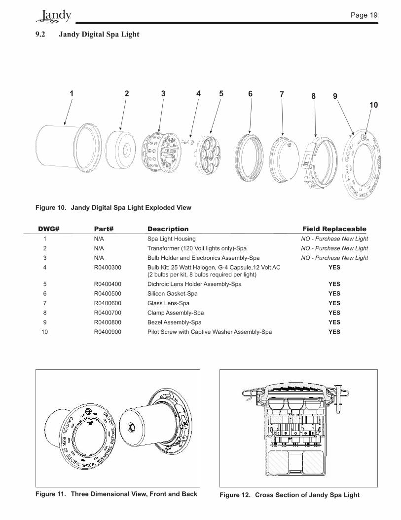
9.2 Jandy Digital Spa Light
1 2 3 4 5 6 7 8 910
Figure 10. Jandy Digital Spa Light Exploded View
DWG# Part# Description Field Replaceable1 N/A Spa Light Housing NO - Purchase New Light2 N/A Transformer (120 Volt lights only)-Spa NO - Purchase New Light3 N/A Bulb Holder and Electronics Assembly-Spa NO - Purchase New Light4 R0400300 Bulb Kit: 25 Watt Halogen, G-4 Capsule,12 Volt AC