26
Installation- and Operating instructions for CU8810-0000 DVI Splitter for CP69xx and CP79xx Version: 1.2 Date: 2016-01-21

Installation- and Operating instructions for
CU8810-0000 DVI Splitter for CP69xx and CP79xx Version: 1.2 Date: 2016-01-21


Table of contents
Table of contents 1 Foreword 3
1.1 Notes on the Documentation 3 1.1.1 Liability Conditions 3 1.1.2 Trademarks 3 1.1.3 Patent Pending 3 1.1.4 Copyright 3 1.1.5 State at Delivery 3 1.1.6 Delivery conditions 3
1.2 Description of safety symbols 4 1.3 Operator’s obligation to exercise diligence 4
2 Product Description 5 2.1 Product Overview 5 2.2 Connections 6
2.2.1 Power Supply (X10) 6 2.2.2 Data Connectors 6
2.3 LED-Diagnostics 8
3 Installation 9 3.1 Transport and Unpacking 9
3.1.1 Transport 9 3.1.2 Unpacking 9
3.2 Mounting / Unmounting 10 3.2.1 Mounting the DVI Splitter 10 3.2.2 Unmounting the DVI Splitter 10
3.3 Connecting devices 11 3.3.1 Connecting cables 11 3.3.2 Connecting Power Supply 11
4 Operation 12 4.1 Configuration 12
4.1.1 Opening the enclosure 12 4.1.2 DIP Switch 1 (SW1) 13 4.1.3 DIP Switch 2 (SW2) 15 4.1.4 DIP-Switch 3 (SW3) 16
4.2 Architecture Description 18 4.2.1 Version 1 18 4.2.2 Version 2 18 4.2.3 Version 3 18
CU8810-0000 1
Table of contents
4.2.4 Version 4 19 4.3 Maintenance 20
4.3.1 Cleaning 20 4.3.2 Maintenance 20
4.4 Shutting down 20 4.4.1 Disposal 20
5 Dimensions 21
6 Technical Data 22
7 Appendix 23 7.1 Beckhoff Support and Service 23
7.1.1 Beckhoff branches and partner companies 23 7.1.2 Beckhoff company headquarters 23
7.2 Approvals for USA and Canada 24 7.3 FCC Approval for USA 24 7.4 FCC Approval for Canada 24
2 CU8810-0000

Foreword
1 Foreword
1.1 Notes on the Documentation This description is only intended for the use of trained specialists in control and automation engineering who are familiar with the applicable national standards. It is essential that the following notes and explanations are followed when installing and commissioning these components.
The responsible staff must ensure that the application or use of the products described satisfy all the requirements for safety, including all the relevant laws, regulations, guidelines and standards.
1.1.1 Liability Conditions
The documentation has been prepared with care. The products described are, however, constantly under development. For that reason the documentation is not in every case checked for consistency with performance data, standards or other characteristics. In the event that it contains technical or editorial errors, we retain the right to make alterations at any time and without warning. No claims for the modification of products that have already been supplied may be made on the basis of the data, diagrams and descriptions in this documentation.
All pictures shown in the documentation are exemplary. Illustrated configurations can differ from standard.
1.1.2 Trademarks
Beckhoff®, TwinCAT®, EtherCAT®, Safety over EtherCAT®, TwinSAFE® and XFC® are registered trademarks of and licensed by Beckhoff Automation GmbH. Other designations used in this publication may be trademarks whose use by third parties for their own purposes could violate the rights of the owners.
1.1.3 Patent Pending
The EtherCAT Technology is covered, including but not limited to the following patent applications and patents: EP1590927, EP1789857, DE102004044764, DE102007017835 with corresponding applications or registrations in various other countries. The TwinCAT Technology is covered, including but not limited to the following patent applications and patents: EP0851348, US6167425 with corresponding applications or registrations in various other countries.
1.1.4 Copyright © Beckhoff Automation GmbH & Co. KG. The reproduction, distribution and utilization of this document as well as the communication of its contents to others without express authorization are prohibited. Offenders will be held liable for the payment of damages. All rights reserved in the event of the grant of a patent, utility model or design.
1.1.5 State at Delivery All the components are supplied in particular hardware and software configurations appropriate for the application. Modifications to hardware or software configurations other than those described in the documentation are not permitted, and nullify the liability of Beckhoff Automation GmbH & Co. KG.
1.1.6 Delivery conditions
In addition, the general delivery conditions of the company Beckhoff Automation GmbH & Co. KG apply.
CU8810-0000 3
Foreword
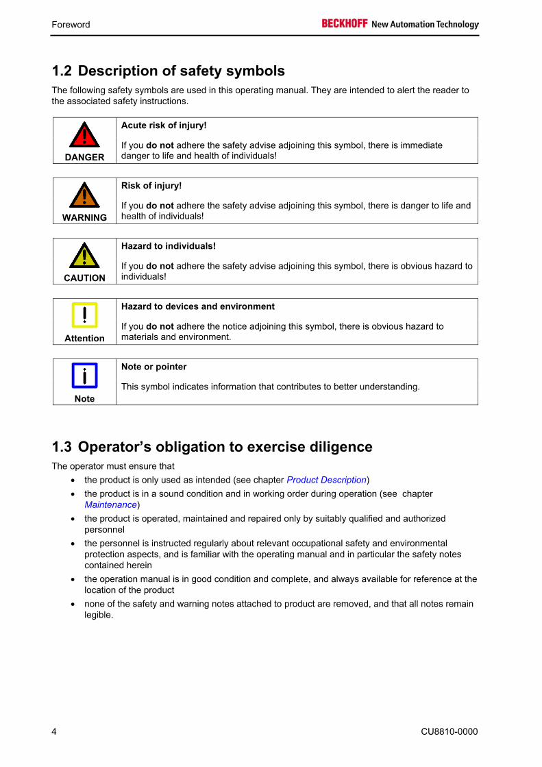
1.2 Description of safety symbols The following safety symbols are used in this operating manual. They are intended to alert the reader to the associated safety instructions.
Acute risk of injury!
DANGER
If you do not adhere the safety advise adjoining this symbol, there is immediate danger to life and health of individuals!
Risk of injury!
WARNING
If you do not adhere the safety advise adjoining this symbol, there is danger to life and health of individuals!
Hazard to individuals!
CAUTION
If you do not adhere the safety advise adjoining this symbol, there is obvious hazard to individuals!
Hazard to devices and environment
Attention
If you do not adhere the notice adjoining this symbol, there is obvious hazard to materials and environment.
Note or pointer
Note
This symbol indicates information that contributes to better understanding.
1.3 Operator’s obligation to exercise diligence The operator must ensure that
• the product is only used as intended (see chapter Product Description) • the product is in a sound condition and in working order during operation (see chapter
Maintenance) • the product is operated, maintained and repaired only by suitably qualified and authorized
personnel • the personnel is instructed regularly about relevant occupational safety and environmental
protection aspects, and is familiar with the operating manual and in particular the safety notes contained herein
• the operation manual is in good condition and complete, and always available for reference at the location of the product
• none of the safety and warning notes attached to product are removed, and that all notes remain legible.
4 CU8810-0000

Product Description
2 Product Description
2.1 Product Overview
A common application in machine and plant construction is the simultaneous display of a PC screen on several monitors. Up to four DVI/USB Control Panels can be connected to a PC via the CU8810-0000 DVI Splitter. Thanks to DVI/USB extension technology, the Control Panels can each be connected at distances of 50 m from the DVI Splitter. PCs with two DVI outputs, which are configured as extended desktops, generate two different screen contents. Both DVI outputs can be fed into the DVI Splitter. Using DIP switches, the four DVI outputs can each be assigned to one of the two DVI inputs, so that the Control Panels show either the left or the right half of the desktop, as selected.
Other outstanding features are:
• metal housing for DIN rail installation
• compact industrial design
• 2 DVI-D inputs, 4 DVI-D outputs
• assignment of the 4 DVI outputs to the 2 inputs freely configurable via DIP switches
• DVI inputs and outputs with full DVI data range up to 1.65 Gbit/s
• unused DVI input and outputs can be switched off to save energy
• 4-port USB hub with 4 USB Extended outputs as RJ 45 connectors
• USB transfer rate up to 12 Mbit/s for USB 1.1, downwards compatible to USB 1.0
• 24 V DC power supply.
CU8810-0000 5
Product Description
2.2 Connections
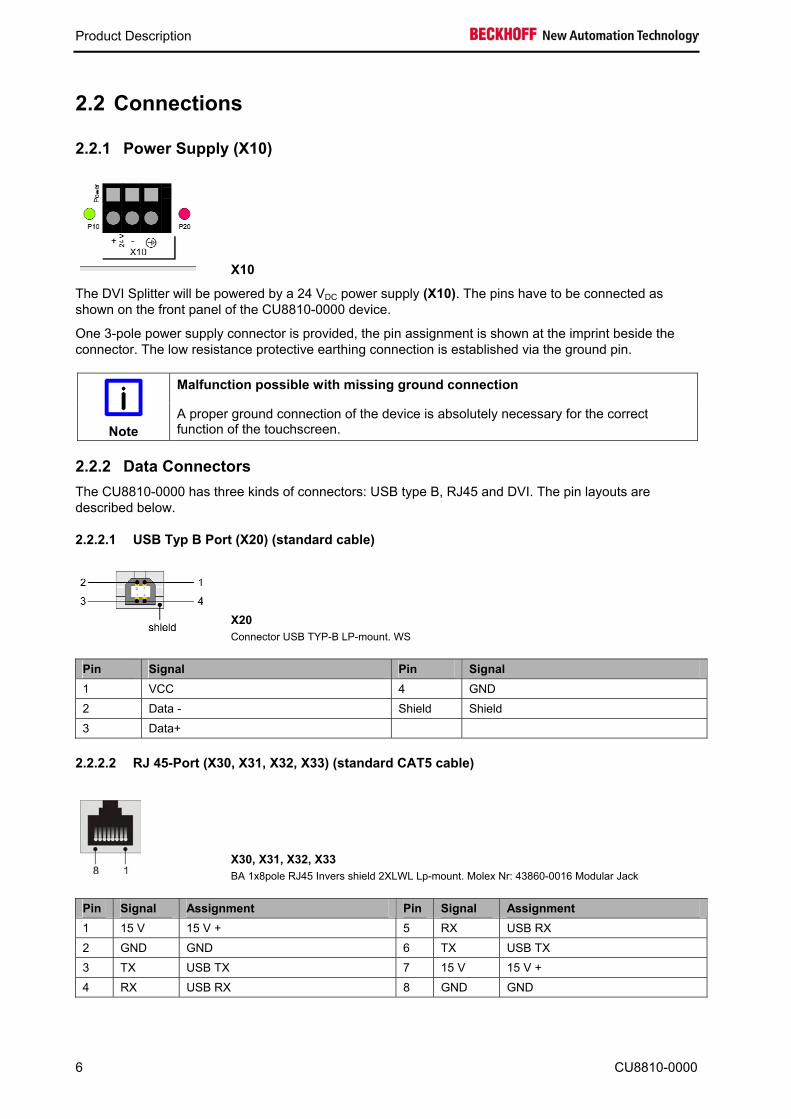
2.2.1 Power Supply (X10)
X10
The DVI Splitter will be powered by a 24 VDC power supply (X10). The pins have to be connected as shown on the front panel of the CU8810-0000 device.
One 3-pole power supply connector is provided, the pin assignment is shown at the imprint beside the connector. The low resistance protective earthing connection is established via the ground pin.
Malfunction possible with missing ground connection
Note
A proper ground connection of the device is absolutely necessary for the correct function of the touchscreen.
2.2.2 Data Connectors The CU8810-0000 has three kinds of connectors: USB type B, RJ45 and DVI. The pin layouts are described below.
2.2.2.1 USB Typ B Port (X20) (standard cable)
X20 Connector USB TYP-B LP-mount. WS
Pin Signal Pin Signal 1 VCC 4 GND 2 Data - Shield Shield 3 Data+
2.2.2.2 RJ 45-Port (X30, X31, X32, X33) (standard CAT5 cable)
X30, X31, X32, X33 BA 1x8pole RJ45 Invers shield 2XLWL Lp-mount. Molex Nr: 43860-0016 Modular Jack
Pin Signal Assignment Pin Signal Assignment 1 15 V 15 V + 5 RX USB RX 2 GND GND 6 TX USB TX 3 TX USB TX 7 15 V 15 V + 4 RX USB RX 8 GND GND
6 CU8810-0000

Product Description
2.2.2.3 DVI Input (DVI-IN X40, X41) (standard DVI cable)
X40, X41 Connector DVI-D 3x8pole Digital LP-mount.
Pin Signal Pin Signal 1 TMDS Data 2- 13 n.c. 2 TMDS Data 2+ 14 + 5 V Power Supply 3 TMDS Data2/4 Shield 15 GND ( +5 V, Analog H/V Sync) 4 n.c. 16 Hot Plug Detect 5 n.c. 17 TMDS Data 0 - 6 DDC Clock 18 TMDS Data 0 + 7 DDC Data 19 TMDS Data 0/5 Shield 8 Analog Vertical Sync 20 n.c. 9 TMDS Data 1 - 21 n.c. 10 TMDS Data 1 + 22 TMDS Clock Shield 11 TMDS Data1/3 Shield 23 TMDS Clock + 12 n.c. 24 TMDS Clock -
2.2.2.4 DVI Output (DVI-OUT X50, X51, X52, X53) (standard DVI cable)
X50, X51, X52, X53 Connector DVI-D 3x8pole Digital LP-mount.
Pin Signal Pin Signal 1 TMDS Data 2- 13 n.c. 2 TMDS Data 2+ 14 + 5 V Power Supply 3 TMDS Data2/4 Shield 15 GND ( +5 V, Analog H/V Sync) 4 n.c. 16 Hot Plug Detect 5 n.c. 17 TMDS Data 0 - 6 DDC Clock 18 TMDS Data 0 + 7 DDC Data 19 TMDS Data 0/5 Shield 8 Analog Vertical Sync 20 n.c. 9 TMDS Data 1 - 21 n.c. 10 TMDS Data 1 + 22 TMDS Clock Shield 11 TMDS Data1/3 Shield 23 TMDS Clock + 12 n.c. 24 TMDS Clock -
CU8810-0000 7
Product Description
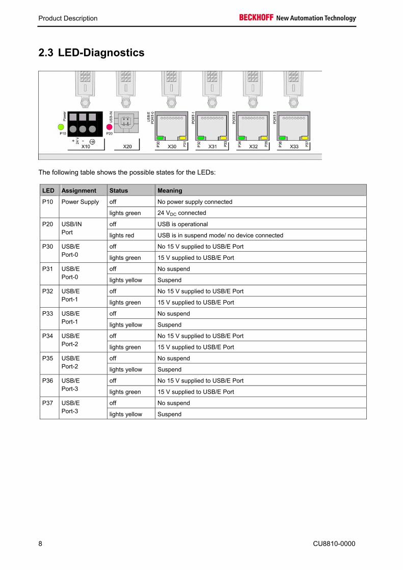
2.3 LED-Diagnostics
The following table shows the possible states for the LEDs:
LED Assignment Status Meaning
off No power supply connected P10 Power Supply
lights green 24 VDC connected
off USB is operational P20 USB/IN Port lights red USB is in suspend mode/ no device connected
off No 15 V supplied to USB/E Port P30 USB/E Port-0 lights green 15 V supplied to USB/E Port
off No suspend P31 USB/E Port-0 lights yellow Suspend
off No 15 V supplied to USB/E Port P32 USB/E Port-1 lights green 15 V supplied to USB/E Port
off No suspend P33 USB/E Port-1 lights yellow Suspend
off No 15 V supplied to USB/E Port P34 USB/E Port-2 lights green 15 V supplied to USB/E Port
off No suspend P35 USB/E Port-2 lights yellow Suspend
off No 15 V supplied to USB/E Port P36 USB/E Port-3 lights green 15 V supplied to USB/E Port
off No suspend P37 USB/E Port-3 lights yellow Suspend
8 CU8810-0000
Installation
3 Installation
3.1 Transport and Unpacking The specified storage conditions must be observed (see chapter Technical Data).
3.1.1 Transport Despite the robust design of the unit, the components are sensitive to strong vibrations and impacts. During transport, the unit should therefore be protected from excessive mechanical stress. Therefore, please use the original packaging.
Danger of damage to the unit
Attention
If the device is transported in cold weather or is exposed to extreme variations in temperature, make sure that moisture (condensation) does not form on or inside the device.
Prior to operation, the unit must be allowed to slowly adjust to room temperature. Should condensation occur, a delay time of approximately 12 hours must be allowed before the unit is switched on.
3.1.2 Unpacking Proceed as follows to unpack the unit:
1. Remove packaging
2. Do not discard the original packaging. Keep it for future relocation
3. Check the delivery for completeness by comparing it with your order
4. Please keep the associated paperwork. It contains important information for handling the unit
5. Check the contents for visible shipping damage.
If you notice any shipping damage or inconsistencies between the contents and your order, you should notify Beckhoff Service.
CU8810-0000 9

Installation
3.2 Mounting / Unmounting The CU8810-0000 can be snapped onto a 35 mm mounting rail conforms to EN 50022.
3.2.1 Mounting the DVI Splitter Just push the unit on the lower side under the rail (1) and snap in the upper side (2) as shown below:
3.2.2 Unmounting the DVI Splitter To release the CU8810 from the mounting rail push up the unit (3) and pull off the device from the rail (4):
10 CU8810-0000

Installation
3.3 Connecting devices
The power supply plug must be withdrawn
Attention
Please read the documentation for the external devices prior to connecting them!
During thunderstorms, plug connector must neither be inserted nor removed!
When disconnecting a plug connector, always handle it at the plug. Do not pull the cable!
3.3.1 Connecting cables The connections are documented in the section Product Description.
When connecting the cables to the CU8810-0000, proceed according to the following sequence:
• Switch off all the devices that are to be connected
• Disconnect all the devices that are to be connected from the power supply
• Connect all the cables between the CU8810-0000 and the devices that are to be connected
• Reconnect all devices to the power supply.
3.3.2 Connecting Power Supply 1. Check that the external power supply is providing the correct voltage.
2. Connect the unit to your external 24 VDC power supply.
CU8810-0000 11
Operation
4 Operation
4.1 Configuration
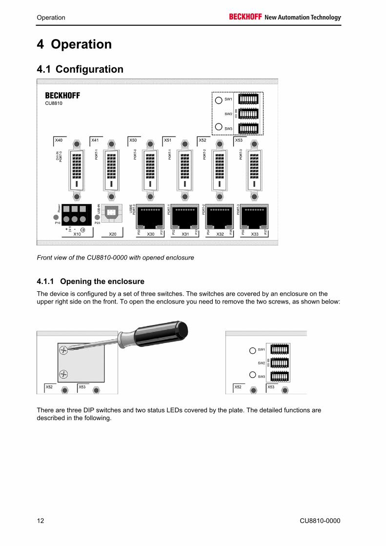
Front view of the CU8810-0000 with opened enclosure
4.1.1 Opening the enclosure The device is configured by a set of three switches. The switches are covered by an enclosure on the upper right side on the front. To open the enclosure you need to remove the two screws, as shown below:
There are three DIP switches and two status LEDs covered by the plate. The detailed functions are described in the following.
12 CU8810-0000

Operation
4.1.2 DIP Switch 1 (SW1) This DIP switch configures the DVI input sources and the DDC signals.
Switch Name Function 1 PWRDVI1 Activate DVI Input Port 0 (X40) 2 PWRDVI2 Activate DVI Input Port 1 (X41) 3 OUT-LEVEL Set output level for DVI Output 4 N.C. Not used 5 A0_0 Address switch A0 for DVI Input Port 0 (X40) 6 A1_0 Address switch A1 for DVI Input Port 0 (X40) 7 A0_1 Address switch A0 for DVI Input Port 1 (X41) 8 A1_1 Address switch A1 for DVI Input Port 1 (X41)
4.1.2.1 PWRDVI1/ PWRDVI2
The first two switches are used to enable/ disable the two DVI Input Ports:
PWRDVI1 Function on DVI Input Port 0 is activated off DVI Input Port 0 is deactivated
PWRDVI2 Function on DVI Input Port 1 is activated off DVI Input Port 1 is deactivated
4.1.2.2 OUT-LEVEL
The next switch 3 is used to set the back termination for the output level. The use of back terminations is highly recommended for best signal integrity.
Factory Settings
Note
This switch is set to off by factory and should only be changed after consultation with the Beckhoff Support.
CU8810-0000 13

Operation
OUT-LEVEL Function on No back termination is used off Back termination is used
4.1.2.3 Switch 5 und 6
Switch 5 and 6 are paired to select the source for the DDC signal for DVI Input Port 0. The DCC signal from the selected port is send to the device connected to DVI Input Port 0.
The following table shows the possible selections.
5 6 Function off off The DDC-channel from DVI Input Port 0 (X40) is connected to DDC-channel to
DVI Output Port 0 (X50) on off The DDC-channel from DVI Input Port 0 (X40) is connected to DDC-channel to
DVI Output Port 1 (X51) off on The DDC-channel from DVI Input Port 0 (X40) is connected to DDC-channel to
DVI Output Port 2 (X52) on on The DDC-channel from DVI Input Port 0 (X40) is connected to DDC-channel to
DVI Output Port 3 (X53)
4.1.2.4 Switch 7 und 8
Switch 7 and 8 are paired to select the source for the DDC signal for DVI Input Port 1. The DCC signal from the selected port is send to the device connected to DVI Input Port 1.
The following table shows the possible selections.
7 8 Function off off The DDC-channel from DVI Input Port 1 (X41) is connected to DDC-channel to
DVI Output Port 0 (X50) on off The DDC-channel from DVI Input Port 1 (X41) is connected to DDC-channel to
DVI Output Port 1 (X51) off on The DDC-channel from DVI Input Port 1 (X41) is connected to DDC-channel to
DVI Output Port 2 (X52) on on The DDC-channel from DVI Input Port 1 (X41) is connected to DDC-channel to
DVI Output Port 3 (X53)
14 CU8810-0000
Operation
Danger of Collision
Note
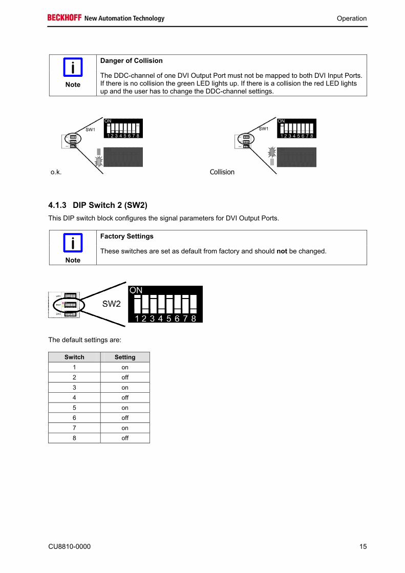
The DDC-channel of one DVI Output Port must not be mapped to both DVI Input Ports. If there is no collision the green LED lights up. If there is a collision the red LED lights up and the user has to change the DDC-channel settings.
o.k. Collision
4.1.3 DIP Switch 2 (SW2) This DIP switch block configures the signal parameters for DVI Output Ports.
Factory Settings
Note
These switches are set as default from factory and should not be changed.
The default settings are:
Switch Setting 1 on 2 off 3 on 4 off 5 on 6 off 7 on 8 off
CU8810-0000 15
Operation
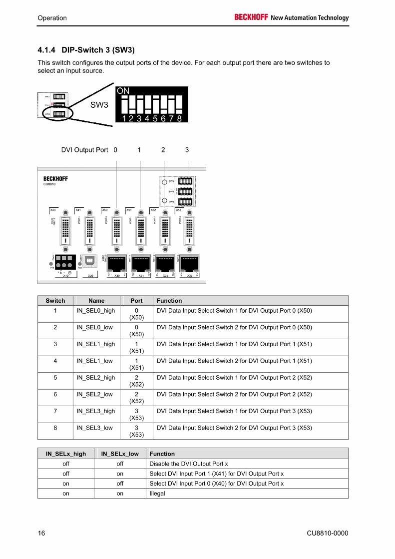
4.1.4 DIP-Switch 3 (SW3) This switch configures the output ports of the device. For each output port there are two switches to select an input source.
Swit1
2
3
4
5
6
7
8
IN_S
16
DVI Output Port 0 1 2 3
ch Name Port Function IN_SEL0_high 0
(X50) DVI Data Input Select Switch 1 for DVI Output Port 0 (X50)
IN_SEL0_low 0 (X50)
DVI Data Input Select Switch 2 for DVI Output Port 0 (X50)
IN_SEL1_high 1 (X51)
DVI Data Input Select Switch 1 for DVI Output Port 1 (X51)
IN_SEL1_low 1 (X51)
DVI Data Input Select Switch 2 for DVI Output Port 1 (X51)
IN_SEL2_high 2 (X52)
DVI Data Input Select Switch 1 for DVI Output Port 2 (X52)
IN_SEL2_low 2 (X52)
DVI Data Input Select Switch 2 for DVI Output Port 2 (X52)
IN_SEL3_high 3 (X53)
DVI Data Input Select Switch 1 for DVI Output Port 3 (X53)
IN_SEL3_low 3 (X53)
DVI Data Input Select Switch 2 for DVI Output Port 3 (X53)
ELx_high IN_SELx_low Function off off Disable the DVI Output Port x off on Select DVI Input Port 1 (X41) for DVI Output Port x on off Select DVI Input Port 0 (X40) for DVI Output Port x on on Illegal
CU8810-0000
Operation
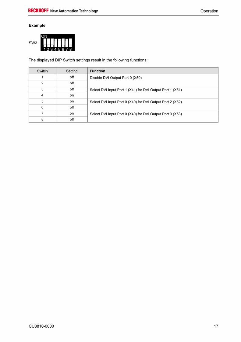
Example
The displayed DIP Switch settings result in the following functions:
Switch Setting Function 1 off 2 off
Disable DVI Output Port 0 (X50)
3 off 4 on
Select DVI Input Port 1 (X41) for DVI Output Port 1 (X51)
5 on 6 off
Select DVI Input Port 0 (X40) for DVI Output Port 2 (X52)
7 on 8 off
Select DVI Input Port 0 (X40) for DVI Output Port 3 (X53)
CU8810-0000 17

Operation
4.2 Architecture Description
4.2.1 Version 1 A PC with DVI output transfers an identical display image to up to four Control Panels. Command signals can be transferred to the PC via USB from each Control Panel.
4.2.2 Version 2 If two PCs with one DVI output each are used, two different images can be transferred to the Control Panels. The two images may have different screen resolutions.
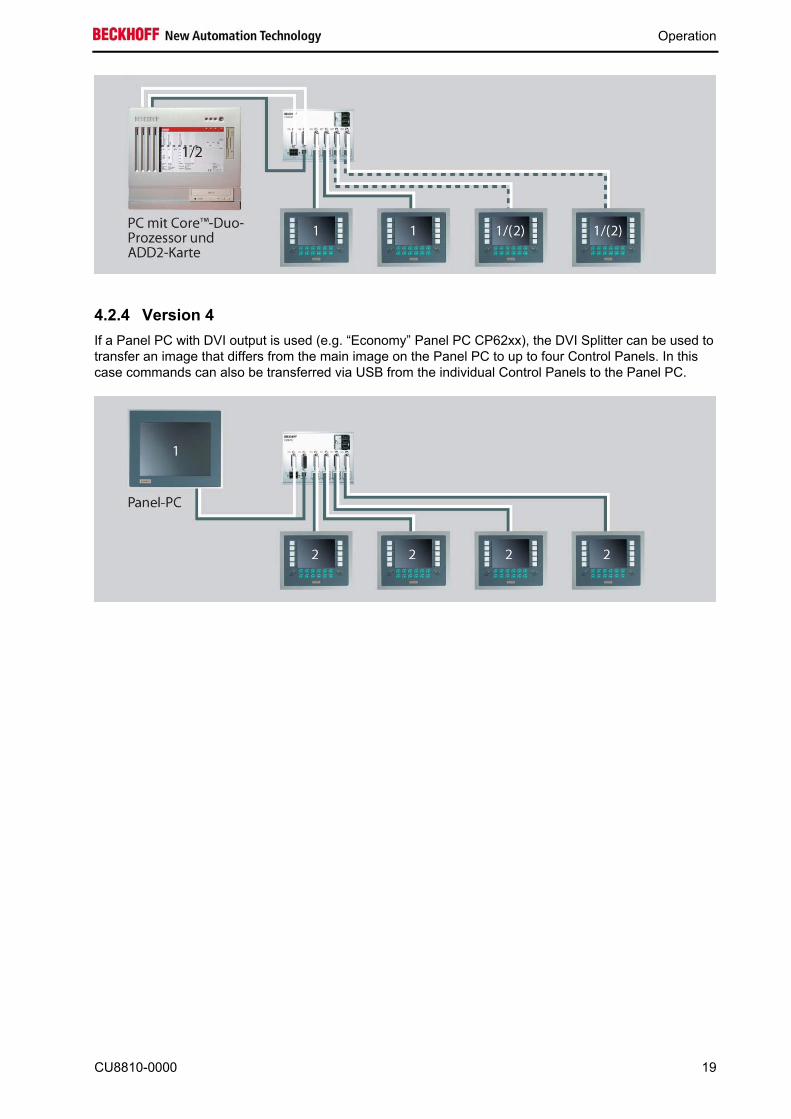
4.2.3 Version 3 The two-PC principle also works using a PC with Core™ Duo technology. If two DVI outputs are used, two different images can be transferred to the Control Panels. The two images may have different screen resolutions. The two-channel C9900-A185 ADD2 card offers a simple option for installing an additional DVI output. The card has two external DVI ports and enables direct connection of two DVI/USB Control Panels to C5102, C6140, C6150, C6240 or C6250 PCs. Via the CU8810, these two DVI outputs can be branched further to up to four Control Panels.
18 CU8810-0000
Operation
4.2.4 Version 4 If a Panel PC with DVI output is used (e.g. “Economy” Panel PC CP62xx), the DVI Splitter can be used to transfer an image that differs from the main image on the Panel PC to up to four Control Panels. In this case commands can also be transferred via USB from the individual Control Panels to the Panel PC.
CU8810-0000 19
Operation
4.3 Maintenance
4.3.1 Cleaning
Disconnect power supply
DANGER
Switch off the device and all connected devices, and disconnect the device from the power supply.
The device can be cleaned with a soft, damp cloth. Do not use any aggressive cleaning materials, thinners, scouring material or hard objects that could cause scratches.
4.3.2 Maintenance The DVI Splitter CU8810-0000 is maintenance-free.
4.4 Shutting down
4.4.1 Disposal
Observe national electronics scrap regulations
Note
Observe the national electronics scrap regulations when disposing of the device.
In order to dispose of the device, it must be removed and fully dismantled:
• Housing components (polycarbonate, polyamide (PA6.6)) are suitable for plastic recycling • Metal parts can be sent for metal recycling • Electronic parts such as disk drives and circuit boards must be disposed of in accordance with
national electronics scrap regulations.
20 CU8810-0000

Dimensions
5 Dimensions The product is characterized by small overall installed size. With a height of approx. 100 mm, the module dimensions exactly match those of the Beckhoff Bus Terminals. Together with the lowered connector surfaces, this means that it can be used in a standard terminal box with a height of 120 mm.
CU8810-0000 21
Technical Data
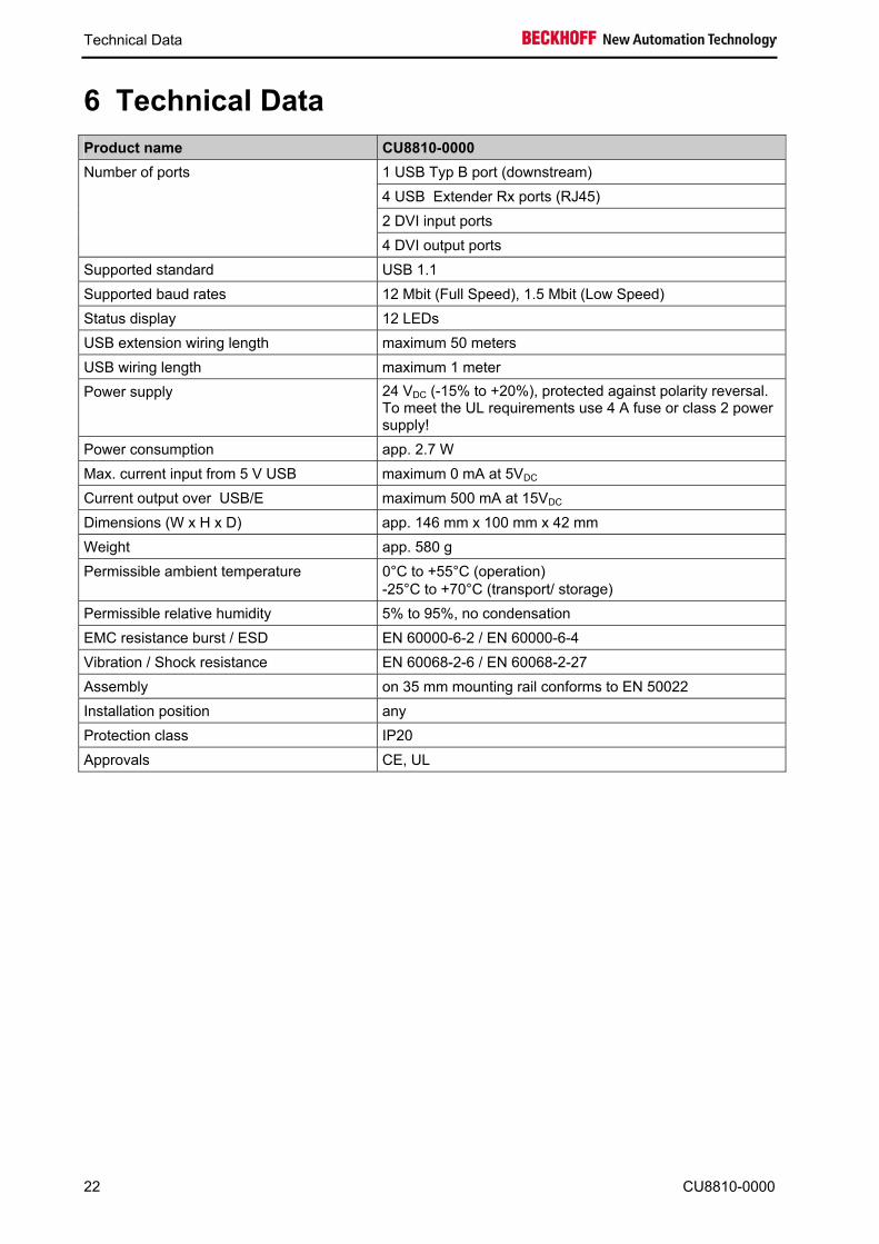
6 Technical Data Product name CU8810-0000
1 USB Typ B port (downstream) 4 USB Extender Rx ports (RJ45) 2 DVI input ports
Number of ports
4 DVI output ports Supported standard USB 1.1 Supported baud rates 12 Mbit (Full Speed), 1.5 Mbit (Low Speed) Status display 12 LEDs USB extension wiring length maximum 50 meters USB wiring length maximum 1 meter Power supply 24 VDC (-15% to +20%), protected against polarity reversal.
To meet the UL requirements use 4 A fuse or class 2 power supply!
Power consumption app. 2.7 W Max. current input from 5 V USB maximum 0 mA at 5VDC Current output over USB/E maximum 500 mA at 15VDC Dimensions (W x H x D) app. 146 mm x 100 mm x 42 mm Weight app. 580 g Permissible ambient temperature 0°C to +55°C (operation)
-25°C to +70°C (transport/ storage) Permissible relative humidity 5% to 95%, no condensation EMC resistance burst / ESD EN 60000-6-2 / EN 60000-6-4 Vibration / Shock resistance EN 60068-2-6 / EN 60068-2-27 Assembly on 35 mm mounting rail conforms to EN 50022 Installation position any Protection class IP20 Approvals CE, UL
22 CU8810-0000

Appendix
7 Appendix
7.1 Beckhoff Support and Service Beckhoff and their partners around the world offer comprehensive support and service, making available fast and competent assistance with all questions related to Beckhoff products and system solutions.
7.1.1 Beckhoff branches and partner companies Please contact your Beckhoff branch office or partner company for local support and service on Beckhoff products! The contact addresses for your country can be found in the list of Beckhoff branches and partner companies: www.beckhoff.com. You will also find further documentation for Beckhoff components there.
7.1.2 Beckhoff company headquarters Beckhoff Automation GmbH & Co. KG Huelshorstweg 20 33415 Verl Germany
Phone: + 49 (0) 5246/963-0 Fax: + 49 (0) 5246/963-198 E-mail: [email protected] Web: http://www.beckhoff.de/
Beckhoff Support Support offers you comprehensive technical assistance, helping you not only with the application of individual Beckhoff products, but also with other, wide-ranging services:
• world-wide support • design, programming and commissioning of complex automation systems • and extensive training program for Beckhoff system components
Hotline: + 49 (0) 5246/963-157 Fax: + 49 (0) 5246/963-9157 E-mail: [email protected]
Beckhoff Service The Beckhoff Service Center supports you in all matters of after-sales service:
• on-site service • repair service • spare parts service • hotline service
Hotline: + 49 (0) 5246/963-460 Fax: + 49 (0) 5246/963-479 E-mail: [email protected]
If servicing is required, please quote the project number of your product.
CU8810-0000 23

Appendix
24 CU8810-0000
7.2 Approvals for USA and Canada
7.3 FCC Approval for USA FCC: Federal Communications Commission Radio Frequency Interference Statement This equipment has been tested and found to comply with the limits for a Class A digital device, pursuant to Part 15 of the FCC Rules. These limits are designed to provide reasonable protection against harmful interference when the equipment is operated in a commercial environment. This equipment generates, uses, and can radiate radio frequency energy and, if not installed and used in accordance with the instruction manual, may cause harmful interference to radio communications. Operation of this equipment in a residential area is likely to cause harmful interference in which case the user will be required to correct the interference at his own expense.
Technical modifications
Note
Technical modifications to the device may cause the loss of the FCC approval.
7.4 FCC Approval for Canada FCC: Canadian Notice This equipment does not exceed the Class A limits for radiated emissions as described in the Radio Interference Regulations of the Canadian Department of Communications.


