32
1 Installation and Operating Instructions Vertical and Horizontal Forced Air/Hydronic GV/GH 36 Thru 67 Series GeoSource DualTEK

1
Installation and
Operating Instructions
Vertical and Horizontal Forced Air/Hydronic
GV/GH 36 Thru 67 Series
Geo
Sour
ce D
ualT
EK

Licensed under U.S. Patent Number 4,856,578
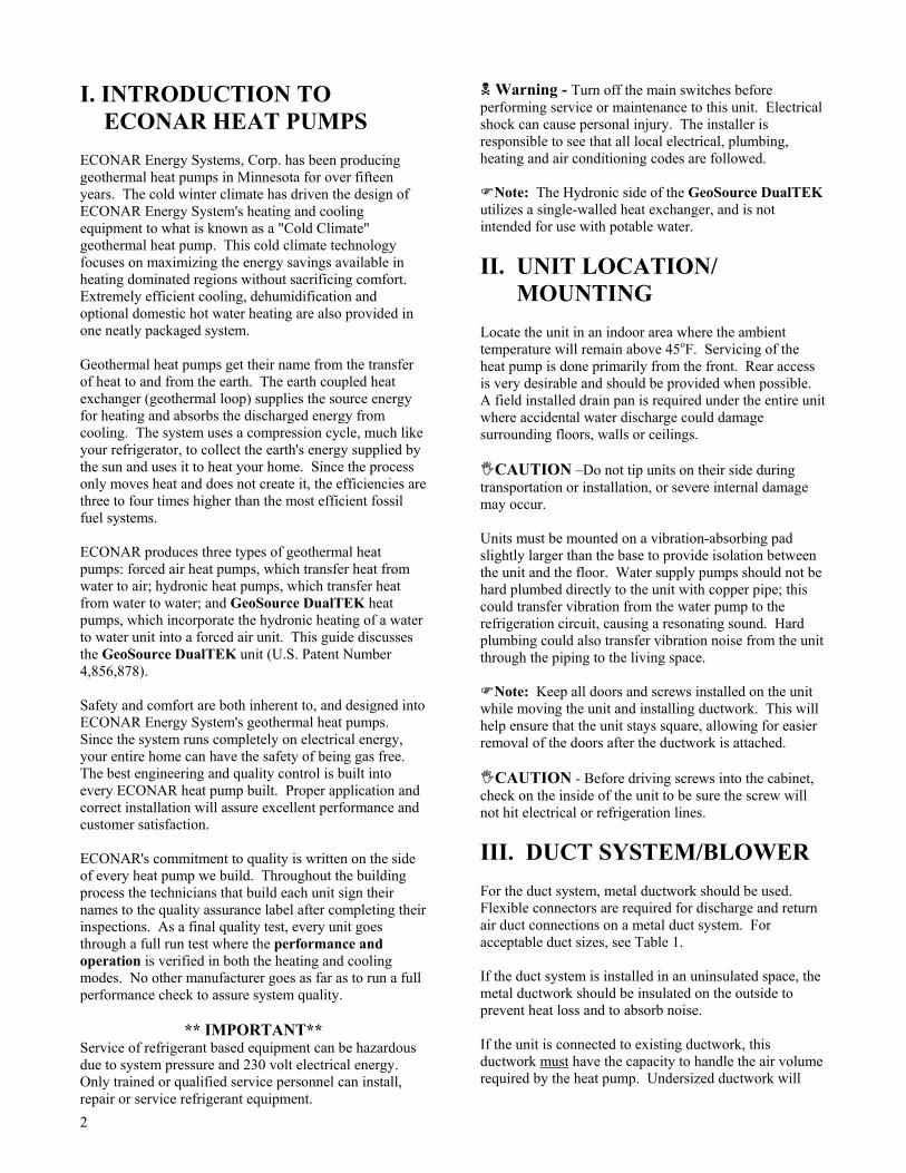
Contactor
GeoSource DualTEK Horizontal Unit
Air Coil
Blower
Air Pad
Controller
Reversing Valve
Transformer
Scroll Compressor
Blower
Contactor
Expansion Valve
Scroll Compressor
Air Pad
Air Coil
Transformer
Controller
Reversing Valve
Desuperheater (Optional)
GeoSource DualTEK Vertical Unit
Air Filter

1
TABLE OF CONTENTS Section Title Page
I. Introduction to ECONAR Heat Pumps . . . . . . . . . . . . . . . . . . . . . . . . . . 2
II. Unit Location/Mounting . . . . . . . . . . . . . . . . . . . . . . . . . . . . . . . . . . . . . . 2
III. Duct System/Blower . . . . . . . . . . . . . . . . . . . . . . . . . . . . . . . . . . . . . . . . . . 2
IV. Hydronic Side Heat Exchangers . . . . . . . . . . . . . . . . . . . . . . . . . . . . . . . . 4 A. Radiant Floor Heating B. Baseboard Heating C. Other Applications D. Temperature Limitations
V. Applications of Hydronic Side Heat Exchangers . . . . . . . . . . . . . . . . . . . 5 A. Storage Tanks B. Hydronic Side Circulators C. Circulation Fluid D. Expansion Tanks E. Application Diagrams
VI. Earth Loop Water Piping . . . . . . . . . . . . . . . . . . . . . . . . . . . . . . . . . . . . . 9 A. Closed Loop Applications B. Open Loop Applications 1) Open Loop Freeze Protection Switch
2) Water Coil Maintenance a. Freeze Cleaning b. Chlorine Cleaning c. Miratic Acid Cleaning
VII. Condensate Drain . . . . . . . . . . . . . . . . . . . . . . . . . . . . . . . . . . . . . . . . . . . 12
VIII. Unit Sizing . . . . . . . . . . . . . . . . . . . . . . . . . . . . . . . . . . . . . . . . . . . . . . . . . 13 A. Earth Loop Configuration and Design Water Temperatures B. Hydronic Side Heat Exchanger Operating Temperatures C. Building Heat Loss/Heat Gain D. Temperature Limitations
IX. Electrical Service . . . . . . . . . . . . . . . . . . . . . . . . . . . . . . . . . . . . . . . . . . . . 14
X. 24 Volt Control Circuit . . . . . . . . . . . . . . . . . . . . . . . . . . . . . . . . . . . . . . . 14 A. Transformer B. Thermostat/Aquastat C. Controller
1) Blower Operation 2) Earth Loop Pump Initiation 3) Compressor Operation 4) 4-Way Valve Control 5) Compressor Lockouts 6) Compressor Anti-Short-Cycle 7) System Diagnostics 8) Forced Air/Hydronic Priority 9) Overflow Detection
XI. Startup . . . . . . . . . . . . . . . . . . . . . . . . . . . . . . . . . . . . . . . . . . . . . . . . . . . . 17
XII. Service . . . . . . . . . . . . . . . . . . . . . . . . . . . . . . . . . . . . . . . . . . . . . . . . . . . . . 18 A. Filter B. Lockout Lights C. Preseason Inspection
XIII. Thermostat Operation . . . . . . . . . . . . . . . . . . . . . . . . . . . . . . . . . . . . . . 18
XIV. Troubleshooting Guide For Unit Operation . . . . . . . . . . . . . . . . . . . . . . 19
XV. Troubleshooting Guide For Lockout Conditions . . . . . . . . . . . . . . . . . . 22
XVI. Additional Figures and Tables . . . . . . . . . . . . . . . . . . . . . . . . . . . . . . . . . 22
XVII. Desuperheater (Optional) . . . . . . . . . . . . . . . . . . . . . . . . . . . . . . . . . . . . . 26
2
I. INTRODUCTION TO ECONAR HEAT PUMPS ECONAR Energy Systems, Corp. has been producing geothermal heat pumps in Minnesota for over fifteen years. The cold winter climate has driven the design of ECONAR Energy System's heating and cooling equipment to what is known as a "Cold Climate" geothermal heat pump. This cold climate technology focuses on maximizing the energy savings available in heating dominated regions without sacrificing comfort. Extremely efficient cooling, dehumidification and optional domestic hot water heating are also provided in one neatly packaged system. Geothermal heat pumps get their name from the transfer of heat to and from the earth. The earth coupled heat exchanger (geothermal loop) supplies the source energy for heating and absorbs the discharged energy from cooling. The system uses a compression cycle, much like your refrigerator, to collect the earth's energy supplied by the sun and uses it to heat your home. Since the process only moves heat and does not create it, the efficiencies are three to four times higher than the most efficient fossil fuel systems. ECONAR produces three types of geothermal heat pumps: forced air heat pumps, which transfer heat from water to air; hydronic heat pumps, which transfer heat from water to water; and GeoSource DualTEK heat pumps, which incorporate the hydronic heating of a water to water unit into a forced air unit. This guide discusses the GeoSource DualTEK unit (U.S. Patent Number 4,856,878). Safety and comfort are both inherent to, and designed into ECONAR Energy System's geothermal heat pumps. Since the system runs completely on electrical energy, your entire home can have the safety of being gas free. The best engineering and quality control is built into every ECONAR heat pump built. Proper application and correct installation will assure excellent performance and customer satisfaction. ECONAR's commitment to quality is written on the side of every heat pump we build. Throughout the building process the technicians that build each unit sign their names to the quality assurance label after completing their inspections. As a final quality test, every unit goes through a full run test where the performance and operation is verified in both the heating and cooling modes. No other manufacturer goes as far as to run a full performance check to assure system quality.
** IMPORTANT** Service of refrigerant based equipment can be hazardous due to system pressure and 230 volt electrical energy. Only trained or qualified service personnel can install, repair or service refrigerant equipment.
! Warning - Turn off the main switches before performing service or maintenance to this unit. Electrical shock can cause personal injury. The installer is responsible to see that all local electrical, plumbing, heating and air conditioning codes are followed. "Note: The Hydronic side of the GeoSource DualTEK utilizes a single-walled heat exchanger, and is not intended for use with potable water.
II. UNIT LOCATION/ MOUNTING Locate the unit in an indoor area where the ambient temperature will remain above 45oF. Servicing of the heat pump is done primarily from the front. Rear access is very desirable and should be provided when possible. A field installed drain pan is required under the entire unit where accidental water discharge could damage surrounding floors, walls or ceilings. #CAUTION �Do not tip units on their side during transportation or installation, or severe internal damage may occur. Units must be mounted on a vibration-absorbing pad slightly larger than the base to provide isolation between the unit and the floor. Water supply pumps should not be hard plumbed directly to the unit with copper pipe; this could transfer vibration from the water pump to the refrigeration circuit, causing a resonating sound. Hard plumbing could also transfer vibration noise from the unit through the piping to the living space. "Note: Keep all doors and screws installed on the unit while moving the unit and installing ductwork. This will help ensure that the unit stays square, allowing for easier removal of the doors after the ductwork is attached. #CAUTION - Before driving screws into the cabinet, check on the inside of the unit to be sure the screw will not hit electrical or refrigeration lines.
III. DUCT SYSTEM/BLOWER For the duct system, metal ductwork should be used. Flexible connectors are required for discharge and return air duct connections on a metal duct system. For acceptable duct sizes, see Table 1. If the duct system is installed in an uninsulated space, the metal ductwork should be insulated on the outside to prevent heat loss and to absorb noise. If the unit is connected to existing ductwork, this ductwork must have the capacity to handle the air volume required by the heat pump. Undersized ductwork will

3
cause noisy operation and poor operating efficiencies due to lack of airflow. The standard GeoSource DualTEK (-Gxxxx-x-Dx0x) heat pumps use a 230 Volt three-speed blower. For maximum airflow, the blower should be on high speed. Moving the wire on the fan terminal strip can change the fan speed. For blower data and factory settings, see Table 2. An optional variable speed ECM blower motor is available on the GeoSource DualTEK (Gxxxx-x-DxVx) series heat pumps. These motors convert 230 Volt AC power to DC power internally. The DC power can then be modulated to turn the motor at a variety of speeds. The blower�s speed is modulated based on what the thermostat is calling for. If the thermostat is calling for only the FAN to operate, the blower will put out a low amount of airflow in cubic feet per minute (CFM). This low CFM output will gently circulate air throughout the house, eliminating hot or cold spots, and actually reduce the need for mechanical heating or cooling at certain times of the year. The blower can supply this minimal CFM output with a very low electrical usage. When the thermostat calls for first stage forced air heating or cooling, the fan speed slowly begins to increase speed. Because of the slow ramping of the blower speed, full speed on first stage may not be achieved until nearly four minutes have elapsed from the initial call. This enables the blower to have very quiet starts, and helps minimize cold blasts of air in the winter. It also provides increased dehumidification in the summer and warmer, more comfortable discharge air in the winter. When the thermostat calls for second stage heating, it will bring the
fan speed up to high speed. The fan speeds of the GeoSource DualTEK heat pumps are factory set to provide the highest efficiency at each stage of operation, but may be adjusted slightly in the field to increase comfort. These settings are shown in Table 3. The controller provides a total of 12 fan speed set points. There are four different CFM outputs in each of the three fan speed ranges (Low, Medium, and High). These CFM outputs are factory set, and should not be changed in the field. There is an Adjust setting, which allows the blower to be operated at +/- 10% of the factory setting. For example, if the Adjust tap is set to the �-�, all the speeds will operate at 90% of the factory setting. If the Adjust tap is set to the �+�, all the speeds will operate at 110% of the factory setting. The Adjust tap is the only tap on the Blower Speed Controller that should ever be moved from the factory setting. The blower motor also provides internal circuitry that will try to maintain the setpoint CFM when changes occur in the external static pressure, such as the filter getting dirty over time. The motor does this by increasing its torque output to compensate for external resistance changes. The blower is also programmed to provide soft starting to reduce air noise, delays after compressor shutdown to distribute all the heat output from the compressor to the heated space, and ramped speed changes. All these features are designed for quiet, comfortable, efficient operation. "Note: The blower will not operate properly if ductwork is not attached. The ductwork supplies static pressure to give the blower motor a load to work against. Blower motors may overheat if run for an extended period of time without ductwork attached.
Table 1 � Duct Sizing Chart
Acceptable Branch Duct Sizes Acceptable Main or Trunk Duct Sizes CFM Round Rectangular Round Rectangular
50 4" 4x4 75 5" 4x5, 4x6
100 6" 4x8, 4x6 150 7" 4x10, 5x8, 6x6 200 8" 5x10, 6x8, 4x14, 7x7 250 9" 6x10, 8x8, 4x16 300 10" 6x14, 8x10, 7x12 350 10" 6x20, 6x16, 9x10 400 12" 6x18, 10x10, 9x12 10" 4x20, 7x10, 6x12, 8x9 450 12" 6x20, 8x14, 9x12, 10x11 10" 5x20, 6x16, 9x10, 8x12 500 10" 10x10, 6x18, 8x12, 7x14 600 12" 6x20, 7x18, 8x16, 10x12 800 12" 8x18, 9x15, 10x14, 12x12 1000 14" 10x18, 12x14, 8x24 1200 16" 10x20, 12x18, 14x15 1400 16" 10x25, 12x20, 14x18, 15x16 1600 18" 10x30, 15x18, 14x20 1800 20" 10x35, 15x20, 16x19, 12x30, 14x25 2000 20" 10x40, 12x30, 15x25, 18x20 2200 22" 10x45, 15x28, 18x22, 20x20
Tables calculated for 0.05 to 0.10 inches of water friction per 100� of duct. At these duct design conditions, along with the pressure drop through the filter, the total design external static pressure is 0.20 inches of water. Normal airflow at 0.20 inches of water should then be used for these calculations.
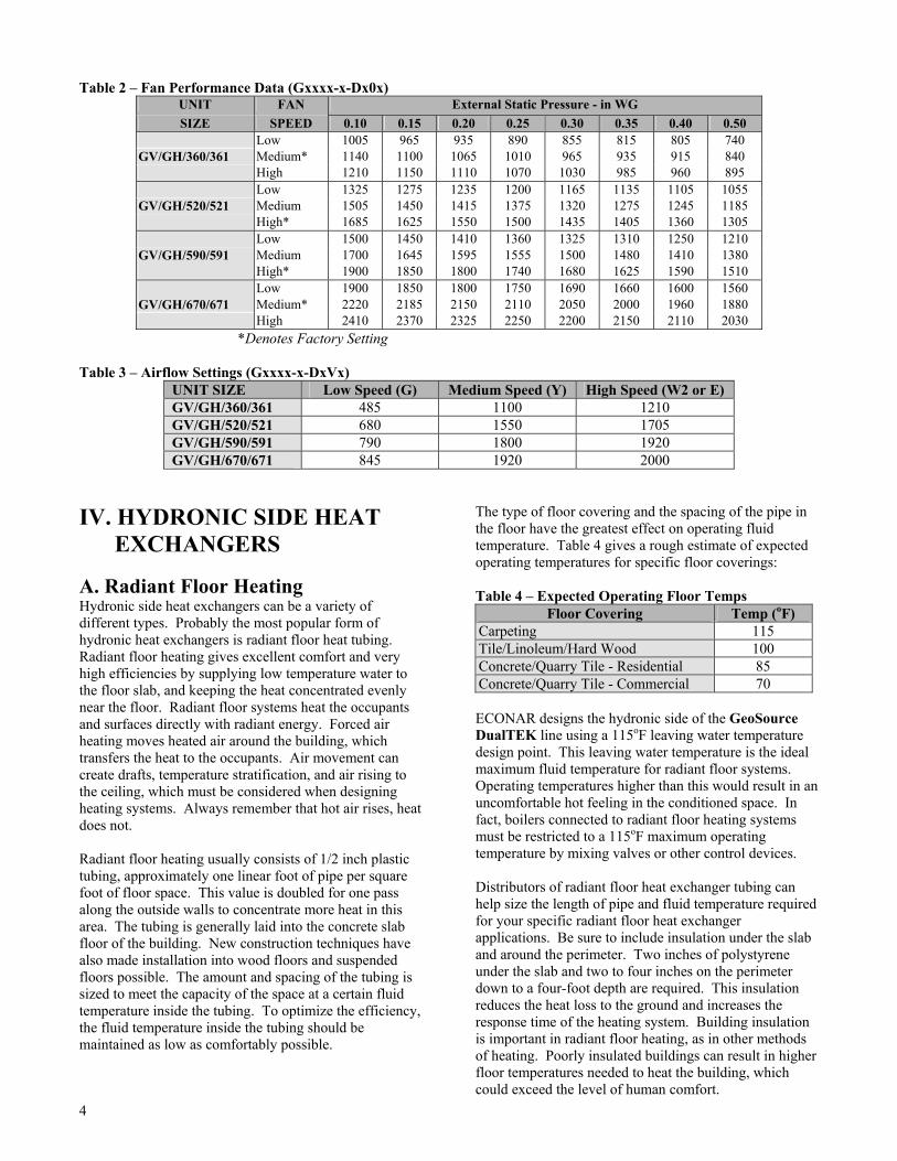
4
Table 2 � Fan Performance Data (Gxxxx-x-Dx0x) UNIT FAN External Static Pressure - in WG SIZE SPEED 0.10 0.15 0.20 0.25 0.30 0.35 0.40 0.50
Low 1005 965 935 890 855 815 805 740 GV/GH/360/361 Medium* 1140 1100 1065 1010 965 935 915 840
High 1210 1150 1110 1070 1030 985 960 895 Low 1325 1275 1235 1200 1165 1135 1105 1055
GV/GH/520/521 Medium 1505 1450 1415 1375 1320 1275 1245 1185 High* 1685 1625 1550 1500 1435 1405 1360 1305 Low 1500 1450 1410 1360 1325 1310 1250 1210
GV/GH/590/591 Medium 1700 1645 1595 1555 1500 1480 1410 1380 High* 1900 1850 1800 1740 1680 1625 1590 1510 Low 1900 1850 1800 1750 1690 1660 1600 1560
GV/GH/670/671 Medium* 2220 2185 2150 2110 2050 2000 1960 1880 High 2410 2370 2325 2250 2200 2150 2110 2030
*Denotes Factory Setting Table 3 � Airflow Settings (Gxxxx-x-DxVx)
UNIT SIZE Low Speed (G) Medium Speed (Y) High Speed (W2 or E) GV/GH/360/361 485 1100 1210 GV/GH/520/521 680 1550 1705 GV/GH/590/591 790 1800 1920 GV/GH/670/671 845 1920 2000
IV. HYDRONIC SIDE HEAT EXCHANGERS A. Radiant Floor Heating Hydronic side heat exchangers can be a variety of different types. Probably the most popular form of hydronic heat exchangers is radiant floor heat tubing. Radiant floor heating gives excellent comfort and very high efficiencies by supplying low temperature water to the floor slab, and keeping the heat concentrated evenly near the floor. Radiant floor systems heat the occupants and surfaces directly with radiant energy. Forced air heating moves heated air around the building, which transfers the heat to the occupants. Air movement can create drafts, temperature stratification, and air rising to the ceiling, which must be considered when designing heating systems. Always remember that hot air rises, heat does not. Radiant floor heating usually consists of 1/2 inch plastic tubing, approximately one linear foot of pipe per square foot of floor space. This value is doubled for one pass along the outside walls to concentrate more heat in this area. The tubing is generally laid into the concrete slab floor of the building. New construction techniques have also made installation into wood floors and suspended floors possible. The amount and spacing of the tubing is sized to meet the capacity of the space at a certain fluid temperature inside the tubing. To optimize the efficiency, the fluid temperature inside the tubing should be maintained as low as comfortably possible.
The type of floor covering and the spacing of the pipe in the floor have the greatest effect on operating fluid temperature. Table 4 gives a rough estimate of expected operating temperatures for specific floor coverings: Table 4 � Expected Operating Floor Temps
Floor Covering Temp (oF) Carpeting 115 Tile/Linoleum/Hard Wood 100 Concrete/Quarry Tile - Residential 85 Concrete/Quarry Tile - Commercial 70 ECONAR designs the hydronic side of the GeoSource DualTEK line using a 115oF leaving water temperature design point. This leaving water temperature is the ideal maximum fluid temperature for radiant floor systems. Operating temperatures higher than this would result in an uncomfortable hot feeling in the conditioned space. In fact, boilers connected to radiant floor heating systems must be restricted to a 115oF maximum operating temperature by mixing valves or other control devices. Distributors of radiant floor heat exchanger tubing can help size the length of pipe and fluid temperature required for your specific radiant floor heat exchanger applications. Be sure to include insulation under the slab and around the perimeter. Two inches of polystyrene under the slab and two to four inches on the perimeter down to a four-foot depth are required. This insulation reduces the heat loss to the ground and increases the response time of the heating system. Building insulation is important in radiant floor heating, as in other methods of heating. Poorly insulated buildings can result in higher floor temperatures needed to heat the building, which could exceed the level of human comfort.
5
Night setback thermostats are not recommended on radiant floor systems due to the response time of the slab. B. Baseboard Heating Another application of hydronic heating is finned tube baseboard heating. This is the same tubing used with boilers with one major difference. The discharge temperature of a boiler is much higher than geothermal heat pumps. The heat pump system should be sized at 115oF hydronic leaving water temperature to maintain efficiency. At a 125oF leaving water temperature, the heat pump is at a maximum operating temperature and may start to trip off on high head pressures. Standard 3/4" finned tube baseboard conductors have an average output of 230 Btuh/ft at 120oF hydronic leaving water temperature. In most cases there is not enough perimeter area in the conditioned space to allow for the required length of tubing to handle the entire heating load. There have been successful installations using baseboard heating as supplemental heating using the forced air side of the GeoSource DualTEK unit to satisfy the heating load. Cast iron radiators have also been used successfully. If these radiators are rated for an output of 70 Btuh/square inch at a 130oF hydronic leaving water temperature, they work well with geothermal systems. Although the radiator may be rated at 130oF, the system should still operate at the standard 115oF leaving water temperature of the hydronic side of the heat pump. C. Other Applications Additional open loop hydronic applications such as outdoor swimming pools, hot tubs, whirlpools, tank heating, etc. are easily sized based on heat exchanger operating temperature and flow. The worksheet in Appendix 1 was taken from the ASHRAE 95 Applications Manual and can be used for outdoor swimming pool sizing. In many instances, sizing a heat pump to these applications comes down to recovery time. The larger the heat pump (within reason to avoid short cycling) the faster the system recovery time will be. "Note: Installing a plate heat exchanger (see Figure 3 for an example) between the heat pump and an open system is required when corrosive fluid is used in the open loop, especially on swimming pools where pH imbalance can damage the heat pump. "Note: Expect the maximum operating temperature of an indirect coupled application to be 10oF below the maximum operating temperature of the heat pump. Other forms of closed loop systems such as indoor swimming pools, pretreated fresh air systems, snow melt systems, and valance heating systems are also very common with GeoSource DualTEK heat pumps. The sizing of the heat pump to these systems is more precise and information from the system manufacturer is required.
V. APPLICATIONS OF HYDRONIC SIDE HEAT EXCHANGERS This section deals with some common practices used when coupling the hydronic side of an ECONAR GeoSource DualTEK heat pump to the space conditioning heat exchanger. There are so many possible applications for these systems that they cannot all be covered in this text. Hopefully these ideas can help in many of your system designs. "Note: Actual systems must be constructed to all appropriate codes and according to accepted plumbing practices. A. Storage Tanks Coupling the hydronic side of the heat pump to the space conditioning heat exchanger through a water storage tank is very common. In fact, the only instance where these storage tanks are not recommended is when the heat pump is coupled to a large heat exchanger capable of absorbing the entire heating capacity of the heat pump (see Figure 2). In applications that use multiple smaller zones, storage tanks absorb the relatively large amount of energy supplied by the heat pump, in order to provide longer run times and less compressor cycling for the heat pump. Storage tanks also serve to dispense energy in small amounts so that the conditioned zones have time to absorb heat without requiring high discharge water temperatures. Insulated hot water heaters are commonly used for storage tanks. "Note: While all hot water tanks are insulated on the top and sides, many do not have insulation on the bottom. An insulated pad beneath uninsulated tanks will reduce energy loss to the floor. When properly sized, a storage tank eliminates many problems with multiple zone hydronic systems. These problems include excessive leaving water temperature if a single zone cannot dissipate heat quickly enough and hydronic flow reduction through the heat pump when only one zone is calling. This may occur because the hydronic side circulating pump is normally sized to provide the heat pump�s required flow with all zones calling. When sizing storage tanks to the heat pump, a good rule of thumb is ten gallons of storage tank per ton of hydronic capacity. The tank temperature can be controlled with a simple aquastat or a setpoint controller. The setpoint controller senses tank water temperature and outside air temperature to increase the tank temperature as the outside air temperature goes down. This control scheme provides the highest heating efficiencies by requiring the lowest possible water temperature to heat the space. Setting the optimal design temperatures in the controller is difficult,

6
and the simple aquastat does have its advantages. To help in setpoint control, the following equation can be used. Reset Ratio = Design Water Temp � Indoor Design Temp Indoor Design Temp � Outdoor Design Temp Always check local codes to be sure hot water heaters can be used as storage tanks. Using the electric elements in the tank as a secondary heat source to the heat pump is appealing in some applications, but special UL listing is required by many local codes. Specially listed hot water heaters are available. B. Hydronic Side Circulators Hydronic circulator pumps transfer the energy supplied by the hydronic side of ECONAR's GeoSource DualTEK heat pumps to the space conditioning heat exchanger. When selecting a circulator, be sure to select a quiet operating pump with the ability to supply the required flow rate at the system pressure drop. The circulator supplying the heat pump should be placed in the water supply line into the unit to provide the best pump performance. Individual zone circulators should also be placed in the supply lines of the heat exchangers they serve (Figure 3). These pumps are often used as the on/off control mechanism for the zone they supply. Zone valves are also commonly used for this purpose using a common pump (shown in Figure 1). "Note: Select a common pump at the total flow of all the zones and the highest pressure drop of any one parallel zone. Small Grundfos pumps (230 VAC) can be used as circulator pumps. These pumps are impedance protected and do not require additional fusing if powered directly from the heat pump, since the heat pump is rated to accept up to a 1/3 horsepower circulator. If impedance protected pumps are not used, inline fuses should be supplied according to code. Pumps must be sized to provide the required flow to a heat exchanger at its corresponding pressure drop. This pressure drop can be calculated from the total pressure drop through the piping, added to the pressure drop of the space conditioning heat exchanger. The hydronic side pressure drop through each particular heat pump is listed in Table 5. This table can be used for sizing the circulating pump between the hydronic side of the heat pump and a storage tank.
Table 5 � Storage Tank Circulators
Hydronic Loop Grundfos Series Flow (gpm) dP (psi) Circulator
36 5 1.7 15-42F (Brute) 52 7 4.8 26-116 59 9 7.0 26-116 67 11 11.7 26-116 x Two
This table represents the minimum pump sizing required to supply the heat pump's required hydronic side flow rate at the pressure drop of the heat pump and 30 feet of 3/4" type K copper tubing or combination of elbows and pipe. A common problem with circulator pumps is trapped air in the system. This air accumulates in the suction port of the circulator causing cavitation in the pump, which leads to premature pump failure and noisy operation. The air can be eliminated by completely purging the system or by placing an air separator in the plumbing lines. The entire system must be purged of air during initial installation and pressurized to a 10-25 psi static pressure to avoid air entering the system. This initial static pressure may fluctuate but should always remain above zero. If a leak in the system allows the static pressure to drop, the leak must be repaired to assure proper system operation. Air continually entering the loop can cause corrosion, bacteria, or pump cavitation. The hydronic side circulator supplying the heat pump should be controlled to run only when the compressor is also running. If the circulator pump is allowed to circulate cold water through the system during off cycles, the refrigerant in the heat pump will migrate to the hydronic side heat exchanger. This can cause heat pump starting problems. C. Circulation Fluid The fluid circulating through the hydronic side of the GeoSource DualTEK heat pump system is the transfer medium for the heating being supplied to the conditioned space. Selection of this fluid is very important. Water is the most readily available fluid but has the drawback of expansion during freezing which can damage the system. Extended power interruption to a structure or the disabling of an outside zone (such as a garage floor) provides an opportunity for freezing of the circulating fluid. Antifreeze must be used whenever the possibility of freezing exists from the environment. A propylene glycol based antifreeze (readily available through HVAC wholesalers) and water solution is recommended. Methanol based antifreeze is not recommended for use on any hydronic system where heat is being added to the system for structural heating purposes. Freeze protection for the hydronic side fluid down to 20oF (20% propylene glycol by volume in water) is recommended for most indoor applications (see Chart 1). Forty percent propylene glycol in water (-5oF freeze protection) is recommended by radiant tubing manufactures for snow melt applications, in order to protect the tubing from expansion in outdoor applications. Using over 40% in hydronic side applications can cause pumping problems due to high viscosity. The water being added to the system should have 100-PPM grain hardness or less. If poor water conditions

7
exist on the site, softened water is recommended, or acceptable water should be brought in. Bacteria or algae growth in the water is a possibility, especially bacteria or algae that thrive at the particular temperatures produced in the heating system. This growth can cause buildup on hydronic side heat exchanger surfaces, reducing the efficiency of the system or causing the heat pump to run at higher head pressures and possibly lock out. Adding a gallon of bleach or boiler system conditioner can reduce the possibility of growth and clean up visual flow meters and other components in the system. Chart 1 -Propylene Glycol/Water Solution Freeze Point
D. Expansion Tanks Expansion tanks must be used in the hydronic side of the GeoSource DualTEK heat pump system to absorb the change in pressure of the closed system due to the change
in temperature when heat is supplied to the system. Diaphragm-type expansion tanks should be used. The diaphragm in these tanks is filled with pressurized air, which expands, or contracts to maintain a constant overall system pressure as the fluid in the system expands with increasing temperature. Use EPDM diaphragm tanks because they are compatible with glycol-based antifreeze fluids (butyl rubber diaphragms will slowly dissolve with glycol-based antifreezes). Tanks from 1 to 10 gallons are generally used with heat pump systems in residential and light commercial applications. Expansion tanks should be installed in the system near the suction of the circulator pump whenever possible. This maintains positive pressure at the circulator pump and reduces the highest working pressure of the system. A pressure gauge near the inlet of the expansion tank gives a good indication of how the system is operating. Pressure relief valves are required on all hydronic applications. A 30 psi relief is adequate if the system is operated at 12 to 15 psi pressure. If a hot water heater is used for a storage tank, the 150 psi pressure relief may be acceptable (check local codes). E. Application Diagrams Figures 1 through 3 show the components of a GeoSource DualTEK heat pump system discussed above used in some common applications. These figures by no means represent all the possible heat pump applications, but they do show some important principals that can be applied to any system.
Figure 1 �GeoSource DualTEK Heat Pump � Multizone Hydronic Heating and Forced Air Heating/Cooling

8
Figure 2 � GeoSource DualTEK Heat Pump � Single Zone Hydronic Heating and Forced Air Heating/Cooling
Note: Expect a 10°F temperature differential between supply storage tank and open hydronic loop when transferring heat with intermediate heat exchanger. Figure 3 � GeoSource DualTEK Heat Pump � Multizone Hydronic Heating, Forced Air Heating/Cooling, and Intermediate Pool Heat Exchanger

9
VI. EARTH LOOP WATER PIPING Since water is the source of energy in the wintertime and the energy sink in the summertime, good water supply is possibly the most important requirement of a geothermal heat pump system installation. There are two common types of water supplies, closed loop systems and open loop systems. A. Closed Loop Applications A closed loop system recirculates the same water/antifreeze solution through a closed system of underground high-density polyethylene pipe. As the solution passes through the pipe, it collects heat (in the heating mode) that is being transferred from the relatively warm surrounding soil through the pipe and into the relatively cold solution. The solution is circulated to the heat pump, which pulls heat out of the solution, and then back through the ground to extract more heat from the earth. The GeoSource DualTEK is designed to operate on either vertical or horizontal closed loop applications. Vertical loops are typically installed with a well drilling rig up to 200 feet deep or more. Horizontal systems are typically installed with excavating or trenching equipment approximately six to eight feet deep, depending on geographic location and length of pipe used. Earth loops must be sized properly for each particular geographic
Figure 4 � Closed Loop Water Plumbing
area, soil type, and individual capacity requirements. Contact your local installer or ECONAR�s Customer Support for loop sizing requirements in your area. Since normal wintertime operating entering water temperatures (EWT) to the heat pump are from 25oF to 32oF, the solution in the earth loop must include antifreeze. GTF and propylene glycol are common antifreeze solutions. GTF is methanol-based antifreeze, which should be mixed 50% with water to achieve freeze protection of 10oF. Propylene glycol antifreeze solution should be mixed 25% with water to obtain a 15oF freeze protection. DO NOT mix more than 25% propylene glycol with water in an attempt to achieve a lower than 15oF freeze protection, since more concentrated mixtures of propylene glycol become too viscous at low temperatures and cannot be pumped through the earth loop. Insufficient amounts of antifreeze may result in a freeze rupture of the unit, and can cause unit shutdown problems during cold weather operation (when the heat pump experiences the longest run time) due to loop temperatures falling below the freeze protection of the loop solution. Flow rate requirements for closed loops are higher than open loop systems because water temperatures supplied to the heat pump are generally lower (see Table 6). Between 2.5 to 3.0 gallons per minute (GPM) per ton are required for proper operation of the heat pump and the earth coupled heat exchanger.

10
Table 6 � Loop Side Flow Rates Model Closed Loop Open Loop
Flow dP Flow dP (gpm) (psi) (gpm) (psi)
G(V,H)36 8 5.5 4 1.3 G(V,H)52 11 5.2 6 1.6 G(V,H)59 13 6.0 9 3.1 G(V,H)67 14 7.0 10 3.8 Pressure/Temperature (P/T) ports should be installed in the entering and leaving water lines of the heat pump on a closed loop system (see Figure 4). A thermometer can be inserted into the P/T ports to check entering and leaving water temperatures. A pressure gauge can also be inserted into these P/T ports to determine the pressure differential between the entering and leaving water. This pressure differential can then be compared to the specification data on each particular heat pump to determine the flow rate of the system. A PumpPAK that is individually sized for each application can supply pumping requirements for the earth loop fluid. The PumpPAK can also be used to purge the loop system. The PumpPAK is wired directly to the contactor and operates whenever the compressor runs (see Electrical Diagrams � Figures 8 and 9). If a PumpPAK is not used, a separate pump can be used which is energized with a pump relay (note: electrical code will require a fused disconnect for pumps other than PumpPAKs). Filling and purging a closed loop system are very important steps to assure proper heat pump operation. Each loop must be purged with enough water flow to assure a two feet per second flow rate in each circuit in the loop. This normally requires a 1½ to 3 HP high head pump to circulate fluid through the loop to remove all the air out of the loop and into a purging tank. Allow the pump to run 10 to 15 minutes after the last air bubbles have been removed. Enough antifreeze must be added to give a 10oF to 15oF freeze protection to the earth loop system. This amount should be calculated and added to the loop after purging is complete. After antifreeze has been installed it should be measured with a hydrometer, refractometer or any other device to determine the actual freezing point of the solution. Remember that a low antifreeze level will lock the heat pump out on low pressure during wintertime operation. The purge pump can be used to pressurize the system to an initial static pressure of 30-40 psi. Make sure the system is at this pressure after the loop pipe has had enough time to stretch. In order to achieve the 30 to 40 psi initial pressure, the loop may need to be pressurized to 60 to 65 psi. This static pressure will fluctuate from heating to cooling season, but the pressure should always remain above zero so circulation pumps do not cavitate
and air cannot be pulled into the system. $For information regarding earth loop installations contact your local installer, distributor or factory representative. B. Open Loop Applications An open system gets its name from the open discharge of water after it has been used by the heat pump. A well must be available that can supply all of the water requirements (see Table 6) of the heat pump along with any other water requirements drawing off that same well. The well must be capable of supplying the heat pump�s required flow rate for up to 24 hours per day on the coldest winter day. Figure 5 shows the necessary components for water piping of an open system. First, a bladder type pressure tank with a "draw down" of at least 1½ times the well pump capacity must be installed on the supply side of the heat pump. Shut off valves and boiler drains on the entering and leaving water lines are necessary for future maintenance issues. A screen strainer is placed on the supply line with a mesh size of 40 or 60 and enough surface area to allow for particle buildup between cleanings. Pressure/Temperature (P/T) ports are placed in the supply and discharge lines so that thermometers or pressure gauges can be inserted into the water stream. On the well water discharge side of the heat pump, a flow control valve must be mounted next to the heat pump to regulate the maximum water flow through the unit. A solenoid valve is then installed and wired to the accessory plug (P2) on the controller. This valve will open when the unit is running and close when the unit stops. A visual flow meter is then installed to allow visual inspection of the flow requirements. The flow meter is useful in determining when maintenance is required. (If you can't read the flow, cleaning is required. See Water Coil Maintenance for cleaning instructions.) Schedule 40 PVC piping, copper tubing, polyethylene or rubber hose can be used for supply and discharge water lines. Make sure line sizes are large enough to supply the required flow with a reasonable pressure drop (generally 1" diameter minimum). NOTE: Do not use plastic female fittings with metal male fittings, or fractures may result in the female fittings. Always use plastic male into steel female! Water discharge is generally made to a drain field, stream, pond, surface discharge, tile line, or storm sewer. #CAUTION: Using a drain field requires soil conditions and adequate sizing to assure rapid percolation, or the required flow rates will not be achieved. Consult local codes and ordinances to assure compliance. DO NOT discharge water to a septic system.
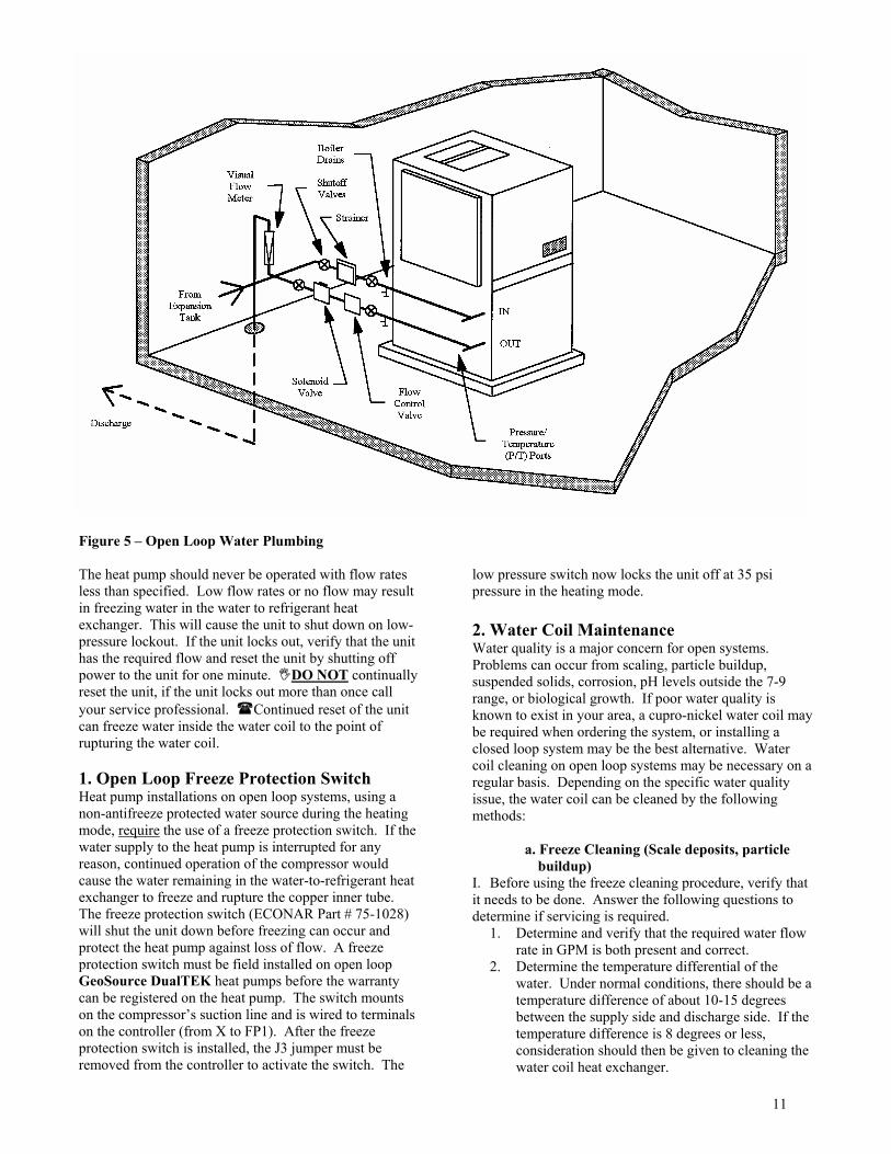
11
Figure 5 � Open Loop Water Plumbing The heat pump should never be operated with flow rates less than specified. Low flow rates or no flow may result in freezing water in the water to refrigerant heat exchanger. This will cause the unit to shut down on low-pressure lockout. If the unit locks out, verify that the unit has the required flow and reset the unit by shutting off power to the unit for one minute. #DO NOT continually reset the unit, if the unit locks out more than once call your service professional. $Continued reset of the unit can freeze water inside the water coil to the point of rupturing the water coil. 1. Open Loop Freeze Protection Switch Heat pump installations on open loop systems, using a non-antifreeze protected water source during the heating mode, require the use of a freeze protection switch. If the water supply to the heat pump is interrupted for any reason, continued operation of the compressor would cause the water remaining in the water-to-refrigerant heat exchanger to freeze and rupture the copper inner tube. The freeze protection switch (ECONAR Part # 75-1028) will shut the unit down before freezing can occur and protect the heat pump against loss of flow. A freeze protection switch must be field installed on open loop GeoSource DualTEK heat pumps before the warranty can be registered on the heat pump. The switch mounts on the compressor�s suction line and is wired to terminals on the controller (from X to FP1). After the freeze protection switch is installed, the J3 jumper must be removed from the controller to activate the switch. The
low pressure switch now locks the unit off at 35 psi pressure in the heating mode. 2. Water Coil Maintenance Water quality is a major concern for open systems. Problems can occur from scaling, particle buildup, suspended solids, corrosion, pH levels outside the 7-9 range, or biological growth. If poor water quality is known to exist in your area, a cupro-nickel water coil may be required when ordering the system, or installing a closed loop system may be the best alternative. Water coil cleaning on open loop systems may be necessary on a regular basis. Depending on the specific water quality issue, the water coil can be cleaned by the following methods:
a. Freeze Cleaning (Scale deposits, particle
buildup) I. Before using the freeze cleaning procedure, verify that it needs to be done. Answer the following questions to determine if servicing is required.
1. Determine and verify that the required water flow rate in GPM is both present and correct.
2. Determine the temperature differential of the water. Under normal conditions, there should be a temperature difference of about 10-15 degrees between the supply side and discharge side. If the temperature difference is 8 degrees or less, consideration should then be given to cleaning the water coil heat exchanger.
12
II. If cleaning of the water coil is indicated, please carefully follow the steps listed below to utilize the freeze cleaning method.
1. Turn off the heat pump and its water supply. 2. Open a plumbing connection on the water supply
side, if possible, to break the system vacuum and allow easier drainage of the system and water coil.
3. Drain the water out of the system and water coil via the boiler drains on the entering and leaving water lines, and the drain on the heat exchanger.
!WARNING!! ! FAILURE TO COMPLETELY DRAIN THE WATER COIL HEAT EXCHANGER COULD POSSIBLY RESULT IN A FREEZE RUPTURE!
4. Set the thermostat to "Heat" to start the heat pump in the heating mode and quickly freeze the coil.
5. Allow the heat pump to run until it automatically shuts off on low pressure and then turn the thermostat to the "Off" position.
6. Recap the water coil drain and tighten any plumbing connections that may have been loosened.
7. If so equipped, open the field installed drain cock on the water discharge side of the heat pump, and install a short piece of rubber hose to allow drainage into a drain or bucket. A drain cock on the discharge side allows the water flow to bypass the solenoid valve, flow valve, flow meter, or any other item that may be clogged by mineral debris. Drainage to a bucket helps prevent the clogging of drains and allows you to visually determine the effectiveness of the procedure.
8. Turn on the water supply to the heat pump in order to start the process of flushing any mineral debris from the unit.
9. Set the thermostat to "Cool" and start the heat pump in the cooling mode to quickly thaw out the water coil.
10. Run the heat pump until the water coil is completely thawed out and any loosened scale, mineral deposits, or other debris buildup is flushed completely from the water coil. Allow at least 5 minutes of operation to ensure that the water coil is thoroughly thawed out.
11. If the water still contains mineral debris, and if the flow through the unit did not improve along with an increase in the temperature difference between the water supply and discharge, repeat the entire procedure listed above.
12. Reset the heat pump for normal operation. b. Chlorine Cleaning (Bacterial Growth) 1. Turn the thermostat to the "Off" position. 2. Connect a submersible circulating pump to the
hose bibs on the entering and leaving water sides of the heat exchanger.
3. Submerse the pump in a five-gallon pail of water and chlorine bleach mixture. The chlorine should
be strong enough to kill the bacteria. Suggested initial mixture is 1 part chlorine bleach to 4 parts water.
4. Close the shut off valves upstream and downstream of the heat exchanger.
5. Open the hose bibs to allow circulation of the bleach solution.
6. Start the pump and circulate the solution through the heat exchanger for 15 minutes to one hour. The solution should change color to indicate the chlorine is killing the bacteria and removing it from the heat exchanger.
7. Flush the used solution down a drain by adding a fresh water supply to the pail. Flush until the leaving water is clear.
8. Repeat this procedure until the solution runs clear through the chlorine circulation process.
9. Flush the entire heat pump system with water. This procedure can be repeated annually, semiannually, or as often as it takes to keep bacteria out of the heat exchanger, or when bacteria appears in a visual flowmeter to the point the flow cannot be read. Another alternative to bacteria problems is to shock your entire well. Shocking your well may give longer term relief from bacteria problems than cleaning your heat exchanger, but will probably need to be repeated, possibly every three to five years. $Contact a well driller in your area for more information.
c. Miratic Acid Cleaning (Difficult Scaling and Particle Buildup Problems)
1. Consult installer due to dangerous nature of acids. 2. Iron out solutions and de-scaling products are also
useful.
VII. CONDENSATE DRAIN Condensate traps are built into every GeoSource DualTEK vertical unit, so an external trap should not be installed. Vertical units must be level to insure proper condensate drainage. Horizontal units require an external condensate trap in order to drain water from the heat pump. Horizontal units must also be mounted level in order for the condensate to drain.
Figure 6 � Condensate Drain � Horizontal Units Only

13
The condensate line as it leaves the U bend of the condensate trap must be at least 3� below the base of the heat pump. This requires the U bend to be 6� below the unit to give the upward portion of the U bend a 3� lift. The condensate trap should be vented after the U bend. The condensate line should be pitched away from the unit a minimum of 1/8� per foot. If the unit produces an odor in the cooling mode, the condensate trap or line may be plugged, or the unit may not be pitched correctly. Bleach may be poured down the condensate drain in the heat pump to kill any bacterial growth in the condensate line.
VIII. UNIT SIZING Selecting the unit capacity of a GeoSource DualTEK geothermal heat pump requires four things:
A) Earth Loop Configuration and Design Water Temperatures.
B) Hydronic Side Heat Exchanger Operating Temperatures.
C) Building Heat Loss/Heat Gain. D) Temperature Limitations.
A. Earth Loop Configuration and Design Water Temperatures Loop configurations include the open and closed loop varieties. Heat pump flow rate requirements vary depending on loop configuration (see Table 6). Consult ECONAR�s Engineering Specifications Manual for capacities at different loop entering water temperatures and hydronic leaving water temperatures. Remember to use the correction factors for GeoSource DualTEK units found in the Engineering Specifications manual. 1. Closed Loop Systems Closed loop systems use a heat exchanger of high density polyethylene pipe buried underground to supply a tempered water solution back to the heat pump. Closed loops operate at higher flow rates than open loops since the entering water temperature (EWT) is lower. The loop EWT supplied to the heat pump has a great effect on the capacity of the unit in the heating mode. Earth loops in cold climates are normally sized to supply a wintertime EWT to the heat pump from 32oF down to 25oF, which minimizes the installation cost of the earth loop and still maintains proper system operation. The GPM requirements and pressure drops for loop pump sizing are shown in Table 6. 2. Open Loop Systems On an open loop system the design water temperature will be the well water temperature in your geographic region. Many cold climates are in the 50oF range for well water temperature. If your well water temperatures are lower than 50oF, for instance Canadian well water can be as low as 43oF, the flow rate must be increased to avoid leaving water temperatures below the freezing point. If well water temperatures are above 50oF, as in some southern
states where well water temperatures are above 70oF, the flow rates may need to be increased to dump heat more efficiently in the cooling mode. Varying well water temperatures will have little effect on unit capacity in the cooling mode (since the well is connected to the heat pump condenser), but can have large effects on the capacity in the heating mode (since the well is connected to the evaporator). If well water temperatures are to exceed 70oF, special considerations, such as closed loop systems, should be addressed. B. Hydronic Side Heat Exchanger Operating Temperatures The hydronic side heat exchangers discussed in section IV are designed to operate at a specific fluid supply temperature. This operating temperature will have to be supplied to the selected space conditioning heat exchanger by the heat pump. The manufacturers or distributors of the hydronic side heat exchangers publish the capacity of their equipment at different operating temperatures and fluid flow rates. These capacities and operating temperatures are required to select the heat pump to be used in the system. When sizing the hydronic side of the GeoSource DualTEK heat pump, remember to use the minimum hydronic loop temperature that will supply the necessary heating capacity to the conditioned space. If an intermediate heat exchanger is used between the closed hydronic loop and the open hydronic loop as pictured in Figure 3, expect a 10oF operating temperature difference between the two circuits. For example, if the direct coupled storage tank is at 120oF, expect the maximum operating temperature of the open circuit connected through an intermediate heat exchanger to be 110oF. This occurs when connecting open loop applications to the closed loop systems with plate heat exchangers or with indirect water heaters. C. Building Heat Loss/Heat Gain The space load must be estimated accurately for any successful HVAC installation. There are many guides or computer programs available for load estimation including the ECONAR GeoSource Heat Pump Handbook, Manual J, and others. After the heat loss/heat gain is completed, loop EWT�s are established, and hydronic side heat exchanger conditions are determined, the heat pump can now be selected using the hydronic and forced air heat pump data found in the Engineering Specifications. Remember to use the correction factors for the GeoSource DualTEK models that are listed in the Engineering Specifications manual. Choose the capacity of the heat pump based on both the forced air heating and cooling loads, and the hydronic heating load.

14
D. Temperature Limitations Be aware of the operating range of the geothermal system when sizing the particular heat pump. An operating range of 15oF (minimum for heating) to 110oF (maximum for cooling) is required for the earth loop side. These limits have been established based on efficiency limitations and safety pressure switch limits (25-psi low-pressure cutout and 400-psi high-pressure cutout). Hydronic side limitations have a minimum of 50oF hydronic entering water temperature and a maximum of 130oF hydronic leaving water temperature range (entering water to the hydronic side below 50oF gives low head pressures that drives the suction pressure below cutout conditions).
IX. ELECTRICAL SERVICE The main electrical service must be protected by a fuse or circuit breaker, and be capable of providing the amperes required by the unit at nameplate voltage. All wiring shall comply with the national electrical code and/or any local codes that may apply. Access to the line voltage contactor is gained through the knockouts provided on either side of the heat pump next to the front corner. Route EMT or flexible conduit with appropriate 3-conductor wire to the contactor. !WARNING - The unit must be properly grounded!! #CAUTION: Three-phase units MUST be wired properly to insure proper compressor rotation. Improper phasing may result in compressor damage. An electronic phase sequence indicator must be used to check supply-wiring phase. Also, the �Wild� leg of the three-phase power must be connected to the middle leg on the contactor. When supplying power to external water pumps with the heat pump�s power supply, use only impedance protected motors. An ECONAR PumpPAK can be wired directly to the contactor and grounded in the grounding lug. A relay (M6) and terminal block (BP) is supplied in the electrical box for the hydronic side pump. The relay will start the pump with a call from the aquastat. The use of impedance protected pumps eliminates the need for additional fusing. Do not connect more than a 1/3 horsepower pump to the internal pump relay. If larger pumps are required, a separate power supply is required to supply the pump. To start this pump use a 24-volt relay pulled in from the Y and X terminals.
X. 24 VOLT CONTROL CIRCUIT The wiring diagrams in Figures 8 and 9 shows the low voltage controls of the heat pump and some generic external control schemes. This section will break down
the three basic components of the low voltage circuit; transformer, thermostat/aquastat, and controller. A. Transformer Electrical diagrams are provided in Figures 8 and 9, and on the electrical box cover panel of the heat pump. An internal 24-volt, 75 VA transformer is provided to operate all control features of the heat pump. Even though the 75 VA transformer is larger than the industry standard 40 VA transformer, it can still be overloaded quickly when using it for control equipment like zone valves or zone circulators. Table 7 shows the transformer usage for the GeoSource DualTEK heat pumps. Table 7 � Transformer Usage (VA)
Component VA Contactor 7 Pump Relay 3 Blower Relay 6 Reversing Valve 4 Controller 1 Thermostat 1 Solenoid Valve 33 Total 55 VA Available 20 VA
If the system�s external controls require more than the VA available for external use from the transformer, an external transformer must be used. You can see that in Figure 2, the heat pump�s internal transformer can easily power the external 24-Volt system. In contrast, if a system contains components that have their own power supply, they must be coupled to the heat pump. This can be accomplished using an isolation relay which isolates the external systems power supply from the heat pump�s transformer (e.g. use the external systems independent power supply to energize the coil of a relay, passing a signal across the Normally Open contacts from the heat pump's transformer). The heat pump's transformer can generally power simpler control systems consisting of a few relays or zone valves (depending, of course, on the VA draw of the components). On more complicated control systems the transformers capacity is used up very quickly. "Note: For units operating on 208V electrical service, the transformer must be switched to the correct lead (see electrical diagrams � Figures 8 and 9). Units are factory shipped with the transformer set for 240V service. Operating a unit on 208V with the transformer set to 240V will cause the unit to operate with less than normal control voltage. B. Thermostat/Aquastat Consult the instructions in the thermostat box for proper mounting and thermostat operation.

15
# CAUTION- miswiring of control voltage on system controls can result in transformer burnout. "Note: If a single thermostat controls multiple heat pumps, the control wiring of the heat pumps must be isolated from each other. This will prevent the heat pumps from receiving high voltage through the common wiring if it is turned off at the circuit breaker for service. A GeoSource DualTEK heat pump requires at least two thermostats. The first thermostat is a forced air heat pump thermostat connected to the terminal strip on the controller. This thermostat controls forced air heating and cooling as any thermostat would. The second thermostat is a heating aquastat, which is wired to H and R on the terminal strip. The aquastat tells the heat pump when hydronic side water heating is required and when the hydronic side is satisfied. The heat pump can only run in one mode at a time, so there is a priority switch on the controller to regulate mode changes (see Forced Air/Hydronic Priority). Power is supplied to the thermostat by connecting the R and X terminals to the heat pump terminal strip. The G terminal energizes the blower relay. The Y terminal energizes the compressor for forced air heating and cooling. The unit is put into the cooling mode when the thermostat energizes the O terminal, which operates the 4-way reversing valve. The L terminal is used to power a lockout LED on the thermostat, which indicates a compressor lockout. The heat pump�s controller regulates compressor operation when there is an auxiliary heat (W2) or an emergency heat (E) call from the thermostat. With forced air priority, a W2 call will energize the elements, along with the blower and compressor in forced air. With hydronic priority, if the unit is running in hydronic mode and receives a W2 call, the blower and electric elements will energize along with the compressor in hydronic mode. During emergency heating, the compressor will be shut down, and not allowed to run. When a single stage electric heater is used, wire it to the W2 and X terminals on the left terminal strip on the controller. Also, wire E and W2 from the thermostat to the heat pump. This will cause the electric heater to energize when the thermostat gives an emergency heat or second stage heat call. The aquastat closes and passes power to the H terminal, energizing the compressor and circulation pumps in the hydronic heating mode. The pump relay is connected to the circulation pump's 3 pole, high voltage terminal block (BP). The hydronic side circulation pump receives power from BP, which is energized by M6. When mounting an aquastat inside a storage tank, always use a submersible type aquastat. The aquastat should be installed
approximately 1/3 of the way down into the tank. Set the aquastat differential to 15oF to avoid short cycling "Note: The aquastat should be set to give a maximum leaving water temperature from the heat pump of 115oF. This means that the actual setting of the aquastat will be lower than this (typically 100 to 105oF). Any number or types of thermostats, aquastats, or switches can be used with an independent power supply (typically a 24-volt transformer) to activate specific zone controls. These zone controls are normally either zone pumps (Figure 3) or zone valves (Figure 1). End switches on the zone valves can be used to pass a signal to a pump relay when the zone valve is open. The pump relay then activates a common pump, which supplies any number of zones. If a thermostat is equipped with an anticipator it should be set to its maximum setting to avoid interfering with heat pump operation. The anticipator is a resistor in the thermostat that heats up as current is drawn through and satisfies the thermostat prematurely. This reduces system capacity by restricting run time. C. Controller The controller receives a signal from the thermostat and initiates the correct sequence of operations for the heat pump. The controller performs the following functions:
1) Blower Operation 2) Earth Loop Pump Initiation 3) Compressor Operation 4) 4-Way Valve Control 5) Compressor Lockouts 6) Compressor Anti-Short-Cycle 7) System Diagnostics 8) Forced Air/Hydronic Priority 9) Overflow Detection
1. Blower Operation A signal on the G terminal from the thermostat to the controller will tell the controller to energize the blower. The controller then energizes its M7 output to send control voltage directly to the blower motor relay. To change blower speeds, move the wire on the fan terminal strip to the desired setting. Changing the speed from the factory setting can cause problems with output air temperature or reduced airflow, locking out the unit. For more information on the blower, including the optional ECM Variable Speed Blower (-DxVx), see section III, Duct System/Blower. 2. Earth Loop Pump Initiation If a PumpPAK is used, it should be wired directly to the contactor of the compressor. If a PumpPAK is not used, a separate pump can be used which is energized with a pump relay (Note: electrical code will require a
16
fused disconnect for pumps other than PumpPAKs). When there is a call for an M1 output from the controller, the contactor will energize, starting the compressor and earth loop pump. 3. Compressor Operation A Y signal from the thermostat will tell the controller to initiate forced air heating or cooling. The controller then decides, based on lockouts, anti-short-cycle periods, and priorities, when to bring the compressor on. The M1 output of the controller energizes the compressor. The compressor stays on until either the thermostat is satisfied, the aquastat calls for hydronic heating with hydronic priority, or a lockout condition occurs. An H signal from the aquastat will tell the controller to start in hydronic heating mode. Depending on lockouts, anti-short-cycle periods and priorities, the controller will send an M1 signal to start the compressor. The compressor will stay running in hydronic mode until the aquastat is satisfied, the thermostat calls for forced air heating or cooling with forced air priority, or a lockout condition occurs. 4. 4-Way Valve Control The controller energizes the 4-way reversing valves to direct the flow of refrigerant. When the unit is running in forced air cooling, the controller energizes its M3 output to send control power to the cooling reversing valve (VR1), to switch the refrigerant circuit to the cooling mode. When the unit is running in hydronic heating mode, the controller energizes its M4 output to send control power to the hydronic reversing valve (VR2), to switch the refrigerant circuit to the hydronic mode. 5. Compressor Lockouts A compressor lockout occurs if the high-pressure, low pressure, or freeze protection pressure switches open. The controller blocks the signal from the thermostat or aquastat to the contactor that normally would energize the compressor. In the event of a compressor lockout the controller will send a signal from L on the terminal strip to an LED on the thermostat to indicate a lockout condition. On GeoSource DualTEK units, if the heat pump locks out in either the forced air or hydronic mode, the controller will let the other mode run until that mode also locks out. For example, if a problem with the hydronic loop causes the heat pump to lock out on one of the pressure switches, the heat pump will still be able to run in forced air mode. If the heat pump then locks out while it is in the forced air mode, the unit will not come on in either mode. A lockout condition means that the unit has shut itself down to protect itself. The unit will have to be shut off at the circuit breaker for one minute to reset the controller.
Problems that could cause a lockout situation include: a. Water flow or temperature problems b. Air flow or temperature problems c. Internal heat pump operation problems d. Cold ambient air temperature conditions
$If a lockout condition exists, the heat pump should not be reset more than once; a service technician should be called immediately. #The cause of the lockout must be determined. Repeated reset may cause damage to the system. 6. Compressor Anti-Short-Cycle An anti-short-cycle is a delay period between the time a compressor shuts down and when it is allowed to come on again. This protects the compressor and avoids nuisance lockout conditions. Anti-short-cycles occur after these four conditions;
1) A one to two minute time-out period occurs on the compressor before it will start after its last shutdown.
2) A four minute 35 second delay is incorporated into the timing function immediately after power is applied to the heat pump. This occurs only after reapplying power to the unit. To avoid this timeout while servicing the unit, apply power, disconnect and reapply power very quickly. This can sometimes eliminate the waiting period.
3) A 30 second to one minute anti-short-cycle will occur after a low-pressure switch opens in the cooling mode. This is done to eliminate nuisance lockout conditions. If the compressor continuously short cycles in the cooling mode, shut the thermostat off and call your service technician.
4) A one to two minute anti-short-cycle occurs when switching between forced air and hydronic modes.
7. System Diagnostics The controller is equipped with diagnostic LED lights which indicate the system status at any particular time. The lights indicate the following conditions: a. 24 Volt system power GREEN b. Fault or Lockout RED c. Anti-short-cycle mode RED d. Forced Air Compressor operation RED e. Hydronic Compressor operation RED f. Pressure switch status on lockout YELLOW g. Controller outputs (M1 thru M10) RED h. Condensate overflow (optional) RED 8. Forced Air/Hydronic Priority Dip Switch #1 on the controller decides forced air/ hydronic priority. When the dip switch is in the ON position (factory preset), the forced air mode has priority over hydronic mode. This means that if the heat pump is running in the hydronic mode, and the thermostat gives a
17
call for forced air, the heat pump will shut down for an anti-short-cycle period, and then run in the forced air mode until the thermostat is satisfied. At that time, if the aquastat is still calling for hydronic heating, the heat pump will start again in the hydronic mode after an anti-short-cycle. If Dip Switch #1 is set to the OFF position, hydronic heating has the priority over forced air heating or cooling. 9. Overflow Detection An optional overflow detection sensor may be added to the GeoSource DualTEK heat pumps. This sensor is located in the drain pan, and monitors the amount of water accumulated in the pan. If the condensate drain becomes clogged or kinked, and the unit is not draining water, the sensor will shut the heat pump off in forced air cooling for an anti-short-cycle period of approximately 3 minutes and 35 seconds. After this time, the heat pump will start again if the condensate has drained. If the water is still present, the unit will go through anti-short-cycles until the condensate has drained. This protection switch keeps the condensate from overflowing the drain pan and possibly leaking onto the floor or ceiling.
XI. STARTUP Before applying power to the heat pump, check the following items: - Water supply plumbing to the heat pump is
completed and operating. Manually open the water valve on well systems to check flow. Make sure all valves are open and air has been purged from a loop system. Never operate the system without correct water supply.
- All construction dust has been cleaned up and all sheet-rocking is completed. Construction dust, especially sheet-rock dust, can plug the air coil and block airflow. Make sure the filter is clean before starting the unit.
- Low voltage wiring of the thermostat and any additional control wiring is complete. Set thermostat to the �OFF� position.
- All high voltage wiring is correct including fuses, breakers, and wire sizes.
- The heat pump is located in a warm area (above 45oF). Starting the system with low ambient temperature conditions is more difficult; do not leave the area until the space is brought up to operating temperatures.
- Hydronic side water temperatures are warm enough (50oF or above) to start in the heating mode.
- The hydronic side water flow rate is correct (shown in Table 5). Low water temperature starting may require flow reduction until the system is up to operating temperature.
You may now apply power to the unit. A 4 minute 35 second delay on power up is programmed into the heat
pump before the compressor will operate. During this time the pump relay will energize the hydronic side-circulating pump, if the aquastat is calling for heat. Verify that the flow rate and temperature of the hydronic side flow are at the recommended levels. Also, during this time, you can verify airflow with the following procedure: - Place the thermostat in the �FAN ON� position. The
blower should start immediately. Check airflow at the registers to make sure that they are open and that air is being distributed throughout the house. When airflow has been checked, move the thermostat to the �FAN AUTO� position. The blower should stop.
The following steps will assure that your system is heating and cooling properly. After the initial time-out period is completed, the red ASC indicator light on the controller will shut off. The heat pump is now ready for operation. - Turn the thermostat up to its highest temperature
setting. Place the thermostat to the "HEAT" position. The blower will start. The compressor should start 1 to 2 seconds later. If an electronic thermostat is used it may cause its own compressor delay at this time, but the compressor will come on after the time-out period.
- After the unit has run for 5 minutes, check the return and supply air temperatures. An air temperature rise of 25oF to 35oF is normal in the heating mode, but variations in water temperature and water flow rate can cause variations outside the normal range.
- Turn the thermostat to the �OFF� position. The compressor and blower will shut down in 1 to 2 seconds.
- Next, turn the thermostat down to its lowest setting. Place the thermostat in the "COOL" position. The blower will start. The compressor will start after an anti-short-cycle period from its last shutdown. The anti-short-cycle period is indicated by the red light on the controller.
- After the unit has run for 5 minutes, check the return and supply air temperatures. An air temperature drop of 15oF to 20oF is normal in the cooling mode but factors mentioned in the heating section can also effect temperature drop.
- Set the thermostat to the OFF position, and set the aquastat to heat at its highest setting.
- After an anti-short-cycle period, the compressor will come on.
- After the unit has run in the hydronic mode for 5 minutes, check the hydronic side return and supply water temperatures. A water temperature rise of 10oF to 15oF is normal, but variations in entering water temperatures and water flow rates can cause variations.
- Set the thermostat for normal operation. - Instruct the owner on correct operation of the
thermostat, aquastat, and heat pump system. The unit is now operational.

18
The heat pump is equipped with both high and low pressure switches that shut the unit off if the refrigerant pressure exceeds 400 psi or goes below 25 psi. If the system exceeds 400 psi, the high-pressure switch will trip and lock the unit off until power has been disconnected at the circuit breaker for approximately one minute. System pressures below 25 psi in the heating mode will trip the low pressure switch and lock the unit out until the power supply has been de-energized for one minute. On a well water system, the freeze protection switch (field installed part number 75-1028) will activate the lockout at 35 psi in the heating mode to protect the water coil against freeze rupture. After resetting a lockout (by disconnecting power to the unit) verify that water flow is at the recommended levels before energizing the compressor. DO NOT reset a well water system without verifying water flow. DO NOT reset the system more than once. #Repeated resetting of the lockout can cause serious damage if the reason for lockout is not corrected. ! - If lockout occurs more than once contact your ECONAR dealer immediately. $
XII. SERVICE Regular service to a GeoSource DualTEK heat pump is very limited. The biggest factor is changing the air filter. Other factors could include water coil maintenance on an open loop system (this maintenance is discussed in section VI). Setting up regular service checkups with your ECONAR dealer could be considered. Any major problems with the heat pump system operation will be indicated on the thermostat lockout light. A. Filter The GeoSource DualTEK heat pump is equipped with a disposable air filter. This filter should normally be replaced once a month during normal usage. During extreme usage or if system performance has decreased, the filter should be replaced more often. A dirty filter will reduce the airflow to the system. This decrease in airflow will reduce the efficiency and comfort level of the system. In the heating mode, reduced airflow may increase the cost of operation and, in extreme cases, cause system lockout due to high refrigerant pressures. In the cooling mode, reduced airflow may reduce cooling capacity and in extreme cases ice the aircoil over, causing system shutdown due to low refrigerant pressures. If another filter is used in place of the factory specified filter, it should also be cleaned or replaced in a timely manner. Be careful in selecting optional filters so that excessive external resistance to airflow is not induced. B. Lockout Lights A lockout light on the thermostat will light to indicate major system problems. If lockout occurs, follow the procedure below:
1) Check for a clean filter and correct water supply from the earth loop or well water system.
2) Reset the system by disconnecting power at the circuit breaker for one minute, and then reapplying power.
3) If shutdown reoccurs, check the indicator lights on the controller in the unit and review the lockout troubleshooting guide in section XIV of this manual.
4) $If lockouts persist, call your ECONAR dealer. Do not continuously reset the lockout condition or damage may occur.
C. Preseason Inspection Before each season, the air coil, drain pan, and condensate drain should be inspected and cleaned as follows: - Turn off circuit breakers. - Remove access panels. - Clean air coil by vacuuming it with a soft-brush
attachment. - Remove any foreign matter from the drain pan. - Flush pan and drain tube with clear water. - Replace access panels and return power to the unit.
XIII. THERMOSTAT OPERATION
This section covers basic operation of the standard 2-heat 1-cool thermostat that ECONAR carries. This thermostat is ECONAR part number 70-2002, Honeywell part number T8511G. If your thermostat is a different style, please refer to the instructions supplied with that thermostat. The settings of the thermostat are controlled with the �System�, �Fan�, �i�, up key, and down key buttons. The System and Fan buttons are located behind the flip-down panel. By pressing the �System� button, you can control the mode that the thermostat operates in. The five system settings are:
1. Em. Heat � Controls backup heating. In this mode, the heat pump�s compressor is locked out, and only the backup heating elements (if installed) operate.
2. Heat � Controls normal heating operation. 3. Off � Both heating and cooling are off. 4. Cool � Controls normal cooling operation. 5. Auto � The thermostat automatically changes
between heating and cooling operation, depending on the indoor temperature.
Note: When the thermostat is set to Auto, there must be at least a 2oF difference between the Heating setpoint temperature and the Cooling setpoint temperature. The �Fan� button controls the operation of the heat pump�s blower. The Fan button has two settings:
1. On � The blower operates continuously.

19
2. Auto � The blower operates with either a heating or cooling call.
By pressing the �i�, or information, key, you can cycle through your temperature setpoints. If you wish to change a temperature setting, press either the up key or down key when the appropriate mode is displayed. For example, you wish to change the heating setpoint from 68oF to 70oF. Push the �i� key until the heating setpoint appears on the LCD display. Then, press the up key until the desired setpoint is reached. The thermostat will
automatically switch back to the room temperature display after a few seconds. If the LED on the bottom of the thermostat is lit, your heat pump has locked itself out to protect itself. If this occurs, please see the Compressor Lockout section of this manual. If you have additional questions about your thermostat, please see the installation manual that was sent with the thermostat.
XIV. TROUBLESHOOTING GUIDE FOR UNIT OPERATION PROBLEM POSSIBLE CAUSE CHECKS AND CORRECTIONS
Blown Fuse/Tripped Replace fuse or reset circuit breaker. (Check for correct size Circuit Breaker fuse and circuit breaker.) Blown Fuse on Controller Replace fuse on controller. (Check for correct size fuse.) Broken or Loose Wires Replace or tighten the wires Voltage Supply Low If voltage is below minimum voltage on data plate, contact local power company. Low Voltage Circuit Check 24 volt transformer for burnout or voltage less than 18
Entire unit does volts. not run. Thermostat Set thermostat on "Cool" and lowest temperature setting, unit
should run. Set thermostat on "Heat" and highest temperature setting, unit should run. If unit does not run in both cases, the thermostat could be wired incorrectly or be faulty. To prove faulty or miswired thermostat, disconnect thermostat wires at the unit and jumper between "R", "Y", and "G" terminals and unit should run. Replace thermostat with correct heat pump thermostat only.
A substitute may not work properly. Interruptible Power Check incoming supply voltage. Thermostat Check setting, calibration, and wiring. If thermostat has an anticipator, set it at 1.0 or 1.2. Wiring Check for loose or broken wires at compressor, capacitor, or contactor.
Blown Fuse Replace fuse or reset circuit breaker. (Check for correct size fuse or circuit breaker.) High or Low Pressure The unit could be off on the high or low pressure cutout control. Controls Check water GPM, air CFM and filter, ambient temperature and loss of refrigerant. If the unit still fails to run, check for faulty pressure controls individually. Replace if defective. Defective Capacitor Check capacitor. If defective; remove, replace, and rewire correctly.
Blower motor Voltage Supply Low If voltage is below minimum voltage specified on the data plate, runs but contact local power company. Check voltage at compressor for
compressor possible open terminal. does not, or Low Voltage Circuit Check 24 volt transformer for burnout or voltage less than 18 compressor volts. With a voltmeter, check signal from thermostat at Y to X, short cycles. M1 on controller to R, and the capacitor voltage drop. Replace
component that does not energize. Compressor Overload In all cases an "internal" compressor overload is used. If the
Open compressor motor is too hot, the overload will not reset until the compressor cools down. If the compressor is cool and the overload does not reset, there may be a defective or open overload. Replace the compressor.

20
PROBLEM POSSIBLE CAUSE CHECKS AND CORRECTIONS Compressor Motor Internal winding grounded to the compressor shell. Replace the Grounded compressor. If compressor burnout occurs, install filter drier at suction line.
Blower motor Compressor Windings Check continuity or the compressor windings with an ohmmeter. runs but no Open If the windings are open, replace the compressor. compressor Seized Compressor Try an auxiliary capacitor in parallel with the run capacitor
(Cont.) momentarily. If the compressor still does not start, replace it. Thermostat The differential is set too close to the thermostat. Readjust heat anticipator to 1.0 or 1.2. Thermostat Improperly located thermostat (e.g. near kitchen), inaccurately
Unit Short sensing the comfort level in the living area. Cycles Aquastat The differential is set to close on aquastat. Increase differential setting to
15oF. Wiring and Controls Loose wiring connections, or control contactor defective.
Compressor Overload Defective compressor overload, check and replace if necessary. If the compressor runs too hot, it may be due to a insufficient refrigerant charge. Water Lack of sufficient pressure, temperature, and/or quantity of water. Unit Undersized Recalculate heat gains or losses for space to be conditioned. If excessive, rectify by adding insulation, shading, etc. Loss of Conditioned Air Check for leaks in ductwork or introduction of ambient air through by Leaks doors and windows. Thermostat Improperly located thermostat (e.g. near kitchen), inaccurately sensing the comfort level in the living area. Check anticipator setting. Airflow Lack of adequate airflow or improper distribution of air. Check the
Insufficient motor speed or duct sizing. Check the filter, it should be inspected cooling or every month and changed if dirty. Remove or add resistance heating. accordingly.
Refrigerant Charge Low on refrigerant charge causing inefficient operation. Adjust only after checking CFM and GPM. Compressor Check for defective compressor. If discharge pressure is too low and suction pressure is too high, compressor is not pumping properly. Replace compressor. Reversing Valve Defective reversing valve creating bypass of refrigerant from discharge to suction side of compressor. When it is necessary to replace the reversing valve, wrap it with a wet cloth and direct heat away. Excessive heat can damage the valve. Desuperheater The desuperheater circuit (in-line fuse) should be disconnected during cold weather to allow full heating load to the house. Dirty Filter Check filter. Clean or replace if found dirty. Thermostat Improperly Set Check if thermostat is set at correct temperature.
Unit will not Defective Thermostat Check thermostat operation. Replace if found defective. operate on Incorrect Wiring Check for broken, loose, or incorrect wires. "heating" Blower Motor Defective Check blower motor in one of the other switch positions. If it does
not operate, check for open overload. If overload is open and motor is not overheated, replace it. Aquastat Set too High Heat pump is trying to heat hot water to too hot of a temperature (over
120oF). Reduce aquastat setpoint. (Heats only) will not move. Switch from heating to cooling a few times to loosen
valve.

21
PROBLEM POSSIBLE CAUSE CHECKS AND CORRECTIONS
Reversing Valve Does Not Shift
Defective solenoid valve does not energize. Replace solenoid coil
Unit does not Reversing Valve Does Not The solenoid valve is de-energized due to miswiring at the unit or cool Shift, the Valve is Stuck. thermostat--correct wiring. Replace if valve is tight or frozen and
(Heats only) will not move. Switch from heating to cooling a few times to loosen valve. Dirty Air Filter Check filter. Clean or replace if found dirty. Airflow Lack of adequate airflow or improper distribution of air. Check the motor speed and duct sizing. Check the filter, it should be inspected
Evaporator every month and changed if dirty. Check for closed registers. (air coil) Remove or add resistance accordingly. ices over Evaporator Blower Motor Check for overheated evaporator blower motor and tripped
Tripping Off on Overload overload. Replace motor if necessary. Unit Operating at Too Low If room temperature drops below 65 degrees, the evaporator may a Room Temperature ice over. Unit Not Level or Pitched Level vertical units, and horizontal units which use bottom condensate
Water drips Correctly drain. Pitch horizontal units that use side condensate drain. from unit Condensate Drain Line Clean condensate drain.
Kinked or Plugged Compressor Make sure the compressor is not in direct contact with the base or sides of the cabinet. Cold surroundings can cause liquid slugging. Increase ambient temperature. Blower and Blower Motor Blower wheel hitting the casing. Adjust for clearance and alignment. Bent blower, check and replace if damaged. Loose blower wheel on shaft, check and tighten. Defective bearings, check and replace.
Noisy Contactors A clattering or humming noise in the contactor could be due to Operation control voltage less than 18 volts. Check for low supply voltage,
low transformer output, or extra long runs of thermostat wires. If the contacts are pitted or corroded , or coil is defective, repair or replace. Rattles and Vibrations Check for loose screws, panels, or internal components. Tighten and secure. Copper piping could be hitting the metal surfaces. Carefully readjust by bending slightly. Water and Airborne Undersized ductwork will cause high airflow velocities and noisy Noises operation. Excessive water through the water-cooled heat exchanger will cause a squealing sound. Check the water flow to ensure adequate flow for good operation, while eliminating the noise.

22
XV. TROUBLESHOOTING GUIDE FOR LOCKOUT CONDITIONS If the heat pump goes into lockout on a high or low pressure switch, the cause of the lockout can be narrowed down by knowing the operating mode and which pressure switch the unit locked out on. The following table will help track down the problem once this information is known. NOTE: A lockout condition is a result of the heat pump shutting itself off to protect itself. Never bypass the lockout circuit. Serious damage can be caused by the system operating without lockout protection.
MODE LOCKOUT CONDITION POSSIBLE CAUSE High Pressure (Head) -Loss/lack of airflow through air coil (dirty air filter, closed vents, (Condenser/Air Side) blower, restricted ductwork, etc.)
-High air temperature entering heat pump -Dirty (fouled) air coil
Heating -Extremely high water temperature to the evaporator, raising compressor capacity and overloading condenser
-Loss/lack of flow through hydronic heat exchanger -High fluid temperature operation in the hydronic loop -Overcharged refrigerant circuit
Low Pressure (Suction) -Loss/lack of flow through earth coupled coil (Evaporator/Earth -Low fluid temperature operation in the earth loop Coupled Side) -Freezing fluid in heat exchanger (lack of antifreeze) -Undercharged/overcharged refrigerant circuit -Expansion valve/sensing bulb malfunction
-Low fluid temperature operation in the hydronic loop High Pressure (Head) -Loss/lack of water flow in earth loop (Condenser/Earth -High fluid temperature operation in the earth loop
Coupled Side) -Dirty (fouled) condenser coil Cooling -Overcharged refrigerant circuit
Low Pressure (Suction) -Loss/lack of airflow through air coil (dirty filter, closed vents, (Evaporator/Air Side) blower, restricted ductwork, etc.) -Low air temperature entering the heat pump (thermostat setpoint too low, etc.) -Air coil freezing up (low airflow, lack of charge, etc.) -Undercharged/overcharged refrigerant circuit -Expansion valve/sensing bulb malfunction
XVI. ADDITIONAL FIGURES AND TABLES
Figure 7 � Horizontal Unit Hanging Bracket

23
Figure 8 � Wiring Diagram for GeoSource DualTEK Heat Pump [G(V,H)xxx-x-Dx0x]

24
Figure 9 � Wiring Diagram for GeoSource DualTEK Heat Pump with Variable Speed Blower [G(V,H)xxx-x-DxVx]

25
Outdoor Swimming Pool Heat Pump Sizing Worksheet
For In-ground Pool Applications Project Name: Date:
1) Pool Length in Ft. 2) Pool Width in Ft. ======> 4) Pool Surface Area in Sq. Ft. 3) Average Pool Depth in Ft. ======> 5) Pool Volume in Cu. Ft.
6) Pool Volume in U.S. Gallons
7) Calculated Pounds of Water to be Heated. Initial Maintain
8) Desired Pool Water Temperature in oF 80 80 9) Starting Pool Water Temperature in oF 10) Average Ambient Air Temperature in oF 11) Calculated Water Temperature Difference in oF 12) Calculated Air Temperature Difference in oF
13) Initial BTU's to Heat the Pool Water with no Surface Heat Loss 14) Hours Allowed to Heat the Pool Water to Desired Temperature 120 15) Initial BTU/hr Needed to Heat Pool Water in Time Allowed 16) Average Wind Speed Factor (see below) 17) Heat Loss from Pool Surface in BTU/hr
18) Total BTU/hr Required to Heat & Maintain Pool Water Temperature
Instructions, Assumptions, and Additional Notes A) Enter the appropriate pool dimensions where requested on lined 1, 2, and 3. If the pool depth is not constant,
please enter the overall average depth. If the pool is not rectangular in shape, please move on to the next step. B) Calculate lines 4, 5, and 6 after lines 1-3 are filled in. There are 7.48 Gal Water per Cu. Ft. If the pool is not
rectangular in shape, such as elliptical, oval, & kidney shapes, manually calculate the information needed for lines 4 and 5 and enter the results in the appropriate boxes where requested on these lines.
C) Line 7: There are 62.42 Lb. Water per Cu. Ft., and 8.34 Lb. Water per U.S. Gallon. D) Enter the desired pool temperature in both boxes on line 8. If this temperature is not known, 80oF is a good
default to use. E) Enter the initial pool water temperature in the box on line 9. Generally, this will not be any colder than average
well water temperature (approximately 50oF.) F) Enter the average ambient outdoor air temperature for the coldest month that the swimming pool will be in use
in the box on line 10. G) Line 13: Use the following equation to calculate the initial BTU's required to heat the pool without any
consideration to time or to surface heat loss via convection. Initial BTU's = 1.0 [BTU/LB*oF] x Line 7 x Line 11
H) Line 14: Enter the amount of time in hours that will be allowed to initially heat the pool. (4 to 5 days [120 hours] is normally acceptable and economical for private pools.)
I) Line 15: Calculates the heating capacity (BTU/hr) required to initially heat the pool. Heating Capacity [BTU/hr] = Line 13 / Line 14
J) Line 16: Enter the average wind speed correction factor as listed below. (typically 3-5 MPH) (<3 MPH = .75, 3 to 5 MPH = 1.0, 5 to 10 MPH = 1.25, >10 MPH = 2)
K) Line 17: Calculate the BTU/hr heat loss from the surface of the pool due to convection. Convection Losses [BTU/hr] = 10.5 [BTU/hr*Sq Ft*oF] x Line 4 x Line 12 x Line 16 The greatest heat loss (typically 50-60%) in a swimming pool is through evaporation. Radiation and evaporative losses can be reduced 50% through the use of a pool cover. Solar gains in unshaded pools can add up to 100,000 BTU/hr which offsets some convective loss. Because of these solar gains and economic reasons, total heating capacity for only one half of the convective losses are required when sizing. Heat loss by conduction through pool is minimal in an in-ground pool. Conduction losses for above ground pools can be compensated for by the average wind speed correction factor.
L) Line 18: Total BTU/hr = Lines 15 + (Line 17 x 1/2) Appendix 1 � Outdoor Swimming Pool Heat Pump Sizing Worksheet
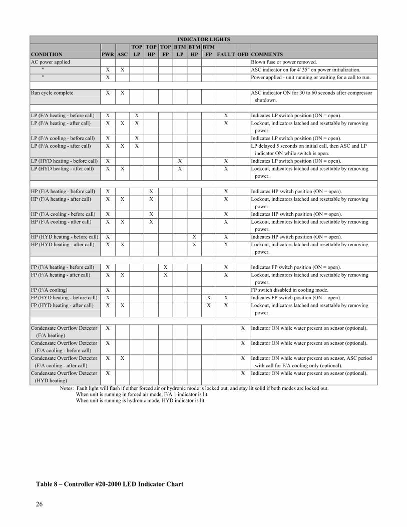
26
INDICATOR LIGHTS TOP TOP TOP BTM BTM BTM CONDITION PWR ASC LP HP FP LP HP FP FAULT OFD COMMENTS AC power applied Blown fuse or power removed. " X X ASC indicator on for 4' 35" on power initialization. " X Power applied - unit running or waiting for a call to run.
Run cycle complete X X ASC indicator ON for 30 to 60 seconds after compressor
shutdown.
LP (F/A heating - before call) X X X Indicates LP switch position (ON = open). LP (F/A heating - after call) X X X X Lockout, indicators latched and resettable by removing power. LP (F/A cooling - before call) X X Indicates LP switch position (ON = open). LP (F/A cooling - after call) X X X LP delayed 5 seconds on initial call, then ASC and LP
indicator ON while switch is open. LP (HYD heating - before call) X X X Indicates LP switch position (ON = open). LP (HYD heating - after call) X X X X Lockout, indicators latched and resettable by removing
power.
HP (F/A heating - before call) X X X Indicates HP switch position (ON = open). HP (F/A heating - after call) X X X X Lockout, indicators latched and resettable by removing power. HP (F/A cooling - before call) X X X Indicates HP switch position (ON = open). HP (F/A cooling - after call) X X X X Lockout, indicators latched and resettable by removing power. HP (HYD heating - before call) X X X Indicates HP switch position (ON = open). HP (HYD heating - after call) X X X X Lockout, indicators latched and resettable by removing
power.
FP (F/A heating - before call) X X X Indicates FP switch position (ON = open). FP (F/A heating - after call) X X X X Lockout, indicators latched and resettable by removing power. FP (F/A cooling) X FP switch disabled in cooling mode. FP (HYD heating - before call) X X X Indicates FP switch position (ON = open). FP (HYD heating - after call) X X X X Lockout, indicators latched and resettable by removing
power.
Condensate Overflow Detector X X Indicator ON while water present on sensor (optional). (F/A heating) Condensate Overflow Detector X X Indicator ON while water present on sensor (optional). (F/A cooling - before call) Condensate Overflow Detector X X X Indicator ON while water present on sensor, ASC period (F/A cooling - after call) with call for F/A cooling only (optional). Condensate Overflow Detector X X Indicator ON while water present on sensor (optional). (HYD heating)
Notes: Fault light will flash if either forced air or hydronic mode is locked out, and stay lit solid if both modes are locked out. When unit is running in forced air mode, F/A 1 indicator is lit. When unit is running is hydronic mode, HYD indicator is lit.
Table 8 � Controller #20-2000 LED Indicator Chart

XVII. DESUPERHEATER (OPTIONAL) A GeoSource DualTEK unit equipped with a desuperheater can provide supplemental heating of a home's domestic hot water. This is done by stripping heat from the superheated gas leaving the compressor and transferring it to a hot water tank. A desuperheater pump, manufactured into the unit, circulates water from the domestic hot water tank, heats it using a double walled water-to-refrigerant heat exchanger, and returns it to the tank. The desuperheater provides supplemental heating because it only heats water when the compressor is already running to heat or cool the conditioned space. Because the desuperheater is stripping some of the energy from the heat pump in order to heat the water, the heat pump�s capacity in the winter will be slightly less than a unit without a desuperheater. During extremely cold weather, or if the heat pump cannot keep up with heating the space, the desuperheater fuse may be pulled in order to get more capacity out of the unit. Insulated copper tubing should be used to run from the hot water tank to the desuperheater connections on the left side of the unit. The built in desuperheater pump can provide the proper flow to the desuperheater if the total equivalent length of straight pipe and connections is kept to a maximum of 90 feet of 1/2-inch type L copper tubing. This tubing can be connected to the hot water tank in two ways: METHOD 1 Using a desuperheater tee installed in the drain at the bottom of the water heater (See Figure 10). This is the preferred method for ease of installation, comfort and efficiency. The tee eliminates the need to tap into the domestic hot water lines and eliminates household water supply temperature variations that could occur from connecting to the hot water pipes. METHOD 2 Taking hot water from the bottom drain and returning it to the cold water supply line (See Figure 11). This method maintains the same comfort and efficiency levels but increases installation time and costs. This method requires a check valve in the return line to the cold water supply to prevent water from flowing backwards through the desuperheater when the tank is filling. Water passing through the pump backwards damages the rotor's bearing,
which reduces pump life and causes noise problems in the pump. A spring-type check valve with a pressure rating of 1/2 psi or less is recommended. All air must be purged from the desuperheater plumbing before the pump is engaged. To purge small amounts of air from the lines, loosen the desuperheater pump from its housing by turning the brass collar. Let water drip out of the housing until flow is established, and re-tighten the brass collar. Using 1/2-inch copper tubing from the tank to the desuperheater inlet is recommended to keep water velocities high, avoiding air pockets at the pump inlet. An air vent in the inlet line can also help systems where air is a problem. If one is used (we recommend a Watts Regulator brand FV-4 or Spirovent) mount it near the desuperheater inlet roughly 2-1/2 inches above the horizontal pipe. Shutoff valves allow access to the desuperheater plumbing without draining the hot water tank. Keep valves open when pump is running. #CAUTION: Running the desuperheater pump without water flow will damage the pump. Poor water quality may restrict the effectiveness of using the desuperheater tee by plugging the entrance with scale or buildup from the bottom of the tank, restricting water flow. Desuperheater maintenance includes periodically opening the drain on the hot water tank to remove deposits. If hard water, scale, or buildup causes regular problems in hot water tanks in your area, it may result in a loss of desuperheater effectiveness. This may require periodic cleaning with Iron Out or similar products. The desuperheater's high temperature cutout switch is located on the return line from the water heater. The switch is wired in series with the desuperheater pump to disable the pump from circulating at entering water temperature above 140oF. If the desuperheater causes tank temperatures to become uncomfortably hot, this temperature switch can be moved to the leaving water line which will reduce the tank maximum temperatures 10oF to 15oF. Do not remove the high temperature switch or tank temperatures could become dangerously high. A fuse is attached to the fuseholder and must be inserted in the fuseholder after the desuperheater is operational. Do not insert fuse until water flow is available or the pump may be damaged. Remove the fuse to disable the pump if the desuperheater isn�t in operation.
27

Figure 10 � Preferred Desuperheater Installation
Figure 11 � Alternate Desuperheater Installation 28

GeoSource 2000, DualTEK, Vara, Vara 2 PlusTM and Invision3 Heat Pumps
USA and Canada Residential and Limited Commercial Warranty**
Residential Applications Only: All Parts � 2 Years Years 1 through 2, ECONAR Energy Systems Corp. will provide a free replacement part upon prepaid return of all defective parts, F.O.B. Appleton, MN for any part which fails to function properly due to defective material, or workmanship. * During this period, ECONAR will provide a free relacement part F.O.B. Appleton, MN for any part which fails to function properly due to defective material, or workmanship.
Refrigeration Components � 5 Years Years 3 through 5, ECONAR will provide a free relacement part F.O.B. upon prepaid return of defective parts, F.O.B. Appleton, MN for any compressor, or refrigeration components (parts only***) which fails to function properly due to defective material or workmanship.
Heat Exchangers � Lifetime ECONAR will provide a free replacement internal heat exchanger (i.e. water to refrigerant, refrigerant to air) upon prepaid return of defective part F.O.B. Appleton, MN (parts only) for the lifetime of the heat pump.
Commercial Applications Only: All Parts � 1 Year **First year, ECONAR will provide a free replacement upon prepaid return of all defective parts, F.O.B. Appleton, MN for any part which fails to function properly due to defective material or workmanship. During this period, ECONAR will cover the cost of labor for the replacement of parts found to be defective; not to exceed ECONAR�s published Labor Schedule.
Refrigeration Components � 5 Years Years 2 through 5, ECONAR will provide a free replacement part upon prepaid return F.O.B. Appleton, MN for any compressor, or refrigerant component (parts only) which fails to function properly due to defective material, or workmanship.
All Applications:
Limitations: • Begins the date of original purchase as recorded by ECONAR with the return of the warranty registration card. (If warranty card is not
submitted, warranty begins the date of original manufacture based on serial number). • Applies to original installation and normal use of the heat pump only and does not include any other component of a system as a whole. • All ECONAR labeled and manufactured accessories carry a 2 year part warranty for residential duty and 1 year for commerical duty. All
other accessories carry the manufacturers warranty only. Labor is excluded on all accessories. • Service must be performed by an ECONAR authorized service person. • Replacement parts shall be warranted for 90 days. After the 90 days, the parts will be covered by the remaining warranty of the unit. • Under no circumstances will ECONAR be liable for incidental, or consequential expenses, losses or damages. Owners Responsibilites: • Return warranty card to activate warranty coverage. See form #90-0147 • Provide normal care and Maintenance. • Make products accessible for service. Warranty is Void if: • Data label is defaced, or removed. • Product has defect, or damage due to product alterations, connection to an improper electric supply, shipping and handling, accident, fire,
flood, lightning, act of God, or other conditions beyond the control of ECONAR. • Products are not installed in accordance with ECONAR instructions and specifications. • Products which have defects, or insufficient performance as a result of insufficient or incorrect installations, poor water supply, design, or
the improper application of products. (This would include a freeze rupture) • Products are installed, or operate in a corrosive environment causing deterioration of metal parts. Warranty Performance: • The installing contractor will provide the warranty service for the owner. If the installing contractor is not available, contact:
ECONAR Energy Systems, Corp., Customer Support, at 33 West Veum, Appleton, MN 56208 or call toll free 1-800-4-ECONAR. *Determination of the defect is the sole discretion of ECONAR Energy Systems, Corp. **Limited Commercial Warranty covers all non-residential applications. ***Energy Star rated products include parts and labor This warranty supersedes any and all previously written or implied warranty documentation. ECONAR Energy Systems Corporation 7/03
ColdClimate Geothermal Heat Pumps
19230 Evans Street (Hwy 169) Elk River, MN 55330
USA 1-800-4-ECONAR www.econar.com
90-1014 Rev. 1/05 ECONAR Energy Systems Corp.
NRTL/C


