Boiler manual Installation and operation instructions Gas-fired residental boilers Models 70-175 This manual is intended only for use by a qualified heating installer/technician. Read and follow this manual, all supplements and related instructional information provided with the boiler. Install, start and service the boiler only in the sequence and methods given in these instructions. Failure to do so can result in severe personal injury, death or substantial property damage. Do not use the boiler during construction. Construction dust and particulate, particularly drywall dust, will cause contamination of the burner, resulting in possible severe personal injury, death or substantial property damage. The boiler can only be operated with a dust- free air supply. Follow the instruction manual procedures to duct air to the boiler air intake. If the boiler has been contaminated by operation with contaminated air, follow the instruction manual guidelines to clean, repair or replace the boiler if necessary. Affix these instructions near to the boiler/water heater. Instruct the building owner to retain the instructions for future use by a qualified service technician, and to follow all guidelines in the User’s Information Manual. HVX Gas-fired residental boilers Models 70-175 Boiler manual Installation and operation instructions HVX2-810 22-HVX2
Transcript
Boiler manualInstallation and operation instructions
Gas-fired residental boilersModels 70-175
This manual is intended only for use by a qualified heating installer/technician. Read and follow this manual, all supplements and relatedinstructional information provided with the boiler. Install, start and service the boiler only in the sequence and methods given in theseinstructions. Failure to do so can result in severe personal injury, death or substantial property damage.
Do not use the boiler during construction. Construction dust and particulate, particularly drywall dust, will cause contamination ofthe burner, resulting in possible severe personal injury, death or substantial property damage. The boiler can only be operated with a dust-free air supply. Follow the instruction manual procedures to duct air to the boiler air intake. If the boiler has been contaminated by operationwith contaminated air, follow the instruction manual guidelines to clean, repair or replace the boiler if necessary.
Affix these instructions near to the boiler/water heater. Instruct the building owner to retain the instructions for future use by a qualifiedservice technician, and to follow all guidelines in the User’s Information Manual.
HVXGas-fired residental boilersModels 70-175
Boiler manualInstallation and operation instructions
HVX2-81022-HVX2
2
A. INSTALLATION SEQUENCEFollow the installation instructions provided in thismanual in the order shown. The order of theseinstructions has been set in order to provide theinstaller with a logical sequence of steps that willminimizepotential interferences and maximize safetyduring boiler installation.
B. SPECIAL ATTENTION BOXESThroughout this manual you will see special attentionboxes intended to supplement the instructions andmake special notice of potential hazards. Thesecategories mean, in the judgment of the manufacturer:
Indicates special attention is needed, but not directlyrelated to potential personal injury or propertydamage.
NOTICE
Indicates a condition or hazard which will or cancause minor personal injury or property damage.
CAUTION
DANGERIndicates a condition or hazard which will causesevere personal injury, death or major propertydamage.
USING THIS MANUAL
Indicates a condition or hazard which may causesevere personal injury, death or major propertydamage.
A. ACCESSIBILITY CLEARANCESInstall boiler not less than 24″ (610 mm) between theleft side, top, and front of the boiler and adjacent wall orother appliance, when access is required for servicing.
B. CLEARANCE FROM COMBUSTIBLE CONSTRUCTIONThe design of this boiler is certified for closet installationwith the following clearances:
1. 6″ (152 mm) between sides, rear and front andcombustible construction.
2. 24″ (610 mm)between top of jacket and combustible construction.
3. 2″ (51 mm) between vent pipe and combustibleconstruction.
C. AIR FOR COMBUSTION ANDVENTILATION
1. Adequate combustion air and ventilation air must beprovided in accordance with section 5.3, Air forCombustion and Ventilation, of the National FuelGas Code, ANSI Z223.1/NFPA 54, or Sections 7.2,7.3 or 7.4 of CAN/CSA B149.1, Natural Gas andPropane Installation Code or applicable provisions ofthe local building code. Subsections 2 through 8 asfollows are based on the National Fuel Gas Coderequirements.
2. Required Combustion Air Volume: The total requiredvolume of indoor air is to be the sum of the requiredvolumes for all appliances located within the space.Rooms communicating directly with the space inwhich the appliances are installed and throughcombustion air openings sized as indicated inSubsection 3 are considered part of the requiredvolume. The required volume of indoor air is to bedetermined by one of two methods.
a. Standard Method: The minimum requiredvolume of indoor air (room volume) shall be 50cubic feet per 1000 BTU/Hr (4.8 m3/kW). Thismethod is to be used if the air infiltration rate isunknown or if the rate of air infiltration is knownto be greater than 0.6 air changes per hour. Asan option, this method may be used if the airinfiltration rate is known to be between 0.6 and0.4 air changes per hour. If the air infiltration rateis known to be below 0.4 then the Known AirInfiltration Rate Method must be used. If thebuilding in which this appliance is to be installedis unusually tight, we recommend that the airinfiltration rate be determined.
b. Known Air Infiltration Rate Method: Wherethe air infiltration rate of a structure is known, theminimum required volume of indoor air for theboiler and other fan assisted appliances shall bedetermined as follows:
INSTALLATION AND OPERATING INSTRUCTIONS
1. PREINSTALLATIONRead carefully, study these instructions before beginning work.
This boiler must be installed by a qualified contractor.
The boiler warranty can be voided if the boiler is not installed, maintained and serviced correctly.
The equipment must be installed in accordance with those installation requirements of the authority having jurisdiction or, in the absence of such requirements, to the current edition of the National Fuel Gas Code, ANSIZ223.1/NFPA 54 and/or CAN/CSA B149.1, Natural Gas and Propane Installation Code.
Where required by the authority having jurisdiction, the installation must conform to American Society ofMechanical Engineers Safety Code for Controls and Safety Devices for Automatically Fired Boilers, ANSI/ASME CSD-1.
NOTICE
Do not install this boiler on carpeting. Boilerinstallation on carpeting is a fire hazard. Install thisboiler on non-combustible flooring or use acombustible floor pan to install this boiler on othernon-carpeted flooring.
DANGER
Do not install this boiler on combustible flooringunless it is installed on a special combustible floorpan provided by the manufacturer. Boiler installationon combustible flooring without the special pan is afire hazard.
To order combustible floor pan, use the 5-digit stockcodes listed in Section 11 of this manual.
DANGER
15 ft3 I fan
ACH 1000Btu/hrRequired Volumefan =
4
where:Ifan = Input of the fan assisted appliances in
Btu/hrACH = air change per hour (percent of the
volume of the space exchanged perhour, expressed as a decimal)
For appliances other than fan assisted, calculatethe required volume of air using the followingequation:
Iother = Input of appliances other than fanassisted in Btu/hr
Note: These calculations are not to be used forinfiltration rates greater than 0.60 ACH.
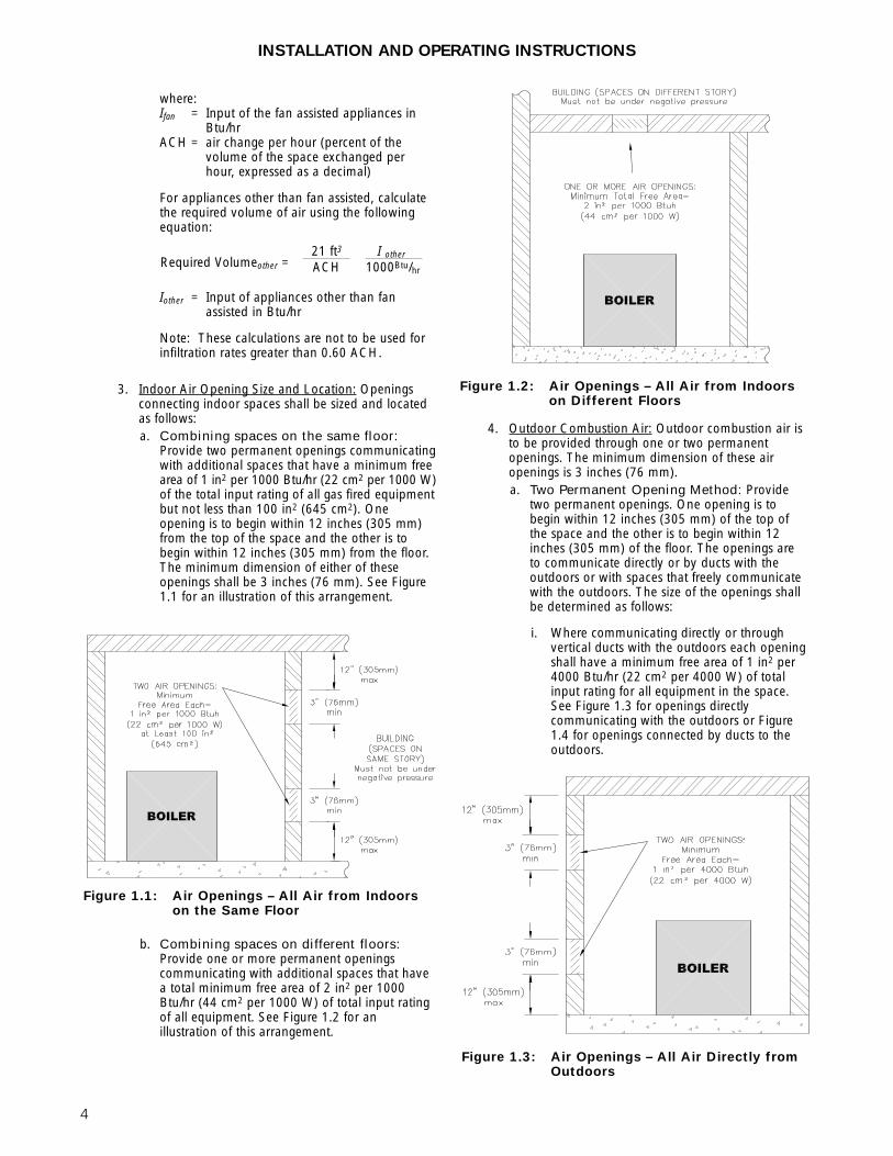
3. Indoor Air Opening Size and Location: Openingsconnecting indoor spaces shall be sized and locatedas follows:a. Combining spaces on the same floor:
Provide two permanent openings communicatingwith additional spaces that have a minimum freearea of 1 in2 per 1000 Btu/hr (22 cm2 per 1000 W)of the total input rating of all gas fired equipmentbut not less than 100 in2 (645 cm2). Oneopening is to begin within 12 inches (305 mm)from the top of the space and the other is tobegin within 12 inches (305 mm) from the floor.The minimum dimension of either of theseopenings shall be 3 inches (76 mm). See Figure1.1 for an illustration of this arrangement.
b. Combining spaces on different floors:Provide one or more permanent openingscommunicating with additional spaces that havea total minimum free area of 2 in2 per 1000Btu/hr (44 cm2 per 1000 W) of total input ratingof all equipment. See Figure 1.2 for anillustration of this arrangement.
4. Outdoor Combustion Air: Outdoor combustion air isto be provided through one or two permanentopenings. The minimum dimension of these airopenings is 3 inches (76 mm).a. Two Permanent Opening Method: Provide
two permanent openings. One opening is tobegin within 12 inches (305 mm) of the top ofthe space and the other is to begin within 12inches (305 mm) of the floor. The openings areto communicate directly or by ducts with theoutdoors or with spaces that freely communicatewith the outdoors. The size of the openings shallbe determined as follows:
i. Where communicating directly or throughvertical ducts with the outdoors each openingshall have a minimum free area of 1 in2 per4000 Btu/hr (22 cm2 per 4000 W) of totalinput rating for all equipment in the space.See Figure 1.3 for openings directlycommunicating with the outdoors or Figure1.4 for openings connected by ducts to theoutdoors.
INSTALLATION AND OPERATING INSTRUCTIONS
Figure 1.1: Air Openings – All Air from Indoorson the Same Floor
Figure 1.2: Air Openings – All Air from Indoorson Different Floors
21 ft3 I other
ACH 1000Btu/hrRequired Volumeother =
Figure 1.3: Air Openings – All Air Directly fromOutdoors
5
ii. Where communicating with the outdoorsthrough horizontal ducts, each opening shallhave a minimum free area of 1 in2 per 2000Btu/hr (22 cm2 per 2000 W) of total ratedinput for all appliances in the space. SeeFigure 1.5.
b. One Permanent Opening Method: Provideone permanent opening beginning within 12inches (305 mm) of the top of the space. Theopening shall communicate directly with theoutdoors, communicate through a vertical orhorizontal duct, or communicate with a spacethat freely communicates with the outdoors. Theopenings shall have a minimum free area of 1 in2
per 3000 Btu/hr of total rated input for allappliances in the space and not less than thesum of the cross-sectional areas of all ventconnectors in the space. The gas fired equipmentshall have clearances of at least 1 inch (25 mm)from the sides and back and 6 inches (150 mm)from the front of the appliance. See Figure 1.6for this arrangement.
5. Combination Indoor and Outdoor Combustion Air:If the required volume of indoor air exceeds theavailable indoor air volume, outdoor air openings orducts may be used to supplement the availableindoor air provided:a. The size and location of the indoor openings
comply with Subsection 3.
b. The outdoor openings are to be located inaccordance with Subsection 4.
c. The size of the outdoor openings are to be sizedas follows:
where:Areq = minimum area of outdoor openings.Afull = full size of outdoor openings calculated
in accordance with Subsection 4.Vavail = available indoor air volumeVreq = required indoor air volume
6. Engineered Installations: Engineered combustion airinstallations shall provide an adequate supply ofcombustion, ventilation, and dilution air and shall beapproved by the authority having jurisdiction.
7. Mechanical Combustion Air Supply:
a. In installations where all combustion air isprovided by a mechanical air supply system, thecombustion air shall be supplied from theoutdoors at the minimum rate of 0.35 ft3/min per1000 Btu/hr (0.034 m3/min per 1000 W) of thetotal rated input of all appliances in the space.
b. In installations where exhaust fans are installed,additional air shall be provided to replace theexhaust air.
Vavail1 –Vreq
Areq = Afull x
Figure 1.5: Air Openings – All Air from Outdoorsthrough Horizontal Ducts
Figure 1.6: Air Openings – All Air from Outdoorsthrough One Opening
Figure 1.4: Air Openings – All Air from Outdoorsthrough Vertical Ducts
INSTALLATION AND OPERATING INSTRUCTIONS
6
c. Each of the appliances served shall beinterlocked to the mechanical air supply toprevent main burner operation where themechanical air supply system is not in operation.
d. In buildings where the combustion air is providedby the mechanical ventilation system, the systemshall provide the specified combustion air rate inaddition to the required ventilation air.
8. Louvers & Grills:a. The required size of openings for combustion,
ventilation, and dilution air shall be based on thenet free area of each opening.
i. Where the free area through a louver or grilleis known, it shall be used in calculating theopening size required to provide the free areaspecified.
ii. Where the free area through a louver or grilleis not known, it shall be assumed that woodenlouvers will have 25% free area and metallouvers and grilles will have 75% free area.
iii. Nonmotorized dampers shall be fixed in theopen position.
b. Motorized dampers shall be interlocked with theequipment so that they are proven in the fullopen position prior to ignition and duringoperation of the main burner.
i. The interlock shall prevent the main burnerfrom igniting if the damper fails to openduring burner startup.
ii. The interlock shall shut down the burner ifthe damper closes during burner operation.
9. Combustion Air Ducts:a. Ducts shall be constructed of galvanized steel or
an equivalent corrosion- resistant material.
b. Ducts shall terminate in an unobstructed space,allowing free movement of combustion air to theappliances.
c. Ducts shall serve a single space.
d. Ducts shall not serve both upper and lowercombustion air openings where both suchopenings are used. The separation between ductsserving upper and lower combustion airopenings shall be maintained to the source ofcombustion air.
e. Ducts shall not be screened where terminating inan attic space.
f. Horizontal upper combustion air ducts shall notslope downward toward the source of thecombustion air.
g. The remaining space surrounding a chimneyliner, gas vent, special gas vent, or plastic pipinginstalled within a masonry, metal, or factory builtchimney shall not be used to supply combustionair.
h. Combustion air intake openings located on theexterior of buildings shall have the lowest side ofthe combustion air intake opening at least 12inches (305 mm) above grade.
D. PLANNING THE LAYOUTPrepare sketches and notes of the layout to minimize thepossibility of interferences with new or existingequipment, piping, venting and wiring.
E. MASSACHUSETTS INSTALLATIONS
Massachusetts requires manufacturers of Side WallVented boilers to provide the following informationfrom the Massachusetts code:
• A hard wired carbon monoxide detector with analarm and battery back-up must be installed onthe floor level where the gas equipment is to beinstalled AND on each additional level of thedwelling, building or structure served by the sidewall horizontal vented gas fueled equipment.
• In the event that the side wall horizontally ventedgas fueled equipment is installed in a crawl spaceor an attic, the hard wired carbon monoxidedetector with alarm and battery back-up may beinstalled on the next adjacent floor level.
• Detector(s) must be installed by qualified licensedprofessionals.
• APPROVED CARBON MONOXIDEDETECTORS: Each carbon monoxide detectorshall comply with NFPA 720 and be ANSI/UL2034 listed and IAS certified.
• SIGNAGE: A metal or plastic identification plateshall be permanently mounted to the exterior ofthe building at a minimum height of eight (8) feetabove grade directly in line with the exhaust ventterminal for the horizontally vented gas fueledheating appliance or equipment. The sign shallread, in print size no less than one-half (1/2) inchin size, “GAS VENT DIRECTLY BELOW.KEEP CLEAR OF ALL OBSTRUCTIONS”.
Liquefied Petroleum (LP) is heavier than air and maycollect or “pool” in a low area in the event of a leakfrom defective equipment. This gas may then ignite,resulting in a fire or explosion.
WARNING
INSTALLATION AND OPERATING INSTRUCTIONS
7
• EXEMPTIONS to the requirements listed above:
° The above requirements do not apply if theexhaust vent termination is seven (7) feet ormore above finished grade in the area of theventing, including but not limited to decksand porches.
° The above requirements do not apply to aboiler installed in a room or structure separatefrom the dwelling, building or structure usedin whole or in part for residential purposes.See the latest edition of Massachusetts Code248 CMR for complete verbage and also foradditional (non-vent related) requirements(248 CMR is available online).
If your installation is NOT in Massachusetts, pleasesee your authority of jurisdiction for requirementsthat may be in effect in your area. In the absence ofsuch requirements, follow the National Fuel GasCode, ANSI Z223.1/NFPA 54 and/or CAN/CSAB149.1, Natural Gas and Propane Installation Code.
Venting System Installation Instructions – Seeboiler manual and instructions provided with theVenting System components. Additional copies maybe obtained from the Venting System Manufacturerby visiting the following web addresses:
1. Provide a sound, level foundation. Locate boiler asnear to the chimney or outside wall as possible andcentralized with respect to the heating system.
2. Locate boiler in front of installation position before removing crate.
3. If using combustible floor pan, position pan onfoundation or flooring.
4. Separate the wood shipping pallet from the boilerbase by removing two (2) hold-down bolts at eachend of the boiler base.
5. Move boiler into final position. If using combustiblefloor pan, install boiler on pan as outlined in theinstructions included with the pan.
2. BOILER SET-UP
8
A. BOILER SUPPLY AND RETURN
1. Size the supply and return to suit the system. Atypical piping arrangement is shown in Figure 3.1.Refer also to the I=B=R Guide to ResidentialHydronic Heating Installation/Design for additionalguidance during water piping installation.
2. Return Piping:a. Pipe the outlet connection of the circulator to a
tee, provided with a drain valve, at the 1-1/4NPT return tapping near the bottom of the leftsection. Pipe the return to the inlet connection ofthe circulator.
3. Supply Piping:Pipe the supply to the 1-1/2 NPT supply tapping atthe top of the boiler.
4. When system return water temperature will be below130°F (54°C), pipe the boiler with a bypassarrangement to blend the system return and hotsupply to obtain at least 130°F (54°C) entering theboiler.
5. If desired, install the circulator in the alternatelocation shown in Figure 3.1.
3. WATER PIPING AND CONTROLS
Figure 3.1: Supply and Return Piping
INSTALLATION AND OPERATING INSTRUCTIONS
9
6. Install this boiler so that the gas ignition systemcomponents are protected from water (dripping,spraying, etc.) during appliance operation andservice (circulator replacement, condensate trap,control replacements, etc.).
7. If this boiler and distribution system is used inconjunction with a refrigeration system, pipe thechilled medium in parallel with the boiler and installthe proper valve to prevent the chilled medium fromentering the boiler. A drawing illustrating this hook-up is provided in Figure 3.2.
8. When the boiler is connected to heating coils locatedin air handling units where they may be exposed torefrigerated air circulation, install flow control valvesor other automatic means to prevent gravitycirculation of the boiler water during the coolingcycle.
9. If this boiler is installed above radiation level,provide a low water cutoff device, either as a part ofthe boiler or at the time of boiler installation.
B. SAFETY RELIEF VALVE
1. Locate safety relief valve and fittings in bagassembly.
2. If air elimination is not required at the safety reliefvalve tapping, install valve and piping as shown inFigure 3.3.
3. For air elimination at the safety relief valve tapping,install valve and piping as shown in Figure 3.4.
Pipe the discharge of safety relief valve to preventinjury in the event of pressure relief. Pipe thedischarge to a drain. Provide piping that is the samesize as the safety relief valve outlet.
Figure 3.3: Safety Relief Valve Hook-UpInstallation with Air Elimination in System Piping
Figure 3.2: Parallel Hook-up with Water Chiller
INSTALLATION AND OPERATING INSTRUCTIONS
10
C. PIPING FOR ZONED SYSTEMS
1. See Figures 3.5 and 3.6 for basic zoned systemlayouts.
2. Run each zone pipe down then up to zone toprevent air accumulation in piping.
3. If required, provide means to isolate and drain eachzone separately.
Figure 3.5: Zone Piping with Zone Valves
Figure 3.6: Zone Piping with Circulators
INSTALLATION AND OPERATING INSTRUCTIONS
11
D. EXPANSION TANK
1. Consult the tank manufacturer’s instructions forspecific information relating to tank installation. Sizethe expansion tank for the required system volumeand capacity. See Table 10.2 in Section 10 for boilerwater capacity.
2. Expansion tanks are available with built-in fill valvesand check valves for reducing supply water pressureand maintaining minimum system pressure. Checkthe design features of the tank and provide valves asnecessary.
Refer back to Figure 3.1 for typical expansion tank piping.
E. INDIRECT-FIRED WATER HEATERIf the boiler is to be used in conjunction with an indirect-fired water heater, refer to Figure 3.7 for typical piping.Follow the instructions provided by the water heatermanufacturer. Pipe the water heater as a separate zone.
F. FREEZE PROTECTIONFor new or existing systems that must be freeze-protected:
1. Glycol in hydronic applications is speciallyformulated for this purpose. It includes inhibitorswhich prevent the glycol from attacking metallicsystem components. Make certain that the systemfluid is checked for the correct glycol concentrationand inhibitor level.
2. The antifreeze solution should be tested at least oncea year and as recommended by the antifreezemanufacturer.
3. Antifreeze solutions expand more than water. Forexample, a 50% by volume solution expands 4.8%in volume for a temperature increase from 32°F(0°C) to 180°F (82°C), while water expands 3% withthe same temperature rise. Allowance must be madefor this expansion in system design.
Figure 3.7: Typical Piping with Indirect-Fired Water Heater
INSTALLATION AND OPERATING INSTRUCTIONS
Use only inhibited propylene glycol solutions of up to50% by volume with water. Ethylene glycol is toxicand can attack gaskets and seals used in hydronicsystems.
WARNING
12
A. GENERAL
1. Install vent system in accordance with the "Venting ofEquipment" Chapter of the National Fuel Gas Code,ANSI Z223.1/NFPA 54, the "Venting Systems and AirSupply for Appliances" Section of the CAN/CSAB149.1, Natural Gas and Propane Installation Code.or applicable provisions of the local building codes.
2. Do not connect vent connectors serving appliancesvented by natural draft into any portion ofmechanical draft systems operating under positivepressure.
3. Refer to the following venting options to determinewhich method is applicable.ON –
B. CHIMNEY VENTING
If venting into a masonry chimney; chimney must belined with a fire clay tile liner or corrosion resistant metalliner. Type B vent may also be used as a lining system oras a stand alone chimney vent.
1. The vent system, when installed per the followinginstructions, will operate with a negative pressure (draft).
2. Horizontal portions of the venting system shall slopeupward at least 1/4″ per lineal foot (21 mm permeter) between boiler and chimney. The vent pipeshall be supported to prevent sagging; using metalstrapping or equivalent means at no more than 4 ft.(1.2 meter) intervals.
3. Locate fan adapter, silicone, hardware and fanadapter gasket in boiler miscellaneous parts box and attach to blower outlet flange. Refer to Fig. 4.1for details.
4. Apply 1/4″ (6 mm) bead of silicone around fanadapter and slip increaser over the fan adapter. Referto Table 4.1 for increaser and chimney sizes.Increaser to be provided by installer.
5. Single wall vent pipe should be furnished betweenincreaser and chimney. If the vent connector shall belocated in or pass through a cold area, the ventconnector shall be type B material.
C. DIRECT EXHAUST; HORIZONTALVENTING
1. This vent system will operate with a positive pressurein the vent pipe. Follow vent pipe manufacturersinstructions for proper assembly of vent pipe andfittings.
4. VENTING
Figure 4.1: Chimney Venting
INSTALLATION AND OPERATING INSTRUCTIONS
Table 4.1: Increaser & Chimney Size
BoilerSize Increaser Size Vent Size
DiameterChimney Height
70105140165
3" to 4" (7.6 to 10.2 cm)3" to 5" (7.6 to 12.7 cm)3" to 5" (7.6 to 12.7 cm)3" to 5" (7.6 to 12.7 cm)
4" (10.2 cm)5" (12.7 cm)5" (12.7 cm)5" (12.7 cm)
15' (4.5 m)15' (4.5 m)15' (4.5 m)15' (4.5 m)
All joints of positive pressure vent systems must besealed completely to prevent leakage of flue productsinto the living space.
WARNING
Flue gases will condense as they exit the venttermination. This condensate can freeze on exteriorbuilding surfaces which may cause discoloration ofthese surfaces.
NOTICE
13
2. Refer to Table 4.2 for minimum and maximum ventlength allowed.
3. Maintain a minimum 2″ (51 mm) clearance betweenvent pipe and combustible construction.
4. When installing vent pipe through a combustiblewall, pipe must pass through a metal wall thimble;maintain a 2″ (51 mm) clearance between vent pipeand thimble. Follow thimble manufacturer’sinstructions. Seal between thimble and exterior wallusing exterior-rated caulk or silicone to prevent waterdamage and also to prevent recirculation of flueproducts into the structure.
5. Determine vent terminal location.a. Vent terminal shall be located at least 3 feet (1
meter) above any forced air inlet located within10 feet (3 meters).
b. Vent terminal shall be located at least 4 feet (1.2meters) below, 4 feet (1.2 meters) horizontallyfrom, or 1 foot (0.3 meters) above any door,window, or gravity air inlet into any building.
c. Vent terminal shall be located at least 1 foot (0.3meters) above ground level or normal snow lines.See subsection 7 below if terminal needs to beextended above ground level or snow line.
d. Vent terminal shall not be located over publicwalkways where condensate could create anuisance or hazard.
e. When adjacent to a public walkway, ventterminal shall be at least 7 feet (2.1 meters)above grade.
f. Vent terminal shall be located at least 4 feet (1.2meters) horizontally from electric meters, gasmeters, regulators and relief equipment. InCanada, this dimension must be 6 feet (2 meters).
g. Vent terminal should not be located directlyunder roof overhangs to prevent icicles fromforming.
6. Vent Pipe Assembly:a. Horizontal portions of the vent pipe shall slope
down not less than 1/4″ per foot (21 mm permeter) from the boiler to the vent terminationelbow. If this horizontal run is pitched towardboiler, provide a horizontal drain tee as perinstructions in section D. Direct Exhaust;Vertical Venting.
b. Secure vent pipe using metal strapping, clampsand/or other means. Do not screw into the ventpipe.
• Horizontal portions of the vent pipe must besupported at intervals no greater than fourfeet to prevent sagging/separation.
• Secure vent pipe to the thimble/wall toprevent possible movement from incidentalcontact on the vent terminal.
c. Type vent material approved is AL29-4C, 3 inch(76 mm) diameter stainless steel; manufacturedby Heat-Fab® (Saf-T-Vent); Z-Flex® (Z-Vent);ProTech (FasNSeal™); Flex-L (StaR-34); Metal-Fab (Corr/Guard).
d. Attach the fan adapter to blower outlet flangeusing gasket and 1/4″ (6 mm) -20 nuts andwashers, (parts located in miscellaneous partsbox).
e. Refer to Figure 4.3 that lists special vent adaptersfor connection to boiler fan adapter. Thesespecial adapters are not supplied with boiler.
f. Attach vent pipe adapter to boiler fan adapter byapplying a 1/4″ (6 mm) bead of hightemperature silicone around diameter of fanadapter and slip vent pipe adapter over the fanadapter. Fill in any voids with silicone andsmooth out with moistened finger or flat tool.
g. If using Z-Flex® pipe, slide vent pipe over the first 2-1/2″ (64 mm) of the fan adapter and securejoint connection with the Z-Flex® looking bandsmaking sure that locking band has contact withfan adapter at boiler end and vent pipe.
h. Attach remaining pipe and fittings permanufacturer’s vent instructions. Use only thesilicone recommended by the vent pipemanufacturer.
i. The only approved vent termination is a 3″ (76mm) 90° elbow. Refer to Figure 4.4. Vent pipemust be sealed to the thimble (or outside wall if-non-combustible construction) using silicone toprevent recirculation of flue products into thestructure.
*Maximum Vent Length to be reduced by 5 feet (1.5meters) for each 90° elbow added that ismanufactured by Z-Flex®, Heat-Fab® and Protech.
*Maximum Vent Length to be reduced by 7-1/2 feet(2.3 meters) for each 90° elbow added that ismanufactured by Flex-L.
The outside vent terminal (90° Elbow) is notincluded in Equivalent Vent Length.
7. Refer to Figure 4.2 for vertical offset option. Themaximum offset is 5 feet. With the exception of thelast 90° elbow which serves as the vent terminal, theadditional elbows and straight vent pipe must beconsidered when determining maximum vent length.Provide a horizontal drain tee as described inSection D. Direct Exhaust; Vertical Venting.
*Equivalent Length of 3″ diameterStainless Steel Vent Pipe
Minimum Vent Length Maximum Vent Length
14
INSTALLATION AND OPERATING INSTRUCTIONS
Figure 4.2: Direct Exhaust, Sidewall Venting with Vertical Off-Set
Figure 4.3: Vent Pipe Adapters
15
D. DIRECT EXHAUST; VERTICAL VENTING
1. This vent system will operate with a positive pressurein the vent pipe. Follow vent pipe manufacturer’sinstructions for proper assembly of vent pipe andfittings.
2. Refer to Table 4.2 for minimum and maximum ventlength allowed.
3. Maintain a minimum 2″ (51 mm) clearance betweenvent pipe and combustible construction.
4. Follow instructions under section C. DIRECTEXHAUST; HORIZONTAL VENTING items 6bthrough 6h.
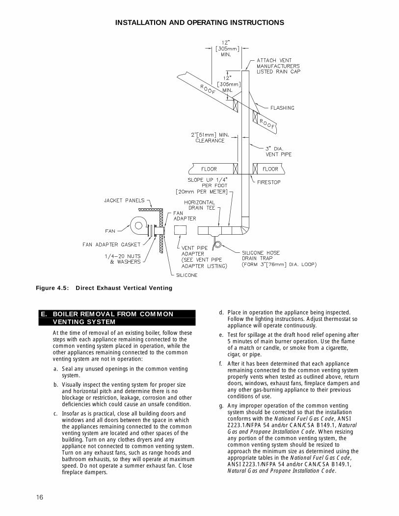
5. Horizontal portions of the vent pipe shall slope upnot less than 1/4″ per foot (21 mm per meter) fromthe boiler to the vertical vent.
6. Provide a horizontal drain tee in the horizontal ventrun. Use silicone drain hose with a 3″ (76 mm)diameter loop trap with a water seal. Pipe to drainper local codes.
7. Refer to vent pipe manufacturer’s instructions undervertical venting section for recommendation forpenetration through floors and roofs.
8. Vent must terminate 12″ (305 mm) above expectedsnow lines.
9. See Figure 4.5 for details.
INSTALLATION AND OPERATING INSTRUCTIONS
Figure 4.4: Direct Exhaust; Sidewall Venting
16
INSTALLATION AND OPERATING INSTRUCTIONS
E. BOILER REMOVAL FROM COMMONVENTING SYSTEM
At the time of removal of an existing boiler, follow thesesteps with each appliance remaining connected to thecommon venting system placed in operation, while theother appliances remaining connected to the commonventing system are not in operation:
a. Seal any unused openings in the common ventingsystem.
b. Visually inspect the venting system for proper sizeand horizontal pitch and determine there is noblockage or restriction, leakage, corrosion and otherdeficiencies which could cause an unsafe condition.
c. Insofar as is practical, close all building doors andwindows and all doors between the space in whichthe appliances remaining connected to the commonventing system are located and other spaces of thebuilding. Turn on any clothes dryers and anyappliance not connected to common venting system.Turn on any exhaust fans, such as range hoods andbathroom exhausts, so they will operate at maximumspeed. Do not operate a summer exhaust fan. Closefireplace dampers.
d. Place in operation the appliance being inspected.Follow the lighting instructions. Adjust thermostat soappliance will operate continuously.
e. Test for spillage at the draft hood relief opening after5 minutes of main burner operation. Use the flameof a match or candle, or smoke from a cigarette,cigar, or pipe.
f. After it has been determined that each applianceremaining connected to the common venting systemproperly vents when tested as outlined above, returndoors, windows, exhaust fans, fireplace dampers andany other gas-burning appliance to their previousconditions of use.
g. Any improper operation of the common ventingsystem should be corrected so that the installationconforms with the National Fuel Gas Code, ANSIZ223.1/NFPA 54 and/or CAN/CSA B149.1, NaturalGas and Propane Installation Code. When resizingany portion of the common venting system, thecommon venting system should be resized toapproach the minimum size as determined using theappropriate tables in the National Fuel Gas Code,ANSI Z223.1/NFPA 54 and/or CAN/CSA B149.1,Natural Gas and Propane Installation Code.
Figure 4.5: Direct Exhaust Vertical Venting
17
1. Size and install the gas supply piping properly inorder to provide a supply of gas sufficient to meetthe maximum demand without undue loss ofpressure between the meter and the boiler.
2. Determine the volume of gas to be provided to theboiler in cubic feet per hour. To obtain this value,divide the Btu per hour rating (on the boiler ratingplate) by the heating value of the gas in Btu percubic feet. Obtain the heating value of the gas fromthe gas supplier. As an alternative, use Table 5.1 or5.2 on the next page to obtain the volume of gas tobe provided to the boiler.
3. Use the value obtained above as the basis for pipingsizing. Size the gas piping in accordance with Table5.3. Consult the National Fuel Gas Code ANSIZ223.1/NFPA 54 and or CAN/CSA B149.1, NaturalGas and Propane Installation Code for proper sizingoptions.
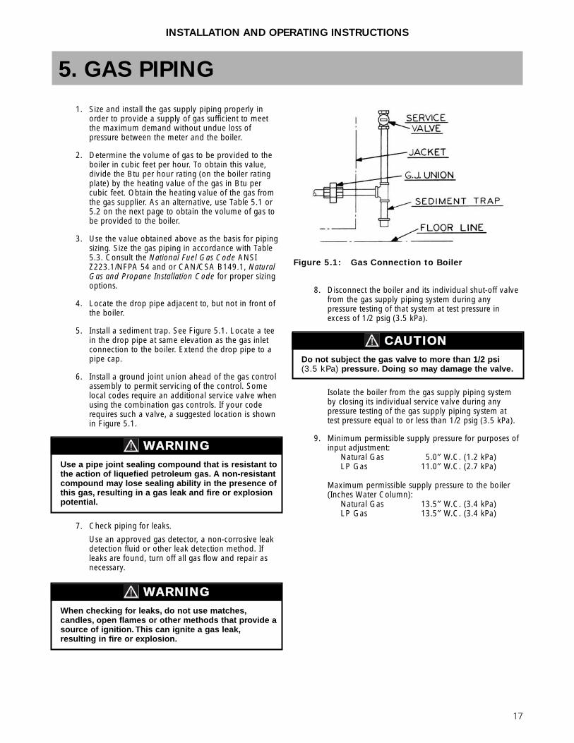
4. Locate the drop pipe adjacent to, but not in front ofthe boiler.
5. Install a sediment trap. See Figure 5.1. Locate a teein the drop pipe at same elevation as the gas inletconnection to the boiler. Extend the drop pipe to apipe cap.
6. Install a ground joint union ahead of the gas controlassembly to permit servicing of the control. Somelocal codes require an additional service valve whenusing the combination gas controls. If your coderequires such a valve, a suggested location is shownin Figure 5.1.
7. Check piping for leaks.
Use an approved gas detector, a non-corrosive leakdetection fluid or other leak detection method. Ifleaks are found, turn off all gas flow and repair asnecessary.
8. Disconnect the boiler and its individual shut-off valvefrom the gas supply piping system during anypressure testing of that system at test pressure inexcess of 1/2 psig (3.5 kPa).
Isolate the boiler from the gas supply piping systemby closing its individual service valve during anypressure testing of the gas supply piping system attest pressure equal to or less than 1/2 psig (3.5 kPa).
9. Minimum permissible supply pressure for purposes ofinput adjustment:
Natural Gas 5.0″ W.C. (1.2 kPa)LP Gas 11.0″ W.C. (2.7 kPa)
Maximum permissible supply pressure to the boiler(Inches Water Column):
Natural Gas 13.5″ W.C. (3.4 kPa)LP Gas 13.5″ W.C. (3.4 kPa)
5. GAS PIPING
Figure 5.1: Gas Connection to Boiler
When checking for leaks, do not use matches,candles, open flames or other methods that provide asource of ignition. This can ignite a gas leak,resulting in fire or explosion.
WARNING
Use a pipe joint sealing compound that is resistant tothe action of liquefied petroleum gas. A non-resistantcompound may lose sealing ability in the presence ofthis gas, resulting in a gas leak and fire or explosionpotential.
WARNING
Do not subject the gas valve to more than 1/2 psi (3.5 kPa) pressure. Doing so may damage the valve.
CAUTION
INSTALLATION AND OPERATING INSTRUCTIONS
18
Table 5.3: Pipe CapacityCapacity of pipe of different diameters and lengths in cubic feet per hour[cubic meter per hour] with a pressure drop of 0.3 inches of water [75 kPa]and a specific gravity of 0.60. No allowance for an ordinary number of fittings is required.
Maximum Capacity Correction Factors forSpecific Gravity other than 0.60.
19
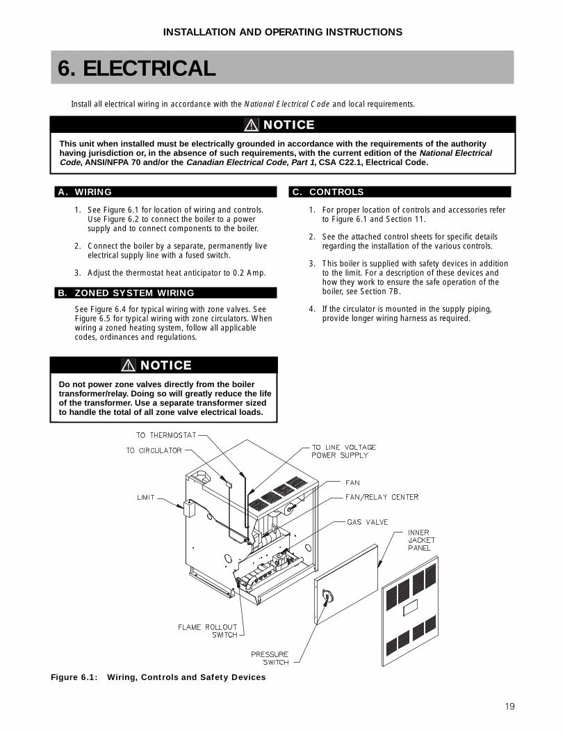
A. WIRING
1. See Figure 6.1 for location of wiring and controls.Use Figure 6.2 to connect the boiler to a powersupply and to connect components to the boiler.
2. Connect the boiler by a separate, permanently liveelectrical supply line with a fused switch.
3. Adjust the thermostat heat anticipator to 0.2 Amp.
B. ZONED SYSTEM WIRING
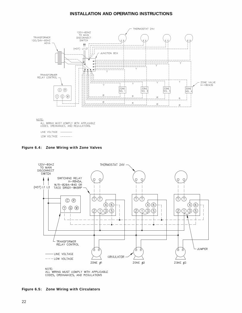
See Figure 6.4 for typical wiring with zone valves. SeeFigure 6.5 for typical wiring with zone circulators. Whenwiring a zoned heating system, follow all applicablecodes, ordinances and regulations.
C. CONTROLS
1. For proper location of controls and accessories referto Figure 6.1 and Section 11.
2. See the attached control sheets for specific detailsregarding the installation of the various controls.
3. This boiler is supplied with safety devices in additionto the limit. For a description of these devices andhow they work to ensure the safe operation of theboiler, see Section 7B.
4. If the circulator is mounted in the supply piping,provide longer wiring harness as required.
INSTALLATION AND OPERATING INSTRUCTIONS
6. ELECTRICAL
This unit when installed must be electrically grounded in accordance with the requirements of the authorityhaving jurisdiction or, in the absence of such requirements, with the current edition of the National ElectricalCode, ANSI/NFPA 70 and/or the Canadian Electrical Code, Part 1, CSA C22.1, Electrical Code.
NOTICE
Figure 6.1: Wiring, Controls and Safety Devices
Install all electrical wiring in accordance with the National Electrical Code and local requirements.
Do not power zone valves directly from the boilertransformer/relay. Doing so will greatly reduce the lifeof the transformer. Use a separate transformer sizedto handle the total of all zone valve electrical loads.
NOTICE
20
D. SEQUENCE OF OPERATION
1. Thermostat calls for heat, energizes Control Relay(CR).
2. Control Relay (CR) energizes circulator.
3. Limit senses boiler water temperature. Preventsboiler operation until water temperature fallsapproximately 15°F (8°C) below the cut-outtemperature.
4. Limit energizes Fan and Isolation Relay (IR).
5. Negative pressure induced by fan switches PressureSwitch, continuing power through closed contacts(IR-1) and flame roll-out switch.
6. Gas valve energizes.a. Igniter on.
b. Pilot gas on, igniting pilot.
7. Pilot flame detected.a. Igniter off.
b. Main gas on, igniting main burners.
Note: If pilot flame is not detected within 30 seconds,the igniter is turned off for 30 seconds, and then turnedback on. If the pilot is not detected within 30 seconds,the igniter and pilot gas are turned off for 5 minutes.The sequence then resumes at Step 6a.
8. Call for heat ends.a. Pilot and main gas off, extinguishing pilot and
main burners.
b. Fan and circulator off.
Figure 6.2: Wiring and Connection Diagram
INSTALLATION AND OPERATING INSTRUCTIONS
21
Figure 6.3: Ignition System Operating Sequence
INSTALLATION AND OPERATING INSTRUCTIONS
22
INSTALLATION AND OPERATING INSTRUCTIONS
Figure 6.4: Zone Wiring with Zone Valves
Figure 6.5: Zone Wiring with Circulators
23
A. COMPLETING THE INSTALLATION
1. Confirm that all water, gas and electricity areturned off.
2. Inspect the boiler combustion chamber for foreignobjects and remove if present.
3. Check physical condition of burners and pilot. Makecertain that there are no unusual bends orperforations in the burners or pilot. Replacecomponents if necessary.
4. Verify that water piping, venting, gas piping andelectrical wiring and components are installedproperly. Refer back to previous sections of theseinstructions as well as equipment manufacturer’sinstructions as necessary.
5. Fill the boiler and system with water, making certainto vent all air from all points in the system. To checkwater level in the system, open and close each ventin the system. Water should exit from each ventwhen it is opened.
6. The pressure reducing valve on the fill line willtypically allow the system to be filled and pressurizedto 12 psi. (83 kPa). Consult the valve and expansiontank manufacturer for more specific information.
7. Check joints and fittings throughout the system forleaks. If leaks are found, drain the system and repairas required.
8. Connect a manometer to the gas valve inlet pressuretap. See Figure 7.2.
9. Confirm that the gas supply pressure to the boiler isabove the minimum and below the maximum valuesfor the gas being used. See the end of Section 5 forthese values. If a supply pressure check is required,isolate the boiler and gas valve before performingthe pressure check. If the supply pressure is too highor too low, contact the gas supplier.
10. Turn on electricity and gas to boiler.
11. Light the boiler by following the Lighting/OperatingInstructions label mounted to the jacket panel. Theinitial ignition may require several tries as the pipingis purged of air.
12. Use the sequence descriptions in Figures 6.2 and 6.3in Section 6 (Electrical) to follow light-off andshutdown sequences and to assist in diagnosingproblems. If the boiler does not function properly,consult Section 8, Troubleshooting.
13. The gas manifold and control assembly are made ofgas-tight, completely factory assembled and installedcomponents of the base assembly. See Figure 7.1and 7.2.
INSTALLATION AND OPERATING INSTRUCTIONS
7. START-UP PROCEDURES
Figure 7.1: Gas Valve, Manifoldand Burner Assembly – Intermittent Ignition
Figure 7.2: Valve Tapping and Adjustment Screw Locations
24
INSTALLATION AND OPERATING INSTRUCTIONS
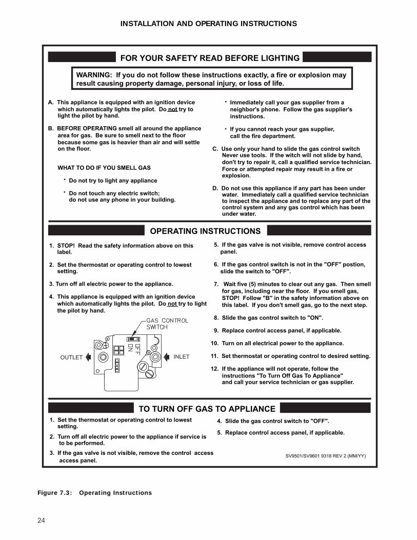
Figure 7.3: Operating Instructions
SV9501/SV9601 9318 REV 2 (MM/YY)
FOR YOUR SAFETY READ BEFORE LIGHTING
WARNING: If you do not follow these instructions exactly, a fire or explosion may result causing property damage, personal injury, or loss of life.
OPERATING INSTRUCTIONS
TO TURN OFF GAS TO APPLIANCE1. Set the thermostat or operating control to lowest setting.
2. Turn off all electric power to the appliance if service is to be performed.3. If the gas valve is not visible, remove the control access access panel.
4. Slide the gas control switch to "OFF".
5. Replace control access panel, if applicable.
1. STOP! Read the safety information above on this label.
2. Set the thermostat or operating control to lowest setting.
3. Turn off all electric power to the appliance.
4. This appliance is equipped with an ignition device which automatically lights the pilot. Do not try to light the pilot by hand.
5. If the gas valve is not visible, remove control access panel. 6. If the gas control switch is not in the "OFF" postion, slide the switch to "OFF".
7. Wait five (5) minutes to clear out any gas. Then smell for gas, including near the floor. If you smell gas, STOP! Follow "B" in the safety information above on this label. If you don't smell gas, go to the next step.
8. Slide the gas control switch to "ON".
9. Replace control access panel, if applicable.
10. Turn on all electrical power to the appliance.
11. Set thermostat or operating control to desired setting. 12. If the appliance will not operate, follow the instructions "To Turn Off Gas To Appliance" and call your service technician or gas supplier.
A. This appliance is equipped with an ignition device which automatically lights the pilot. Do not try to light the pilot by hand.
B. BEFORE OPERATING smell all around the appliance area for gas. Be sure to smell next to the floor because some gas is heavier than air and will settle on the floor.
WHAT TO DO IF YOU SMELL GAS
Do not try to light any appliance Do not touch any electric switch; do not use any phone in your building.
Immediately call your gas supplier from a neighbor's phone. Follow the gas supplier's instructions.
If you cannot reach your gas supplier, call the fire department.
C. Use only your hand to slide the gas control switch Never use tools. If the witch will not slide by hand, don't try to repair it, call a qualified service technician. Force or attempted repair may result in a fire or explosion.
D. Do not use this appliance if any part has been under water. Immediately call a qualified service technician to inspect the appliance and to replace any part of the control system and any gas control which has been under water.
25
B. CONTROL DESCRIPTIONSSee Figure 6.1 in Section 6 (Electrical) for locations ofthese devices.
1. FLAME ROLL-OUT SAFETY SHUT-OFF SWITCH(FLAME ROLL-OUT SWITCH) – A thermallyactivated switch located between the first burnerfrom the left and the manifold bracket. The flameroll-out safety shut-off switch will sense excessivetemperature caused by continued flame roll-out andshut down main burner gas. This is a non-recyclingswitch that must be replaced once it has beenactivated and the cause of the roll-out eliminated.
2. PRESSURE SWITCH – A pressure sensing devicethat is located in the jacket vestibule. This controlsenses a suction pressure when fan is energized on acall for heat. Switch contacts close allowing controlcircuit to energize ignition system.
3. LIMIT (AQUASTAT) – A thermally activated,manually adjustable switch located on the left side ofthe boiler, towards the top and rear. The temperaturesensing element is placed in the supply and will shutdown main burner gas if the supply water exceedsthe preset temperature limit. This is a recycling switchthat will automatically reset when the supply waterfalls below the preset temperature.
4. LOW WATER CUT-OFF (FOR GRAVITY SYSTEMSOR HOT WATER BOILERS INSTALLED ABOVERADIATION LEVEL) – A level-sensing device (floator probe) located in supply piping near the boiler. Ifwater level in the system drops below the control’sposition, it will shut down main burner gas. Thecontrol will automatically reset once the water levelrises above its position.
C. ADJUSTMENT OF GAS PRESSUREREGULATOR
1. Connect a manometer to 1/8 N.P.T. tapping on gasmanifold, set manifold pressure as follows for variousgases.a. Natural Gas . . . . . . . . . .3.5″ W.C. (0.9 kPa)
b. LP Gas . . . . . . . . . . . . .10.0″ W.C. (2.5 kPa)
2. To adjust gas pressure, turn adjusting screw of gaspressure regulator counterclockwise to decreasepressure, clockwise to increase pressure. Refer toFigure 7.2 for location of gas pressure regulator.Replace the cap screw when adjustment is complete.
3. In no case should the final manifold pressure varymore than ±0.3 inches water column (0.07 kPa)from the above specified pressures. Any necessarymajor changes in the flow should be made bychanging the size of the burner orifice spuds.
4. When adjustment is complete, turn off boiler, gasflow and electricity to boiler. Remove manometerconnection from valve and plug tapping with plugprovided. Turn utilities back on and resumecheckout.
D. CHECKING BURNER INPUT
1. Refer to rating label mounted on the jacket top panelto obtain the rated BTU per hour input. In no caseshall the input to the boiler exceed the value shownon the rating label.
2. Check input by use of the following formula (PB Heat suggests reading meter for 2 Cu.Ft.[0.0566 cubic meter]):
U.S. Customary Units:Input (BTU/Hr.)= 3600 x F x H
TWhere:3600 – Seconds per hour
F – Cubic Feet of Gas Registered on MeterH – Heat Value of Gas in BTU/Cubic FeetT – Time in Seconds the Meter is Read
SI Metric UnitsInput (kW)= 3600 x F x H
T x 3.6Where:3600 – Seconds per hour
3.6 – Megajoule (MJ) per kilowatt hour (kwhr)F – Cubic Meters of Gas Registered on MeterH – Heating Value of Gas in MJ/Cubic MeterT – Time in Seconds the Meter is Read
3. As an alternative, use Table 7.1a and 7.1b. Use theheating value provided by gas supplier. Use astopwatch to record the time it takes for 2 cubic feet(0.0566 cubic meter) of gas to pass through themeter. Read across and down to determine rate.
E. CHECK-OUT PROCEDURE
1. After starting the boiler, be certain all controls areworking properly. Check to be sure that the limit willshut off the boiler in the event of excessive watertemperature. This can be done by lowering the limitsetting until the main burners shut down. Whenproper limit function is confirmed, return the dial toits previous setting.
2. To check operation of the ignition system safetyshut-off features:a. Turn gas supply off.
b. Set thermostat or controller above roomtemperature to call for heat. Watch for igniterglow at pilot burner.
c. Igniter will continue to glow for 30 seconds, de-energize for 30 seconds, then re-energize andglow for another 30 seconds. It will then de-energize for 5 minutes before restarting thesequence.
d. Turn gas supply on.
e. Reset the boiler and control by followingOperating Instructions.
f. Observe boiler operation through one completecycle.
INSTALLATION AND OPERATING INSTRUCTIONS
26
INSTALLATION AND OPERATING INSTRUCTIONS
Table 7.1a: Meter Conversion Natural Gas (U.S. Customary Units)
Table 7.1b: Meter Conversion Natural Gas (SI Metric System)
Burner inputs in kW for various meter timings andheating values. (Tables based on 0.0566 cubic metersof gas through the meter).
Burner inputs in Btu/hr for various meter timings andheating values. (Tables based on 2 cubic feet of gasthrough the meter).
3. Low Water Cut-Off (if used) – Consult themanufacturer’s instructions for the low water cut-offoperational check procedure.
4. Check the system to make sure there are no leaks oroverfilling problems which might cause excessivemake-up water to be added. Make-up water causesliming in the boiler and brings in oxygen. Oxygencan cause severe damage to the boiler throughoxygen corrosion pitting.
5. Check the expansion tank and automatic fill valve (ifused) to confirm that they are operating correctly. Ifeither of these components causes high pressure inthe system, the boiler relief valve will weep or open,allowing fresh water to enter the system.
6. Do not allow the system controls to subject the boilerto excessively low water temperatures, which wouldcause condensation of flue gases and corrosion ofthe boiler. Operate the boiler at a temperature above130°F (55°C). Adjust the boiler limit as required tomaintain boiler temperature above this level.
7. Check the general condition of the system includingpiping support, joints, etc. Check cleanliness of theradiators, baseboard units and/or convectors. Cleanthem to the extent possible. If radiators do not heatevenly, vent any remaining air from them.
8. Review operation and User’s Information Manualwith end-user.
9. Hang the Installation, Operation and MaintenanceManual and User’s Information Manual in anaccessible position near the boiler.
27
A. SHUT-DOWN CAUSED BY PILOT OUTAGE, PRESSURE SWITCH ORFLAME ROLL-OUT SAFETY SHUT-OFF SWITCHIn the event of a shut-down caused by a pilot outage,action of the pressure switch or flame roll-out safetyshut-off switch effecting a shut-down of the mainburners:
a. Refer to the Operating Instructions in Figure 7.3 toproperly turn off the gas to the boiler.
b. Turn off all electric power to the boiler.c. Call a qualified heating service organization or local
gas company and have the cause of the shut-downinvestigated and corrected.
d. Refer to Operating Instructions tore-start boiler.
B. TROUBLESHOOTING GUIDES
Use Table 8.2 to assist in determining causes andproviding corrective actions to boiler problems. Referalso to Figure 8.2 to troubleshoot the IntermittentIgnition System Control. These guides must be usedonly by qualified service technicians. These individualsmust follow all applicable codes and regulations in repairof any boiler problems.
C. MEASURING SUCTION PRESSURE
Refer to Table 8.1 for fan suction pressure required toenergize control circuit. Measure fan suction pressure asshown in Figure 8.1. Note that as boiler operates,suction pressure will decrease. Measure after 15 minutesof boiler operation.
INSTALLATION AND OPERATING INSTRUCTIONS
8. TROUBLESHOOTING
Should overheating occur or the gas supply fail toshut off, do not turn off or disconnect the electricalsupply to the pump. This may aggravate the problemand increase the likelihood of boiler damage. Instead,shut off the gas supply at a location external to theappliance.
CAUTION
Do not use this appliance if any part has been underwater. Improper or dangerous operation may result.Immediately call a qualified service technician toinspect the boiler and to replace any part of thecontrol system and any gas control which has beenunder water.
WARNING
Label all wires prior to disconnection when servicingcontrols. Wiring errors can cause improper anddangerous operation. Verify proper operation afterservicing.
CAUTION
When servicing or replacing items that communicatewith the boiler water, be certain that:
● There is no pressure on the boiler.● The boiler is not hot.● The power is off.
When servicing the gas valve or pilot, be certain that:● The gas is off.● The electricity is off.
1. See Figure 8.2Burners not functioning. 1. See Figure 8.2
1. Defective gas valve.
2. Short circuit.
Burners will not shutdown.
1. Use Figure 8.2 to troubleshoot intermittentignition gas valve. Replace if necessary.
2. Check and correct wiring.
1. Manifold gas pressure too low.2. Improperly sized/drilled orifice spuds.3. Leaking gas valve.4. Burrs on orifice.5. Low supply gas pressure.
Flashback or burningat orifice spuds.
1. Adjust to proper pressure.2. Install correct spuds.3. Replace valve.4. Remove burrs.5. Contact gas supplier if natural gas. Adjust
regulator if LP gas.
1. Insufficient pilot flame.2. Pilot burner/orifice clogged.3. Overfiring.4. Misaligned burners or pilot.
Delayed ignition. 1. Increase pilot gas flow.2. Clean pilot burner and orifice.3. Reduce rate to input on rating label.4. Realign burners or pilot.
1. Vent pipe not sloped towards vent terminal.Condensation at boilervent connector/fan.
1. Install condensate trap per vent manufacturer’s. instructions.
2. Slope vent pipe towards vent terminal.
1. Underfiring.2. Limit set too low.3. Air in system.4. Circulator malfunctioning.5. Circulation system clogged.
6. Incorrect thermostat heat anticipator setting.
Boiler not heatingproperly.
1. Increase rate to input on rating label.2. Reset limit to higher setting.3. Vent air from all points in system.4. Check circulator, replace if necessary.5. Shut down and cool boiler, drain and flush
system.6. Adjust heat anticipator to 0.2 Amp.
1. Leaks in gas piping or fittings.2. Leaks in gas service line or meter.3. Obstructed chimney.4. Obstructed flueways or vent.5. Draft problem in boiler room.6. Overfiring.
Fumes or gas odors 1. Locate and repair or replace.2. Shut down boiler and notify gas provider.3. Check, repair and/or clean chimney.4. Clean flueways or vent and remove obstructions.5. Check air supply, ventilation and venting system.7. Reduce rate to input on rating label.
Figure 8.1: Procedure For Measuring Fan Suction Pressure
SEE TABLE 7
29
Figure 8.2: Boiler Troubleshooting Guide (Burners Not Functioning)
This appliance contains materials made from refractory ceramic fibers (RCF). Airborne RCF, wheninhaled, have been classified by the International Agency for Research on Cancer (IARC), as a possi-ble carcinogen to humans. After the RCF materials have been exposed to temperatures above 1800°F(980°C), they can change into crystalline silica, which has been classified by the IARC as carcino-genic to humans. If particles become airborne during service or repair, inhalation of these particlesmay be hazardous to your health.
Avoid Breathing Fiber Particulates and Dust
Suppliers of RCF recommend the following precautions be taken when handling these materials:
Precautionary Measures:Provide adequate ventilation.Wear a NIOSH/MSHA approved respirator.Wear long sleeved, loose fitting clothing and gloves to prevent skin contact.Wear eye goggles.Minimize airborne dust prior to handling and removal by water misting the material and avoidingunnecessary disturbance of materials. Wash work clothes separately from others. Rinse washer thoroughly after use.Discard RCF materials by sealing in an airtight plastic bag.
First Aid Procedures:Inhalation: If breathing difficulty or irritation occurs, move to a location with fresh clean air. Seekimmediate medical attention if symptoms persist.Skin Contact: Wash affected area gently with a mild soap and warm water. Seek immediate medicalattention if irritation persists.Eye Contact: Flush eyes with water for 15 minutes while holding eyelids apart. Do not rub eyes. Seekimmediate medical attention if irritation persists.Ingestion: Drink 1 to 2 glasses of water. Do not induce vomiting. Seek immediate medical attention.
A. GENERAL
1. Disconnect this boiler from the gas supply pipingduring any pressure testing of the gas system.
2. Check pipes adjacent to cold walls or in unheatedspaces. Insulate and tape them if necessary to besure they can’t freeze up. Keeping the water movingat all times will reduce the likelihood of freezing. SeeSection 3 for antifreeze instructions.
3. If there is considerable foreign matter in the boilerwater, the boiler should be shut down and allowed tocool, then drained and thoroughly flushed out. Usethe drain valve at the bottom of the returnconnection to drain the boiler. Pipe the drain cock toa suitable drain or containment device if antifreeze isused. Flush the system to remove remaining matter.If there is evidence that hard scale has formed on theinternal surfaces, the boiler should be cleaned bychemical means as prescribed by a qualified watertreatment specialist.
4. There must not be signs of continuous wetness at thechimney. If signs of continuous wetness areobserved, a qualified service agency must beconsulted to modify the vent configuration to preventthe formation of condensate.
B. DAILY (WITH BOILER IN USE)Daily boiler observation can be performed by the owner.If any potential problems are found, a qualified installeror service technician/agency must be notified.
1. Remove any combustible materials, gasoline andother flammable liquids and substances that generateflammable vapors from the area where the boiler iscontained. Make certain that the boiler area hasample air for combustion and ventilation and thatthere are no obstructions to the free flow of air toand from the boiler.
2. Observe general boiler conditions (unusual noises,vibrations, etc.)
3. Observe operating temperature and pressure on thecombination gauge located on the left side of theboiler. Boiler pressure should never be higher than 5 psi (35 kPa) below the rating shown on the safetyrelief valve (25 psig [172 kPa] maximum for a 30psig [207 kPa] rating, 45 psig [310 kPa] maximumfor a 50 psig [345 kPa] rating). The valve rating can be found on the top of the safety relief valve(see Figure 3.1 for location of the safety relief valve).Boiler temperature should never be higher than 250° F (121°C).
31
4. Check for water leaks in boiler and system piping.
5. Smell around the appliance area for gas. If you smellgas, follow the procedure listed in the OperatingInstructions in Section 7.
C. WEEKLY (WITH BOILER IN USE)
1. Flush float-type low-water cut-off (if used) to removesediment from the float bowl as stated in themanufacturer’s instructions.
D. MONTHLY (WITH BOILER IN USE)
1. Check boiler room floor drains for properfunctioning.
2. Check function of the safety relief valve (monthlyunless specified otherwise by manufacturer) byperforming the following test:a. Check valve piping to determine that it is
properly installed and supported.
b. Check boiler operating temperature and pressure.
c. Lift the try lever on the safety relief valve to thefull open position and hold it for at least fiveseconds or until clean water is discharged.
d. Release the try lever and allow the valve to close.If the valve leaks, operate the lever two or threetimes to clear the valve seat of foreign matter. Itmay take some time to determine if the valve hasshut completely.
e. If the valve continues to leak, it must be replacedbefore the boiler is returned to operation.
f. Check that operating pressure and temperaturehave returned to normal.
g. Check again to confirm that valve has closedcompletely and is not leaking.
3. Test low-water cut-off (if used) as described by themanufacturer.
4. Test limit as described in Section 7E, “Check-OutProcedure.”
5. Test function of gas safety shut-off features asdescribed by gas valve and ignition controlmanufacturer.
E. ANNUALLY (BEFORE START OF HEATINGSEASON)
1. Check flueways and burners for cleanliness andclean if necessary. Use the following procedure ifcleaning is required:
a. Refer to the Operating Instructions in Figure 7.3to properly turn off the gas to the boiler.
b. Turn off all electrical power to the boiler.
c. Remove burners and brush gas outlet portslightly using a soft bristle brush.
d. Remove the vent pipe from fan adapter, topjacket panel, flue collector/fan assembly and fluebaffles.
e. Brush flueways with wire brush.
f. To the extent possible, inspect inside of vent pipefor obstructions. Remove or replace as necessary.
g. Re-install baffles. When replacing the fluecollector/fan assembly, be certain that the blanketseal between the flue collector and top sectionmakes a tight seal to prevent leakage of theproducts of combustion.
h. Re-install the top jacket panel and vent pipe.
i. Re-install burners.
2. Inspect entire venting system for corrosion, supportand joint integrity. Repair as necessary. Inspect venttermination for any obstruction that may hinderproper venting.
3. Check the pilot and main burner flame. See Figure8.3. The pilot should provide a steady flameenveloping 3/8″ to 1/2″ (1 cm to 1.2 cm) of theflame sensor. If required, adjust the pilot as stated inthe gas valve manufacturer’s instructions. The mainburner flame inner cone should be approximately 1-1/2″ (4 cm) high and should have a very sharp,blue color characteristic.
Figure 8.3: Intermittent Pilot and MainBurner Flame
When servicing or replacing components, beabsolutely certain that the following conditions aremet:
● Water, gas and electricity are off.● The boiler is at room temperature.● There is no pressure in the boiler.
DANGER
INSTALLATION AND OPERATING INSTRUCTIONS
32
INSTALLATION AND OPERATING INSTRUCTIONS
10. BOILER DIMENSIONS & RATINGS
Figure 10.1: Boiler Views
Table 10.1: Boiler Ratings
1 Net I=B=R water ratings based on an allowance of 1.15.2 Consult factory before selecting a boiler for installations having unusual piping and pickup
requirements, such as intermittent system operation, extensive piping systems, etc.3 Heating Capacity and Annual Fuel Utilization Efficiency (AFUE) ratings are based on U.S.
Government test. Before purchasing this appliance, read important information about its estimatedannual energy consumptions or energy efficiency rating that is available from your retailer.
REPAIR PARTSRepair parts are available from your installer or by contacting the manufacturer. Use thefigures and tables on pages 33-35 to assist in ordering parts.
Note: Remember to include boiler model number and serial number when ordering parts.
11. REPAIR PARTS
34
INSTALLATION AND OPERATING INSTRUCTIONS
Figure 11.2: Base/Burners/Manifold
35
INSTALLATION AND OPERATING INSTRUCTIONS
Table 11.1: Repair Parts
* For elevations over 2000 feet above sea level, contact the manufacturer.
ItemNo. Description Part Selection Information 70 105 140 165
1 Block Assembly 90419 90420 90421 90422
2 Base Assembly 7800 7801 7802 7803
3 Observation Cover Door 51771 51771 51771 51771
4 Base Blanket Seal Specify length 50867 50867 50867 50867
5 Combustible Floor Pan Assembly 90700 90701 90702 90703