19
REV. 28.04.2009 CC Series DISHWASHERS (Easytronic) INSTALLATION AND OPERATION INSTRUCTIONS HOBART FOOD EQUIPMENT CO., LTD. FORMXXXXXXX Ver. 0.0 1001
| Date post: | 26-Jul-2018 |
| Category: |
Documents |
| Upload: | truongdung |
| View: | 230 times |
| Download: | 0 times |
REV. 28.04.2009
CC Series DISHWASHERS
(Easytronic)
INSTALLATION AND
OPERATION INSTRUCTIONS
HOBART FOOD EQUIPMENT CO., LTD.
FORMXXXXXXX Ver. 0.0 1001

CC SERIES DISHWASHERS OPERATION INSTRUCTION
2
IMPORTANT NOTES
Use in Accordance with Regulations
This machine is only intended for cleaning dishes, plates, cups, glasses, cutlery, trays etc.
Do not use for electrically heated cooking and heat conservation appliances.
Safety
Never hose down the outside of the machine.
The "Attention" symbol is shown beside instructions that are essential for the safe operation of
the machine.
Please read these passages thoroughly.
Liability
Installations and repairs which are carried out by non authorized technicians or the use of other than original
spare parts, and any technical alterations to the machine, may affect the warranty set out in the standard
conditions of sale.
Important
This Instruction manual is written for machines with an operating direction from left to right. For machines with
an operating direction from right to left, the same information applies but with opposite handling directions.
Machine noise level:
The machine noise level is ≤ 70 dB (A).
As continued product improvement is a policy of HOBART, specifications are subject to change without notice.
3
CONTENT
1 ASSEMBLY Should be carried out by HOBART technicians. .............................................................. 4 1.1 TRANSPORT TO INSTALLATION LOCATION .................................................................................. 4
1.2 REMOVE PACKING ................................................................................................................................ 4
1.3 LOCATING ................................................................................................................................................ 4
1.4 ADJUSTING MACHINE HEIGHT .......................................................................................................... 4 1.5 ATTACH DISH RACK TABLES AND ACCESORIES ......................................................................... 5
2 CONNECTIONS .................................................................................................................................................. 6 2.1 ELECTRICAL CONNECTION ................................................................................................................ 6
2.1.1 CHECK ........................................................................................................................................... 6 2.1.2 CONNECTION .............................................................................................................................. 6
2.2 WATER CONNECTION .......................................................................................................................... 7 2.2.1 GENERAL ...................................................................................................................................... 7 2.2.2 FRESHWATER SUPPLY FOR RINSE G3/4" (DN 20) ............................................................ 7 2.2.3 FRESHWATER SUPPLY FOR FILL G3/4" (DN 20) OPTION ............................................... 7 2.2.4 DRAIN CONNECTION ................................................................................................................. 7
2.3 EXHAUST CONNECTION ...................................................................................................................... 8 2.3.1 EXHAUST INTO THE KITCHEN ................................................................................................ 8 2.3.2 EXHAUST PIPEWORK ................................................................................................................ 8
2.4 DISPENSERS FOR DETERGENT AND RINSE AID ......................................................................... 9
3 CONTROLS…………............................................................................................................................................. 10
4 FIRST RUN……….. .............................................................................................................................................. 11 4.1 PREPARATION ...................................................................................................................................... 11
4.2 FILLING THE RINSE BOOSTER HEATER ....................................................................................... 11
4.3 CHECK ..................................................................................................................................................... 11
5 OPERATION…………… ......................................................................................................................................... 12
5.1 PREPARATION ...................................................................................................................................... 12
5.2 RACKING (Remove coarse food soil before washing.) .................................................................... 13 5.3 WASHING ............................................................................................................................................... 14
5.4 STAND-BY OPERATION ...................................................................................................................... 14
5.5 MACHINE - OFF ..................................................................................................................................... 14
6 CLEANING THE MACHINE ............................................................................................................................. 15
7 POSITION OF CURTAINS ............................................................................................................................... 17
8 FROST PREVENTION ..................................................................................................................................... 18
9 MAINTENANCE ................................................................................................................................................. 18
10 TROUBLESHOOTING.................................................................................................................................... 19
CC SERIES DISHWASHERS OPERATION INSTRUCTION
4
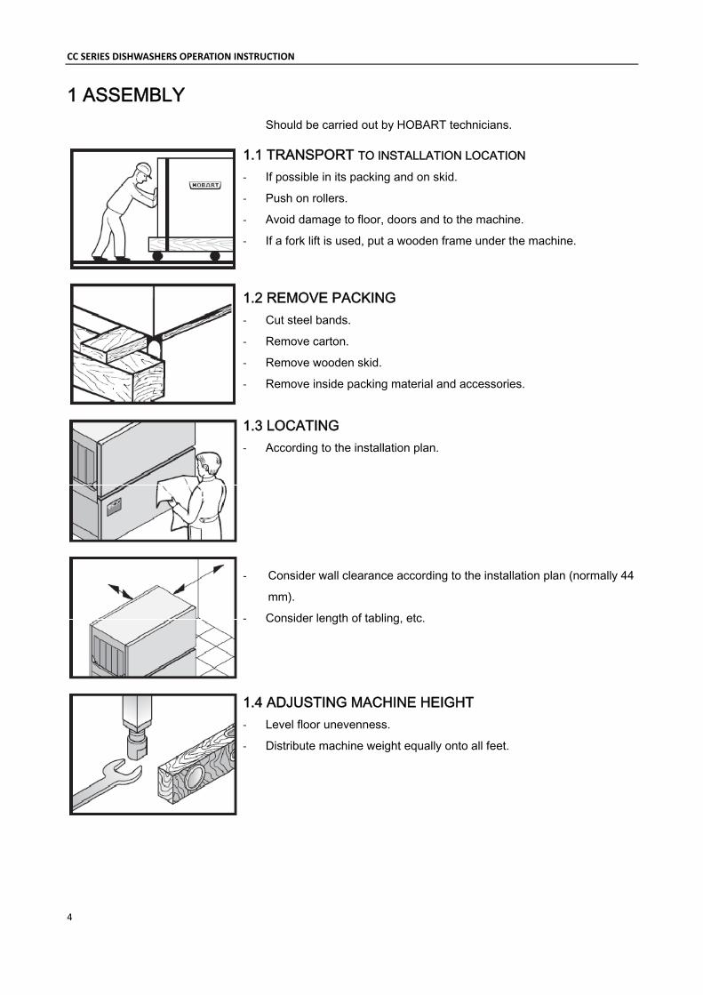
1 ASSEMBLY Should be carried out by HOBART technicians.
1.1 TRANSPORT TO INSTALLATION LOCATION
‐ If possible in its packing and on skid.
‐ Push on rollers.
‐ Avoid damage to floor, doors and to the machine.
‐ If a fork lift is used, put a wooden frame under the machine.
1.2 REMOVE PACKING ‐ Cut steel bands.
‐ Remove carton.
‐ Remove wooden skid.
‐ Remove inside packing material and accessories.
1.3 LOCATING ‐ According to the installation plan.
‐ Consider wall clearance according to the installation plan (normally 44
mm).
‐ Consider length of tabling, etc.
1.4 ADJUSTING MACHINE HEIGHT ‐ Level floor unevenness.
‐ Distribute machine weight equally onto all feet.
GB F NL
5
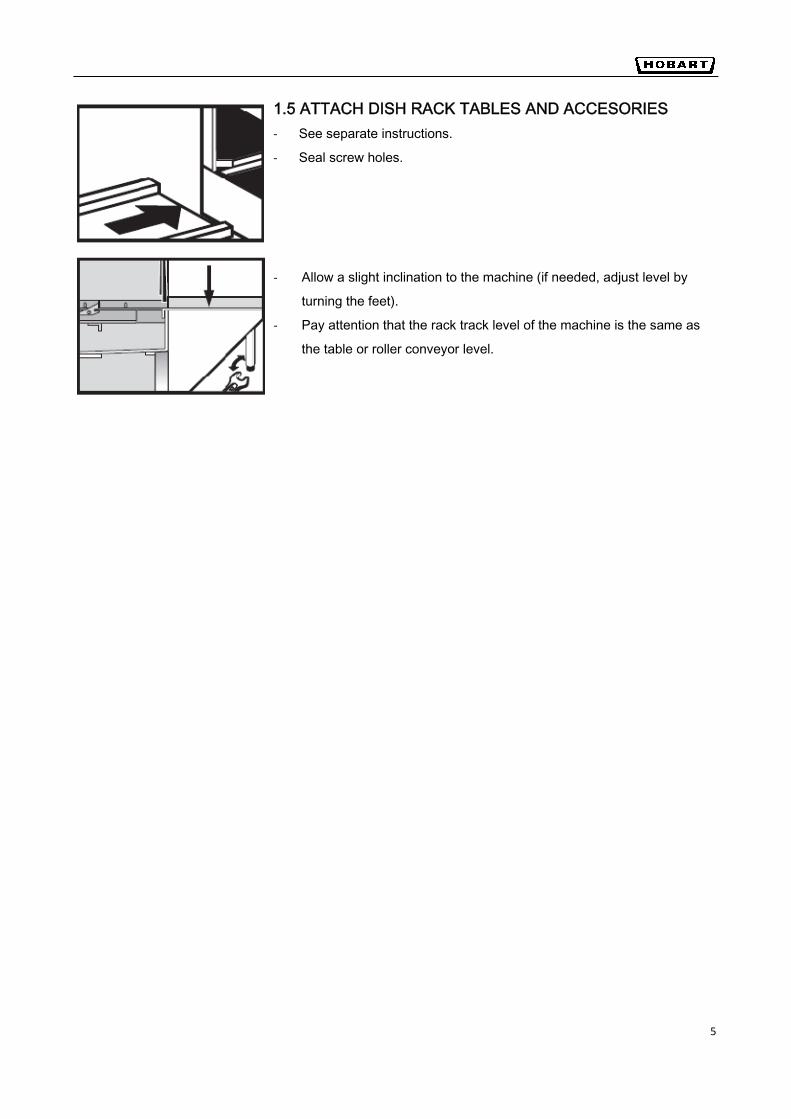
1.5 ATTACH DISH RACK TABLES AND ACCESORIES ‐ See separate instructions.
‐ Seal screw holes.
‐ Allow a slight inclination to the machine (if needed, adjust level by
turning the feet).
‐ Pay attention that the rack track level of the machine is the same as
the table or roller conveyor level.
CC SERIES DISHWASHERS OPERATION INSTRUCTION
6
2 CONNECTIONS
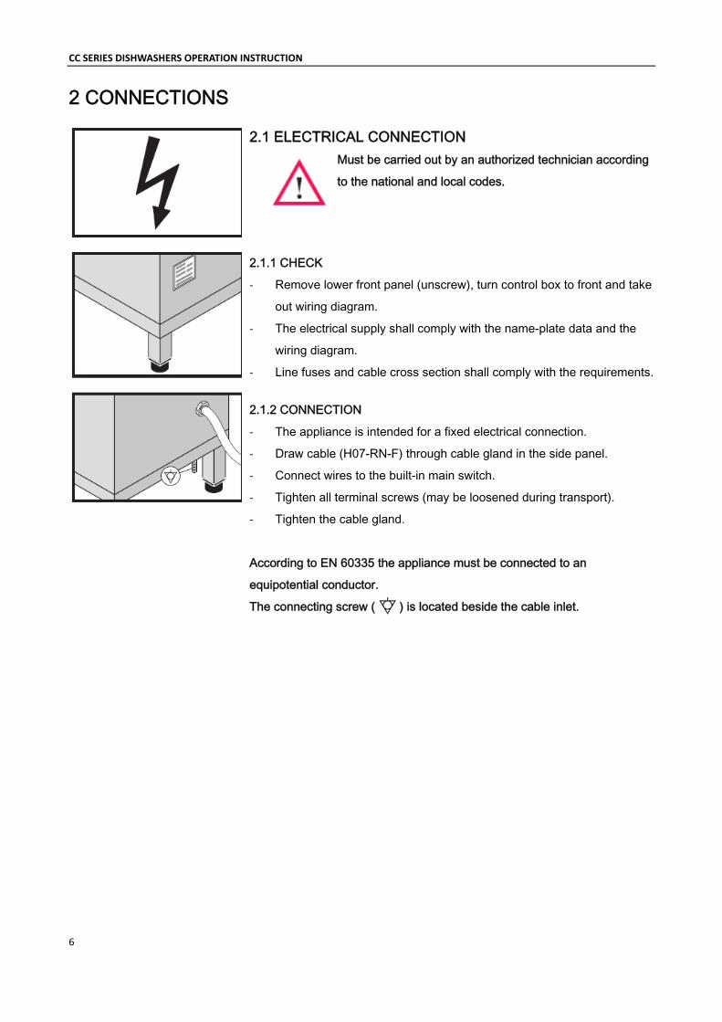
2.1 ELECTRICAL CONNECTION Must be carried out by an authorized technician according
to the national and local codes.
2.1.1 CHECK
‐ Remove lower front panel (unscrew), turn control box to front and take
out wiring diagram.
‐ The electrical supply shall comply with the name-plate data and the
wiring diagram.
‐ Line fuses and cable cross section shall comply with the requirements.
2.1.2 CONNECTION
‐ The appliance is intended for a fixed electrical connection.
‐ Draw cable (H07-RN-F) through cable gland in the side panel.
‐ Connect wires to the built-in main switch.
‐ Tighten all terminal screws (may be loosened during transport).
‐ Tighten the cable gland.
According to EN 60335 the appliance must be connected to an
equipotential conductor.
The connecting screw ( ) is located beside the cable inlet.
7
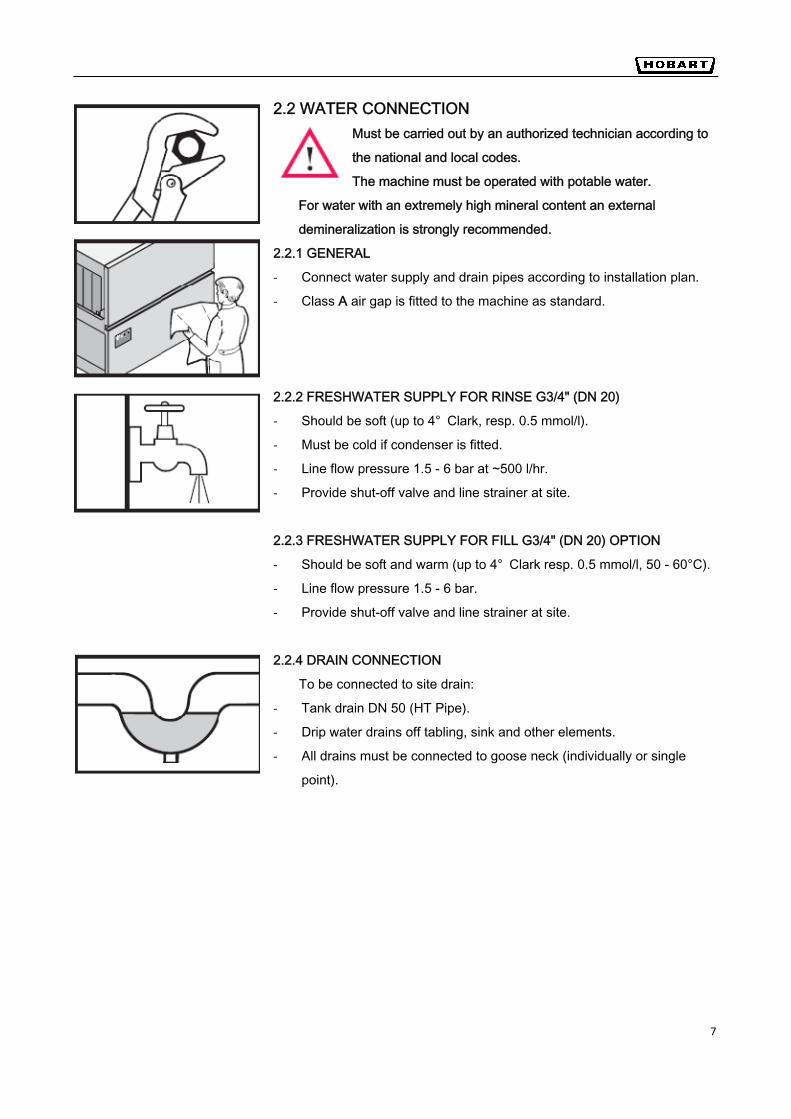
2.2 WATER CONNECTION Must be carried out by an authorized technician according to
the national and local codes.
The machine must be operated with potable water.
For water with an extremely high mineral content an external
demineralization is strongly recommended.
2.2.1 GENERAL
‐ Connect water supply and drain pipes according to installation plan.
‐ Class A air gap is fitted to the machine as standard.
2.2.2 FRESHWATER SUPPLY FOR RINSE G3/4" (DN 20)
‐ Should be soft (up to 4° Clark, resp. 0.5 mmol/l).
‐ Must be cold if condenser is fitted.
‐ Line flow pressure 1.5 - 6 bar at ~500 l/hr.
‐ Provide shut-off valve and line strainer at site.
2.2.3 FRESHWATER SUPPLY FOR FILL G3/4" (DN 20) OPTION
‐ Should be soft and warm (up to 4° Clark resp. 0.5 mmol/l, 50 - 60°C).
‐ Line flow pressure 1.5 - 6 bar.
‐ Provide shut-off valve and line strainer at site.
2.2.4 DRAIN CONNECTION
To be connected to site drain:
‐ Tank drain DN 50 (HT Pipe).
‐ Drip water drains off tabling, sink and other elements.
‐ All drains must be connected to goose neck (individually or single
point).
F NL
CC SERIES DISHWASHERS OPERATION INSTRUCTION
8
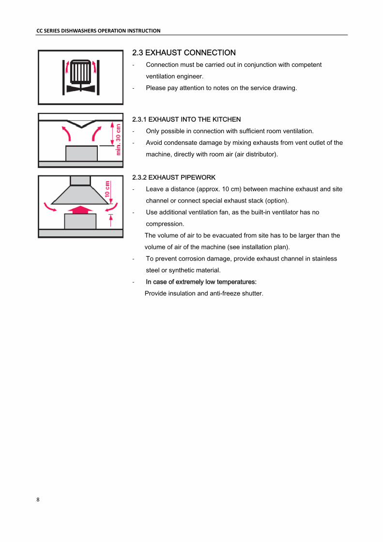
2.3 EXHAUST CONNECTION ‐ Connection must be carried out in conjunction with competent
ventilation engineer.
‐ Please pay attention to notes on the service drawing.
2.3.1 EXHAUST INTO THE KITCHEN
‐ Only possible in connection with sufficient room ventilation.
‐ Avoid condensate damage by mixing exhausts from vent outlet of the
machine, directly with room air (air distributor).
2.3.2 EXHAUST PIPEWORK
‐ Leave a distance (approx. 10 cm) between machine exhaust and site
channel or connect special exhaust stack (option).
‐ Use additional ventilation fan, as the built-in ventilator has no
compression.
The volume of air to be evacuated from site has to be larger than the
volume of air of the machine (see installation plan).
‐ To prevent corrosion damage, provide exhaust channel in stainless
steel or synthetic material.
‐ In case of extremely low temperatures:
Provide insulation and anti-freeze shutter.
DE GB F NL
9
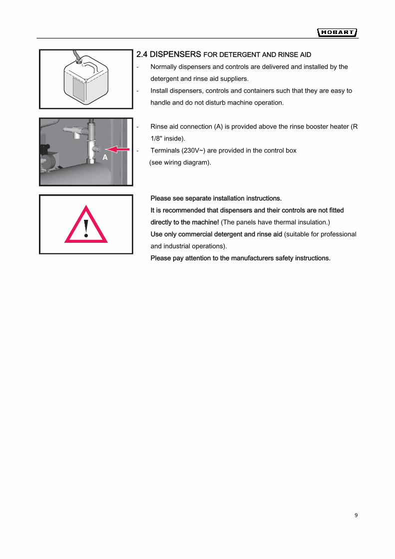
2.4 DISPENSERS FOR DETERGENT AND RINSE AID
‐ Normally dispensers and controls are delivered and installed by the
detergent and rinse aid suppliers.
‐ Install dispensers, controls and containers such that they are easy to
handle and do not disturb machine operation.
‐ Rinse aid connection (A) is provided above the rinse booster heater (R
1/8" inside).
‐ Terminals (230V~) are provided in the control box
(see wiring diagram).
Please see separate installation instructions.
It is recommended that dispensers and their controls are not fitted
directly to the machine! (The panels have thermal insulation.)
Use only commercial detergent and rinse aid (suitable for professional
and industrial operations).
Please pay attention to the manufacturers safety instructions.

CC SERIES DISHWASHERS OPERATION INSTRUCTION
10
3 CONTROLS
➀ Program selector switch (illuminates during operation) By turning the selector switch to Fill position, the machine will be switched on automatically and filled up (tank heating and rinse booster heater start automatically). By turning the selector switch to 0 position, the machine (heating and conveyor) will be shut off (e.g. during long term interruption). By turning the selector switch to Drain position, the machine will be emptied (e.g. end of operation).
➁ Power light (green) Indicates that the machine is connected to power supply.
➂ Conveyor ON button By pushing this button conveyor and wash operation start.
➃ Conveyor OFF button Pushing this button switches the conveyor and wash operation off ("Stand-By" Mode)
➄ Temperature indicator Wash (°C) Indicates the current temperature of the wash tank.
➅ Temperature indicator Rinse (°C) Indicates the current temperature of the final rinse water.
➆ Emergency Stop button Switches the machine off. Must be unlocked for operation.
② ③ ④ ⑦
① ⑤ ⑥
11
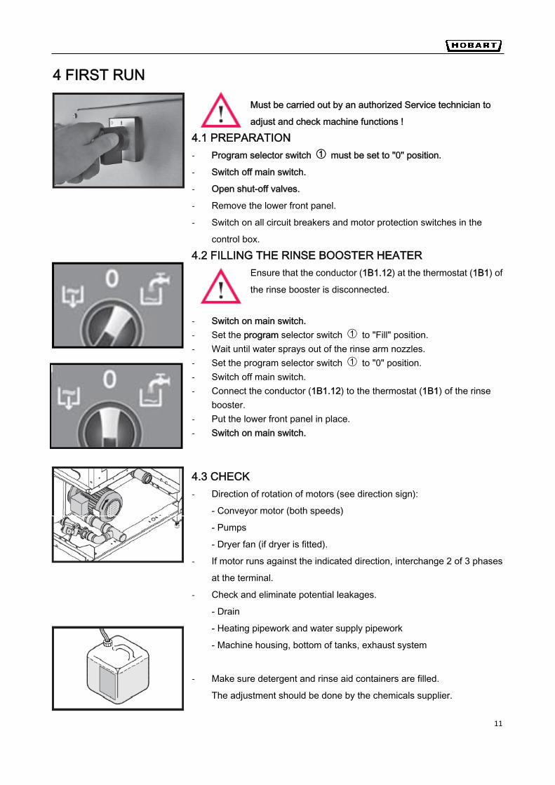
4 FIRST RUN
Must be carried out by an authorized Service technician to
adjust and check machine functions !
4.1 PREPARATION ‐ Program selector switch ➀ must be set to "0" position.
‐ Switch off main switch.
‐ Open shut-off valves.
‐ Remove the lower front panel.
‐ Switch on all circuit breakers and motor protection switches in the
control box.
4.2 FILLING THE RINSE BOOSTER HEATER Ensure that the conductor (1B1.12) at the thermostat (1B1) of
the rinse booster is disconnected.
‐ Switch on main switch. ‐ Set the program selector switch ➀ to "Fill" position. ‐ Wait until water sprays out of the rinse arm nozzles. ‐ Set the program selector switch ➀ to "0" position. ‐ Switch off main switch. ‐ Connect the conductor (1B1.12) to the thermostat (1B1) of the rinse
booster. ‐ Put the lower front panel in place. ‐ Switch on main switch.
4.3 CHECK ‐ Direction of rotation of motors (see direction sign):
- Conveyor motor (both speeds)
- Pumps
- Dryer fan (if dryer is fitted).
‐ If motor runs against the indicated direction, interchange 2 of 3 phases
at the terminal.
‐ Check and eliminate potential leakages.
- Drain
- Heating pipework and water supply pipework
- Machine housing, bottom of tanks, exhaust system
‐ Make sure detergent and rinse aid containers are filled.
The adjustment should be done by the chemicals supplier.

CC SERIES DISHWASHERS OPERATION INSTRUCTION
12
5 OPERATION 5.1 PREPARATION
Put the flat strainers in place. Put the strainer baskets in place. Set wash arms in place: Upper: set wash arm in slide guides, move to end position and drop-in over stop unit. Lower: move wash arm in slide guides to end position and click into place.
Set rinse arms in place: Put curtains in place Close inspection doors. Upper: set rinse arm in back (see chapter 7). Ensure sufficient detergent and opening, move from below into rinse aid is available in the right guide and click into place. containers. Lower: move rinse arm in guides to end and click into place.
Switch on main switch. Set program selector switch ➀ to Open shut-off valve at site. "Fill" position. The machine starts
fill and heating automatically.
13
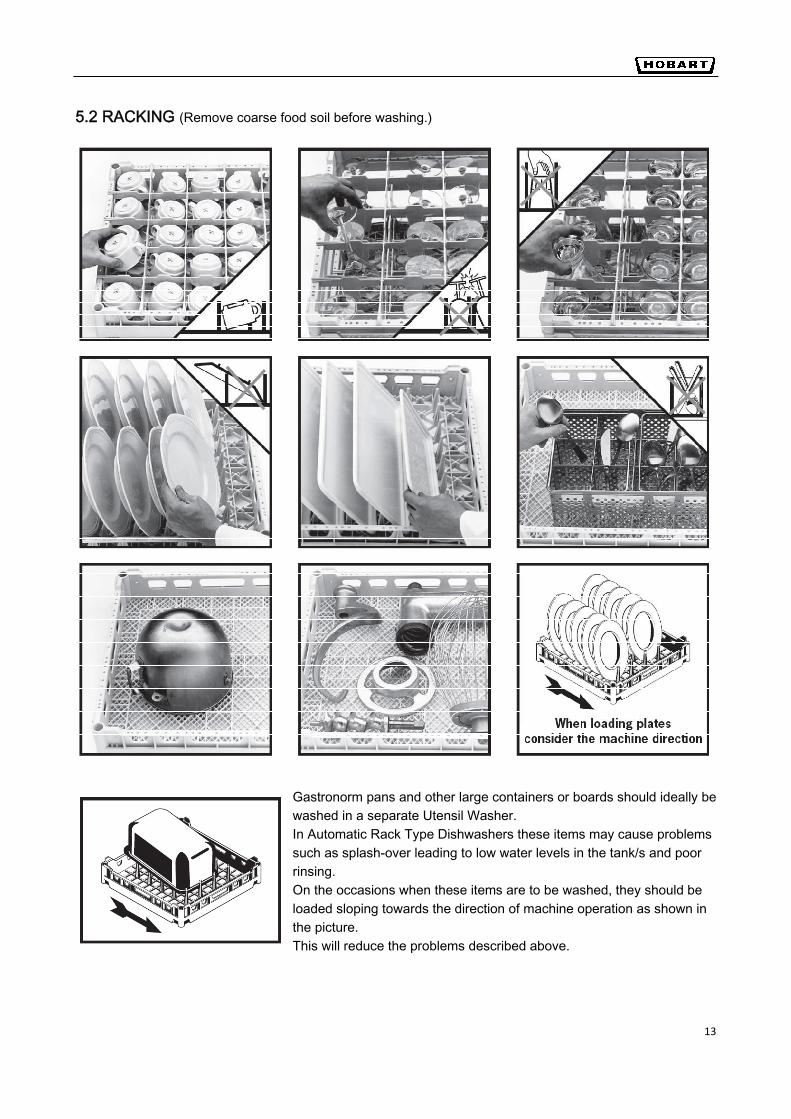
5.2 RACKING (Remove coarse food soil before washing.)
Gastronorm pans and other large containers or boards should ideally be washed in a separate Utensil Washer. In Automatic Rack Type Dishwashers these items may cause problems such as splash-over leading to low water levels in the tank/s and poor rinsing. On the occasions when these items are to be washed, they should be loaded sloping towards the direction of machine operation as shown in the picture. This will reduce the problems described above.
DE
CC SERIES DISHWASHERS OPERATION INSTRUCTION
14
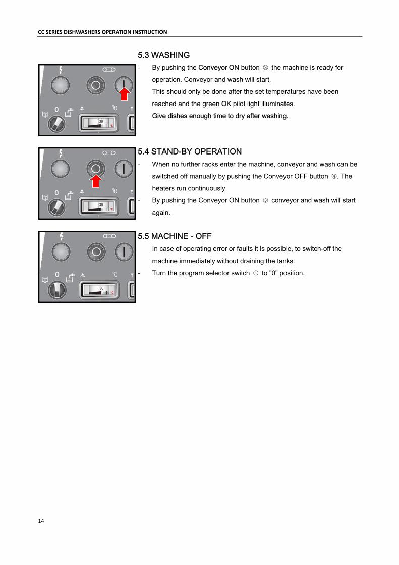
5.3 WASHING ‐ By pushing the Conveyor ON button ➂ the machine is ready for
operation. Conveyor and wash will start.
This should only be done after the set temperatures have been
reached and the green OK pilot light illuminates.
Give dishes enough time to dry after washing.
5.4 STAND-BY OPERATION ‐ When no further racks enter the machine, conveyor and wash can be
switched off manually by pushing the Conveyor OFF button ➃. The
heaters run continuously.
‐ By pushing the Conveyor ON button ➂ conveyor and wash will start
again.
5.5 MACHINE - OFF
In case of operating error or faults it is possible, to switch-off the
machine immediately without draining the tanks.
‐ Turn the program selector switch ➀ to "0" position.
15
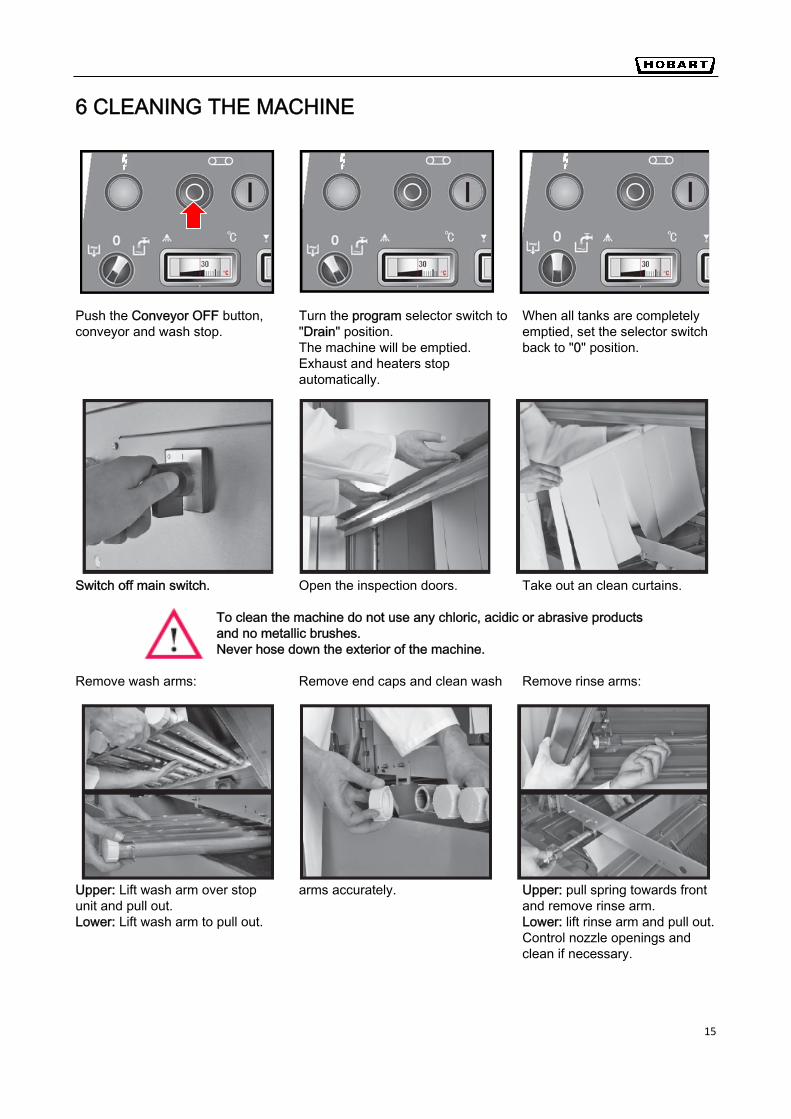
6 CLEANING THE MACHINE
Push the Conveyor OFF button, Turn the program selector switch to When all tanks are completely conveyor and wash stop. "Drain" position. emptied, set the selector switch
The machine will be emptied. back to "0" position. Exhaust and heaters stop automatically.
Switch off main switch. Open the inspection doors. Take out an clean curtains. To clean the machine do not use any chloric, acidic or abrasive products and no metallic brushes. Never hose down the exterior of the machine.
Remove wash arms: Remove end caps and clean wash Remove rinse arms:
Upper: Lift wash arm over stop arms accurately. Upper: pull spring towards front unit and pull out. and remove rinse arm. Lower: Lift wash arm to pull out. Lower: lift rinse arm and pull out.
Control nozzle openings and clean if necessary.
DE
CC SERIES DISHWASHERS OPERATION INSTRUCTION
16
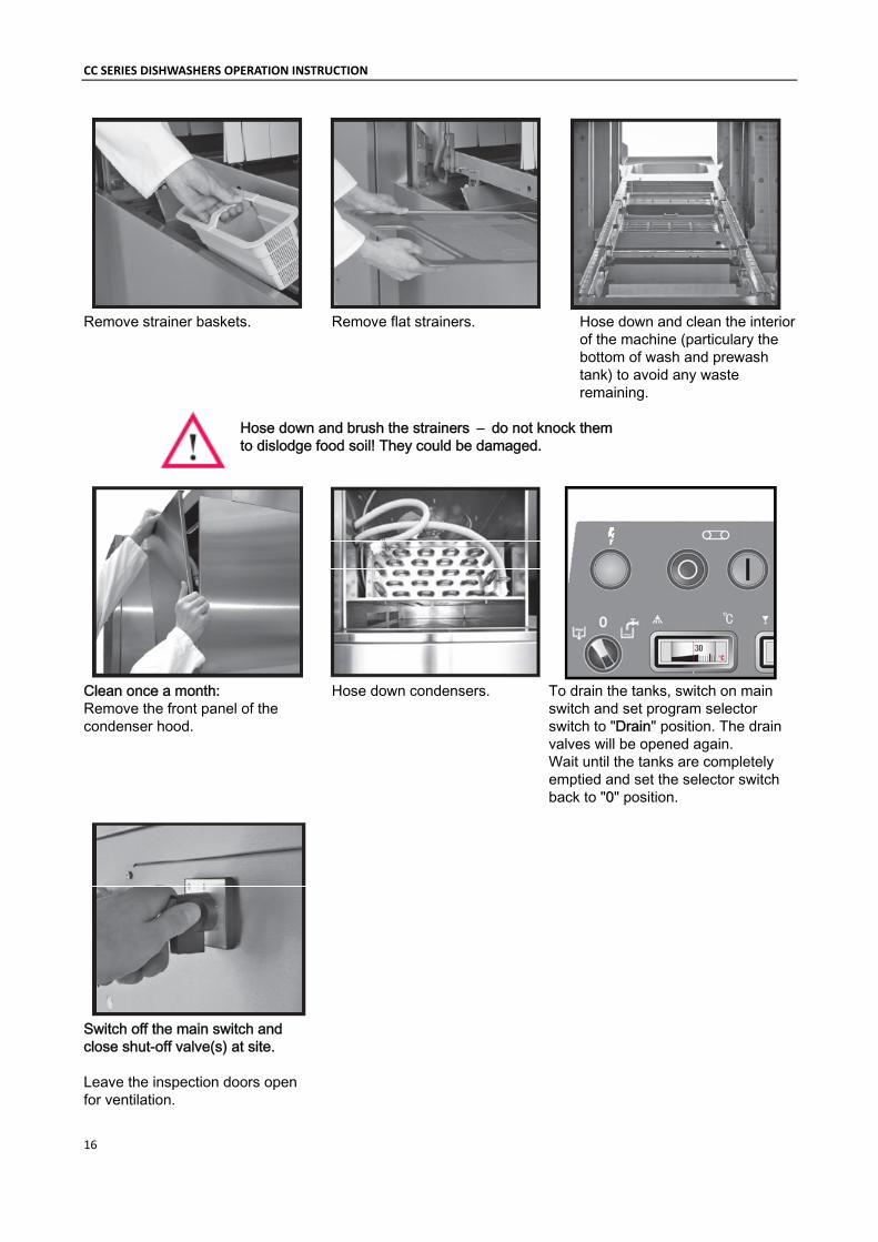
Remove strainer baskets. Remove flat strainers. Hose down and clean the interior of the machine (particulary the bottom of wash and prewash tank) to avoid any waste remaining.
Hose down and brush the strainers – do not knock them to dislodge food soil! They could be damaged.
Clean once a month: Hose down condensers. To drain the tanks, switch on main Remove the front panel of the switch and set program selector condenser hood. switch to "Drain" position. The drain
valves will be opened again. Wait until the tanks are completely emptied and set the selector switch back to "0" position.
Switch off the main switch and close shut-off valve(s) at site. Leave the inspection doors open for ventilation.
17
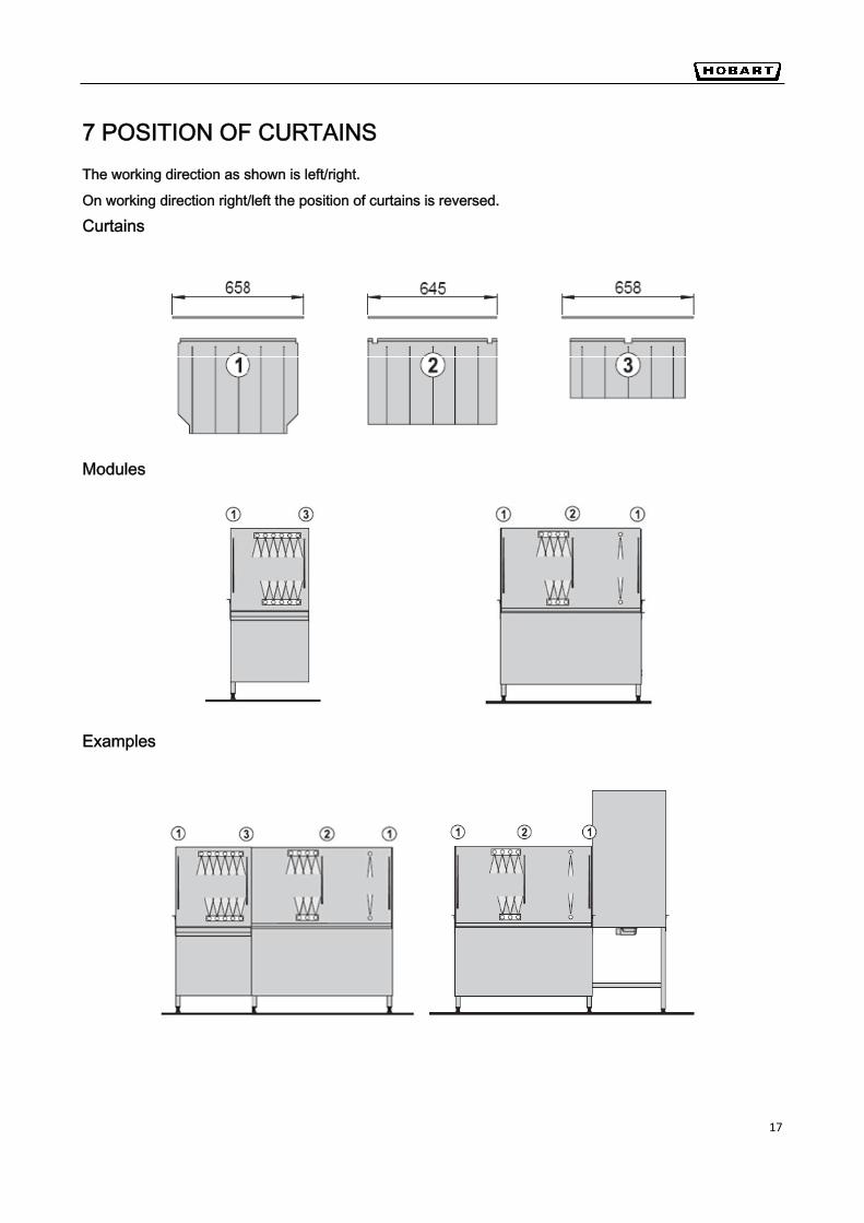
7 POSITION OF CURTAINS The working direction as shown is left/right.
On working direction right/left the position of curtains is reversed.
Curtains
Modules
Examples
DE
CC SERIES DISHWASHERS OPERATION INSTRUCTION
18
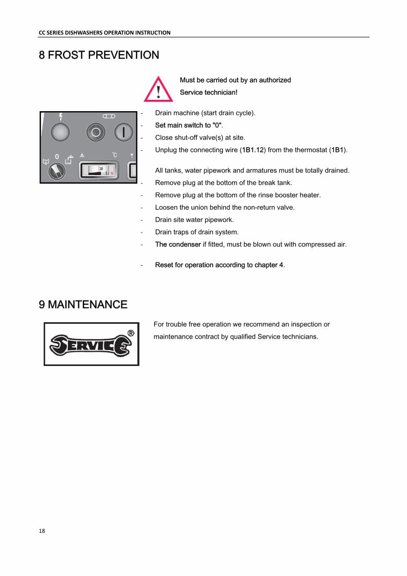
8 FROST PREVENTION
Must be carried out by an authorized
Service technician!
‐ Drain machine (start drain cycle).
‐ Set main switch to "0".
‐ Close shut-off valve(s) at site.
‐ Unplug the connecting wire (1B1.12) from the thermostat (1B1).
All tanks, water pipework and armatures must be totally drained.
‐ Remove plug at the bottom of the break tank.
‐ Remove plug at the bottom of the rinse booster heater.
‐ Loosen the union behind the non-return valve.
‐ Drain site water pipework.
‐ Drain traps of drain system.
‐ The condenser if fitted, must be blown out with compressed air.
‐ Reset for operation according to chapter 4.
9 MAINTENANCE For trouble free operation we recommend an inspection or
maintenance contract by qualified Service technicians.
DE
19
10 TROUBLESHOOTING FAULT CAUSE REMEDYInitial booster fill not possible. Shut off valve at site closed. Open the shut off valve at site and restart.
Fill system defective. Call the after sales service. Tank fill too slow. Line strainer of fill clogged. Clean line strainer.
Solenoid valve defective. Call the after sales service. Shut off valve at site not correctly open.
Open shut off valve completely.
Tank not filled to correct level. Fill cycle too short. Call the after sales service. Steam escapes from loading or exit section.
Exhaust extraction too low. Call the after sales service. Wrong position of curtains. Check curtains (see chapter 7).
Temperatures too low. Too much exhaust extraction. Call the after sales service. Heaters defective. Check heaters, steam or high pressure hot
water supply systems. If necessary, call the after sales service.
Washware soiled after dishwashing.
Strainers wrongly positioned. Check strainers.Curtains not fitted or wrongly placed. Check curtains (see chapter 7). Wash arm nozzles clogged. Clean the wash arms. Too low detergent concentration. Increase detergent dispensing. Too much foam. Use non-foaming detergent only. Excessive food debris entering machine.
Check pre-scrapping procedure.
Temperatures too low. Check heating system. Wash / Rinse fault. Call the after sales service. Conveyor speed too high. Select lower speed.
Streaks and spots on washware.
Strainers wrongly positioned. Check strainers.Wash water splashes into rinse section.
Check curtains (see chapter 7).
Rinse nozzles clogged. Clean rinse nozzles. Incorrect rinse aid dispensing. Adjust rinse aid dispenser. Too high mineral content of rinse water.
Use of demineralized water recommended.
Washware do not dry. Incorrect temperature or humidity of drying air.
Check heater and blower of drying unit.
Conveyor speed too high. Select lower speed. Inadequate rinse aid concentration. Increase concentration.
Drops on washware. Wrong rinse aid or inadequate concentration.
Check rinse aid / adjustment.
Dishes tilt over. Water pressure from below too high. Call the after sales service. Upper wash arms clogged. Remove wash arms and clean.


