MAR 2008 REV.- READ THIS INSTRUCTION MANUAL THOROUGHLY BEFORE INSTALLING, OPERATING, SERVICING OR MAINTAINING THE LIFT. SAVE THIS MANUAL. INSTALLATION and OPERATION MANUAL Snap-On Tools Corporation 1-800-268-7959 10K SCISSOR LIFT MODEL: EELR3__A (58/59/60/61) 6-3635
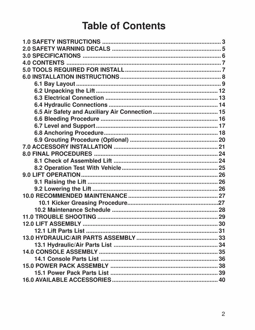
6.1 Bay Layout ......................................................................................... 96.2 Unpacking the Lift ........................................................................... 126.3 Electrical Connection ..................................................................... 136.4 Hydraulic Connections ................................................................... 146.5 Air Safety and Auxiliary Air Connection ........................................ 156.6 Bleeding Procedure ........................................................................ 166.7 Level and Support ........................................................................... 176.8 Anchoring Procedure...................................................................... 186.9 Grouting Procedure (Optional) ...................................................... 20
7.0 ACCESSORY INSTALLATION ................................................................ 218.0 FINAL PROCEDURES ............................................................................ 24
8.1 Check of Assembled Lift ................................................................ 248.2 Operation Test With Vehicle ........................................................... 25
9.0 LIFT OPERATION.................................................................................... 269.1 Raising the Lift ................................................................................ 269.2 Lowering the Lift ............................................................................. 26
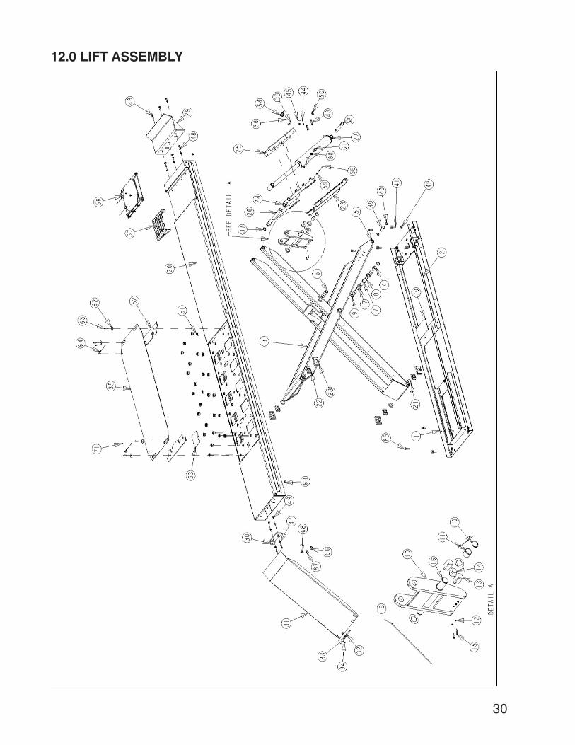
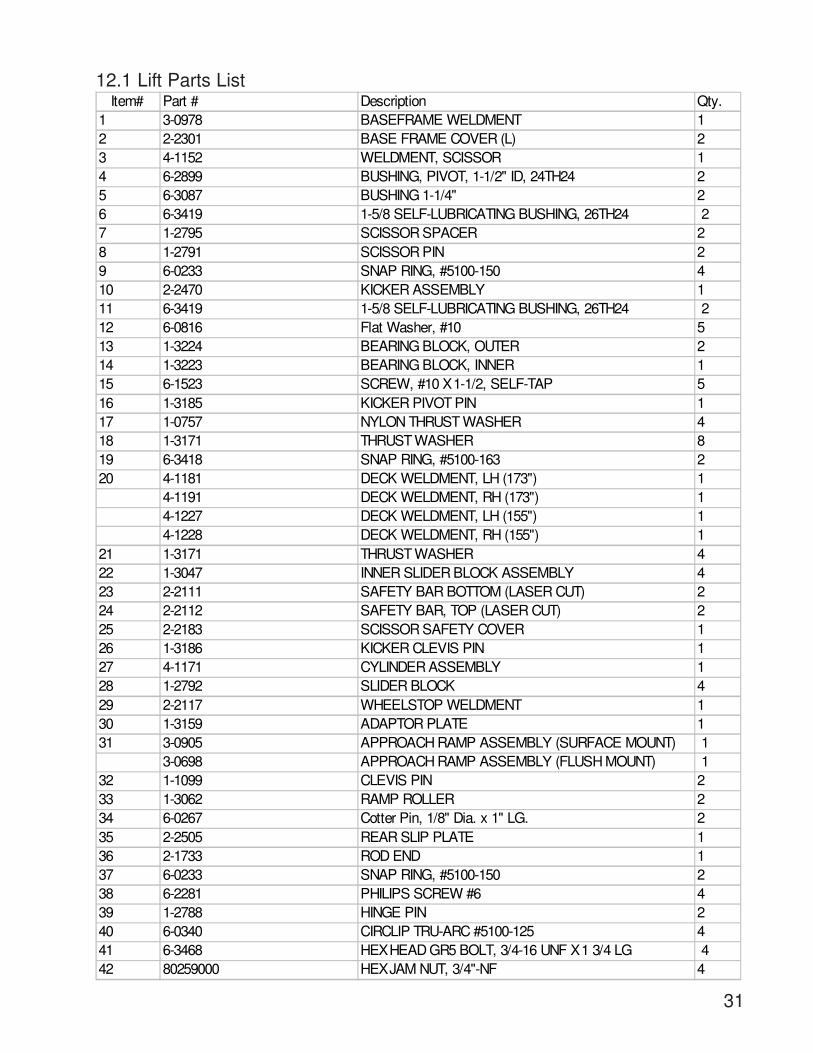
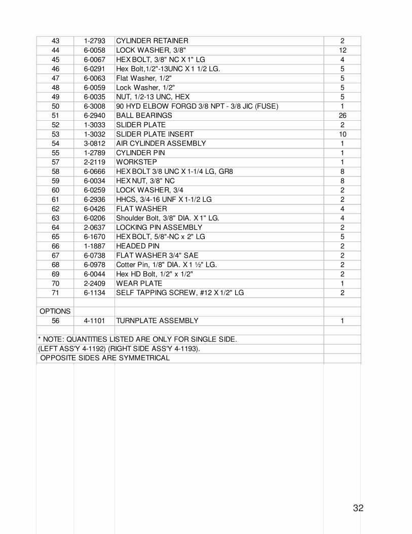
12.1 Lift Parts List ................................................................................. 3113.0 HYDRAULIC/AIR PARTS ASSEMBLY .................................................. 33
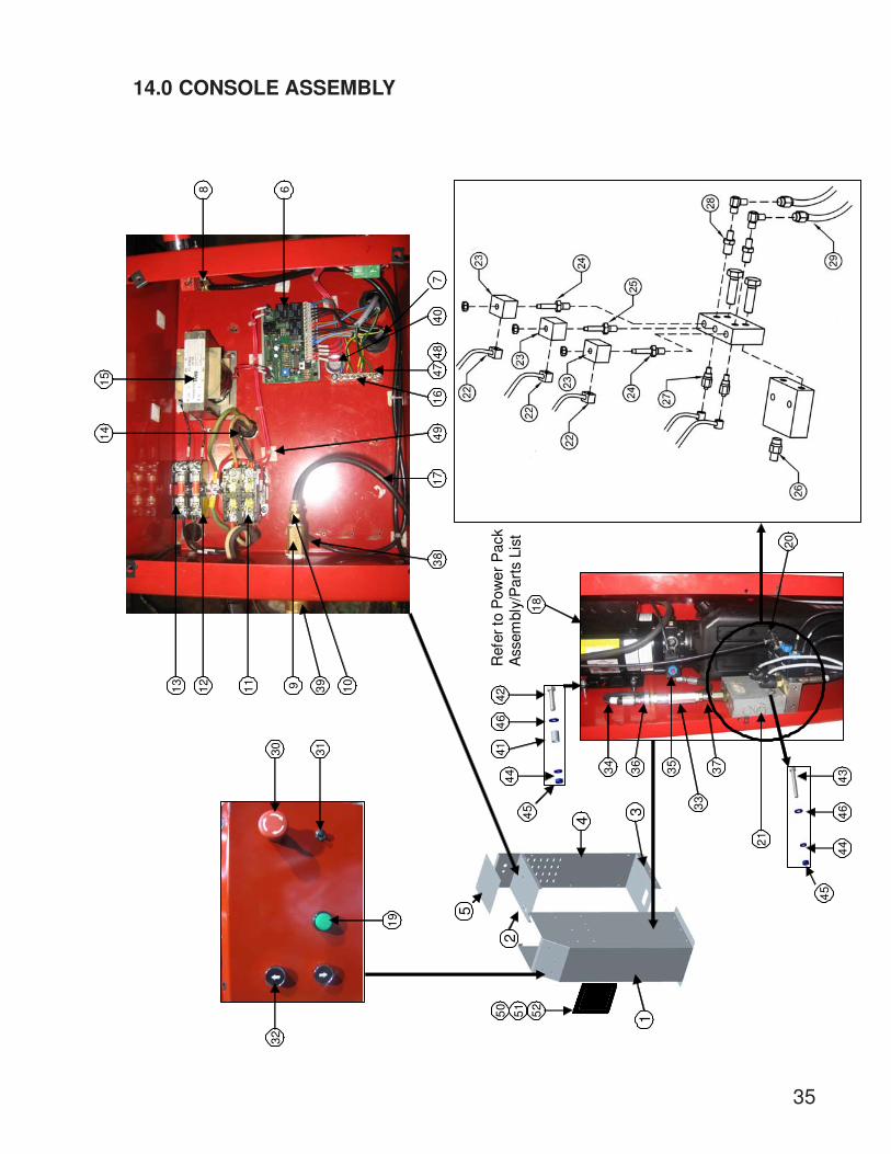
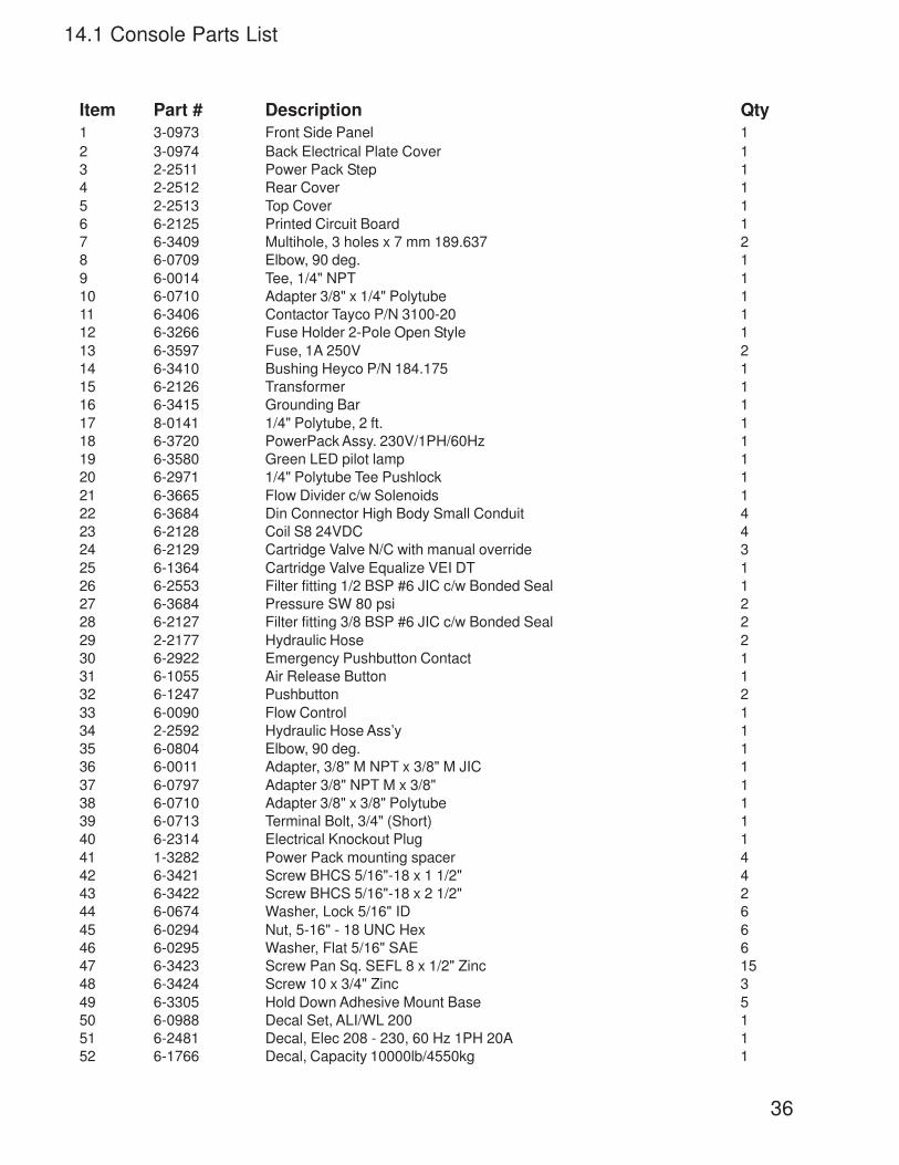
13.1 Hydraulic/Air Parts List ................................................................ 3414.0 CONSOLE ASSEMBLY ......................................................................... 35
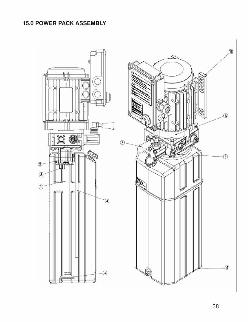
14.1 Console Parts List ........................................................................ 3615.0 POWER PACK ASSEMBLY .................................................................. 38
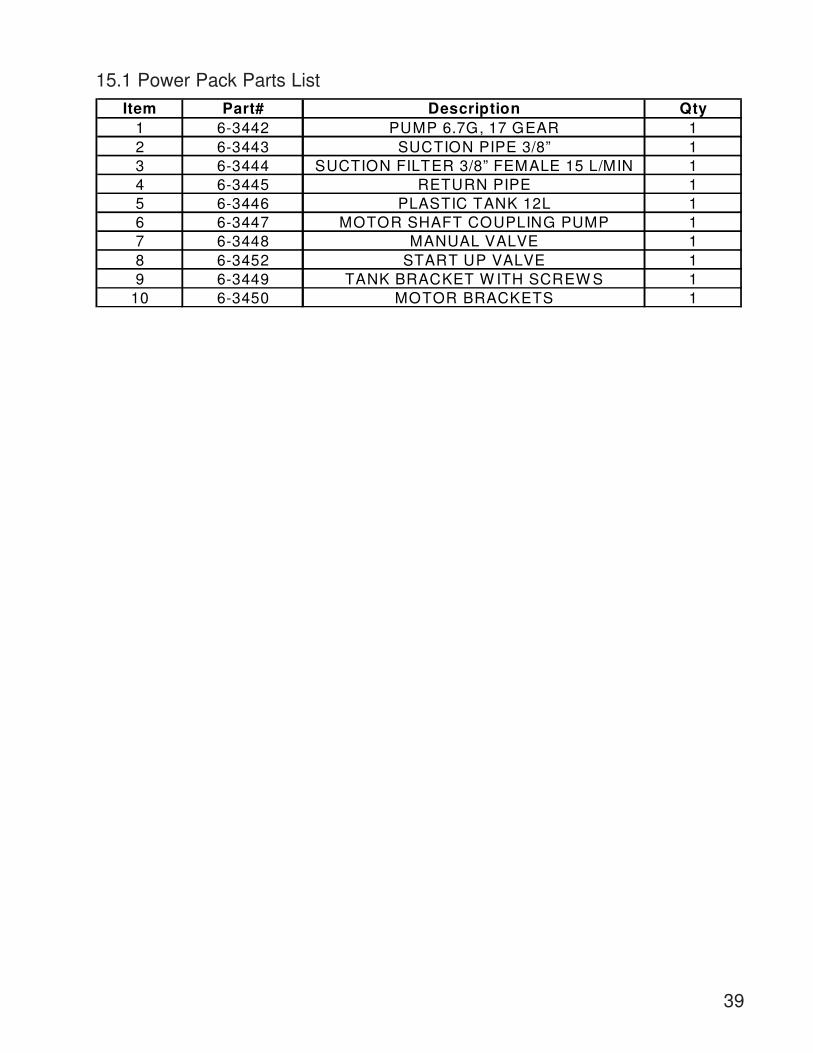
15.1 Power Pack Parts List .................................................................. 3916.0 AVAILABLE ACCESSORIES ................................................................. 40
3
1 Read all instructions and safety information in this manual and on the lift thoroughlybefore installing, operating, servicing, or maintaining the lift.
2 Inspect the lift DAILY. Do not operate if it malfunctions or problems have beenencountered.
3 Never attempt to overload the lift. The manufacturer’s rated capacity is shown on theidentification label on side of the deck. Do not override the operating controls or safetydevices.
4 Only trained and authorized personnel should operate the lift. Do not allow customersor bystanders to operate the lift or be in the lift area.
5 CAUTION! Never work under the lift unless mechanical safety locks are engaged.
6 Always keep the lift area free of obstruction and debris. Grease and oil spills shouldalways be cleaned up immediately.
7 Never raise a vehicle with passengers inside.
8 Always chock vehicle wheels before raising or lowering the lift.
9 Before lowering check the area for any obstructions including people.
10 To protect against risk of fire, do not operate the lift in the vicinity of open containers offlammable liquids.
11 Adequate ventilation should be provided when working on internal combustionengines.
12 Never open hydraulic lines under pressure.
READ AND SAVE THESE INSTRUCTIONS
1.0 SAFETY INSTRUCTIONS
When using this lift, basic safety precautions should always be followed, including the following:
4
Installation shall be performed in accordance with ANSO/ALI ALIS, Safety Requirements forInstallation and Service of Automotive Lifts.
For additional safety instructions regarding lifting, lift types, warning labels, preparing to lift,vehicle spotting, vehicle lifting, maintaining load stability, emergency procedures, vehiclelowering, lift limitations, lift maintenance, good shop practices, installation, operator trainingand owner/employer responsibilities, please refer to “Lifting It Right” (ALI/SM) and “SafetyTips” (ALI/ST).
For additional instruction on general requirements for lift operation, please refer to “AutomotiveLift-Safety Requirements For Operation, Inspection and Maintenance” (ANSI/ALI ALOIM).
ATTENTION! THIS LIFT IS INTENDED FOR INDOOR INSTALLATION ONLY. ITIS PROHIBITED TO INSTALL THIS PRODUCT OUTDOORS. FAILURE TOADHERE WILL RESULT IN LOSS OF WARRANTY AND POSSIBLE DAMAGETO THE EQUIPMENT.
5
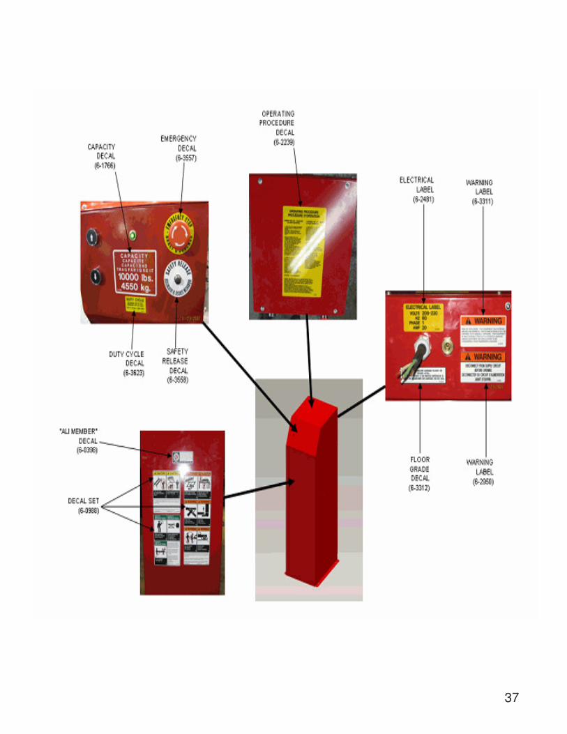
2.0 SAFETY WARNING DECALS
Be sure the operator is aware and understands all safety warning labels and followsthem accordingly.
6
Figure 1 Lift Dimensions
3.0 SPECIFICATIONSMaximum Capacity: 10 000 lbs 4 536 kgOverall W idth (min-max): 92-1/2 - 94-1/2 Inches 2350-2400 mm
Maximum Raised Height: 73-3/8 Inches 1861 mmMinimum Lowered Height: 9 Inches 229 mmRunway W idth 26 Inches 660 mmLifting Time:Power Requirements:Air Supply requirements:Hydraulic Oil Capacity: Tank s ize: 4.0 gal Lift uses: 3.0 galOil Type:
Overall Length:
85 seconds at max. capacity
ISO 32 (10 weight) hydraulic oil
220V, 1 Ph, 60 Hz, 25A90 to 120 psi
7
The complete lift is contained in two (2) packages:1. The main structural components are pre-assembled and packaged on top of each
other.2. The remaining parts are packed in a console/accessory box. Refer to the packing
slip inside for a list of contents.
Components include:
1pc. – Left Side Main Frame Assembly: Runway, Scissors and Base Frame1pc. – Right Side Main Frame Assembly: Runway, Scissors and Base Frame1pc. – Console and accessory box. (See accessory box list for contents)1pc – Grout container1pc. – Customer care kit including manuals
� Hammer Drill or similar, 1/4” and 1/2” Concrete Drill Bits� 4’ Level� SAE Wrenches and Sockets� Hammer� Pry Bar – 5’ Long� Chalk Line� Tape Measure� Side Cutters� Screw Drivers� Hydraulic Fluid ISO 32 (10 weight hydraulic oil) - 15 liters/4 Gallons� Funnel� Utility Knife� Torque Wrench
Recommended:� Laser Leveler� Plumb Bob� Impact Gun� Boom and/or Engine Hoist� 8’ Sling� Engine Crane� Apply LOCTITE #242 on required fasteners where symbol is shown.
If fasteners are removed reapply LOCTITE before re-installing.
4.0 CONTENTS
5.0 TOOLS REQUIRED FOR INSTALL
8
IMPORTANT: It is the user’s responsibility to provide a satisfactory installation area for thelift. Lifts should only be installed on a level concrete floor with a minimum thickness of fourand a quarter inches (4¼”) or 108 mm. Concrete must have a minimum strength of 3000psi or 21 MPa and should be aged thirty (30) days prior to installation. Please consult thearchitect, contractor or engineer if doubt exists as to the strength and feasibility of the floorto enable proper lift installation and operation.
IMPORTANT: It is the user’s responsibility to provide all wiring for electrical hook-up priorto installation and to ensure that the electrical installation conforms to local building codes.Where required, it is the user’s responsibility to provide an electrical isolation switch lo-cated in close proximity to the lift that will enable emergency stop capability and isolateelectrical power from the lift for any servicing requirements.
6.0 INSTALLATION INSTRUCTIONS
When the lift arrives on site, please read the Installers manual completely. Check the contentsto make sure no parts are missing before starting installation. Gather all of the tools listedand make sure that the instructions are fully understood before commencing with theinstallation.
NODrains.
NODepressions.
NOHoles or Pits.
In shaded area around lift.
If more than ¼” depression in the kicker area (10” span) , this area must be filled and leveled.
Kicker Area
WARNING: The floor surface must be inspected and the below requirements must be met.
9
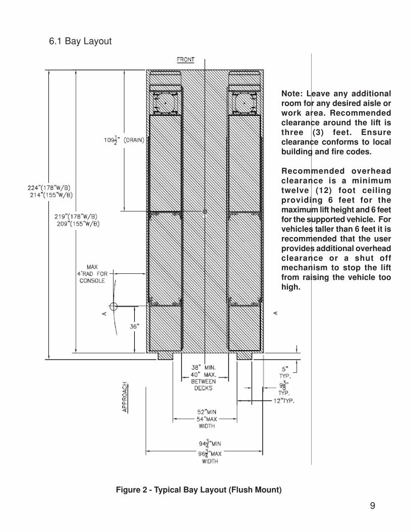
Figure 2 - Typical Bay Layout (Flush Mount)
6.1 Bay Layout
Note: Leave any additionalroom for any desired aisle orwork area. Recommendedclearance around the lift isthree (3) feet. Ensureclearance conforms to localbuilding and fire codes.
Recommended overheadclearance is a minimumtwelve (12) foot ceilingproviding 6 feet for themaximum lift height and 6 feetfor the supported vehicle. Forvehicles taller than 6 feet it isrecommended that the userprovides additional overheadclearance or a shut offmechanism to stop the liftfrom raising the vehicle toohigh.
10
Figure 3 - Typical Bay Layout (Surface Mount)
Note: Leave any additional room forany desired aisle or work area.Recommended clearance around thelift is three (3) feet. Ensure clearanceconforms to local building and firecodes.
Recommended overhead clearanceis a minimum twelve (12) foot ceilingproviding 6 feet for the maximum liftheight and 6 feet for the supportedvehicle. For vehicles taller than 6 feetit is recommended that the userprovides additional overheadclearance or a shut off mechanismto stop the lift from raising the vehicletoo high.
11
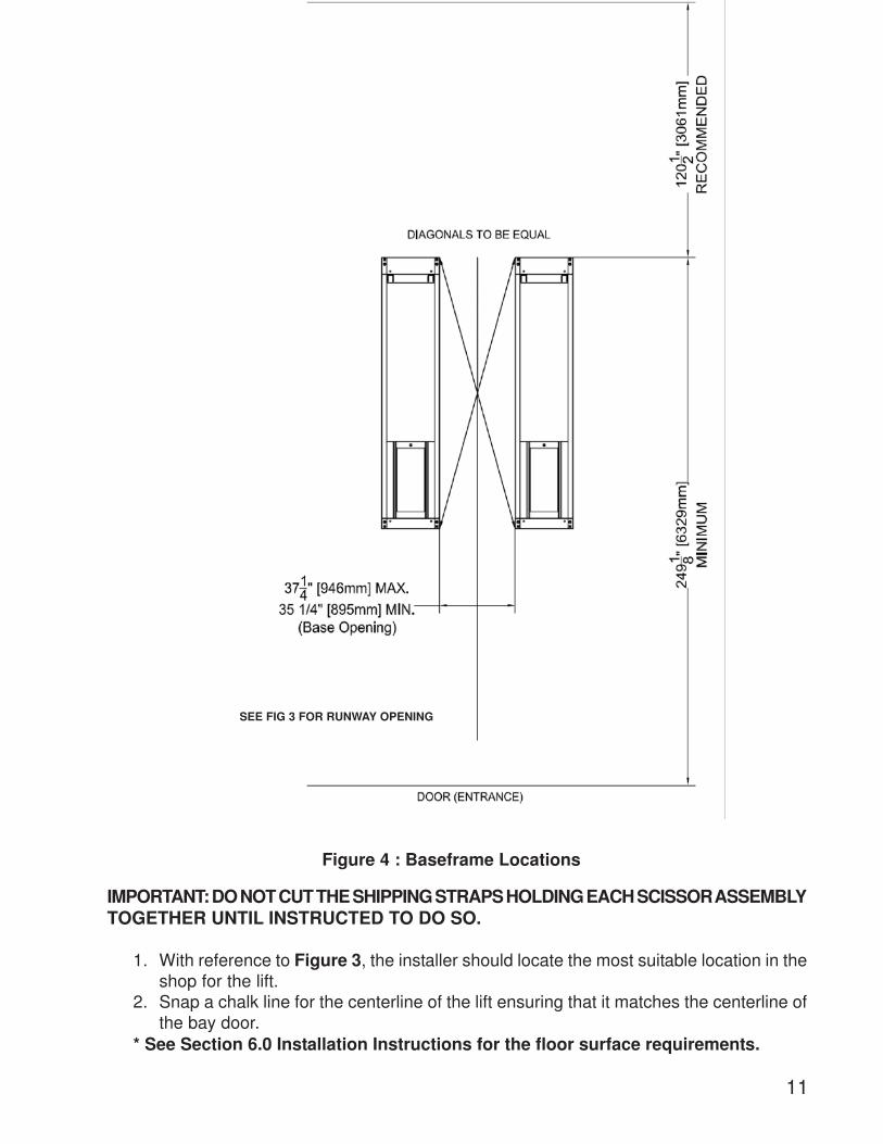
Figure 4 : Baseframe Locations
IMPORTANT: DO NOT CUT THE SHIPPING STRAPS HOLDING EACH SCISSOR ASSEMBLYTOGETHER UNTIL INSTRUCTED TO DO SO.
1. With reference to Figure 3, the installer should locate the most suitable location in theshop for the lift.
2. Snap a chalk line for the centerline of the lift ensuring that it matches the centerline ofthe bay door.
* See Section 6.0 Installation Instructions for the floor surface requirements.
SEE FIG 3 FOR RUNWAY OPENING
12
3. Measure and snap two (2) parallel chalk lines on either side the centerline for theinside edges of the baseframes. Refer to Figure 4 for the dimensions necessary toprovide the desired width between the two runways. A distance of 35 ¼” (895mm)between the baseframes will provide the standard width of 38” between the inside ofthe runways.
4. Measure and snap a chalk line parallel to the shop door for the front of the baseframes,a minimum distance of 249 1/8” (6328mm) is recommended.
5. Before proceeding, ensure that once the runways are installed adequate workspacewill remain in front of the lift. Refer to the minimum requirements listed in the installation and operation manual of any alignment equipment as needed.
1. Unpack the console and place it in the desired location at the rear of the lift. Theconsole can be placed on either the left or right hand side of the lift. The consolemust be located so the operator is always facing the lift.
2. Unpack the runways and lay each baseframe along the chalk lines.Do not remove the individual strapping on the runways until theyhave been positioned on the chalk lines.
3. Position the baseframes on chalk lines, and ensure that the runways are parallel.Before complete positioning of the last scissor be sure to remove the shipping tubes.Ensure that both the inside dimensions (front and back) of the baseframes as wellas the diagonal distances are equal.
Chalk Line
Center Line
Front
Rear
Turnplate
Jackbeam Rail
6.2 Unpacking the Lift
Ensure that the turnplate pockets are at the front, and that Jack Beamrails for each runway face each other.
4. Remove the remaining packing straps, and remove thehydraulic hoses and polytubes from under the runway. Hosesare located under the rear portion of the runway and arefactory pre-installedNote: do not pull excessively on the hoses as it maystrain the connections to the baseframe.
Ensure there are no holes, depressions, or drains inside the installation area.See Section 6.0 for requirements.
13
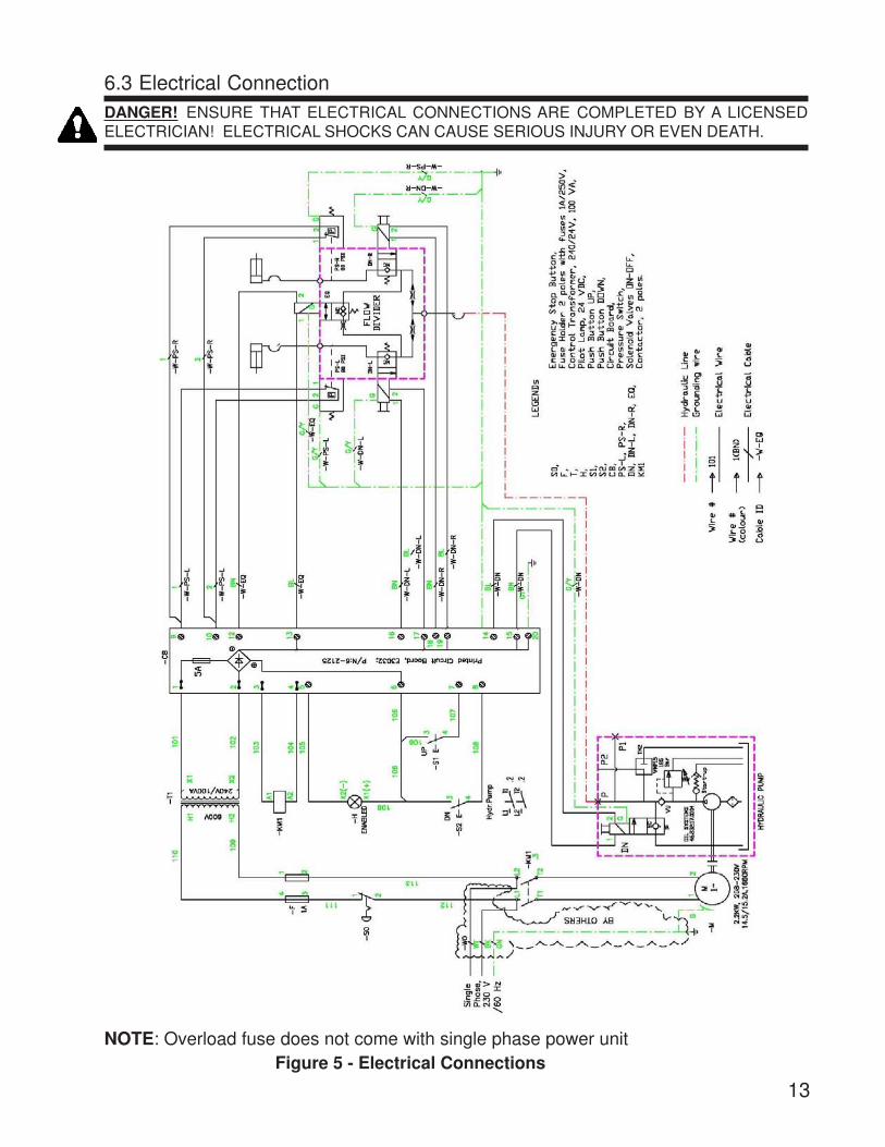
NOTE: Overload fuse does not come with single phase power unitFigure 5 - Electrical Connections
DANGER! ENSURE THAT ELECTRICAL CONNECTIONS ARE COMPLETED BY A LICENSEDELECTRICIAN! ELECTRICAL SHOCKS CAN CAUSE SERIOUS INJURY OR EVEN DEATH.
6.3 Electrical Connection
14
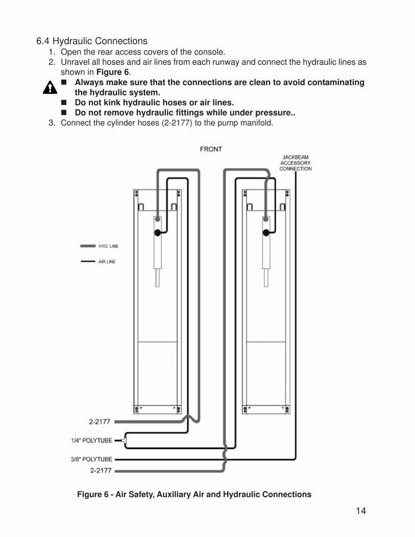
Figure 6 - Air Safety, Auxiliary Air and Hydraulic Connections
6.4 Hydraulic Connections1. Open the rear access covers of the console.2. Unravel all hoses and air lines from each runway and connect the hydraulic lines as
shown in Figure 6.����� Always make sure that the connections are clean to avoid contaminating
the hydraulic system.����� Do not kink hydraulic hoses or air lines.����� Do not remove hydraulic fittings while under pressure..
3. Connect the cylinder hoses (2-2177) to the pump manifold.
15
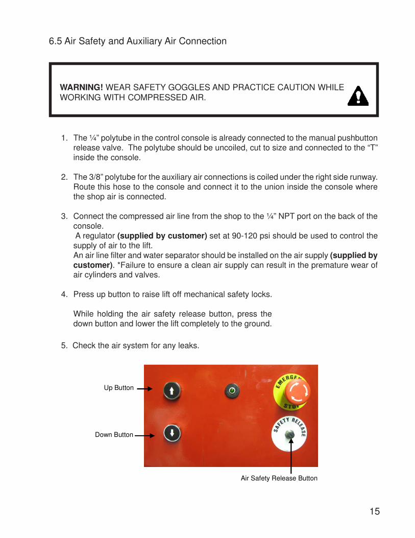
1. The ¼” polytube in the control console is already connected to the manual pushbuttonrelease valve. The polytube should be uncoiled, cut to size and connected to the “T”inside the console.
2. The 3/8” polytube for the auxiliary air connections is coiled under the right side runway.Route this hose to the console and connect it to the union inside the console wherethe shop air is connected.
3. Connect the compressed air line from the shop to the ¼” NPT port on the back of theconsole. A regulator (supplied by customer) set at 90-120 psi should be used to control thesupply of air to the lift.An air line filter and water separator should be installed on the air supply (supplied bycustomer). *Failure to ensure a clean air supply can result in the premature wear ofair cylinders and valves.
4. Press up button to raise lift off mechanical safety locks.
WARNING! WEAR SAFETY GOGGLES AND PRACTICE CAUTION WHILEWORKING WITH COMPRESSED AIR.
6.5 Air Safety and Auxiliary Air Connection
While holding the air safety release button, press thedown button and lower the lift completely to the ground.
5. Check the air system for any leaks.
Up Button
Down Button
Air Safety Release Button
16
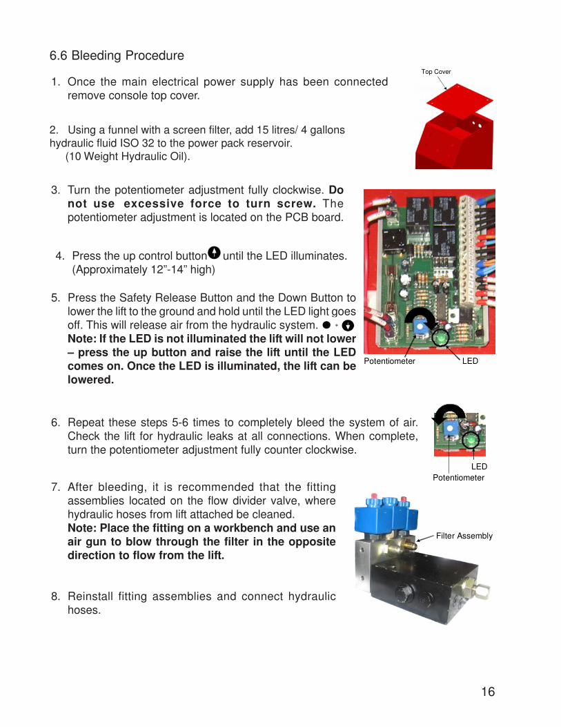
6.6 Bleeding Procedure
1. Once the main electrical power supply has been connectedremove console top cover.
7. After bleeding, it is recommended that the fittingassemblies located on the flow divider valve, wherehydraulic hoses from lift attached be cleaned.Note: Place the fitting on a workbench and use anair gun to blow through the filter in the oppositedirection to flow from the lift.
8. Reinstall fitting assemblies and connect hydraulichoses.
3. Turn the potentiometer adjustment fully clockwise. Donot use excessive force to turn screw. Thepotentiometer adjustment is located on the PCB board.
Top Cover
LEDPotentiometer
4. Press the up control button until the LED illuminates.(Approximately 12”-14” high)
5. Press the Safety Release Button and the Down Button tolower the lift to the ground and hold until the LED light goesoff. This will release air from the hydraulic system.Note: If the LED is not illuminated the lift will not lower– press the up button and raise the lift until the LEDcomes on. Once the LED is illuminated, the lift can belowered.
6. Repeat these steps 5-6 times to completely bleed the system of air.Check the lift for hydraulic leaks at all connections. When complete,turn the potentiometer adjustment fully counter clockwise.
LEDPotentiometer
Filter Assembly
+
2. Using a funnel with a screen filter, add 15 litres/ 4 gallonshydraulic fluid ISO 32 to the power pack reservoir. (10 Weight Hydraulic Oil).
17
Leveling Bolt 5/8”-UNC Hex Bolt (6-1670)
¾”-16 UNF Support Bolt
NOTICE
CORRECT LEVELING IS IMPORTANT TO ENSURE THE PROPER OPERATION OFTHE LIFT. TAKE PRECAUTIONS TO ENSURE ACCURATE LEVEL READINGS WHENPERFORMING THIS PROCEDURE.
Side-to-side leveling measurements should be taken off the baseframe, and measure-ments should be taken on each baseframe as well as between the two baseframes. Front-to-back level measurements should be taken on the runways.
6.7 Level and Support
2. Level the baseframes using the 5/8” leveling bolts provided ateach of the four (4) corners.
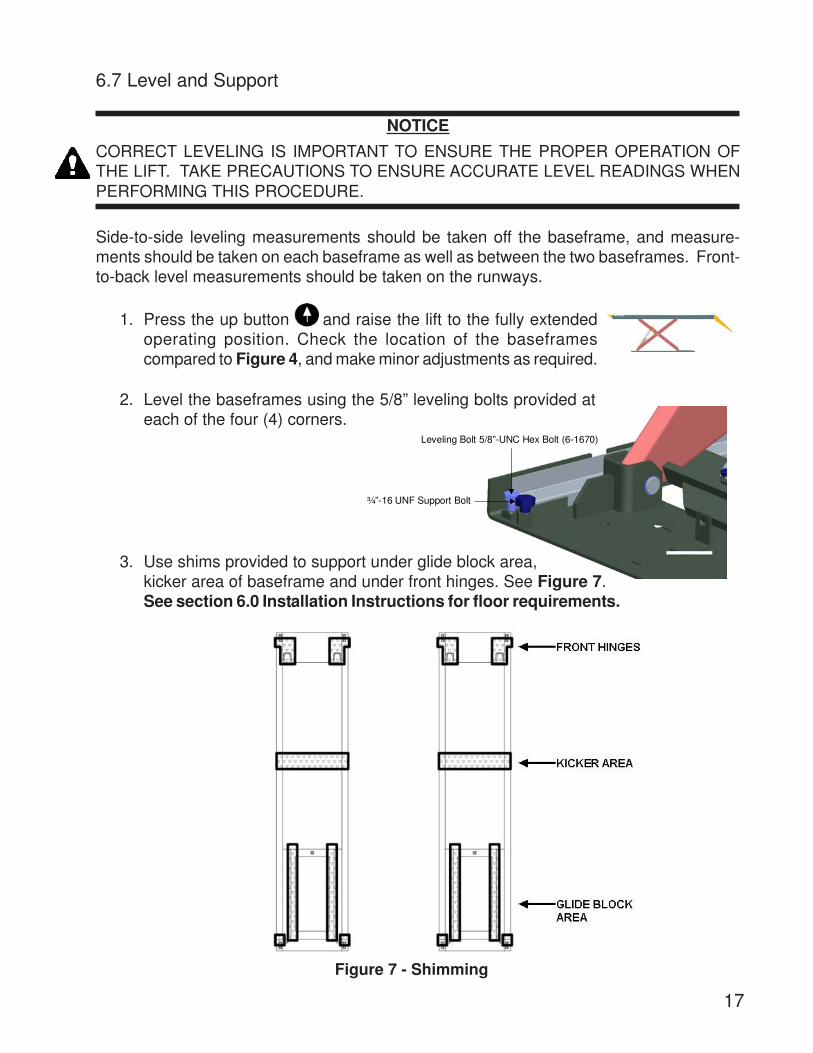
3. Use shims provided to support under glide block area,kicker area of baseframe and under front hinges. See Figure 7.See section 6.0 Installation Instructions for floor requirements.
1. Press the up button and raise the lift to the fully extendedoperating position. Check the location of the baseframescompared to Figure 4, and make minor adjustments as required.
Figure 7 - Shimming
18
LevelingBoltLocations
4. Verify that the baseframes are level side-to-side and that the runways are levelfront-to-back. The front turnplate and rear slip plate are the areas of interest. Checkthat the spacing between the runways is as desired, and that this spacing is equal atboth the front and rear of the lift. Runway
Baseframe
5. Once lift is level, back off 5/8” leveling bolts sothat the base is firmly sitting on the shims. Re-check to make sure the lift is still level and shimsare holding properly.
*Check that the diagonal measurements between opposite corners of the baseframesare equal. Lower and raise the lift and repeat these measurements.
Note: These bolts must be removed once theshims are installed under the base correctly.
6.8 Anchoring Procedure
Figure 8 - Anchoring
19
½” x 4 ½” Long Wedge Anchor bolts
Place and AnchorConsole
3. Using a hammer drill and a ½” concrete bit, drillthrough the floor at each of the six (6) anchor boltlocations on each of the base frames. Make sure thatthe 1/2” concrete drill bit is in good condition. Refer to
baseframe figure to the right.
7. Position the console in the final desired location.Refer to Figure 3. Using a hammer drill and a 1/4”concrete bit, drill and anchor the console to thefloor using the Nail in Anchors located in thehardware kit.
1. Lower the lift and measure the distance between theJackbeam rails at front and rear of the lift.
J a c k b e a m R a ils
4. Assemble the nuts and washers on the 1/2” x 4 ½”long wedge anchor bolts supplied ensuring a minimumof six threads are visible below the nut, and hammerin the anchors leaving space for shimming.
5. Use shims provided to support around anchor positionand hammer anchors until they make contact with thebaseplate.
6. Torque all anchor bolts to 40 ft- lbs (54 N.m).
9”
Baseframe
Support Bolt ¾”-16 UNF (6-3194)
Deck
NOTE: The ½” × 4 ½” long wedge anchor boltssupplied must have a maximum of 2 ¼” exposedabove the concrete.
NOTE: The wedge anchor must be a minimum of 6 1/8”away from any cracks, edges and joints
8. Check that the 3/4" support bolts on the four (4) corners of the baseframes areadjusted to ensure that the runway is level at fully collapsed position. (9 inches).
2. Raise the lift to full height and repeat the measurements, and ensure there are no differences.
9. Clean kicker area and grease kicker using a multipurpose, extreme pressure greasesuch as Dynalife L-EP, NLGI Grade 2 or equivalent. Refer to Maintanence Section10.1 for procedure.
20
1. Pour grouting under the load area of each base frame as shown in Figure 9. En-sure that grout is evenly distributed under the frame and finish the edges with a 45degree chamfer. Refer to specific grouting instructions on the package. Leave adrain area to allow any liquids to escape.
2. GROUTING MUST FULLY CURE BEFORE PROCEEDING. Do not operate the liftwhile grout is curing. Refer to instructions on the package for recommended curetimes. [Non-Shrink Grout (3000psi min. in 24hrs, 7000psi min. in 30 days)]
Figure 9 - Grouting Locations
6.9 Grouting Procedure (Optional)
21
1. Install the front Wheelstops located in the accessory box using the ½” Hex Bolts,Washers, Lockwashers, and Hex Nuts located in the hardware kit.
7.0 ACCESSORY INSTALLATION
3. Install Jackbeams with reference to the Jackbeam user manual.
2. Install the rear approach ramps using the Approach Ramp Pins located in the ac-cessory box, and the Flatwashers and Cotter Pins located in the hardware kit.
The runway stops are designed as a secondary means to restrain a vehiclefrom inadvertently rolling off the runways. Property damage and physical injuriesmay occur if this warning is not adhered to.
22
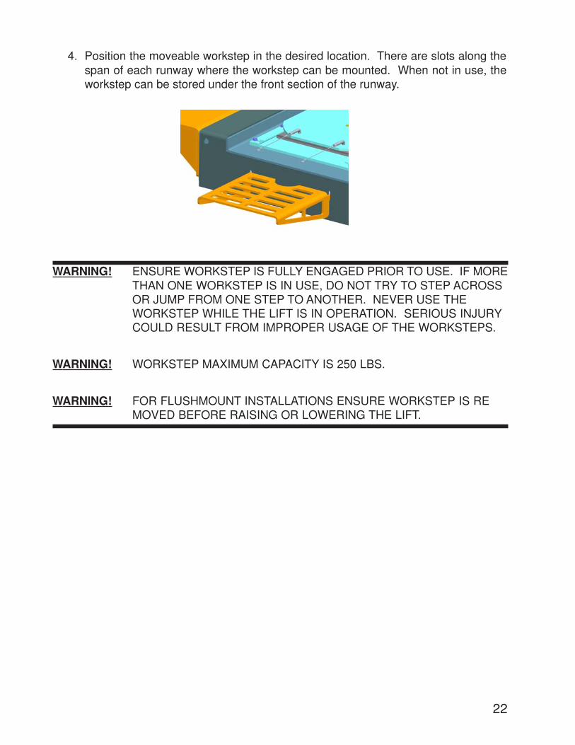
4. Position the moveable workstep in the desired location. There are slots along thespan of each runway where the workstep can be mounted. When not in use, theworkstep can be stored under the front section of the runway.
WARNING! ENSURE WORKSTEP IS FULLY ENGAGED PRIOR TO USE. IF MORETHAN ONE WORKSTEP IS IN USE, DO NOT TRY TO STEP ACROSSOR JUMP FROM ONE STEP TO ANOTHER. NEVER USE THEWORKSTEP WHILE THE LIFT IS IN OPERATION. SERIOUS INJURYCOULD RESULT FROM IMPROPER USAGE OF THE WORKSTEPS.
WARNING! WORKSTEP MAXIMUM CAPACITY IS 250 LBS.
WARNING! FOR FLUSHMOUNT INSTALLATIONS ENSURE WORKSTEP IS REMOVED BEFORE RAISING OR LOWERING THE LIFT.
23
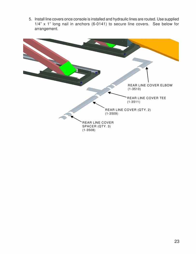
5. Install line covers once console is installed and hydraulic lines are routed. Use supplied1/4” x 1” long nail in anchors (6-0141) to secure line covers. See below forarrangement.
REAR LINE COVER SPACER (QTY. 3)(1-3508)
REAR LINE COVER (QTY. 2)(1-3509)
REAR LINE COVER TEE(1-3511)
REAR LINE COVER ELBOW(1-3510)
24
8.0 FINAL PROCEDURES
8.1 Check of Assembled Lift
1. Final dimension check after anchoring. ____
2. Check for air and hydraulic leaks. ____
3. Re-check level of decks, front to rear , side to side. ____
4. Check all fasteners, tighten if necessary. ____
5. Operate lift to full stroke then lower to ground while checking ____for proper functionality.
6. Ensure Customer Care Kit is complete and given to operator. ____
a. Operation Manual ____
b. ANSI / ALI Lift It Right Manual ____
c. ANSI / ALI Safety Tip Card ____
d. ANSI / ALI ALIS Safety Requirements for Installation ____ and Service of Automotive Lifts
e. ANSI / ALI Quick Reference Guide ____
7. Train end user on operation of lift. ____
25
8.2 Operation Test With Vehicle
1. Lower lift to the ground. (Make sure Green Light is OFF) ____
2. Drive vehicle on to lift. ____
3. Raise lift to and lower onto 3-4 lock positions during full rise to ensureall locks are working correctly. ____
4. Check lowering speed and smooth decent rate. ____
5. Lower lift to the ground and drive vehicle off lift. ____
If any problems occur during the final checkout or operation of the lift please contact customerservice at 1-800-225-5786
26
1. If the lift is equipped with sliding Jack Beam(s), be sure that the Beam(s) are posi-tioned at the front or mid travel of the lift, fully down, and with the risers removed andstored. Never store Jack Beams at the rear of the lift.
2. Ensure that the lift is fully lowered before attempting to load or unload a vehicle.3. Ensure that locking pins are in the front turnplates and rear slip plates before driving a
vehicle onto the lift.4. Position the vehicle on the lift ensuring the resulting load on the deck is distributed as
evenly as possible. Under no circumstances should a vehicle be lifted if the weightdistribution is unbalanced by more than 10% on either side.NOTE: THE VEHICLE IS POSITIONED CORRECTLY WHEN THE DISTANCE FROMTHE CENTER OF THE TIRES TO THE INSIDE EDGE OF THE RUNWAYS IS EQUALON BOTH RUNWAYS, FOR BOTH THE FRONT AND REAR TIRES.
6. Chock the vehicle using the wheel chocks provided.7. Check that there are no obstructions above the lift that could damage the lift or ve-
hicles.8. Raise the lift by pressing the up button on the control console. Raise the lift until the
green light is illuminated. (The lift can only be lowered if the green light is on).9. Lower the lift onto a mechanical safety lock by pressing the down button. Continue to
hold the down button until the green light goes off. (Approx. 3-10 sec).
WARNING: NEVER WORK UNDER A VEHICLE OR THE LIFT UNLESS IT IS POSITIONEDON BOTH MECHANICAL SAFETIES!
1. Lower the vehicle from the Jack beams and remove lift pads and store. If removing thevehicle from the lift, slide Jack Beams to their appropriate position, at the front or midsection of the lift. Check that there are no other obstructions under the lift or vehicle.
2. Raise the lift by pressing the up button until both runways are clear of their mechanicalsafety locks.
3. Press the air safety release button to release the mechanical safeties.4. While holding the air safety release button, press the down button and lower the lift to
the completely collapsed position.5. Remove wheel chocks and ensure that locking pins are in the front turnplates and rear
slip plates before driving a vehicle off the lift.6. Be certain that the lift is completely lowered before removing the vehicle from the lift.
ATTENTION: THE OPERATOR MUST ALWAYS KEEP THEIR ATTENTION ON THE OP-ERATION OF THE LIFT WHILE RAISING OR LOWERING. IF AN OBSTRUCTION IS SEEN,RELEASE BOTH THE AIR SAFETY RELEASE BUTTON AND THE DOWN BUTTON TOSTOP THE LIFT.
9.0 LIFT OPERATION9.1 Raising the Lift
9.2 Lowering the Lift
NOTE: The lift can only be lowered if the green light is on. If the light is not on, raise the liftuntil the light turns on. If the lift is at its maximum lifting height, a change in tonemay be noticed while raising the lift (This change is the pump working at max reliefpressure). Only press the up button until the green light comes on.
27
10.0 RECOMMENDED MAINTENANCE
The following maintenance schedule is recommended for ensuring the operation of the lift. Arecord of maintenance performed should be maintained and any items that resulted in addi-tional service should be noted.
NOTE: FAILURE TO FOLLOW RECOMMENDATION MAY AFFECT WARRANTY OF LIFT
10.1 Kicker Greasing Procedure1. Clean both the kicker and the kicker area on the baseframe.2. Grease kicker using a multipurpose, extreme pressure grease such as Dynalife L-EP, NLGI Grade 2 or equivalent.
3. Locations to be cleaned and greased are as shown below:
Clean surfaces
Grease across span of glide block
Schedule Maintenance RequiredCheck that the upper and lower glide tracks are clean and free of debris. This area should be checked before raising or lowering the lift.
Inspect the operation of the lift by raising and lowering the lift fully.
Check for the proper engagement and release of mechanical safety locks. If bolts are removed for maintenance re-apply LOCTITE #242 before re-assembly
Check hydraulic lines for leaks and fraying. Frayed hoses must be replaced immediately.
WeeklyCheck the fluid level in the reservoir with the lift fully lowered. Topup reservoir with ISO 32 (10 weight) hydraulic oil as needed.
Check anchor bolts for tightness. Torque to 40 ft-lbs if needed.
Inspect the electrical and mechanical operation of all switches.
Clean kicker plate and re-grease. See Section 10.1 for procedure and grease requirements. (See Figure 7 for kicker area).
Inspect runway stop fasteners monthly.
5 YearChange the hydraulic fluid every five years. Use only ISO 32 (10 weight) hydraulic oil.
Daily
Monthly
28
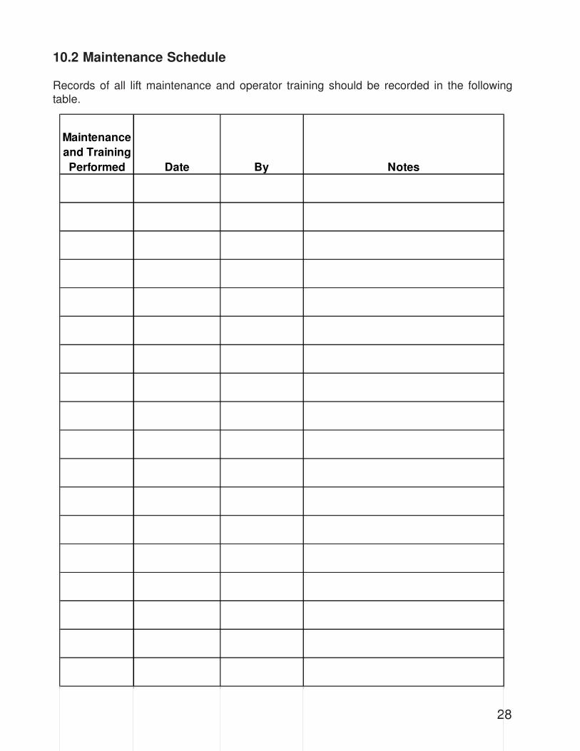
10.2 Maintenance Schedule
Maintenance and Training Performed Date By Notes
Records of all lift maintenance and operator training should be recorded in the followingtable.
29
11.0 TROUBLE SHOOTING
P ROB LE M RE A S ON S OLUTIONB ad fuse o r c ircuit breake r. Replace fuse or reset b reake r.Inco rrect vo ltage to m otor. P rovide p rope r vo ltage to mo to r.Inco rrect wiring . Have ce rti fied e lectric ian check M oto r switch is ma lfunc tioning Replace m otor switch.M oto r burned out Replace m otor.Low o il leve l F ill reservoir with p rope r
hyd raulic o il.W rong ro tation C heck for o il flow & reve rse
e lectrica l leadsD irt in hydraulic lines C heck power to hydraulic lines
*S ecure vehicle on lift, and clean hyd raulic lines.
No power to so lenoids C heck power to so lenoidsL ift no t ra ised high enough for d isengagement
P ress Up button fo r longe r period of time .
A ir not supplied to a ir cylinder C heck if supp ly line has a ir.A ir cylinder ma lfunctioning Replace a ir cylinde r.
L ift goes up unleve l. F low d ivider de fective Reverse hydraulic connections
B lockage in hyd raulic hoseRemove & inspect flow through line
Ho les a re to la rge. Re loca te lift using p rope r d rills ize .
Inco rrect concre te floor spec ifica tion. (Thickness and S treng th)
C oncrete should be replaced by an approp ria te concre te pad . (C onsult P roduct M anufac ture r / S upplie r fo r further de ta ils)
No ise S queeking no ise during firs t few inches o f rise
C lean kicke r and area . Grease kicker (see S ection 10.1 fo r Greasing P rocedure)