17
Rev: B Revision Date: 04/14/2014 Page 1 of 17 MAN – FD600CAM-3 FD600CAM-3 Installation and Operation Manual Glareshield Camera TECHNICAL SUPPORT 470-239-7421, or www.FlightDisplay.com
| Date post: | 23-Apr-2018 |
| Category: |
Documents |
| Upload: | phungtuong |
| View: | 219 times |
| Download: | 3 times |
Rev: B
Revision Date: 04/14/2014
Page 1 of 17 MAN – FD600CAM-3
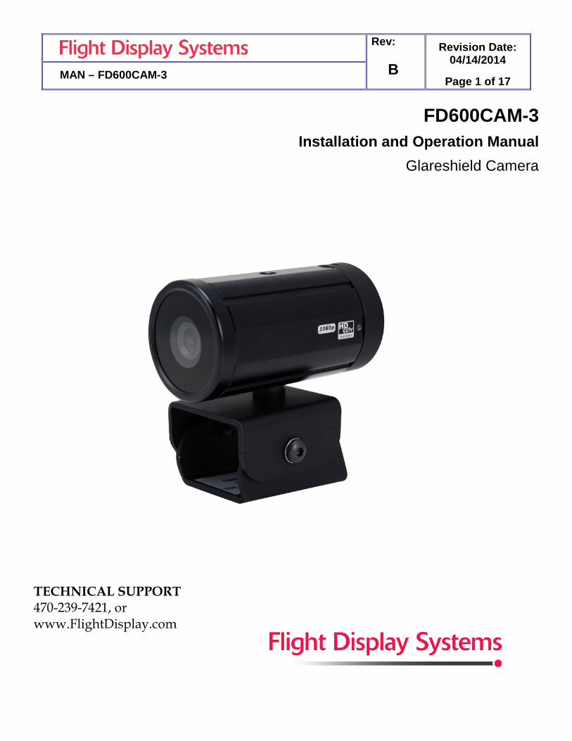
FD600CAM-3 Installation and Operation Manual
Glareshield Camera
TECHNICAL SUPPORT 470-239-7421, or www.FlightDisplay.com

Rev: B
Revision Date: 04/14/2014
Page 2 of 17 MAN – FD600CAM-3
FD600CAM-3
Glareshield Camera
© 2014 Flight Display Systems. All Rights Reserved.
Flight Display Systems 6435 Shiloh Road Suite D Alpharetta, GA 30005 678-867-6717 Phone 678-867-6742 Fax [email protected] www.FlightDisplay.com
For the most current copy of all product manuals, please visit our website at www.FlightDisplay.com
For additional support, please visit our Frequently Asked Questions section located on our web site Support Center at http://support.FlightDisplay.com.

Rev: B
Revision Date: 04/14/2014
Page 3 of 17 MAN – FD600CAM-3
Table of Contents General Information ...................................................................................................................4
Front View ..................................................................................................................................4
Specifications .............................................................................................................................5
Installation Instructions ..........................................................................................................5
Power ...........................................................................................................................................5
Wiring Suggestions ..................................................................................................................6
Video Wiring..............................................................................................................................6
Power & Ground Wiring .........................................................................................................6
Power/Video ...............................................................................................................................7
RS485 ...........................................................................................................................................8
RS485 Port Configurations ......................................................................................................8
Functions.....................................................................................................................................9
OSD Menu............................................................................................................................ 9-12
Technical Drawing..................................................................................................................13
Troubleshooting ......................................................................................................................14
Video Noise ..............................................................................................................................14
VGA Shadowing .....................................................................................................................14
Snow or Sweeping Lines .......................................................................................................14
No Power to Monitor, or No Video Input ..........................................................................14
Color Distortion ......................................................................................................................14
Technical Support ...................................................................................................................15
Instructions for Continued Airworthiness ........................................................................15
Warranty ...................................................................................................................................16
Log of Revisions ......................................................................................................................16

Rev: B
Revision Date: 04/14/2014
Page 4 of 17 MAN – FD600CAM-3
General Information
The FD600CAM-3 is a Glareshield Camera. This small color camera, when mounted in the cockpit, will provide passengers with an opportunity to observe taxi, take-off, and landing, adding a whole new dimension to the In-Flight Entertainment experience!
Front View
Rev: B
Revision Date: 04/14/2014
Page 5 of 17 MAN – FD600CAM-3
Specifications
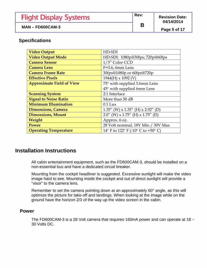
Video Output HD-SDI Video Output Mode HD-SDI: 1080p@30fps; 720p@60fps Camera Sensor 1/3” Color CCD Camera Lens F=3.6, 6mm Lens Camera Frame Rate 30fps@1080p or 60fps@720p Effective Pixels 1944(H) x 1092 (V) Approximate Field of View 75° with supplied 3.6mm Lens
45° with supplied 6mm Lens Scanning System 2:1 Interlace Signal to Noise Ratio More than 50 dB Minimum Illumination 0.1 Lux Dimensions, Camera 1.35” (W) x 1.35” (H) x 2.92” (D) Dimensions, Mount 2.0” (W) x 1.75” (H) x 1.75” (D) Weight Approx. 6 oz. Power 28 Volt nominal, 18V Min / 30V Max Operating Temperature 14° F to 122° F (-10° C to +50° C)
Installation Instructions
All cabin entertainment equipment, such as the FD600CAM-3, should be installed on a non-essential bus and have a dedicated circuit breaker.
Mounting from the cockpit headliner is suggested. Excessive sunlight will make the video image hard to see. Mounting inside the cockpit and out of direct sunlight will provide a “visor” to the camera lens.
Remember to set the camera pointing down at an approximately 60° angle, as this will optimize the picture for take-off and landings. When looking at the image while on the ground have the horizon 2/3 of the way up the video screen in the cabin.
Power The FD600CAM-3 is a 28 Volt camera that requires 160mA power and can operate at 18 – 30 Volts DC.

Rev: B
Revision Date: 04/14/2014
Page 6 of 17 MAN – FD600CAM-3
Wiring Suggestions
Avoid routing video wiring parallel to:
• AC wiring
• Strobe wiring
• DC motor supply cables
• Inverter cabling
• Or any other potential noise source.
Video Wiring Recommended cable is PIC 75 Ohm Coax, P/N V76261. This is a lightweight, flexible, and low signal loss cable which meets FAA flammability requirements of FAR 23.1359(d), FAR 25.853(a) and FAR 25.869(a)(4).
Similar coaxial cable can be used from other vendors, as well. Some aircraft are prone to AC noise. Video isolation transformers are effective in solving many kinds of noise problems. Allen Avionics part number: HD-VIT-75 (http://allenavionics.com (516) 248-8080).
Power and Ground Wiring 22 AWG wire is recommended for Power and Ground applications.

Rev: B
Revision Date: 04/14/2014
Page 7 of 17 MAN – FD600CAM-3
Power/Video
Standard Density DB-9 Receptacle (supplied)
Connector P/N: M24308/2-281 or Equivalent Crimp Contacts P/N: M39029/63-368 or Equivalent
Pin Number
FD600CAM-3 Description
1 28 VDC Input 2 28 VDC Return 3 RS-485 B 4 RS-485 A 5 N/C 6 N/C 7 N/C 8 N/C 9 N/C

Rev: B
Revision Date: 04/14/2014
Page 8 of 17 MAN – FD600CAM-3
RS485 Control
The FD600CAM-3 can be setup and configured through the OSD menu. This menu can be accessed and controlled via RS485 commands. RS485 Port Configuration: The RS-485 port at default is standard 9600 baud, no parity, 8 data bits, 1 stop bit, and no flow control. It is standard two wires half duplex. The commands are all ASCII human readable. Prefix: One Character. All RS-485 remote commands must start with the “!” character. Device ID: Three Characters. “CAM” identifies all commands directed to the FD600CAM-3. Commands: !CAM,En – Button East !CAM,Wn – Button West !CAM,Sn – Button South !CAM,Nn – Button North !CAM,Pn – Button Press (n = single ASCII char 0 to 9.) • 0 = Button Pulse Time 0.25 Seconds • 1 = Button Pulse Time 0.50 Seconds • 2 = Button Pulse Time 0.75 Seconds • 3 = Button Pulse Time 1.00 Seconds • 4 = Button Pulse Time 1.25 Seconds • 5 = Button Pulse Time 1.50 Seconds • 6 = Button Pulse Time 1.75 Seconds • 7 = Button Pulse Time 2.00 Seconds • 8 = Button Pulse Time 2.25 Seconds • 9 = Button Pulse Time 2.50 Seconds Note: Buttons – North, South, East and West auto repeat Termination: One Character; ASCII CR. Each command must end with Carriage Return<CR>.

Rev: B
Revision Date: 04/14/2014
Page 9 of 17 MAN – FD600CAM-3
OSD Menu Structure
Main Sub Menu Sub Menu
EXPOSURE
BRIGHTNESS 0 - 20 SHUTTER MODE
AUTO.MANUAL
SHUTTER SPEED
1/30(25), 1/60(50), 1/120(100), 1/250, 1/700, 1/1K, 1/1.6K, 1/2.5K, 1/5K, 1/7K, 1/10K, 1/30K.*() is for power-frequency 50Hz.
DSS OFF, X2, X3, X4. AGC MAX 0-23dB INITIAL BACK,DEFAULT RETURN BACK,EXIT
WHITE BALANCE
WB MODE AUTO, PUSH LOCK, MANUAL, AUTO EXT CHROMA 0-20 KELVIN 0-20 RED GAIN 0-20 BLUE GAIN 0-20 PUSH AUTO ON,OFF INITIAL BACK,DEFAULT RETURN BACK,EXIT
WDR/BLC
MODE ON,OFF WDR LEVEL 0-4 BLC OSD ON,OFF BLC X-POS 0 - 20 BLC Y-POS 0 - 20 BLC X-SIZE 0 - 20 BLC Y-SIZE 0 - 20 INITIAL BACK,DEFAULT RETURN BACK,EXIT
DAY & NIGHT
MODE COLOR, B/W, AUTO DWELL TIME 3s AGC THRS 0-10 MARGIN 0-10 INITIAL BACK,DEFAULT RETURN BACK,EXIT
IMAGE
SHARPNESS 0-10 MIRROR ON,OFF FLIP OFF, H FLIP, V FLIP, HV FLIP DZOOM 0-20X HLMASK
ON,OFF
HLMASK LEVEL: 0-20
HLMASK COLOR: Black, White, Yellow, Cyan, Green, Magenta, Red, Blue
D-WDR 0-4 DNR LOW, MIDDLE,NIGH INITIAL BACK/DEFAULT

Rev: B
Revision Date: 04/14/2014
Page 10 of 17 MAN – FD600CAM-3
Main Sub Menu Sub Menu
SPECIAL
CAM TITLE 0 - 20 LANGUAGE ENGLISH, RUSSIAN, SPANISH, GERMAN, FRENCH, PORTUGUESE
PRIVACY ON, OFF
ZONE NO 0-23 MASK MODE ON,OFF X-POSITION 0-60 Y-POSITION 0-40 X-SIZE 0-40 Y-SIZE 0-40 INITIAL BACK,DEFAULT RETURN BACK,EXIT
MOTION
RESOLUTION 1-10 SENSITIVITY 1-10 WINDOW USE ON, OFF WINDOW TONE
1-10
X-POSITION 0-60 Y-POSITION 0-40 X-SIZE 0-40 Y-SIZE 0-40 INITIAL BACK,DEFAULT RETURN BACK,EXIT
DISPLAY
CAM TITLE ON, OFF MOTION ON, OFF DZOOM ON, OFF INITIAL BACK,DEFAULT RETURN BACK,EXIT
SYSTEM
SHADING DET ON, OFF DEFECT DET ON, OFF DOUT FORMAT
1080P / 720P
DOUT FPS 30, 60 CVBS PAL, NTSC APPLY

Rev: B
Revision Date: 04/14/2014
Page 11 of 17 MAN – FD600CAM-3
Function Description SETUP - EXPOSURE: Go sub menu for camera exposure control. - WHITE ALANCE: Go sub menu for camera white balance control. - WDR / BLC: Go sub menu for camera WDR or BLC action. - DAY&NIGHT: Control day and night settings - IMAGE: Go sub menu for adjust image functions. - SPECIAL: Go sub menu for special feature control. - FACTORY DEFAULT: Reset all settings back to factory default - EXIT EXPOSURE - BRIGHTNESS: Adjust image brightness value. - SHUTTER MODE: Select shutter speed control type. - SHUTTER SPEED: Enable user to set up the Shutter Speed - DSS: Adjust digital slow shutter control level. - AGC: Adjust max gain level for brightness control. WHITE BALANCE - WB MODE: Select white balance control mode.
• AUTO: Enable user to trace the White Balance automatically in the range of 2,300K~10,000K. • PUSH LOCK: Enable user to fix the White Balance according to the color temperature in environment. • MANUAL: Enable user to sets the White Balance according to the circumstance • AUTO EXT: Extended auto mode for special illumination.
- CHROMA: Enable user to set the Color Gain(0~20steps). - KELVIN: In the MANUAL setting of WB MODE, enable user to set the color
temperature range. - RED GAIN: In the MANUAL setting of WB MODE, enable user to set the RED
GAIN. - BLUE GAIN: In the MANUAL setting of WB MODE, enable user to set the BLUE
GAIN. - PUSH AUTO: In the PUSH LOCK setting of WB MODE, enable user to fix the
White Balance in camera setting. - INITIAL: Enable user to reset the WHITE BALANCE menu setting.

Rev: B
Revision Date: 04/14/2014
Page 12 of 17 MAN – FD600CAM-3
WDR/BLC - MODE: Select WDR for BLC mode. - WDR LEVEL: Enable user to adjust level of WDR(Wide Dynamic Range). - BLC OSD: Enable user to set up screen output of selected BLC zone. - BLC X-POSITION: Enable user to set up screen output of selected BLC zone. - BLC Y-POSITION: Enable user to set up Horizontal start position. - BLC X-SIZE: Enable user to set up Vertical size. - BLC Y-SIZE: Enable user to set up Horizontal size. - INITIAL: Enable user to initialize the BLC setting. DAY&NIGHT - DAY&NIGHT MODE: Conversion of output image COLOR / BW depending on exterior
environment. • COLOR: Enable user to fit the output image in color. • B/W: Enable user to fit the output image in B/W. • 3 AUTO: Enable user to convert to COLOR/BW automatically by
photocell - DWELL TIME: In D&N MODE AUTO, enable user to set to delay time for
changing COLOR/BW - INITIAL: Enable user to initialize the setting in DAY&NIGHT menu. IMAGE - SHARPNESS: Enable user to control the image sharpness. - MIRROR: Enable user to mirror flip the image. - FLIP: Sets the Vertical flip for the display output. - DZOOM(Digital Zoom): Max. 20x Digital Zoom. - HLMASK: Suppresses or masks strong light sources.
• HLMASK LEVEL: Enable user to set HLMASK Level. • HLMASK COLOR: Set the HLMASK color
- D-WDR: In this mode, the brightness of a single image is compensated using the gamma curve.
- DNR: This function reduces noise. - INITIAL: Enable user to initialize the setting on IMAGE menu. SPECIAL - CAM TITLE: Enable user to choose any word in screen. (Maximum 10 letter is
available) • A letter Choice from the screen using Menu key. • Enable user to move to next menu using LEFT, RIGHT KEY in LOCATION.

Rev: B
Revision Date: 04/14/2014
Page 13 of 17 MAN – FD600CAM-3
• By using UP, DOWN, LEFT, RIGHT KEY, enable user to choose any letters in
LOCATION and then get back to previous step. • Enable user to finish words choice and position by using LEFT, RIGHT KEY in
RETURN. - LANGUAGE: Enable user to set up an OSD language. - PRIVACY: Enables privacy function.
• ZONE NO: Enable user to set up a position from 0 to 29 area. • MASK MODE: Enable user to set up screen output of chosen position. • X-POSITION: Mask Horizontal start position. • Y-POSITION: Mask Vertical start position. • X-SIZE: Mask Horizontal width. • Y-SIZE: Mask Vertical height. • COLOR: Set the mask color. • TRANSPARENCY: Set the transparency of the mask. • INITIAL: Enable user to initialize setting of PRIVACY MENU.
- MOTION: Motion detection function. • RESOLUTION: Enable user to set up resolution • SENSITIVITY: Enable user to set up sensitivity. • WINDOW USE: Enable user to select to motion area. • WINDOW TONE: Enable user to area window tone. • X-POSITION: Window Horizontal start position. • Y-POSITION: Window Vertical start position. • X-SIZE: Window Horizontal width. • Y-SIZE: Window Vertical height. • INITIAL: Enable user to initialize setting of MOTION DETECT.
- DISPLAY: Enable user to set up a screen marking CAM TITLE, MOTION, DZOOM. • CAM TITLE: Enable user to set up output in fixed CAM TITLE. • MOTION: Enable user to set up output of MOTION on the screen as MOTION ON
setting. • DZOOM: Enable user to set up output DZOOM ratio. • INITIAL: Enable user to initialize of DISPLAY menu.
- SYSTEM: Go sub menu for system control & information. • DEFECT DET: White pixel detection and compensation function. • DOUT FORMAT: Enable user to set up digital output format (720p, 1080p). • DOUT FPS: Enable user to set up digital output frame rate. • 4.FREQ: Enable user to set up power-frequency(50Hz, 60Hz). • CVBS: Enable user to set up CVBS type NTSC or PAL. • APPLY: Enable user to setting of SYSTEM.
FACTORY DEFAULT : Enable user to reset all of the status as the factory default.
Rev: B
Revision Date: 04/14/2014
Page 14 of 17 MAN – FD600CAM-3
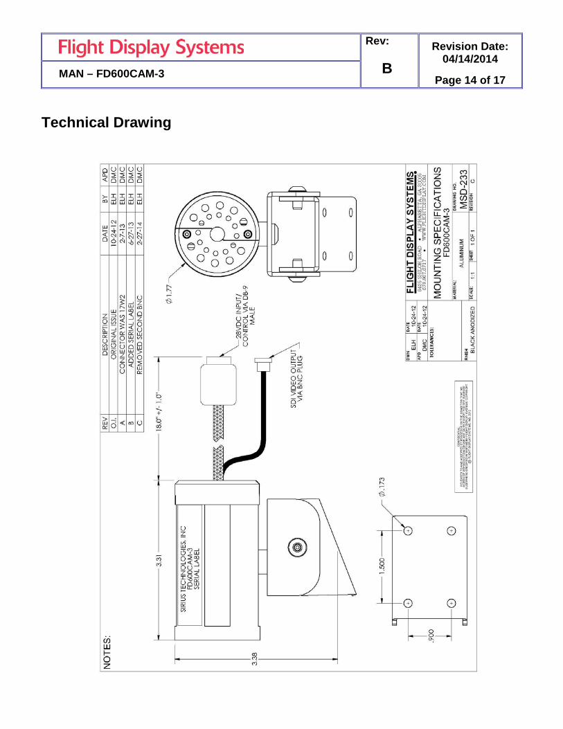
Technical Drawing
Rev: B
Revision Date: 04/14/2014
Page 15 of 17 MAN – FD600CAM-3
Troubleshooting
Video Noise Check for an incorrect ground in the installation wiring. See specific examples of video noise below, or visit http://flightdisplay.com/Grounding.pdf
VGA Shadowing Most of shadowing problems are due to shielding on the wire. Locate the point where all of the shields are connected. Cut away the shields, one at a time, while viewing the display on the screen to observe which shield is causing the noise. Cutting away one shield at a time will allow you to focus and isolate the video noise issue.
• Twisted pair wiring is prone to video noise. ECS VGA Wire
(Detailed under “Video Wiring Suggestions”) is recommended.
Snow or Sweeping Lines Lines that slowly sweep up and down are a result of AC noise. This AC noise can be generated by a power cart on the aircraft. Take the power cart off of the aircraft. Be careful of inverter wiring, which can also cause noise. Stand off the wires, if necessary.
If snow or sweeping lines persist, it is possible that the ground is at an incorrect point in the aircraft. Try moving the ground to another location.
No power to Monitor, or No video Input • Verify correct wiring. Check the base receptacle connectors for possibly damaged pins.
• Check that the video source is:
1. Powered on,
2. In Play mode, and
3. Displaying video.
Color Distortion • Adjust brightness and contrast settings using the buttons on the monitor.
Rev: B
Revision Date: 04/14/2014
Page 16 of 17 MAN – FD600CAM-3
Technical Support
Should you have any questions concerning this product or other Flight Display Systems products, please contact our Product Support representatives at (470) 239-7421.
Flight Display Systems 6435 Shiloh Road Suite D Alpharetta, GA 30005 Phone: 678-867-6717 Fax: 678-867-6742 Email: [email protected]
For further product information, technical data and sample wiring diagrams, please click on the Dealers section of our web site at www.FlightDisplay.com
Instructions for Continued Airworthiness
The FD600CAM-3 is designed not to require regular general maintenance.

Rev: B
Revision Date: 04/14/2014
Page 17 of 17 MAN – FD600CAM-3
Warranty Information
Flight Display Systems warrants all our products against material or manufacturing defects. We provide a two-year warranty to all Corporate Aviation Customers, a one-year warranty to Government/Special Missions and a one-year warranty on all headset equipment. Our warranty begins on the date of installation. *The warranty registration card must be returned upon installation in order to validate the warranty. Any warranty registration not returned during this time period will default to the date of purchase as the warranty start date.
If product support is required, please call our Technical Support team at 470-239-7421 to obtain assistance. If the return of the unit to the factory is required, an RMA number will be issued at that time. Flight Display Systems will, upon receipt of the failed hardware, remanufacture or replace the unit at our discretion.
Flight Display Systems will pay Ground Return Shipping charges for warranted items returned to the customer. Charges for express shipment will be the responsibility of the sender.
This warranty is not transferable. Any implied warranties expire at the expiration date of this warranty. We shall not be liable for incidental or consequential damages.
This warranty does not cover a defect or failure that has resulted from improper or unreasonable installation, use or maintenance, as determined by Flight Display Systems. This warranty is void if there is any attempt to disassemble or open this product without factory authorization.
Any labor charges associated with the removal of product or related troubleshooting by a firm other than Flight Display Systems will not be covered.
Revision Logs
Rev Date Page Description
A 03/05/2014 All Initial Release
B 04/14/2014 8 Added RS485 Commands


