Table of Contents 1 GENERAL INFORMATION ...................................................................................................................... 1-1
2.8.1 DC Input Connector, J6 .................................................................................................................. 2-7 2.8.2 Audio Level Adjustment Potentiometers and Input Test Point ........................................................ 2-8 2.8.3 Connection to Radio or Other Four-Wire Device (J7) .................................................................... 2-8 2.8.4 Network Connection, J3 .................................................................................................................. 2-8 2.8.5 Serial Port Connection, J4 .............................................................................................................. 2-9 2.8.6 Connecting Equipment and Computers to an NXU-2A ................................................................... 2-9
3.1 GENERAL .............................................................................................................................................. 3-1 3.2 CONFIGURATION DETAILS .................................................................................................................... 3-1 3.3 SERIAL PORT CONFIGURATION ............................................................................................................. 3-1
3.3.1 Configuration Using an RS-232 Terminal Program ....................................................................... 3-2 3.3.2 Command Summary ........................................................................................................................ 3-4 3.3.3 Setting Unit IP Address ................................................................................................................... 3-5 3.3.4 Setting Unit Subnet Mask and Gateway Address ............................................................................ 3-5 3.3.5 Using DHCP to Assign IP Parameters ........................................................................................... 3-5 3.3.6 Setting VoIP Port (Optional) ........................................................................................................... 3-5 3.3.7 Client/Server Selection .................................................................................................................... 3-6 3.3.8 COR and VOX Settings ................................................................................................................... 3-6 3.3.9 Duplex Setting ................................................................................................................................. 3-6 3.3.10 VOX Hang Time .............................................................................................................................. 3-7 3.3.11 COR Inhibit Time ............................................................................................................................ 3-7 3.3.12 Serial Port Settings ......................................................................................................................... 3-7 3.3.13 Voice Compression Settings ............................................................................................................ 3-8 3.3.14 Security Settings .............................................................................................................................. 3-8 3.3.15 Ethernet MAC Address .................................................................................................................... 3-8 3.3.16 Command Port ................................................................................................................................ 3-9 3.3.17 Input Level Boost +20db ................................................................................................................. 3-9 3.3.18 TX Delay ......................................................................................................................................... 3-9 3.3.19 RX Delay ......................................................................................................................................... 3-9
3.5.1 Store Setup Changes with SAVE Command .................................................................................. 3-12 3.5.2 NXU-2A Configuration Using the NXU-2A Setup Utility .............................................................. 3-12
4.1 GENERAL .............................................................................................................................................. 4-1 4.2 FRONT PANEL INDICATORS ................................................................................................................... 4-1
4.2.1 Power LED ...................................................................................................................................... 4-1 4.2.2 Link Active LED .............................................................................................................................. 4-1 4.2.3 Channel Active LED ........................................................................................................................ 4-1 4.2.4 Audio Input LED.............................................................................................................................. 4-1
4.4.1 Operation at Power-Up ................................................................................................................... 4-2 4.4.2 Input/Output Level Adjustments ...................................................................................................... 4-2 4.4.3 COR Input Description .................................................................................................................... 4-2 4.4.4 RS-232 Serial Data .......................................................................................................................... 4-2 4.4.5 Auxiliary I/O .................................................................................................................................... 4-3
4.5 CONTROLLING CONNECTIONS ............................................................................................................... 4-3 4.5.1 Serial or Telnet Control ................................................................................................................... 4-3 4.5.2 Web Browser Control ...................................................................................................................... 4-4
4.6 SECURITY .............................................................................................................................................. 4-5 4.6.1 Password Setting ............................................................................................................................. 4-5 4.6.2 Web Access with Password Protection ............................................................................................ 4-6
6.1 GENERAL .............................................................................................................................................. 6-1
7 THEORY OF OPERATION ........................................................................................................................ 7-1
8 INDEX ............................................................................................................................................................ 8-1
Interface Type 10/100BASE-T Ethernet, 10 or 100 Mbps; RJ-45 Connector.
Protocols Audio and status-UDP, RS-232- TCP.
Audio Vocoder Selectable, 13, 16, 24, 32, or 64 Kbps data rate.
General/Environmental
Programming/Configuration Web, Telnet, or RS-232 Interface.
Front Panel Power, Link Active, Channel Active, and Audio Level LEDs.
Rear Panel Audio/Data (DB15 Female), Serial, Network, and Power Connectors.
Input Power (12 VDC Nom) +11 to +15 VDC @ 0.5A max. Wall-cube supplied operates on 100-240 VAC.
Power Connector Coaxial Jack, 2.5 mm ID, 5 to 5.5 mm OD; Center Pin Positive; Reverse
Polarity Protected.
Size and Weight 1.4” H x 8”W x 6.8”D (3.55 x 20.3 x 17.3 cm). 1.1 lbs. (0.5kg).
Temperature Operating: -20 to +60 degrees C. Storage: -40 to +85 degrees C.
Humidity Up to 95% @ 55 degrees C.
Regulatory Compliance
FCC part 15
CE Emissions, Immunity and Safety for Europe
NXU-2A Operations Manual
Interoperability Now! 1-5
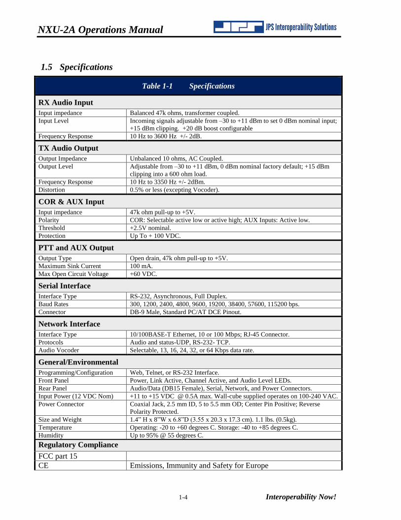
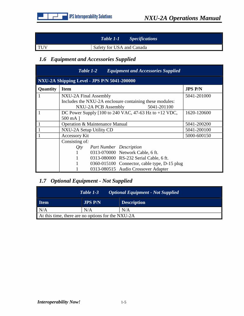
Table 1-1 Specifications
TUV Safety for USA and Canada
1.6 Equipment and Accessories Supplied
Table 1-2 Equipment and Accessories Supplied
NXU-2A Shipping Level - JPS P/N 5041-200000
Quantity Item JPS P/N
1 NXU-2A Final Assembly
Includes the NXU-2A enclosure containing these modules:
NXU-2A PCB Assembly 5041-201100
5041-201000
1 DC Power Supply [100 to 240 VAC, 47-63 Hz to +12 VDC,
500 mA ]
1620-120600
1 Operation & Maintenance Manual 5041-200200
1 NXU-2A Setup Utility CD 5041-200100
1 Accessory Kit 5000-600150
Consisting of:
Qty Part Number Description
1 0313-070000 Network Cable, 6 ft.
1 0313-080000 RS-232 Serial Cable, 6 ft.
1 0360-015100 Connector, cable type, D-15 plug
1 0313-080515 Audio Crossover Adapter
1.7 Optional Equipment - Not Supplied
Table 1-3 Optional Equipment - Not Supplied
Item JPS P/N Description
N/A N/A N/A
At this time, there are no options for the NXU-2A
NXU-2A Operations Manual
1-6 Interoperability Now!
This Page Left Intentionally Blank.
2-1
2 Installation
2.1 General
This section provides the instructions for unpacking, inspection, installation and set-up. Also
included are directions for reshipment of damaged parts or equipment.
2.2 Unpacking and Inspection
After unpacking the unit, retain the carton and packing materials until the contents have been
inspected and checked against the packing list. If there is a shortage or any evidence of
damage, do not attempt to use the equipment. Contact the carrier and file a shipment damage
claim. A full report of the damage should also be reported to the JPS Customer Service
Department. The following information should be included in the report:
Order Number
Equipment Model and Serial Numbers
Shipping Agency
Date(s) of Shipment
The JPS Customer Service Department can be reached by phone at (919) 790-1011, by fax at
(919) 790-1456. Upon receipt of this information, JPS will arrange for repair or replacement of
the equipment.
2.3 Reshipment of Equipment
If it is necessary to return the equipment to the manufacturer, a Returned Material
Authorization (RMA) number must first be obtained from JPS. This number must be noted on
the outside of the packing carton and on all accompanying documents. When packing the unit
for reshipment, it is best to use the original packaging for the unit; if this is not possible, make
sure that adequate packing material is used to prevent excessive shocks during transport and
handling.
Shipment should be made prepaid consigned to:
JPS Interoperability Solutions
Customer Service Department
5800 Departure Drive
Raleigh, North Carolina 27616
USA
NXU-2A Operations Manual
2-2 Interoperability Now!
Plainly, mark with indelible ink all mailing documents as follows:
GOODS RETURNED FOR REPAIR
Mark all sides of the package:
FRAGILE - ELECTRONIC EQUIPMENT
Inspect the package prior to shipment to be sure it is properly marked and securely wrapped.
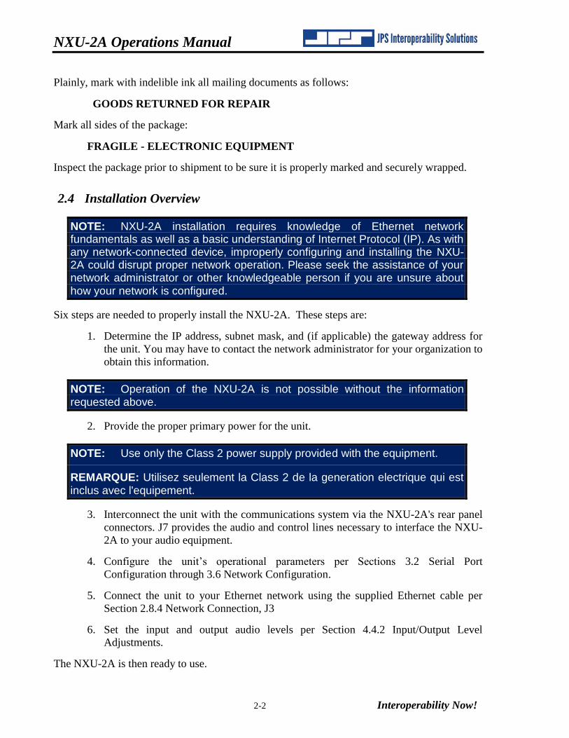
2.4 Installation Overview
NOTE: NXU-2A installation requires knowledge of Ethernet network fundamentals as well as a basic understanding of Internet Protocol (IP). As with any network-connected device, improperly configuring and installing the NXU-2A could disrupt proper network operation. Please seek the assistance of your network administrator or other knowledgeable person if you are unsure about how your network is configured.
Six steps are needed to properly install the NXU-2A. These steps are:
1. Determine the IP address, subnet mask, and (if applicable) the gateway address for
the unit. You may have to contact the network administrator for your organization to
obtain this information.
NOTE: Operation of the NXU-2A is not possible without the information requested above.
2. Provide the proper primary power for the unit.
NOTE: Use only the Class 2 power supply provided with the equipment.
REMARQUE: Utilisez seulement la Class 2 de la generation electrique qui est inclus avec l'equipement.
3. Interconnect the unit with the communications system via the NXU-2A's rear panel
connectors. J7 provides the audio and control lines necessary to interface the NXU-
2A to your audio equipment.
4. Configure the unit’s operational parameters per Sections 3.2 Serial Port
Configuration through 3.6 Network Configuration.
5. Connect the unit to your Ethernet network using the supplied Ethernet cable per
Section 2.8.4 Network Connection, J3
6. Set the input and output audio levels per Section 4.4.2 Input/Output Level
Adjustments.
The NXU-2A is then ready to use.
NXU-2A Operations Manual
Interoperability Now! 2-3
2.5 Installation Considerations
Careful attention to the following installation suggestions should result in the best unit/system
performance. Figure 2-1 provides overall unit dimensions.
The NXU-2A must be installed in a structure that provides both protection from the weather
and assurance of ambient temperatures between -10 and +55 degrees C. Since the unit is
neither splash proof nor corrosion resistant, it must be protected from exposure to salt spray.
When the unit is mounted in a cabinet with other heat-generating equipment, the use of a rack
blower is suggested to keep the cabinet interior temperature rise to a minimum.
NOTE: If the NXU-2A is installed in a high RF environment such as repeater system or other transmitter site, it is recommended that all cable assemblies be individually shielded, with the shield grounded to the ground pin on the terminal block for that module. For all D-subminiature connector cable assemblies, cable shields should be connected to connector shells so that they make contact with the grounded D-subminiature connector shells on the NXU-2A.
NOTE: For the DC input, the plug is the equipment disconnect device.
REMARQUE: Pour deconnecter le DC, retirez la prise qui est couramment connecte a l'equipement.
NXU-2A Operations Manual
2-4 Interoperability Now!
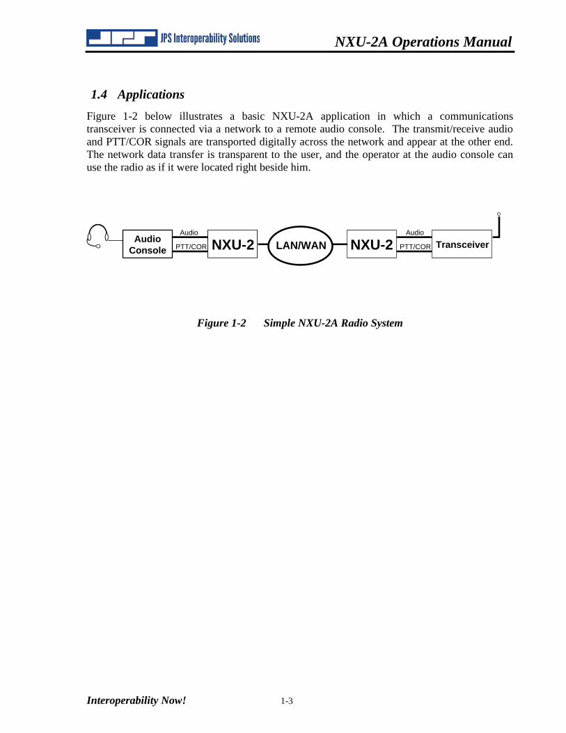
Figure 2-1 Outline Dimensions
NXU-2A Operations Manual
Interoperability Now! 2-5
Figure 2-2 Control and Connector Locations
NXU-2A Operations Manual
2-6 Interoperability Now!
2.5.1 Internal Configuration
The illustration below shows the NXU-2A with its top cover and rear panel removed. There is
normally no reason to remove the top cover, as the NXU-2A has no internal user-serviceable
configuration controls.
Figure 2-3 NXU-2A Internal View
NXU-2A Operations Manual
Interoperability Now! 2-7
2.6 Power Requirements
The NXU-2A is designed to operate from a nominal +12V DC supply. The unit will meet all
of its specifications over a voltage range of +11 to +15 VDC and will be damaged by a DC
source that delivers a constant (non-transient) DC voltage above this range. The DC power
consumption is 500 mA maximum. The AC adapter provided with the unit meets these
specifications.
NOTE: Use only the Class 2 power supply provided with the equipment.
REMARQUE: Utilisez seulement la Class 2 de la generation electrique qui est inclus avec l'equipement.
The NXU-2A is a microprocessor-controlled device. As with any such equipment, a very short
loss of power can cause operational problems and/or cause the unit to reset. The
communications link will be inoperable during the reset period. JPS recommends the NXU-2A
and associated equipment be connected to an AC power source that utilizes an uninterruptible
power system (UPS). If the overall site does not have UPS capability, the NXU-2A should be
plugged into a smaller UPS, such as those used for personal computer systems
2.7 Installation Checklist
Table 2-1 Basic Installation Checklist
Determine NXU-2A network parameters
such as IP address, subnet mask, and
gateway address.
You must assign these values. If you are not sure
how to determine these values, see the network
administrator for your organization.
Provide suitable power for the device. See section 2.6 Power Requirements.
Make interconnections. See Section 2.8.2 Audio Level Adjustment
Potentiometers and Input Test Point for External
Interconnect Information.
Configure NXU-2A parameters. See Section 3 Configuration.
Adjust audio levels. See Section 4.4.2.
2.8 Rear Panel Adjustments and Connectors
Refer to Figure 2-2 for a view of the NXU-2A Rear Panel. All rear panel connectors and
adjustment potentiometers are explained in the section below, starting at the left side of the
panel.
2.8.1 DC Input Connector, J6
The NXU-2A operates on a nominal +12 VDC. The power is applied through J6 via the “Wall
Cube” AC adapter provided with the unit.
NXU-2A Operations Manual
2-8 Interoperability Now!
2.8.2 Audio Level Adjustment Potentiometers and Input Test Point
A test probe may be inserted into the test point to measure the level of the incoming audio. See
Section 4.4.2 for input and output audio level setting instructions.
2.8.3 Connection to Radio or Other Four-Wire Device (J7)
The interface between the NXU-2A and associated radio or other audio device is made via J7
(Audio/Control) on the rear panel. J7 is a female DB-15 connector.
Note: an Audio Crossover Adapter, part number 0313 080515 is included with the NXU-2A.
This DB-15 male to DB-15 female adapter allows the use of radio cables developed specifically
for the JPS ACU-1000 Intelligent Interconnect system to be used with the NXU-2A. It provides
a crossover of transmit and receive audio as well as COR and PTT control signals. You only
need this adapter if you are planning to connect an NXU-2A to a radio and you are using a
cable specifically designed to connect an ACU-1000 to that radio. The adapter makes the
NXU-2A audio connector pinout match the one found on the ACU-1000. If you are wiring your
own cable, or if you are connecting the NXU-2A directly to an ACU-1000 then you don’t need
the Audio Crossover Adapter.
Table 2-2 NXU-2A Pinout (J7)
PIN Signal Description
1 Ground Ground connection.
2 Not used.
3 /AUX In 0 Auxiliary Input 0 - Active low.
4 /AUX Out 0 Auxiliary Output 0 - Active low.
5 Ground Ground connection.
6 Audio Input Balanced audio input.
7 Analog Ground Analog ground.
8 Audio Output Unbalanced Audio output.
9 Not used.
10 /AUX In 1 Auxiliary Input 1 - Active low; general purpose.
11 /AUX Out 1 Auxiliary Output 1 - Active low; general purpose.
12 /COR Input Input from radio COR, programmable active high or
low.
13 /PTT Out Output to radio PTT, active low, open drain.
14 Audio Input Balanced audio input.
15 Analog Ground Analog ground.
2.8.4 Network Connection, J3
The NXU-2A is connected to the Ethernet network via rear panel connector J3 using a standard
RJ-45 Ethernet Patch Cable (non-crossover). A six-foot long cable is included with the unit.
NXU-2A Operations Manual
Interoperability Now! 2-9
2.8.5 Serial Port Connection, J4
J4 is a standard RS-232 DCE serial port. It is a female DB-9 connector, and can be interfaced to
most PCs, typically standard DTE serial ports, using the DB-9 straight-through serial cable
included with the NXU-2A.
Table 2-3 J4 Serial Port Pinout
J4 pin Description
2 TX data
3 RX data
5 Ground
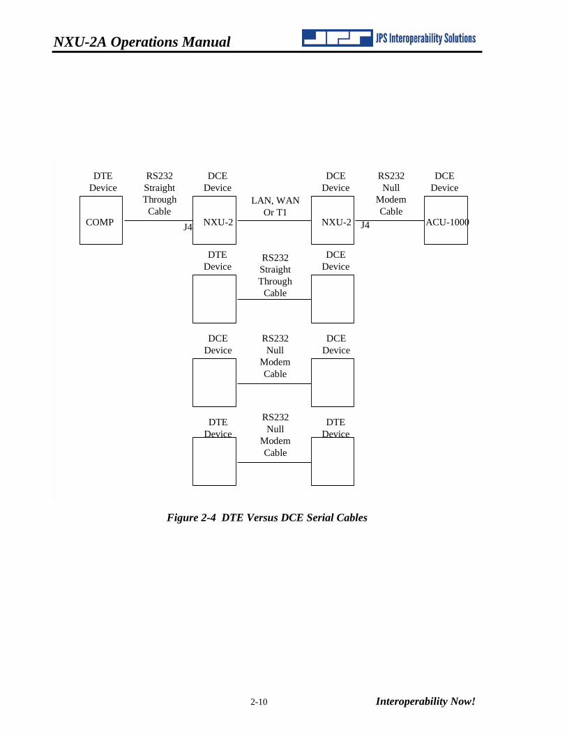
2.8.6 Connecting Equipment and Computers to an NXU-2A
The RS-232 serial cable supplied with the NXU-2A is a straight-through cable used to connect
the NXU-2A to a PC serial port. In order to connect the NXU-2A port to an ACU-1000, you
need a DB-9 male-male null modem cable, also called a crossover cable.
RS-232 serial devices are divided into two types. Devices which provide control information
are called DTE (Data Terminal Equipment) devices. Devices which accept control information
are called DCE (Data Communication Equipment) devices. In the "old days” the DTE devices
were terminals and computers, while the DCE devices were modems. The RS-232 standard
specified that DTE devices would connect to DCE devices using a straight-through cable. If
you wanted to connect two like devices (DTE to DTE or DCE to DCE) then you needed a null
modem (crossover) cable. The PC is a DTE device, and the NXU-2A and ACU-1000 are DCE
devices. That is why you need a crossover cable for connecting an ACU-1000 to an NXU-2A.
The following drawing shows typical cable requirements for connecting different devices to an
NXU-2A. See Figure 2-4 DTE Versus DCE Serial Cables.
NXU-2A Operations Manual
2-10 Interoperability Now!
LAN, WAN
Or T1
RS232
Straight
Through
Cable
RS232
Null
Modem
Cable
RS232
Null
Modem
Cable
RS232
Straight
Through
Cable
RS232
Null
Modem
Cable
DTE
Device
DTE
Device
DTE
Device
DCE
Device
DCE
Device
DCE
Device
COMP NXU-2 NXU-2 ACU-1000J4 J4
DTE
Device
DCE
Device
DCE
Device
DCE
Device
Figure 2-4 DTE Versus DCE Serial Cables
Interoperability Now 3-1
3 Configuration
3.1 General
This section explains all settings and level adjustments that configure the NXU-2A. It is not
necessary to remove the NXU-2A cover to configure the unit.
3.2 Configuration Details
Configuring an NXU-2A or pair of NXU-2As requires that you allocate an IP address for each
unit, and that you designate one unit as a Client and one unit as a Server (explained in
subsequent paragraphs). Initial configuration is accomplished by attaching a serial RS-232
terminal to J4. If the unit already has an IP address and is on a network, configuration may be
done by connecting to the unit’s IP address via telnet or with a web browser. Each method of
configuration is discussed below.
NOTE: The NXU-2A comes from the factory configured as a Server with the following default settings:
IP Address: 192.168.1.200
Subnet Mask 255.255.255.0
Gateway IP 0.0.0.0
If the above network parameters are compatible with your network then you may attach the
NXU-2A to your network and use your web browser or telnet client to configure the NXU-2A as
outlined in Section 3.6 Network Configuration.
NOTE: To restore the factory default conditions, remove and reapply power to the unit while rear panel switch “SW1” (DEFAULTS) is depressed. When the front panel LED’s have blinked, release the switch, and the unit will be operational using the JPS factory default parameters. Any previously assigned user parameters will be lost during this process.
3.3 Serial Port Configuration
To configure the NXU-2A using the serial port, connect a standard serial cable from a suitable
COM port on your PC to J4 on the NXU-2A rear panel. A standard DB-9 straight-through
cable (which should work on most PCs) is included with the NXU-2A. The NXU-2A comes
pre-configured with the serial port set at 115200-baud, 8 data bits, no parity, and 1 stop bit. No
hardware flow control is used or needed. In order to configure the NXU-2A you will need to
know which COM port you are connected to on your PC.
NXU-2A Operations Manual
3-2 Interoperability Now!
The NXU-2A includes a Windows program (the NXU-2A Setup Utility). It provides a graphical user interface for configuring the unit via the serial port. This program allows NXU-2A settings to be chosen from a menu and then sends the appropriate commands to the device. Alternatively the NXU-2A may be configured manually using any RS-232 terminal program. Both methods are described. If you want to use the NXU-2A Setup Utility you may skip to Section
3.5.2.
3.3.1 Configuration Using an RS-232 Terminal Program
A terminal program is needed to communicate with the NXU-2A for initial configuration. A
suitable Windows terminal program, MTTTY.EXE, is included with the unit. This program
may be run directly from the floppy diskette or it may be copied to your hard drive and
executed from there. This program is also available from JPS Customer Service.
After running MTTTY and setting the parameters listed above your screen should look like
this:
Figure 3-1 MTTTY Terminal Screen
Choose the COM port appropriate for your computer and then click the Connect box.
Note: When using MTTTY you must click the Connect box to enable serial communications.
NXU-2A Operations Manual
Interoperability Now! 3-3
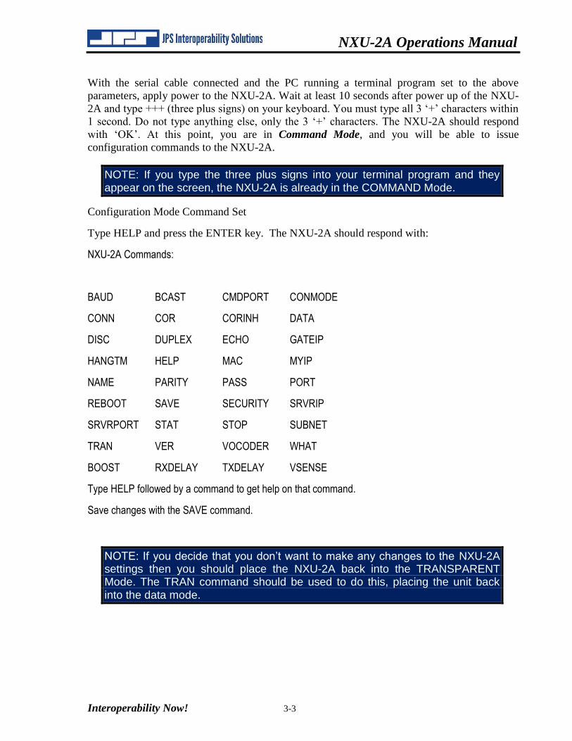
With the serial cable connected and the PC running a terminal program set to the above
parameters, apply power to the NXU-2A. Wait at least 10 seconds after power up of the NXU-
2A and type +++ (three plus signs) on your keyboard. You must type all 3 ‘+’ characters within
1 second. Do not type anything else, only the 3 ‘+’ characters. The NXU-2A should respond
with ‘OK’. At this point, you are in Command Mode, and you will be able to issue
configuration commands to the NXU-2A.
NOTE: If you type the three plus signs into your terminal program and they appear on the screen, the NXU-2A is already in the COMMAND Mode.
Configuration Mode Command Set
Type HELP and press the ENTER key. The NXU-2A should respond with:
NXU-2A Commands:
BAUD BCAST CMDPORT CONMODE
CONN COR CORINH DATA
DISC DUPLEX ECHO GATEIP
HANGTM HELP MAC MYIP
NAME PARITY PASS PORT
REBOOT SAVE SECURITY SRVRIP
SRVRPORT STAT STOP SUBNET
TRAN VER VOCODER WHAT
BOOST RXDELAY TXDELAY VSENSE
Type HELP followed by a command to get help on that command.
Save changes with the SAVE command.
NOTE: If you decide that you don’t want to make any changes to the NXU-2A settings then you should place the NXU-2A back into the TRANSPARENT Mode. The TRAN command should be used to do this, placing the unit back into the data mode.
NXU-2A Operations Manual
3-4 Interoperability Now!
3.3.2 Command Summary
This is a full list of the commands available in the NXU-2A command mode. More detail is
given on the following pages. You can get a one-line summary of each command by typing
HELP followed by the command.
BAUD <rate> - Set the serial port baud rate
BCAST <mode> - Sets the broadcast mode (0) Normal (1) Connectionless (2) Multicast
CMDPORT <port number> - Set the port used to receive telnet and WAIS commands
CONMODE <0/1> - Places unit in CLIENT (0) or Server (1) mode
CONN <IP address> - Connect this client to a server at IP address
COR <0/1/23> - Sets COR active low (0), high (1), VOX (2), or VMR (3)
CORINH <time> - Set COR inhibit time to 0,500,1000,2000,3000, or 4000 mS
DATA <7/8> - Set the serial port data bits
DISC - Break this client's current connection
DUPLEX <0/1> - Select either full duplex (0) or half duplex (1) for audio
ECHO <ON/OFF> - Enables/disables character echo to console
GATEIP <ip address> - Set gateway IP address for this unit
HANGTM <time> - Set VOX hang time to 500,1000,2000,3000, or 4000 mS
MAC – Return the Ethernet MAC address of this unit
MYIP <ip address> - Set the IP address of this unit
NAME <text description> - Give this unit a name
PARITY <O/E/N> - Set the serial port parity to Odd, Even, or None
PASS <password> - Assign a password for web access
PORT <port number> - Set the IP port used by this unit
REBOOT - Restart this unit
SAVE - Save NXU-2A settings to FLASH memory and restart
SECURITY <security level> - Set the security level (0-255)
SRVRIP <ip address> - Set the IP address of the NXU-2A server
SRVRPORT <port number> - Set the port where to send VOIP traffic
STAT - Return this client's current connection status
NXU-2A Operations Manual
Interoperability Now! 3-5
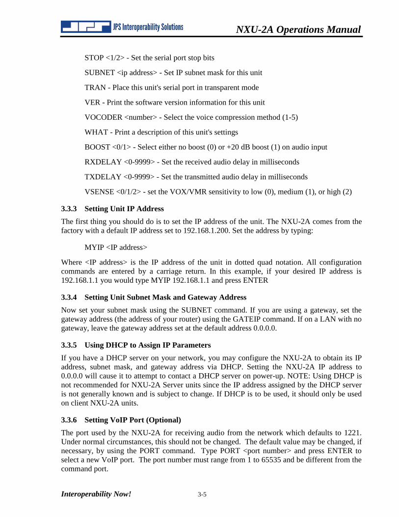
STOP <1/2> - Set the serial port stop bits
SUBNET <ip address> - Set IP subnet mask for this unit
TRAN - Place this unit's serial port in transparent mode
VER - Print the software version information for this unit
VOCODER <number> - Select the voice compression method (1-5)
WHAT - Print a description of this unit's settings
BOOST <0/1> - Select either no boost (0) or +20 dB boost (1) on audio input
RXDELAY <0-9999> - Set the received audio delay in milliseconds
TXDELAY <0-9999> - Set the transmitted audio delay in milliseconds
VSENSE <0/1/2> - set the VOX/VMR sensitivity to low (0), medium (1), or high (2)
3.3.3 Setting Unit IP Address
The first thing you should do is to set the IP address of the unit. The NXU-2A comes from the
factory with a default IP address set to 192.168.1.200. Set the address by typing:
MYIP <IP address>
Where <IP address> is the IP address of the unit in dotted quad notation. All configuration
commands are entered by a carriage return. In this example, if your desired IP address is
192.168.1.1 you would type MYIP 192.168.1.1 and press ENTER
3.3.4 Setting Unit Subnet Mask and Gateway Address
Now set your subnet mask using the SUBNET command. If you are using a gateway, set the
gateway address (the address of your router) using the GATEIP command. If on a LAN with no
gateway, leave the gateway address set at the default address 0.0.0.0.
3.3.5 Using DHCP to Assign IP Parameters
If you have a DHCP server on your network, you may configure the NXU-2A to obtain its IP
address, subnet mask, and gateway address via DHCP. Setting the NXU-2A IP address to
0.0.0.0 will cause it to attempt to contact a DHCP server on power-up. NOTE: Using DHCP is
not recommended for NXU-2A Server units since the IP address assigned by the DHCP server
is not generally known and is subject to change. If DHCP is to be used, it should only be used
on client NXU-2A units.
3.3.6 Setting VoIP Port (Optional)
The port used by the NXU-2A for receiving audio from the network which defaults to 1221.
Under normal circumstances, this should not be changed. The default value may be changed, if
necessary, by using the PORT command. Type PORT <port number> and press ENTER to
select a new VoIP port. The port number must range from 1 to 65535 and be different from the
command port.
NXU-2A Operations Manual
3-6 Interoperability Now!
3.3.7 Client/Server Selection
Whether the unit will be a client (a unit which can make and break connections) or a server (a
unit which only accepts connections from a client) will need to be decided. This selection is
made with the CONMODE command. CONMODE 0 configures the unit as a client, while
CONMODE 1 configures the unit as a server. For a client unit, you also need to set the IP
address and port of the corresponding server with the SRVRIP and SRVRPORT commands.
For example, if a client unit is going to be connected to a server NXU-2A at address
192.168.1.10 and port 1221, then the commands must be issued:
SRVRIP 192.168.1.10
SRVRPORT 1221
On the client unit, if you do not want the client unit to connect to a server automatically at
power-up then set the server IP address to 0.0.0.0 by typing SRVRIP 0.0.0.0.
Note: The server port on a client unit corresponds to the VoIP port on the server unit that the
client unit is going to connect to. Also, the client unit’s VoIP port does not need to match the
server unit’s VoIP port (or client unit’s server port) for the two units to communicate. The
server unit will automatically determine where to send audio so the client unit receives it.
3.3.8 COR and VOX Settings
The NXU-2A uses the COR (Carrier Operated Relay) or equivalent signal from your radio to
determine when to send audio data across the network. When the COR input is active, audio is
transferred to the other side of the network. The COR command allows you to select the
polarity of the COR input. If a COR output signal is not available, you may select VOX (Voice
Operated Switching). VOX operation uses the detection of an audio signal from your radio or
other audio device to control the flow of audio from the NXU-2A.
Select the polarity of the COR input by using the COR command. COR 0 selects active low
COR, while COR 1 selects active high COR sense. COR 2 selects VOX mode. In VOX mode,
no connection to the NXU-2A COR input is required, since the audio input level itself is used
to determine when a signal is present. COR 3 selects VMR (Voice Modulation Recognition)
mode. In VMR mode the unit must detect speech content before a signal is determined to be
present. In order to conserve network bandwidth, digital audio packets are only sent when COR
is active. If using the NXU-2A in an application where the connected equipment does not
support the COR line, then the COR line must either be tied to its active state (in which case
audio will be sent across the network continuously) or you must select VOX or VMR mode. In
any case, the COR, VOX, or VMR mode must be set properly since the NXU-2A uses this
setting to determine when to send audio data across the network.
3.3.9 Duplex Setting
The NXU-2A allows full-duplex audio operation. Audio can be received and transmitted at the
same time. In some applications this is required, but in other applications this may not be
desirable. For example, if the system echoes back the transmitted audio to provide sidetone
monitoring the resulting audio will be slightly delayed. Listening to a delayed version of your
own voice can be distracting, and in such cases it would be better to use half-duplex audio. Use
NXU-2A Operations Manual
Interoperability Now! 3-7
the DUPLEX command to set full- or half-duplex. DUPLEX 0 selects full-duplex operation
(the default) while DUPLEX 1 selects half-duplex.
3.3.10 VOX Hang Time
When VOX mode is enabled, you may also adjust the VOX hang time. This is the amount of
time the VOX remains active after the input signal falls below the VOX threshold, and may be
set to 500, 1000, 2000, 3000, or 4000 milliseconds. This is useful to prevent the VOX from
dropping out between words or syllables. Use the HANGTM command followed by 500, 1000,
2000, 3000, or 4000 to select the hang time. The factory default is 500 milliseconds.
3.3.11 COR Inhibit Time
In some applications it may be necessary to inhibit the NXU-2A’s response to the COR input
(whether hardwired COR or VOX) for a brief period of time (and under certain circumstances)
in order to avoid problems with the “ping pong” effect.
The “ping-pong” effect can occur when the COR output of a device is activated momentarily
by the device when it switches out of the TX mode. There are varieties of reasons why this can
happen (including squelch tails on some radios), and it may occur with COR or VOX, but the
result is the same.
To illustrate the problem, assume that there are two radios connected over a network by a pair
of NXU-2As. An active COR at one end of the network creates an active PTT at the other end.
When the COR of Radio 1 is active, Radio 2 is transmitting, and vice versa. Consider what can
happen when the switch out of the TX mode causes a momentary active COR output:
Radio 1 COR becomes deactivated, so the Radio 2 switches out of the TX mode and
activates its COR output momentarily. This momentary Radio 2 active COR signal
causes Radio 1 to switch momentarily to TX mode, and when it quickly drops back out
of the TX mode its own COR output is momentarily activated. This will once again put
Radio 2 in the TX mode, causing an endlessly repeated cycle where the radios “ping-
pong” back and forth and in and out the TX mode.
The COR Inhibit feature prevents this problem by ignoring any active COR input that occurs
just after the NXU’s TX output command is de-activated. The unit ignores the COR input
(whether hardwired or VOX) only in the specified interval immediately following the
inactivation of its PTT output. Use the CORINH command followed by 500, 1000, 2000, 3000,
or 4000 to select the COR inhibit time in milliseconds. Type CORINH 0 to disable the COR
inhibit feature. The COR inhibit time should be set as long as required to prevent the “ping-
pong effect”, but no longer, or the beginning of a valid audio signal being transferred might be
lost.
3.3.12 Serial Port Settings
The serial port baud rate may be set using the BAUD command. Valid baud rates are 300,
1200, 2400, 4800, 9600, 19200, 38400, 57600, and 115200. The number of data bits may be
programmed to 7 or 8 using the DATA command, while the number of stop bits may be
programmed to 1 or 2 using the STOP command. The serial port parity may be programmed to
odd, even, or none by typing the PARITY command followed by O, E, or N.
NXU-2A Operations Manual
3-8 Interoperability Now!
3.3.13 Voice Compression Settings
In order to send voice information over an IP network efficiently the NXU-2A uses digital
signal processing algorithms to compress the voice information so that it requires less network
bandwidth. The NXU-2A offers several different voice compression methods to support a
variety of applications. For example, some compression methods work well with voice and
provide a high amount of compression, but do not handle signaling tones very well. Other
methods handle tones and voice, but use more network bandwidth because they offer less
compression. You may select the method from the following voice compression schemes that
optimizes the trade-offs for your particular application:
1. GSM 13Kbps - Suitable for voice communications only. Should not be used if any tone
signaling is required. Offers the greatest compression with reasonable voice quality. This is the
default setting.
2. ADPCM 16Kbps – Suitable for voice or tone signaling. Offers good voice compression, but
the voice quality is lower than the other compression methods.
3. ADPCM 24Kbps – Suitable for voice or tone signaling. Offers less compression than
ADPCM 16Kbps but the voice quality is higher.
4. ADPCM 32Kbps – Suitable for voice or tone signaling. Offers still less compression, but
the voice quality is the best of the ADPCM compression types.
5. PCM 64Kbps – Suitable for voice or tone signaling. Offers the highest quality of all
compression methods, but provides the least compression. You should use this method only if
your network offers low latency and good throughput.
You may select a compression method with the VOCODER command followed by the number
of the compression method (1-5). If you are only using voice in your application, you should
select GSM 13Kbps (1). If you plan to use any tone signaling, you should select 2, 3, 4, or 5 in
accordance with your network bandwidth and voice quality requirements.
3.3.14 Security Settings
The NXU-2A may be configured, monitored, and controlled remotely via its network interface
using a web browser or a telnet client. In some instances, it may be desirable to limit access via
one or both of these methods, or to selectively limit the things that may be done remotely. The
SECURITY command allows various levels of security to be set in order to limit remote
access. Additionally, a password may be assigned to limit access via a web browser. Refer to
the chapter on Security for detailed information on setting the NXU-2A security parameters.
3.3.15 Ethernet MAC Address
The Ethernet MAC address of the NXU-2A may be read using the MAC command. When
MAC is typed the 48-bit Ethernet MAC address will be printed as a sequence of two digit
hexadecimal numbers separated by dashes. No two NXU-2A units have the same MAC
address, so this may be used as an electronic serial number if desired. It cannot be changed by
the user.
NXU-2A Operations Manual
Interoperability Now! 3-9
3.3.16 Command Port
The port used by the NXU-2A for receiving commands via the telnet protocol or from a WAIS
Controller. The value defaults to 23 and under normal circumstances should not need to be
changed. If necessary, the command port may be changed by using the CMDPORT command.
Type CMDPORT <port number> and press ENTER. The port number must range from 1 to
65535 and must be different than the VoIP port.
3.3.17 Input Level Boost +20db
The receive input level may optionally be boosted by +20db in order to accommodate low level
signal sources. Provisioning via the web interface allows selecting either “No Boost” or,
“Boost +20db” in the ‘RX Boost Mode’ field.
3.3.18 TX Delay
Additional delay may be provided to the transmit audio path. Via the web interface ‘TX Delay
(mS)’ field, the user may introduce up to 10 seconds of delay, in specified in 1 mS increments.
Upon editing the field with numeric data, the NXU-2A will round to the nearest 100mS
interval. When additional delay is used, the PTT\ signal will be asserted prior to the delayed
audio being presented, allowing LMR trunking systems to be accessed without audio loss.
3.3.19 RX Delay
Additional delay may be provided to the receive audio path. Via the web interface ‘RX Delay
(mS)’ field, the user may introduce from 0 to 10 seconds of delay, specified in 1 mS
increments. Upon editing the field with numeric data, the NXU-2A will round to the nearest
100mS interval. When additional delay is used, the received audio will be delayed before
being sent to the network.
3.3.20 VMR
Voice Modulation Recognition has been added to allow interfacing with radios which do not
provide a separate COR signal. VMR provides a more robust method of ‘COR Sensing’ than
VOX alone. VMR mode may be selected via the web interface ‘COR Sense’ field pulldown
menu. When VMR mode is chosen, the hardware COR signal is ignored, and audio content
with the appropriate speech characteristics is allowed to simulate the COR signal.
3.3.21 VOX and VMR Sensitivity Adjustments
When either VOX or VMR COR sensing is selected, three levels of sensitivity adjustments are
provided to allow greater flexibility. Via the web interface, “Low” sensitivity requires more
signal content to recognize and simulate COR activity. “High” sensitivity requires less signal
content to recognize and simulate COR activity. The default sensitivity is “Medium”.
3.3.22 Restoring Factory Defaults
The NXU-2A allows the user to restore the original factory default operating conditions. This
may be useful if the unit has been incorrectly configured, and it is necessary to return to a well-
defined state. To restore the factory default conditions, the power to the unit needs to be
removed and restored while rear panel switch “SW1” (DEFAULTS) is depressed. When the
front panel LED’s have blinked, the switch may be released, and the unit will be operational
using the JPS factory default parameters. The IP address will return to “192.168.1.200”, which
will allow web configuration. All other previously assigned user parameters will be lost during
this process.
NXU-2A Operations Manual
3-10 Interoperability Now!
3.4 Network Management: SNMP support
The NXU-2A has the capability to support Simple Network Management Protocol (SNMP).
By default, the SNMP process (agent) is enabled and running, but may be disabled by changing
the “SECURITY” Setting (see section on SECURITY). The Management Information
Database [MIB] associated with the NXU-2A may be obtained by contacting customer support
at JPS Interoperability Solutions.
NOTE: SNMP not functional in current revision on NXU-2A software. Contact Customer Service for information on upcoming availability
NXU-2A Operations Manual
Interoperability Now! 3-11
3.5 Communications Mode
The NXU-2A has three communications modes: Normal, Connectionless, and Multicast.
The default mode is Normal; this consists of a TCP connection initiated by a client unit to a
server unit for traffic to be exchanged between the two units’ serial ports along with a unicast
UDP channel for VoIP traffic. This is the standard mode and should be used for one-to-one
unit operations.
Connectionless mode consists solely of a unicast UDP channel for VoIP traffic (along with the
status bits such as PTT and COR) between the NXU-2A and another unit. No serial traffic is
exchanged. This mode is reserved for special applications such as the JPS WAIS (Wide Area
Interoperability System) and should not be used for day-to-day operation.
Multicast is a network routing technique that allows IP packets to be sent simultaneously from
a single source to multiple destinations. Rather than sending the packet to each destination
independently, the packet is sent to a multicast group identified by a single, specialized, Class
D IP address. This is an IP address in the range of 224.0.0.0 to 239.255.255.255. Multicast
mode on the NXU-2A consists of a multicast UDP channel for VoIP and status bit traffic. No
serial traffic is exchanged. It can be used whenever more than two units wish to hear each
other’s’ audio.
The NXU-2A communications mode can be set using the BCAST command. BCAST 0 sets
the unit to Normal mode, BCAST 1 sets the unit to Connectionless mode, and BCAST 2 sets
the unit to Multicast mode. Once again, Connectionless mode is reserved for special
applications and should not be used for day-to-day operation. Its use outside the advisement of
JPS Interoperability Solutions is not supported.
To use a set of NXU-2As in Multicast mode, they must all be put into the same multicast
group. To do this, first select a Class D IP address, port, and vocoder for use by the entire
group.
Then configure each NXU-2A in the group so that:
Its server IP address is the IP address of the multicast group
Both its server port and VoIP port are the ports selected for the multicast group
It’s set to use the vocoder selected for the group.
Once these configuration steps are complete, packets sent by any unit in a multicast group will
be received by all other units in that group.
Please note that multicast operation is guaranteed to work only in LAN environments or private WANs where multicast enabled routers are in use. Multicast mode will not work over the Internet because not all routers on the Internet are multicast enabled.
NXU-2A Operations Manual
3-12 Interoperability Now!
3.5.1 Store Setup Changes with SAVE Command
After any configuration changes have been made, SAVE must be typed in order to store the
new settings in memory. The NXU-2A will automatically restart after changes have been
saved. If you do not make any changes and want to return the serial port to the data mode, type
TRAN to place the serial port in transparent mode.
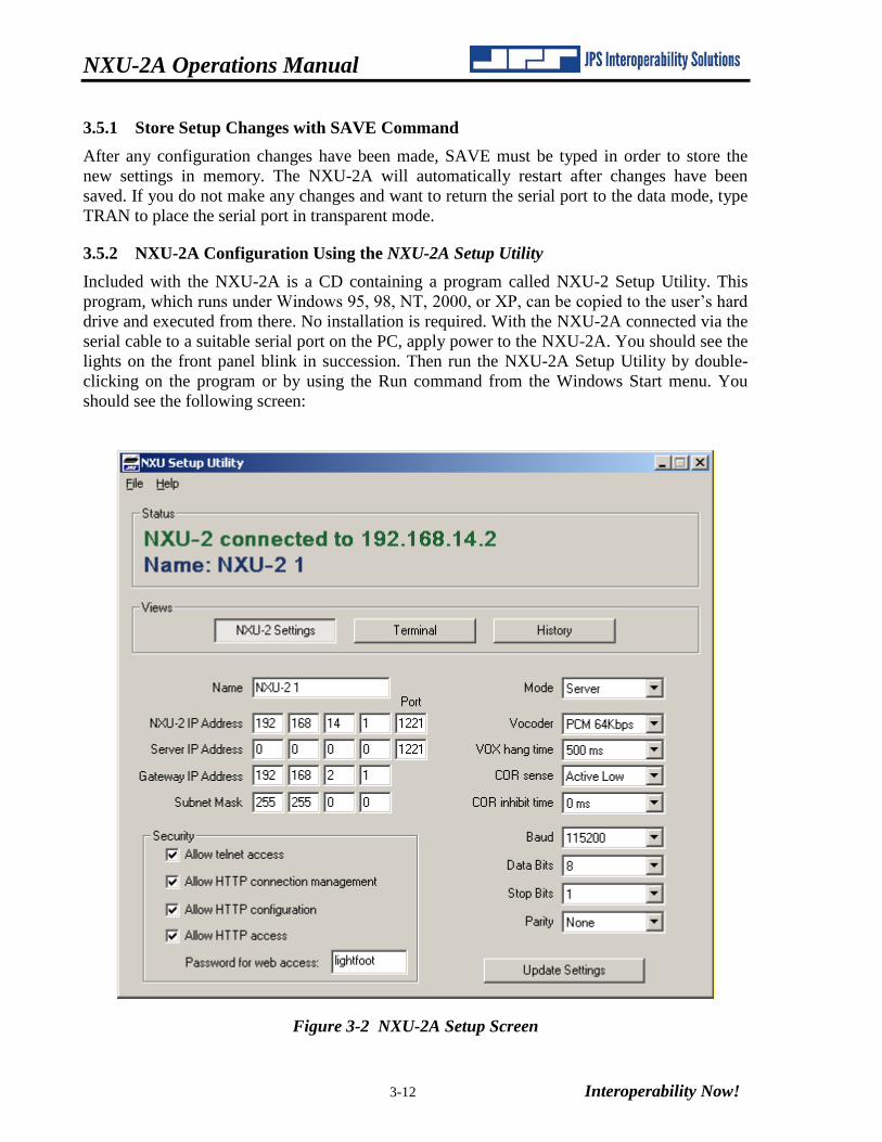
3.5.2 NXU-2A Configuration Using the NXU-2A Setup Utility
Included with the NXU-2A is a CD containing a program called NXU-2 Setup Utility. This
program, which runs under Windows 95, 98, NT, 2000, or XP, can be copied to the user’s hard
drive and executed from there. No installation is required. With the NXU-2A connected via the
serial cable to a suitable serial port on the PC, apply power to the NXU-2A. You should see the
lights on the front panel blink in succession. Then run the NXU-2A Setup Utility by double-
clicking on the program or by using the Run command from the Windows Start menu. You
should see the following screen:
Figure 3-2 NXU-2A Setup Screen
NXU-2A Operations Manual
Interoperability Now! 3-13
NOTE: The program defaults to serial port COM1. If you are using a different serial port you
must select the appropriate serial port from the File menu.
Make the appropriate changes by selecting the various menu options. When you have finished
making configuration changes, click the Update Settings button to save the new configuration
information in the NXU-2A. The NXU-2A will restart and the new settings will then be in
effect.
The NXU-2A Setup Utility allows the user to see the actual commands being sent to and
received from the NXU-2A. Click on the Terminal button to bring up the terminal window. If
you wish to enter an NXU-2A command manually you may type it into the Command Entry
window and click Send. If an NXU-2A has been disconnected or powered down (and is no
longer in command mode) it may be placed in command mode by clicking the Attention button.
Figure 3-3 NXU-2A Terminal Screen
NXU-2A Operations Manual
3-14 Interoperability Now!
The NXU-2A Setup Utility may also be used to keep records on various NXU-2A devices.
Once an NXU-2A has been configured, click on the History button to bring up the history
window as shown below. To add the current unit to the configuration history, type a name for
the unit into the box beside the Add Current button and click the button. The NXU-2A will be
added to the list of units shown in the NXU-2A List window. To review the settings for a
particular unit, simply choose it from the list and the settings will be displayed. To remove a
unit from the list, highlight the unit and click Remove.
Figure 3-4 NXU-2A History Screen
NXU-2A Operations Manual
Interoperability Now! 3-15
3.6 Network Configuration
After the NXU-2A has been assigned a valid IP address and is on the network, you may
configure it via telnet or a web browser. For telnet, use your PC’s telnet client to connect to the
IP address of the NXU-2A. Once a telnet connection is made, configuration of the NXU-2A is
identical to configuration via the serial port as described in Section 3.3 except that there is no
need to type +++ to enter command mode. The telnet connection to the NXU-2A will
automatically disconnect after two minutes of no activity, or LOGOUT may be typed to
disconnect the telnet connection manually.
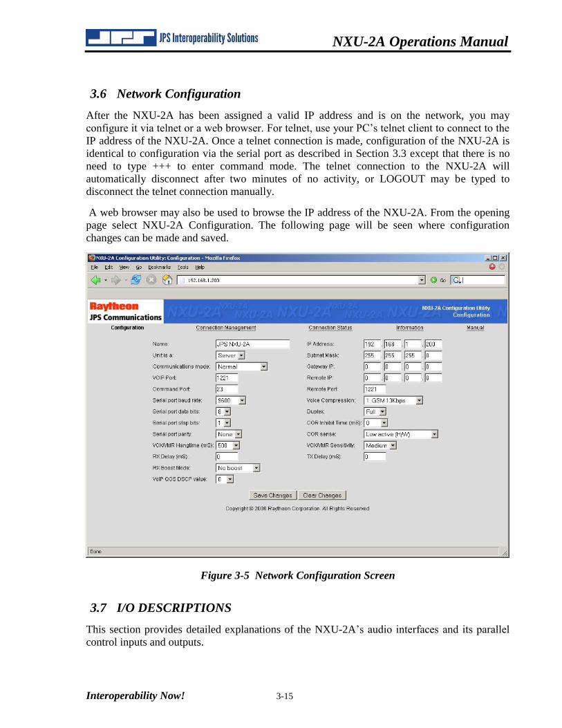
A web browser may also be used to browse the IP address of the NXU-2A. From the opening
page select NXU-2A Configuration. The following page will be seen where configuration
changes can be made and saved.
Figure 3-5 Network Configuration Screen
3.7 I/O DESCRIPTIONS
This section provides detailed explanations of the NXU-2A’s audio interfaces and its parallel
control inputs and outputs.
NXU-2A Operations Manual
3-16 Interoperability Now!
3.7.1 Audio Input
The NXU-2A audio input is 47K ohm, balanced. It can be used as an unbalanced input by
grounding one half of the balanced pair and connecting the single-ended input to the remaining
half. The use of balanced inputs and shielded cables is recommended for superior immunity to
noise.
The audio input will accept signal levels from –30 to +11 dBm. Internal circuitry is used to
amplify or attenuate this input as necessary to optimize the level to the DSP. The signal level is
adjusted by the IN LVL potentiometer accessible from the rear panel. The input is set to 0
dBm when shipped. This means the IN LVL potentiometer is adjusted so that an audio input of
0 dBm provides the correct level to the DSP circuitry.
3.7.2 Audio Input Test Point
Access to an audio test point, TP1, is provided via the rear panel so the actual audio signal
voltage applied to the A/D converter can be measured with an AC voltmeter. The correct level
for best operation as measured at TP1 is about 0.2V or –12dBm (600 ohm reference.)
3.7.3 Audio Output
The audio output from the NXU-2A is a low impedance (10 ohm) unbalanced AC coupled
output. The output level is adjusted by the OUT LVL potentiometer accessible from the rear
panel. This output provides a 0 dBm nominal level; +15 dBm clipping into a 600 ohm load.
The audio output will supply signal levels from –30 to +11 dBm.
3.7.4 COR Input
The COR input to the NXU-2A is a high impedance input and can be programmed to be active
high or active low. In the active low configuration the input is pulled up to +5V DC internally
through a 47K ohm resistor. In the active high configuration the input is pulled down to ground
through a 22K ohm resistor. The logic threshold is 2.5V DC nominal, and the input is protected
from momentary surges up to +100 V DC.
3.7.5 AUX Inputs
The AUX inputs (AUX IN0 and AUX IN1) are high impedance inputs, and are always active
low. They are pulled up to +5V DC internally through a 47K ohm resistor. The logic threshold
is 2.5V DC nominal, and the input is protected from momentary surges up to +100 V DC.
3.7.6 PTT Output
The PTT output from the NXU-2A is an open drain type. It can sink up to 100 mA of current,
and can withstand open-circuit voltages up to +60V DC. In order to avoid conflicts with
internal pull-up resistors on the PTT lines of some radio equipment, there is no internal pull-up
resistor on the NXU-2A PTT output.
3.7.7 AUX Outputs
The AUX outputs from the NXU-2A (AUX OUT0 and AUX OUT1) are open drain types.
They can sink up to 100 mA of current, and can withstand open-circuit voltages up to +60V
DC. These lines are pulled up to +5V DC through a 47K ohm resistor.
Interoperability Now 4-1
4 Operation
4.1 General
This Section contains information and instructions required for proper operation of the NXU-
2A. Refer to Figure 2-2 Control and Connector Locations for views of controls and
connectors.
4.2 Front Panel Indicators
All front panel indicator LEDs are explained below, starting at the left side of the unit.
4.2.1 Power LED
This yellow LED is lit whenever DC power is applied to the unit.
4.2.2 Link Active LED
The green Link Active LED is illuminated whenever the NXU-2A has an IP connection open to
another NXU-2A on the network. If this indicator is not lit, either the NXU-2A does not have
an active VoIP connection or the connection has been lost.
4.2.3 Channel Active LED
This green LED is lit whenever COR is active. This also indicates that the NXU-2A is sending
audio data across the IP link.
4.2.4 Audio Input LED
This yellow LED is provided as a visual aid in setting the proper input audio level for optimal
operation. See Section 4.4.2 Input/Output Level Adjustments for instructions.
4.3 Rear Panel Connectors, Adjustments and Level Potentiometers
Section 2.8 Rear Panel Adjustments and Connectors contains full explanations and pin-outs for
all rear panel connectors. Figure 2-2 displays connector locations.
4.4 NXU-2A Operation
Basic operation and control of the NXU-2A is discussed in the following paragraphs. These
instructions assume the NXU-2A has already been correctly configured per Section 3
Configuration.
NXU-2A Operations Manual
4-2 Interoperability Now
4.4.1 Operation at Power-Up
When the units have been connected and configured and are attached to the network the client
will automatically connect to the server when power is applied.
If no default server has been specified for the client to contact (using the SRVRIP command; see Section 3.3.7, Client/Server Selection), the client unit will wait until a manual connection is requested, either via serial or telnet commands or via the web interface. If the client is able to connect to the server, the LINK ACTIVE indicator will light indicating that a connection has been made.
4.4.2 Input/Output Level Adjustments
At this point, the audio input level to the NXU-2A may be set by adjusting the IN LVL control
on the rear panel. With normal audio input applied at J7, adjust the IN LVL control until the
AUDIO INPUT indicator flashes on voice peaks. The OUT LVL control sets the audio output
level from the NXU-2A and may be adjusted to the level suitable for the equipment connected
to the unit.
The proper audio input level may also be set by connecting an AC voltmeter to the test point
TP1 on the real panel and adjusting the IN LVL control for an average audio level of about
0.2V or –12dBm.
4.4.3 COR Input Description
The COR input on J7 controls the flow of data across the network. When COR is not active the
units will send a keep-alive packet every 4 seconds just to keep the connection from timing out.
If a unit has an active COR input, that unit’s audio input will be transferred across the network
and will appear at the audio output on J7 at the other unit. While the COR input of an NXU-2A
is active, the PTT output will remain active on another NXU-2A it’s connected to. The audio
channels are independent, and full duplex operation is possible. If the radio or other audio
equipment does not have a COR output, it’s possible to tie the NXU-2A COR input line to the
active state so that data will be transmitted continuously.
4.4.4 RS-232 Serial Data
RS-232 data at J4 is sent across the network connection to the RS-232 connector on the unit at
the other end of the link. Any data input to the RX DATA line on one end will appear at the TX
DATA line on the other end. The serial port data may be sent even while audio is being
transmitted as the two functions are independent. Audio and RS-232 data are multiplexed over
the same IP connection.
NXU-2A Operations Manual
Interoperability Now! 4-3
Note: If data is to be transferred across the IP link, the NXU-2A serial port must not be in the Command Mode (see Section 3.3.1). Be sure to return the unit to the Transparent Mode (by issuing a TRAN command) if you have placed the unit in Command Mode.
4.4.5 Auxiliary I/O
The NXU-2A has two sets of independent inputs and outputs that may be used for control of
the user’s equipment. AUX IN 0 and AUX IN 1 are active-low inputs which, when activated on
one end, will cause AUX OUT 0 and AUX OUT 1 on the other end to become active. The
AUX OUT lines are open drain devices and each is capable of sinking 100 mA. Note: the
auxiliary I/O lines are designed for switching and control applications, and do not have quick
enough response times to send or receive data.
4.5 Controlling Connections
Normally the NXU-2A client automatically connects to the preprogrammed NXU-2A server
when power is applied. The user may also manually control the connection state of the NXU-
2A client. This can be done via the serial port (by entering command mode as described in
Section 3.3.1) or via the network using Telnet or a Web Browser.
4.5.1 Serial or Telnet Control
When using the serial port (in command mode) or Telnet, the user may disconnect a client from
a server by typing:
DISC
A connection may be made to a server by typing:
CONN <IP address>
The status of these commands may be viewed by typing:
STAT
STAT returns the following responses:
CON <IP address> The unit is connected to an NXU-2A at address <IP address>
DIS The unit is not connected
ATT <IP address> The unit is attempting a connection to <IP address>
Depending upon the characteristics of the network, the CONN and DISC commands may not
take effect immediately. In order to determine when a CONN or DISC command has
completed, issue the STAT command repeatedly to poll the status of the connection.
NXU-2A Operations Manual
4-4 Interoperability Now
4.5.2 Web Browser Control
The NXU-2A client connection may be managed by browsing to the NXU-2A client IP address
and selecting the Connection Management menu option. The user may then issue connect or
disconnect commands via the web browser.
Figure 4-1 NXU-2A Connection Management Screen
NXU-2A Operations Manual
Interoperability Now! 4-5
4.6 Security
In some applications, it may be desirable to restrict network access to the configuration or
connection management features of the NXU-2A. The NXU-2A can be programmed to one of
several different levels of security by using the SECURITY command in the command mode.
Possible settings are listed below:
SECURITY 0 Full access via serial port, telnet, or web browser
SECURITY 8 Telnet access disabled
SECURITY 16 Password required for HTTP (web) access
SECURITY 32 Connection management via HTTP disabled
SECURITY 64 Configuration via HTTP disabled
SECURITY 128 All HTTP (web) access disabled
The above numbers may be added together to select various security options. For example,
setting the security level to 136 (128+8) disables both telnet and HTTP access. Setting security
to 96 (64+32) allows the connection status to be monitored by HTTP, but no configuration or
connection changes may be made via HTTP. Setting security to 24 (8+16) disables telnet
access and requires the user to enter a password for HTTP access.
Note: The default security setting from the factory is SECURITY 0, which places no restrictions on network access to the NXU-2A.
4.6.1 Password Setting
The NXU-2A security level may be set to require a password for HTTP access. The password
may be programmed while in the command mode using the PASS command followed by the
desired password. Typing PASS with no password specified will report the current password.
Passwords are case-sensitive. You must type SAVE while in the command mode in order to
save the new password. The default factory setting for the NXU-2A password is “lightfoot”.
NXU-2A Operations Manual
4-6 Interoperability Now
4.6.2 Web Access with Password Protection
When the NXU-2A security level is set to require a password, any attempt to access the unit via
HTTP will result in the web browser displaying the following dialog:
Figure 4-2 Network Password Dialog
In order to access the NXU-2A you must enter the password that was previously programmed
using the PASS command. The User Name is not required – you may enter anything or nothing
in this field, but the password must be entered correctly in order to access the unit. Once you
have entered the password you will not need to enter it again unless you exit your web browser.
Note: The security level and password must be programmed via the serial port.
Interoperability Now 5-1
5 NXU-2A Troubleshooting
The following table may be used to troubleshoot any problems you may encounter during
installation or operation of the NXU-2A.
Table 5-1 Troubleshooting
Symptom: Possible Causes:
Main Power LED is not illuminated Check that AC adapter is operational and
firmly plugged in.
Cannot place the unit into Command Mode as
outlined in Section 3.3
Check RS-232 connections
Verify terminal settings: 115200 baud, 8 data
bits, 1 stop bit, no parity
(Note: if you have previously used Command
Mode to set the serial port baud rate to a
value different than 115200 then you must use
the new baud rate to enter Command Mode.)
Verify that no flow control, either hardware or
software, is being used in your terminal
program.
Make sure you wait at least 5 seconds, and
then type +++ (three plus signs) within 1
second.
Settings made in Command Mode do not
appear to take effect.
You must issue a SAVE command after
making changes in order to save the new
settings and restart the NXU-2A.
Client and Server units are properly
configured and online but LINK ACTIVE is
not on.
Verify that both the Client and Server NXU-
2A units are “visible” on the network by
“pinging” their IP addresses from a network-
connected computer.
Verify that the Server’s IP address has been
programmed into the Client using the SRVRIP
command per Section 0 The port used by the
NXU-2A for receiving audio from the
network which defaults to 1221. Under
normal circumstances, this should not be
changed. The default value may be changed,
if necessary, by using the PORT command.
Type PORT <port number> and press ENTER
to select a new VoIP port. The port number
must range from 1 to 65535 and be different
from the command port.
NXU-2A Operations Manual
5-2 Interoperability Now
Table 5-1 Troubleshooting
(Continued) Client/Server Selection- OR -
If there is not a default server programmed
into the client, verify that a manual connection
has been entered per Section 4.5 Controlling
Connections.
Verify that the PORT has not been changed
from the default value of 1221, or if it has,
make sure the PORT value is the same on both
Client and Server.
Verify that any network firewalls in place
allow traffic on UDP and TCP port 1221.
Verify that another NXU-2A client is not
already connected to the server.
LINK ACTIVE is on, but no audio is
transmitted.
Verify that the COR line is active. Audio is
only transmitted when COR is active.
CHANNEL ACTIVE indicator is on
continuously.
Verify that the COR polarity is programmed
properly. See section 3.3.8.
If NXU-2A is attached to a radio COR line,
make sure the radio squelch is set properly.
Audio has pauses and/or gaps in it. Check for low bandwidth or excessive latency
on the network by running a trace route from a
network-connected PC to the NXU-2A at the
other end of the link.
Cannot browse to the NXU-2A’s IP address Check the NXU-2A SECURITY setting; this
activity may not be allowed. See section 4.6
Security for security settings.
Cannot Telnet to the NXU-2A’s IP address Check the NXU-2A SECURITY setting; this
activity may not be allowed. See section 4.6
Security for security settings
RS-232 data is not being transmitted across
the IP link
Verify LINK ACTIVE indicator is on.
Verify that neither NXU-2A is in Command
Mode; issue a TRAN command to place the
RS-232 port in transparent mode if necessary.
Interoperability Now 6-1
6 NXU-2A FAQ (Frequently Asked Questions)
6.1 General
This section provides answers to some frequently asked questions about the installation and
operation of the NXU-2A.
How much network bandwidth does the NXU-2A consume?
The NXU-2A bandwidth usage varies depending on the application. When COR is inactive
and no audio is being transmitted across the link, the bandwidth usage is essentially zero, since
a small “keep-alive” packet is only sent every 4 seconds. When COR is activated and the
default voice compression method is used, audio will be sent across the link at approximately
15Kbps. If a full-duplex connection is active (COR is active on each end) then the total
bandwidth usage for audio will be approximately 30Kbps. Selecting a different voice
compression method will increase the bandwidth accordingly. Voice compression method 2
will require approximately 18Kbps (half-duplex), method 3 will require 27Kbps, method 4 will
require 36Kbps, and method 5 will require approximately 70Kbps. If RS-232 data is being sent
simultaneously then the bandwidth will be increased by the RS-232 data rate, plus the TCP
overhead.
Can I use the NXU-2A on a dialup connection?
No. The NXU-2A’s network connection is via Ethernet. Most dialup (telephone line) modems
only provide RS-232 connections, but even if an Ethernet connection to a dialup is available,
the NXU-2A may not operate properly since the connection speed is not guaranteed on a dialup
connection. Poor telephone lines or varying line conditions may cause a dialup modem to
reduce its connection speed without the user being aware of this condition. For this and other
reasons, dialup connections are not supported by the NXU-2A.
My application does not provide a COR line. What should I do?
COR is usually obtained from a radio and indicates that a signal is being received. If you do
not have a COR line, or a line that performs this function, then you can either tie the NXU-2A
COR line to its active state or you can use VOX mode. VOX mode is preferred since enabling
COR permanently will cause data to flow continuously across the link, even if no audio is
present.
I have a 100 Mbps Ethernet. Can I connect the 10 Mbps port on the NXU-2A to my network?
Most 100Mbps equipment (hubs, switches, routers) will work with either 10Mbps or 100Mbps
connection, so it should work without any problems. Check with your network administrator if
you’re unsure about your network equipment capabilities.
Where can I find a description of the VoIP protocol used by the NXU-2A?
NXU-2A Operations Manual
6-2 Interoperability Now
The NXU-2A protocol is proprietary and not available to end-users.
My system uses pilot tones and/or tone keying. Does the NXU-2A support this?
Yes. Pilot tones and keying tones are not normally needed on the NXU-2A (due to its support
for hardware COR and PTT lines), but are supported and will work with the proper vocoder
selection. Tones are not supported when using the 13 Kbps vocoder (VOCODER 1). You must
use one of the higher bit-rate vocoders to use any type of tone signaling.
Can I hook one NXU-2A directly to another via their Ethernet ports?
Yes, if you use a crossover Ethernet patch cable. A straight-through patch cable (such as the
one supplied with the unit) can only be used to attach the NXU-2A to network interface
equipment such as hubs, switches, or routers. You can directly connect a pair of NXU-2A units
up to 100 meters apart using a CAT5 crossover cable. When directly connecting NXU-2A
units in this fashion you should set the subnet mask to 255.255.255.0 and the gateway IP
address to 0.0.0.0.
After losing power on one end of an NXU-2A link, it takes a while for the units to re-
establish communications. Why is this?
The NXU-2A will wait up to 20 seconds before determining that the link has been
disconnected. After that, it will attempt to close the IP connection, which may take several
seconds. Then it has to open a new connection. This process may take 30 to 45 seconds,
depending on your network.
What is the difference between a static IP address and a dynamic IP address?
On an IP network such as the Internet, the IP address is like a phone number. It is a unique
number that identifies the network device, and it allows connections to be made between
network devices. There are two kinds of IP addresses, those that are permanently assigned and
those that are assigned temporarily. Permanently assigned IP addresses are called static IP
addresses, while temporary IP addresses are called dynamic IP addresses. Static and dynamic
IP addresses work the same way, but a dynamic IP address is like having a telephone number
that nobody else knows; it effectively limits you to making outgoing calls only.
Why do we need static and dynamic IP addresses? Why not just assign addresses
permanently like phone numbers?
One problem with IP addresses is there are not enough to go around. There are "only" about 4
billion IP addresses available. On the surface that would appear to be enough, but some
companies use a lot of them, the military uses a lot of them, and all the millions and millions of
people using the Internet use a lot of them. To ease this problem, many Internet providers only
assign an IP address to a computer when someone actually dials in to connect to the Internet.
When they disconnect, the IP address goes back into the pool of addresses so someone else can
use it. This makes sense in cases where computers might sit for a long time without needing to
access the Internet, as there is no point in tying up an IP address when it’s not being used.
There are plans for an upgraded IP addressing system that will fix the problem of too few IP
addresses, but for now it is a limitation we must live with.
NXU-2A Operations Manual
Interoperability Now! 6-3
What kind of IP address does the NXU-2A need?
NXU-2As are configured to be either a client (the one that establishes the connection) or a
server (the one that accepts the connection.) The client can have either a static or a dynamic IP
address, but the server MUST have a static IP address. However, it is best if both units have
static IP addresses.
Who assigns IP addresses?
For Internet access, your Internet Service Provider (ISP) will assign IP addresses to you. If you
are on a private network, (like a WAN or LAN) then your network administrator will assign IP
addresses. You should never program an IP address into an NXU-2A without checking with
the ISP or network administrator first.
What happens if two NXU-2As have the same IP address (or an NXU-2A has the same
address as some other device)?
Bad things will happen. Well, not bad things, but obviously it will not work properly. Both
units will respond at the same time, causing network errors. The extreme case would be if an
NXU-2A is programmed to have the same IP address as an existing computer on the same
network. This would likely render that computer unusable for network functions, and could
cause other users to have problems as well. The bottom line is that two devices on the same
network cannot share the same IP address.
What is a firewall?
A firewall is a device that prevents people outside of a network from accessing computers of
devices inside the network. It’s a security device. A company firewall prevents incoming
network connections, so no one outside the company can access the company’s computers via
the Internet.
How does a firewall affect the NXU-2A?
A firewall may prevent a connection between two NXU-2As if one is behind the firewall and
the other is not. This may occur if the client unit is outside the firewall as the firewall is
intended to prevent connections initiated from outside the firewall. See subsequent FAQs for
more information.
Should I use a firewall with the NXU-2A?
Strictly speaking from the standpoint of the NXU-2A, there is no reason to use a firewall with
the NXU-2A. The NXU-2A is a stand-along network device which poses minimal security
risks. However, if the network the NXU-2A is on is shared with computers, servers, or other
network devices, then a firewall may be advisable. Talk to your network administrator about
such situations.
NXU-2A Operations Manual
6-4 Interoperability Now
What do I do if my network has a firewall?
If you know (or suspect) the network you are on has a firewall, go ahead and try to connect the
two units. The firewall may already be properly configured. If it is not, then the following
things should be considered.
If a server unit is behind a firewall, then the server unit’s VoIP port needs to be opened on the
firewall for both TCP and UDP. This is called “opening a hole in the firewall” and should only
be done by (or with the cooperation of) the network administrator. This will allow TCP and
UDP packets through the firewall so they can be received by the server unit. There is no
security risk in doing this since the NXU-2A cannot be made to access files or forward
information to or from other systems.
If a client unit is behind a firewall, then nothing needs to be configured on the firewall. Most
firewalls will allow traffic back through them that is related to a connection that was initiated
by a computer on its network.
What is NAT?
NAT (Network Address Translation) is a scheme by which many network devices can share
one IP address. The NAT router translates packets passed through it between the single public
IP address it holds and the private IP addresses used by devices on its network. This means
that no computers behind the NAT router are directly accessible from outside the network since
none of them have public (or routable) IP addresses.
How does NAT affect the NXU-2A?
Using NAT does not directly affect the operation of the NXU-2A. Special considerations
should be made only in the event that multiple server units will be located behind a NAT
router. In that case, each unit will need to be assigned a different VoIP port and the NAT
router configured to allow both TCP and UDP traffic for the VoIP ports of all the units behind
it. Client units are not affected by NAT and no special considerations need be made.
Should I use NAT with the NXU-2A?
The only time it is advisable to use NAT with the NXU-2A is when you wish to have multiple
units on a network, but have only one public IP address. An example of this would be a bank
of NXU-2As sharing a broadband type connection such as DSL or cable modem where only
one IP address is allocated by your ISP.
After installing a pair of NXU-2A's, the LINK ACTIVE light comes on, stays on for about 20
seconds, and then goes out. This cycle repeats endlessly. What's going on?
The most likely cause is a firewall, which is preventing UDP traffic on port 1221. See the
question above about firewall configuration.
NXU-2A Operations Manual
Interoperability Now! 6-5
I want to connect my NXU-2A serial port to the ACU-1000 serial port, but the cable you
supplied doesn't work. What kind of cable do I need?
The RS-232 serial cable supplied with the NXU-2A is a straight-through cable used to connect
the NXU-2A to a PC serial port. In order to connect the NXU-2A port to an ACU-1000 you
need a DB-9 male-male null modem cable, also called a crossover cable.
Why do I need a null modem cable to connect the NXU-2A to the ACU-1000? I don't need
one when I connect my PC.
RS-232 serial devices are divided into two types. Devices that provide control information are
called DTE (Data Terminal Equipment) devices. Devices that accept control information are
called DCE (Data Communication Equipment) devices. In the "old days" the DTE devices were
terminals and computers, while the DCE devices were modems. The RS-232 standard
specified that DTE devices would connect to DCE devices using a straight-through cable. If
you wanted to connect two like devices (DTE to DTE or DCE to DCE) then you needed a null
modem (crossover) cable. The PC is a DTE device, and the NXU-2A and ACU-1000 are DCE
devices. That is why you need a crossover cable for connecting an ACU-1000 to an NXU-2A.
Can I change the vocoder on the NXU-2A?
Yes. This is the voice compression method used to convert the audio signal into a digital
format. There are times when the user may want or need higher voice quality or transparency to
certain kinds of signaling tones. The VOCODER command allows the selection of different
vocoders, albeit at the expense of network bandwidth.
Can I pass modem tones over the voice port of the NXU-2A?
Some types of modem tones (such as FSK) will work if you select one of the higher bit rate
vocoders, such as VOCODER 4 or VOCODER 5. Complex modem waveforms (such as 56K
modem data) will not pass no matter what vocoder is selected. Pilot tone, keying tones, and
other similar signaling tones will work properly with the 24, 32, and 64 Kbps vocoders.
In general data should be sent via the RS-232 port.
I've connected my radio to the NXU-2A, I have the levels turned all the way up, and can still
barely hear the audio. What's wrong?
The NXU-2A uses balanced audio on the input. If, instead of connecting to both balanced input
lines, you connect your audio to one audio input and ground, you'll get the effect described
above. There is enough leakage in the transformer to get some audio through, but it won't work
properly. The solution is to ground one side of the NXU-2A balanced input.
I've connected my radio to the NXU-2A and it works, but the audio sounds very "tinny" and
doesn't have much bass.
Make sure you haven't used the discriminator output, which is sometimes available on FM
receivers and transceivers. Discriminator audio is pre-emphasized, and there is no de-emphasis
circuitry in the NXU-2A. You'll need to use your regular audio output instead.
NXU-2A Operations Manual
6-6 Interoperability Now
I've connected the NXU-2A to my computer serial port as described in Section 3.3 of the
NXU-2A manual, but I can't put the NXU-2A into Command Mode as described in 3.3.1.
What do I do now?
First, if you're using HyperTerminal (the serial terminal program included with Windows) you
need to make sure that you have the flow control set to 'None' in the serial port configuration
menu. In addition, you may have to exit HyperTerminal and start the program again in order for
program configuration changes to take effect. Second, you must follow the instructions in
Section 3.3.1 exactly. Wait 10 seconds and then type three plus signs +++ and nothing else. If
you type more than three plus signs the procedure won't work. Wait a few seconds and try
again. In addition, the three plus signs must be typed within a one second period in order to be
recognized. You may have better results using the NXU-2A Setup Utility which is supplied
with the NXU-2A and allows convenient menu driven setup on Windows computers.
I've configured my terminal program (or the NXU-2A Setup Utility) and followed the
procedure exactly, and I still can't get the 'OK' prompt telling me that the NXU-2A is in
Command Mode. Now what?
If the NXU-2A has been configured previously and the baud rate was changed to something
other than the factory default of 115200 then you'll need to set your terminal program (or the
NXU-2A Setup Utility) to use the new baud rate in order to enter the Command Mode.
Interoperability Now 7-1
7 Theory of Operation
The NXU-2A Network Extension Unit consists of two main circuits – the network processor
and the digital signal processor (DSP). The network processor, a Motorola Coldfire MCF5272,
handles all the Internet Protocol (IP) related tasks, and provides an Ethernet interface to the
network. The DSP, a Texas Instruments TMS320VC5409A, handles all the audio-related tasks,
including the voice compression and decompression.
The NXU-2A can be configured as a client or a server. Servers can only accept IP connections
from clients, and clients can only make and break connections from servers. Once a connection
is established, however, the operation of an NXU-2A is the same regardless of whether it’s a
client or a server. This operation is outlined below.
When power is applied to an NXU-2A it either waits for a connection (if it’s a server) or
attempts a connection to a server (if it’s a client). It will attempt to connect to the server that
has an IP address identical to the SRVRIP address programmed in the client. This connection is
a standard TCP/IP connection on port 1221. Once a connection is established, each NXU-2A
DSP begins converting analog data into digital data and compressing it to reduce the amount of
bandwidth it will take to send it across the network to the associated unit. This
conversion/compression process runs continuously, even if data is not currently being sent
across the network. The network processor on each NXU-2A shares a common area of memory
with the unit’s DSP processor, allowing data to be exchanged between the two processors
quickly and easily. When the network processor sees the unit’s COR input line go active it
collects the frames of compressed digital audio from the DSP and packages them into packets
for transmission across the network. These audio packets are sent to the NXU-2A at the other
end of the link using UDP on port 1221. In addition to the audio information, the packets also
contain information about the status of the COR and AUX IN lines.
When these packets are received at the other end of the link, the receiving network processor
separates the audio from the status information and updates the unit’s PTT output and AUX
OUT lines based on this status information. The audio frames are then sent to the DSP for
decompression. When the DSP has completed the decompression of a frame, it sends the
resulting samples to the digital-to-analog (D/A) converter; the resulting analog audio signal is
available at the units audio output port. This process can run in both directions simultaneously
since the NXU-2A is capable of full duplex operation.
Transmission of RS-232 data is handled solely by the network processor, and is sent using TCP
on port 1221. If COR is not active the NXU-2A will send an empty packet every four seconds
in order to keep the connection from timing out.
The DSP master clock is the source of timing for A/D and D/A conversions as well as for
transmission of packets across the network. The buffer management software in the NXU-2A
can account for slight differences in master clock frequencies on each end, and can account for
Port ....................................................................... 3-5
Power Requirements ............................................. 2-7
PTT ...................................................................... 1-6 PTT Output ......................................................... 3-16
R
Reshipment of Equipment .................................... 2-1