15
AX-8 Analog Expander Installation and Operation Manual BG0259 Rev. A6

AX-8 Analog Expander
Installation and Operation
Manual
BG0259 Rev. A6

AX-8 Analog Expander
Installation and Operation Manual

LIMITED WARRANTY The manufacturer offers the customer a 24-month functional warranty on the instrument for faulty workmanship or parts from date of dispatch from the distributor. In all cases, this warranty is valid for 36 months from the date of production. This warranty is on a return to factory basis. The manufacturer does not accept liability for any damage caused by instrument malfunction. The manufacturer accepts no responsibility for the suitability of the instrument to the application for which it was purchased. Failure to install, set up or operate the instrument according to the instructions herein will void the warranty. Your instrument may be opened only by a duly authorized representative of the manufacturer. The unit should only be opened in a fully anti-static environment. Failure to do so may damage the electronic components and will void the warranty. NOTE The greatest care has been taken to manufacture and calibrate your equipment. However, these instructions do not cover all possible contingencies that may arise during installation, operation or maintenance, and all details and variations of this equipment are not covered by these instructions. For additional information regarding installation, operation or maintenance of this equipment, contact the manufacturer or your local representative or distributor.
IMPORTANT
Ensure that all incoming AC power and other power sources are turned OFF before performing any work on the unit. Failure to do so may result in serious or even fatal injury and/or equipment damage.
Before connecting the unit to the power source, check the label on the rear to ensure that your unit is equipped with the appropriate power supply.
Do not connect the unit to a power source if it is damaged.
Do not expose the unit to rain or moisture.
Read this manual thoroughly before connecting the unit.
Table of Contents 1 Introduction..........................................................................................1 2 Field Setting .........................................................................................3 2.1 Default Setting.................................................................................3 2.2 Changing the Communication Parameters (Firmware Version 0.10)......3 3 Installation............................................................................................5 3.1 Mechanical Installation ....................................................................5 3.2 Electrical Installation........................................................................6 4 Operation..............................................................................................9 4.1 Power Up ........................................................................................9 4.2 Communication ...............................................................................9 5 Technical Specifications.....................................................................11 BG0259 Rev A6

1
1 Introduction 1. The AX-8 Analog Expander is an instrument that enables Powermeters to interface with other devices that require analog signals. The AX-8 can be connected to any Powermeter equipped with an RS-422 communication port and analog expander option.
The AX-8 provides up to 8 analog outputs. Two units can be connected in sequence, providing as many as 16 analog outputs with use of one Powermeter1. For information on analog output and analog expander setup and connections, refer to the Installation and Operation Manual of the specific Powermeter.
Features Accuracy - The AX-8 provides 8 or 9 bit resolution on each analog output. Output values on all channels are updated continuously at a rate of 0.3 to 0.5 seconds, depending on the speed of communication (baud rate).
Flexibility - The analog outputs are provided with current output options of 0-20 mA and 4-20 mA, 0-1 mA and ±1 mA , and voltage output options of 0-10V DC and ±10V DC. Depending on the specific model of Powermeter, a wide range of output values are user-selectable, from the Powermeter front panel or via communications software. Installation - DIN rail or wall mounting. No auxiliary power supply is required; an internal switching power supply with a wide AC/DC range is provided.
Communications - The AX-8 is connected to the Powermeter using a twisted pair cable via the RS-422 port, using ASCII, Modbus or DNP3.0 protocols. This allows communication over a distance of up to 1000 meters at a baud rate of up to 19,200 bps. Installation of the AX-8 does not interfere with the inclusion of the Powermeter in a communication network (RS-422 or RS-485) of up to 31 Powermeters. Figure 1-1 shows a typical communication network with two AX-8 expanders.
1 If your Powermeter supports 7 (14) channels, then the AX-8 will also provide 7 (14) channels.

2
Figure 1-1 AX-8 Analog Expanders in a Typical Communication Network
Figure 2-2 AX-8 Dimensions
INPUTS (PLC)
POWERMETER POWERMETERAX-8
POWERMETER
RS-422/RS-485 UP TO 31 POWERMETERS
00-02021
USER'S ANALOG
CURRENT
CURRENT
CURRENT
L3/L
31
K V
L1
/L1
2
VOLTAGE
VOLTAGE
L2/
L23 V
K V
V
HAR MONIC ANALYZER
VOLTAGE
K V
V
RE SET
SELE CT
RE SETMA X
PAG ING
EN ERG Y
K VAR H/ MVA RHK A
REACTIVE ENERGYMAX.AMP.DEMAND 290H
K VAR
MVA R
MAX.DEMAND
MAX.AMP.DEMAND
MAX.AMP.DEMAND
K A
A
A
ACTIVE POW ER
ACTIVE ENERGY
REACTIVE POWER
K A
A
POWER FACTOR
UNBALANCED CURRENT
FREQUENCY
M W
K W
K W H /M W H
MAX.DEMAND
SATEC
A
Hz
SYSTEM 290APPARENT POWER
M VA
K VA
CURRENT
CURRENT
CURRENT
L3/L
31
K V
L1
/L1
2
VOLTAGE
VOLTAGE
L2/
L23 V
K V
V
HAR MONIC ANALYZER
VOLTAGE
K V
V
RE SET
SEL E CT
RE SETMA X
PAG ING
EN ERG Y
K VAR H/ MVA RHK A
REACTIVE ENERGYMAX.AMP.DEMAND 290H
K VAR
MVA R
MAX.DEMAND
MAX.AMP.DEMAND
MAX.AMP.DEMAND
K A
A
A
ACTIVE POW ER
ACTIVE ENERGY
REACTIVE POWER
K A
A
POWER FACTOR
UNBALANCED CURRENT
FREQUENCY
M W
K W
K W H /M W H
MAX.DEMAND
SATEC
A
H z
SYSTEM 290APPARENT POWER
M VA
K VA
CURRENT
CURRENT
CURRENT
L3
/L3
1
K V
L1
/L12
VOLTAGE
VOLTAGE
L2/
L23 V
K V
V
HAR MONIC ANALYZER
VOLTAGE
K V
V
RE SET
SEL E CT
RE SETM A X
PAG ING
EN ERG Y
K VAR H/ MVA RHK A
REACTIVE ENERGYMAX.AMP.DEMAND 290H
K VAR
M VA R
MAX.DEMAND
MAX.AMP.DEMAND
MAX.AMP.DEMAND
K A
A
A
ACTIVE POWER
ACTIVE ENERGY
REACTIVE POWER
K A
A
POWER FACTOR
UNBALANCED CURRENT
FREQUENCY
MW
K W
K WH /MW H
MAX.DEMAND
SATEC
A
Hz
SYSTEM 290APPARENT POW ER
MVA
K VA
AX-8ADDRESS 1
ANALOG OUTPUT OUT IN
#2 #31
#1
ADDRESS 0
IN
ANALOG OUTPUT
ANALOG EXPANDER AX-8
ANALOG OUTPUTS
ON
POWER SUPPLY
DCAC
+L N
_
NETWORKRS-422/RS-485
RX
RS-422POWER METER
TXTXRX
++ _ _
RX
+ _1 2 53 4 6 7 8
RXTX RXTXRXTX__++
+ _ + _ + _ + _ + _ + _ + _
POWER METER
RX
ON
TX
_NL
+ACDC
POWER SUPPLY
ANALOG EXPANDER AX-8
RX
_TX
RS-422/RS-485NETWORK
+TXTXRX
__+ +RXTX
RS-422+RX +
_RX
1_+
ANALOG OUTPUTS
+_+_+_432 5
_ _+_+_+876
RS
RS-422 ONLY
3
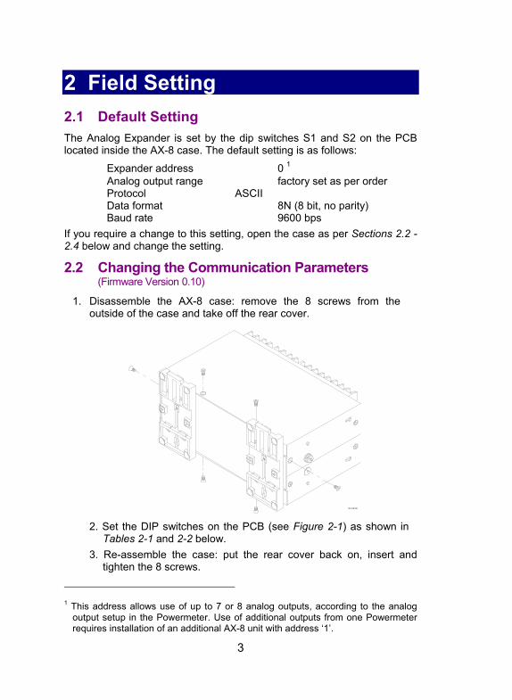
2 Field Setting 2. 2.1 Default Setting The Analog Expander is set by the dip switches S1 and S2 on the PCB located inside the AX-8 case. The default setting is as follows: Expander address 0 1 Analog output range factory set as per order Protocol ASCII Data format 8N (8 bit, no parity) Baud rate 9600 bps If you require a change to this setting, open the case as per Sections 2.2 - 2.4 below and change the setting.
2.2 Changing the Communication Parameters (Firmware Version 0.10)
1. Disassemble the AX-8 case: remove the 8 screws from the outside of the case and take off the rear cover.
2. Set the DIP switches on the PCB (see Figure 2-1) as shown in
Tables 2-1 and 2-2 below. 3. Re-assemble the case: put the rear cover back on, insert and
tighten the 8 screws.
1 This address allows use of up to 7 or 8 analog outputs, according to the analog
output setup in the Powermeter. Use of additional outputs from one Powermeter requires installation of an additional AX-8 unit with address ‘1’.

4
Figure 2-1 Location of Dip Switches on AX-8 PCB
Table 2-1 DIP Switch S1 * = default AX-8 Option SW1
Addr0 SW2
Addr1 SW3
Addr 2 SW4 N/A
SW5 N/A
SW6 SW7 SW8 Factory Set
Address 0 OFF OFF OFF Address 1 ON OFF OFF Address 2 OFF ON OFF Address 3 ON ON OFF Address 4 OFF OFF ON Address 5 ON OFF ON Address 6 OFF ON ON Address 7 ON ON ON
Table 2-2 DIP Switch S2 (Serial Port) * = default AX-8 Option SW1
Mode SW2 Data
SW3 Parity
SW4 N/A
SW5 Baud 0
SW6 Baud 1
SW7 Baud 2
SW8 Baud 3
ASCII mode OFF Binary mode (transparent)
ON
7 bit/Even parity OFF ON 8 bit/No parity ON OFF 8 bit/Even parity ON ON 110 baud OFF OFF OFF OFF 300 baud ON OFF OFF OFF 600 baud OFF ON OFF OFF 1200 baud ON ON OFF OFF 2400 baud OFF OFF ON OFF 4800 baud ON OFF ON OFF 9600 baud OFF ON ON OFF 19200 baud ON ON ON OFF
CE5R4
3
R27
R29
R28
C14 R30 1
1
C204R204
R25
R35
R38
R36+
+15V
C18
S1
R16
R18
R14
R26
R24
1
S2
+
C13
C12
D5
U6L3
R42
R101
R109
U10
2
R103
R110
R107
R108
R104R105
C101C10
2
U101
R23
D7 CE4
+
CE7
R106
D8
+
TOP PC0117 REV.A1
1 1
4 3 127 6 58
00-03008
8 67 5 34 2 1
ON ON

5
3 Installation 3.
3.1 Mechanical Installation The AX-8 should be mounted in a dirt-free environment away from heat sources and high electrical fields. Mounting may be either standard DIN rail or wall mount. Only front access is required for wiring.
4.685"(186.0)
5.118"
(130.0)
01-0
5001
-1
2 .99
2"
ANALOG EXPANDER AX-8
7.323"
(76.
0)
PANEL
(36.3)
1.430"
(165.0)
6.496"
Figure 3-1 Standard DIN Rail Mounting

6
ANALOG EXPANDER AX-8 PANEL
LOCK WASHER
SCREW
Figure 3-2 Wall Mounting
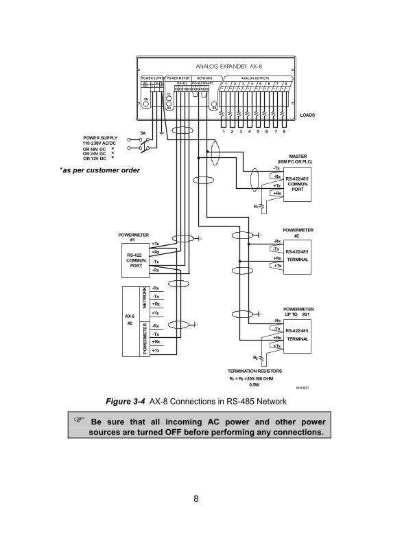
3.2 Electrical Installation For AX-8 connections to the power supply, communications and analog outputs, see Figures 3-3 (RS-422 network) or 3-4 (RS-485 network).
IMPORTANT: It is recommended to solder the wire ends before attaching them to the connectors.
Power Supply Use a dedicated breaker from a proper power source, from which the unit can be turned off. All AX-8 analog outputs are provided with an internal power supply; no external power supply for analog outputs is required. Communications The AX-8 is connected on one side to the Powermeter via the RS-422 input, and from the other side, to the multi-drop communication network via the RS422 or RS-485 output, using the ASCII, Modbus or DNP3.0 protocol.
Communications may be over a distance of up to 1000 meters and at a baud rate of up to 19,200 bps. A twisted pair cable of 0.33mm2/22AWG is recommended.

7
Analog Output Options Current output options Voltage output options 0-20mA, 4-20mA 0-10V DC and ±10V DC 0-1mA, ±1mA
Loads must be connected to analog outputs 1-8 according to their polarity.
Figure 3-3 AX-8 Connections in RS-422 Network
Be sure that all incoming AC power and other power sources are turned OFF before performing any connections.
00-03020
+Rx
-Rx
+Tx
-Tx
COMMUN.PORT
AX-8#2
POWERMETER
RS-422
(IBM PC OR PLC)MASTER
RS-422COMMUN.
PORT
#2
RS-422TERMINAL
POWERMETER
TERMINALRS-422
#31POWERMETER N
ETW
OR
KPO
WER
MET
ER
ANALOG EXPANDER AX-8
ANALOG OUTPUTS
ON
POWER SUPPLY
DCAC
+L N_
NETWORKRS-422/RS-485
RX
RS-422POWER METER
TXTX RX
++ _ _
RX
+ _1 2
RXTX RXTXRXTX__++ + _ + _ + _ + _ + _ + _ + _
OR 48V DCOR 24V DCOR 12V DC
POWER SUPPLY110-230V AC/DC
*
7653 421
**
3 4 5 6 7 8
8
LOADS
R1
#1 -Rx
-Tx
+Rx
+Tx
+Tx
+Rx
-Tx
-RxUP TO
2R
+Tx
+Rx
-Tx
-Rx
-Rx
-Tx
+Rx
+Tx
-Rx
-Tx+Rx
+Tx
TERMINATION RESISTORSR2R1 = =200-500 OHM
0.5W
5A
*as per customer order
8
Figure 3-4 AX-8 Connections in RS-485 Network
Be sure that all incoming AC power and other power sources are turned OFF before performing any connections.
*as per customer order
00-03021
+Rx
-Rx
+Tx
-Tx
COMMUN.PORT
AX-8#2
POWERMETER
RS-422/485
(IBM PC OR PLC)MASTER
RS-422COMMUN.
PORT
#2
TERMINAL
POWERMETER
TERMINAL
#31POWERMETER NE
TWOR
KPO
WER
MET
ER
ANALOG EXPANDER AX-8
ANALOG OUTPUTS
ON
PO WE R SUPPLY
DCAC
+L N_
NETW ORKRS- 422/RS-485
RX
RS- 422PO WER MET ER
TXTX RX
++ _ _
RX
+ _1 2
RXTX RXTXRXTX__++ + _ + _ + _ + _ + _ + _ + _
OR 48V DCOR 24V DCOR 12V DC
POWER SUPPLY110-230V AC/DC
*
7653 421
**
3 4 5 6 7 8
8
LOADS
R1
#1 -Rx
-Tx
+Rx+Tx
+Tx
+Rx
-Tx
-RxUP TO
2R
+Tx
+Rx
-Tx
-Rx
-Rx
-Tx+Rx
+Tx
-Rx
-Tx+Rx
+Tx
TERMINATION RESISTORSR2R1 = =200-500 OHM
0.5W
RS-422/485
RS-422/485
5A

9
4 Operation 4. Refer to the Installation and Operation Manual of the specific Powermeter for instructions on Analog Expander and communication parameters setup.
4.1 Power Up Close the power feed breaker; the ‘ON’ LED will light up.
4.2 Communication When you program your powermeter to output data to external analog outputs, the powermeter periodically updates the AX-8 analog outputs (each 300-500 ms) via the pair of wires on the RS-422 communications link used for transmitting data. At that time, the transmission (output) line of the AX-8 is disconnected from the external network, while the receive line is directly connected to the powermeter port so that the instrument is constantly ‘listening’ to the network.
When data is requested from the powermeter by a master computer (or controller), the powermeter instructs the AX-8 to switch the transmission line to the external network, and then sends the response. After the response message is sent out, the transmission line is disconnected from the network and the powermeter continues updating the AX-8 outputs.
The AX-8 can work with different ASCII and non-ASCII network protocols. If you use an ASCII communications protocol, set the switch #1 on the DIP switch block S2 to OFF in order to put the AX-8 into ASCII mode. The ASCII message frame should be ended with two characters CR/LF (ASCII 13 and 10). If you are using non-ASCII communications protocol such as Modbus or DNP 3.0, set the switch #1 on the DIP switch block S2 to ON to put the AX-8 into binary (transparent) mode. In this event, the AX-8 will not decode the message frame and the transmission line is disconnected in 3.5 character time after the response message is sent out.
Indicator LEDs The AX-8 is provided with a single Rx LED (network indication) and a pair of Rx-Tx LEDs (Powermeter indication) which operate as shown in Figure 4-1:

10
Transmission Status LED Indication no transmission no LEDs lit up Powermeter to AX-8 single Rx LED (‘1’ in Figure 4-1)
flashes RS-422: master to Powermeter Powermeter Tx LED (‘2’) flashes
Powermeter to master Powermeter Rx LED (‘3’) flashes RS-485: master to Powermeter
Powermeter to master Powermeter Rx and Tx LEDs flash
Figure 4-1 Detail of Communication LEDs on AX-8
NETWORK
RS-422/RS-485
RX
RS-422
POWER METER
TX
TX RX++ _ _
RX
+RXTX RXTXRXTX__++
1 2
3

11
5 Technical Specifications 5.
Instrument serial communications
RS-422
Network serial communications RS-422 / RS-485 Baud rate (bps) 110, 300, 600,1200, 2400, 4800,
9600, 19200 Inter-channel separation > 95dB Galvanic isolation:
Power Supply Communication
2500V rms 1000V DC
Accuracy
Temperature coefficient
±1.0% of full scale for current output up to 2500 Ω
±2.0% of full scale for current output from 2500 Ω to 10000 Ω
±50ppm/°C Resolution 8 bits Current output Span (factory set) External
resistance
Voltage output
4-20mA ± 1mA 0-20mA 0-1mA 0-10V DC ±10V DC
up to 750 Ω up to 10000 Ω up to 750 Ω up to 10000 Ω from 1000 Ω from 1000 Ω
Power supply ratings (factory set) 120&230 V AC and 110&220 V DC option 12 V DC option 24 V DC option 48 V DC
85 - 265V AC 50/60 Hz and 88 - 290V DC burden 10 W 9.6 - 19 VDC 19 - 37 VDC 37 - 72 VDC
Ambient temperature Operation: -20°C to +60°C Storage: -25°C to +80°C
Humidity 95% max. non-condensing Enclosure Aluminum, anodized Mounting 35 mm DIN rail or wall mount Weight 0.6 kg (1.32 lb.) Dimensions 186 x 75 x 109 mm (7.33 x 2.95 x
4.3 inch)

12
Technical Specifications (continued)
Standards UL File # E129258 CE-EMC: 89/336/EEC as amended by 92/31/EEC and 93/68/EEC CE-SAFETY: 72/23/EEC as amended by 93/68/EEC and 93/465/EEC
Harmonized standards to which conformity is declared: EN55011:1991; EN50082-1:1992; EN61010-1:1993; A2/1995
ANSI C37.90.1 1989 Surge Withstand Capability (SWC) ANSI C62.41 - 1991 Standard Surge EN50081-2 Generic Emission Standard - Industrial Environment EN50082-2 Generic Immunity Standard - Industrial Environment EN55022: 1994 Class A EN61000-4-2 ENV50140: 1983 ENV50204: 1995 (900MHz) ENV50141: 1993 EN61000-4-4:1995 EN61000-4-8: 1993


![Romania - SATEC Energy Metering and Billing Conference · [☐] Wednesday , 25th of May 2016 , Romania - SATEC Energy Metering and Billing Conference . [☐] Thursday , 26th of May](https://static.documents.pub/doc/80x56/5d44a5bd88c993f1188b6d94/romania-satec-energy-metering-and-billing-wednesday-25th-of-may-2016.jpg)


