DMD2401 Satellite Modem Installation and Operation Manual TM065 - Rev. 2.0 March, 1999 - NOTICE - 1999, Radyne ComStream Corporation. This manual may not in whole or in part be copied, reproduced, translated or reduced to any electronic or magnetic storage medium without the written consent of a duly authorized officer of Radyne Corporation. Radyne ComStream Corporation • 3138 E. Elwood St. • Phoenix, AZ 85034 • (602) 437-9620 • Fax: (602) 437-4811
Transcript
DMD2401Satellite Modem
Installation and Operation Manual
TM065 - Rev. 2.0
March, 1999
- NOTICE -
1999, Radyne ComStream Corporation. This manual may not inwhole or in part be copied, reproduced, translated or reduced to anyelectronic or magnetic storage medium without the written consentof a duly authorized officer of Radyne Corporation.
Radyne ComStream Corporation • 3138 E. Elwood St. • Phoenix, AZ 85034 • (602) 437-9620 • Fax: (602) 437-4811
DMD2401 Satellite Modem Warranty Policy
TM065 - Rev. 2.0 ii
Radyne ComStream Warranty Policy
Warranty and ServiceRadyne ComStream (Hereafter referred to as Radyne or Seller) warrants the items manufactured andsold by Radyne to be free of defects in material and workmanship for a period of two (2) years from dateof shipment. Radyne's obligation under its warranty is limited in accordance with the periods of time andall other conditions stated in all provisions of this warranty. This warranty applies only to defects inmaterial and workmanship in products manufactured by Radyne. Radyne makes no warrantywhatsoever concerning products or accessories not of its manufacture. Repair, or at Radyne's option,replacement of the Radyne products or defective parts therein shall be the sole and exclusive remedy forall valid warranty claims.
Warranty PeriodThe applicable warranty period shall commence on the date of shipment from Radyne's facility to theoriginal purchaser and extend for the stated period following the date of shipment. Upon beginning ofthe applicable Radyne warranty period, all customer's remedies shall be governed by the terms stated orreferenced in this warranty. In-warranty repaired or replacement products or parts are warranted only forthe remaining unexpired portion of the original warranty period applicable to the repaired or replacedproducts or parts. Repair or replacement of products or parts under warranty does not extend theoriginal warranty period.
Warranty Coverage LimitationsThe following are expressly not covered under warranty:
1. Any loss, damage and/or malfunction relating in any way to shipping, storage, accident, abuse,alteration, misuse, neglect, failure to use products under normal operating conditions, failure to useproducts according to any operating instructions provided by Radyne, lack of routine care andmaintenance as indicated in any operating maintenance instructions, or failure to use or take any properprecautions under the circumstances.
2. Products, items, parts, accessories, subassemblies, or components which are expendable in normaluse or are of limited life, such as but not limited to, bulbs, fuses, lamps, glassware, etc. Radyne reservesthe right to revise the foregoing list of what is covered under this warranty.
Warranty Replacement and AdjustmentRadyne will not make warranty adjustments for failures of products or parts which occur after thespecified maximum adjustment period. Unless otherwise agreed, failure shall be deemed to haveoccurred no more than seven (7) working days before the first date on which a notice of failure isreceived by Radyne. Under no circumstances shall any warranty exceed the period stated above unlessexpressly agreed to in writing by Radyne.
Liability LimitationsThis warranty is expressly in lieu of and excludes all other express and implied warranties, including butnot limited to warranties of merchantability and of fitness for particular purpose, use, or applications, andall other obligations or liabilities on the part of Radyne, unless such other warranties, obligations, orliabilities are expressly agreed to in writing by Radyne.
All obligations of Radyne under this warranty shall cease in the event its products or parts thereof havebeen subjected to accident, abuse, alteration, misuse or neglect, or which have not been operated andmaintained in accordance with proper operating instructions.
In no event shall Radyne be liable for incidental, consequential, special or resulting loss or damage ofany kind howsoever caused. Radyne’s liability for damages shall not exceed the payment, if any,
Warranty Policy DMD2401 Satellite Modem
TM065 - Rev. 2.0 iii
received by Radyne for the unit or product or service furnished or to be furnished, as the case may be,which is the subject of claim or dispute.
Statements made by any person, including representatives of Radyne, which are inconsistent or inconflict with the terms of this warranty, shall not be binding upon Radyne unless reduced to writing andapproved by an officer of Radyne.
Warranty Repair Return ProcedureBefore a warranty repair can be accomplished, a Repair Authorization must be received. It is at this timethat Radyne will authorize the product or part to be returned to the Radyne facility or if field repair will beaccomplished. The Repair Authorization may be requested in writing or by telephoning:
Any product returned to Radyne for examination must be sent prepaid via the means of transportationindicated as acceptable to Radyne. Return Authorization Number must be clearly marked on theshipping label. Returned products or parts should be carefully packaged in the original container, ifpossible, and unless otherwise indicated, shipped to the above address.
Non-Warranty RepairWhen a product is returned for any reason, Customer and its shipping agency shall be responsible for alldamage resulting from improper packing and handling, and for loss in transit, not withstanding any defector nonconformity in the product. By returning a product, the owner grants Radyne permission to openand disassemble the product as required for evaluation. In all cases, Radyne has sole responsibility fordetermining the cause and nature of failure, and Radyne's determination with regard thereto shall befinal.
DMD2401 Satellite Modem Record of Revisions
TM065 - Rev. 2.0 iv
DMD2401 Satellite ModemInstallation and Operation Manual
TM065 - Record of Revisions
Radyne Corporation is constantly improving its products and therefore the information in this document issubject to change without prior notice. Radyne Corporation makes no warranty of any kind with regard tothis material, including but not limited to the implied warranties of merchantability and fitness for aparticular purpose. No responsibility for any errors or omissions that may pertain to the material herein isassumed. Radyne Corporation makes no commitment to update nor to keep current the informationcontained in this document. Radyne Corporation assumes no responsibility for use of any circuitry otherthan the circuitry employed in Radyne Corporation’s systems and equipment.
RevisionLevel
Date Reason for Change
1.0 7-18-97 Preliminary Release
2.0 3-01-99 Added IBS or IDR Update information; New Interfaces Section; Updated Remote Spec
2.1.1 Removal and Assembly………………………………………………………………………………..................................................................................................................................2-1
Appendix A - DMD2401 Specifications…………………………………………………………………………… A-1
Appendix B - Remote Communications……………………………………………………………………………..B-1
Appendix C - DMD2401 Terminal Screens…………………………….. C-1
DMD2401 Universal Satellite Modem Table of Contents
TM065 - Rev. 2.0 vii
DMD2401 Satellite Modem Description
TM065 - Rev. 2.0 Page 1-1
Section One - DMD2401 Satellite Modem Description
1.0 Introduction
The Radyne Corporation DMD2401 Satellite Modem is a microprocessor-controlled Binary Phase ShiftKeyed (BPSK), Quadrature Phase Shift Keyed (QPSK), or Offset Quadrature Phase Shift Keyed (OQPSK)Modulator and Demodulator for use as part of the transmitting and receiving ground equipment in asatellite communications system. The modem is designed for service in an SCPC system where twomodems are set for continuous operation with each other. The DMD2401 Modem is referred to as the“modem” or DMD2401 throughout the remainder of this manual.
This versatile equipment package combines unsurpassed performance with numerous user-friendly frontpanel programmable functions. The DMD2401 provides selectable functions for Intelsat IBS/IDR, as wellas closed networks. All of the configuration, monitor, and control functions are available at the front panel.Operating parameters such as variable data rates, FEC code rate, IF frequencies and IBS/IDR framing canbe readily set and reconfigured from the front panel by earth station operations personnel. Additionally, allfunctions can be accessed with a terminal or personal computer via a serial link for complete remotemonitor and control capability.
The DMD2401 operates at all standard IBS and IDR data rates up to 4.375 Mbps. Selection of any datarate in closed network operation is provided over the range of 9.6 Kbps to 4.375 Mbps in 1 bps steps. Themaximum symbol rate is 2.5 Msps, regardless of modulation type, FEC, code rate or framing type.
The DMD2401 is designed to perform as both ends of a satellite Single Channel Per Carrier (SCPC) link oras the VSAT remote site modem in a TDMA hub system. The DMD2401 can be used in mesh or startopology networks. The Modulator and Demodulator operate independently using BPSK, QPSK or OQPSKmodulation in either SCPC or VSAT modes.
The DMD2401 is also the ideal VSAT modem for use in a point-to-point frame relay hybrid network. Otherapplications include FDMA, telephony, video conferencing, long-distance learning, paging and newsgathering.
Selection of any data rate is provided over the following ranges:
The DMD2401 is programmable from the front panel. The program menu was specifically designed forease of use to quickly put the modem online and for any network changes. The modem also can bemonitored and controlled through the RS485 or RS232 serial control channel.
The DMD2401 can track and acquire a carrier over a programmable range of ±1 KHz to ±42 KHz.Acquisition times of less than 10 seconds are typical at data rates of 64 Kbps over a range of ±255 KHz.
To facilitate link testing, the DMD2401 incorporates a built-in ‘2047’ test pattern generator with BERmeasurement capability. A user-selectable terrestrial and/or satellite loopback test capability is alsoprovided.
For applications requiring systems redundancy, the DMD2401 modem may be used with the RadyneRCS11 1:1 Redundancy Switch or the RCS20 M:N (N<9) Redundancy Switch. A full range of industry-standard interfaces are available for the DMD2401. These include RS232, V.35, RS422/449 and ITUG.703.
Description DMD2401 Satellite Modem
Page 1-2 TM065 - Rev. 2.0
Available options for the DMD2401 include a low data rate asynchronous serial overhead channel forremote monitor and control. Additionally, a Sequential codec is available for applications requiringcompatibility with existing systems.
Figure 1-1. DMD2401 Satellite Modem Front Panel
1.1 DMD2401 Available Options
A wide range of options are available for the DMD2401 Satellite Modem. A brief description of eachfollows:
1.1.2 Reed-Solomon Codec
The DMD2401 can be equipped with a Reed-Solomon outer codec with an interleaver as an optionalenhancement. The encoder and decoder are completely independent and meet the IESS-308/309specification. Once prepped, this option can be installed in the field by installing four IC’s into existingsockets. The DMD2401 must be prepped for this option.
NOTE: Custom Reed-Solomon codes are also available.
1.1.3 Sequential Decoding
The DMD2401 can also be equipped with a sequential decoder that can be installed as an option. TheDMD2401 must be prepped for this option in the factory. Once prepped, the option can be added byinstalling an IC into an existing socket. Sequential Encoding/Decoding can operate with Rate 1/2, 3/4, and7/8 up to data rates of 4.375 Mbps.
1.1.4 Asynchronous Overhead Channel
The DMD2401 can be equipped with an asynchronous overhead channel capability as an option. Theoption can be added in the field by installing a single interface PC board. The overhead channel isproportional to the data rate (approximately 1200 baud per 64 Kbps) up to a maximum of 19.2 K baud.
DMD2401 Satellite Modem Description
TM065 - Rev. 2.0 Page 1-3
1.1.5 Customized Options
The DMD2401 may be customized for specific customer requirements. Most modifications/customizationcan be accomplished by means of firmware/software modifications.
The following are examples of the types of customization available to the user:
• Customized Data Rates.
• Customized Scrambler/Descramblers.
• Customized Overhead Framing Structures.
• Customized Modulation Formats.
• Customized Uses for Asynchronous Overhead Channel.
• All customer inquiries are welcome.
1.2 DMD2401 Functional Block Diagram
Figure 1-2 represents the DMD2401 Functional Blocks. The modem is shown in a typical application withcustomer data, Tx/Rx RF equipment and an antenna.
Description DMD2401 Satellite Modem
Page 1-4 TM065 - Rev. 2.0
DMD2401 Satellite Modem Description
TM065 - Rev. 2.0 Page 1-5
1.3 ApplicationsFollowing are just a few representative forms of satellite communication links and networks in which theDMD2401 modem may be used.
1.3.1 SCPC Point-to-Point Links
The most straightforward application for a satellite modem is to serve as the Data CommunicationsEquipment (DCE) for a point-to-point data link. When used in this mode, two modems located at twodifferent sites are tuned to complementary transmit and receive frequencies. Each direction of thecommunications link may have the same or entirely different transmission parameters. In this application, itis typical that the link is established and maintained on a continuous basis, although a special “on demand”case is described later.
1.3.2 SCPC Point to Multi–Point Links in a Broadcast Application
A broadcast application might involve the necessity of sending continuous or intermittent data from onesource and “broadcasting” the information to many remote locations. For instance, constant pricinginformation and updates may be sent by a central location to many store locations. There may be minorreturn information from the remotes acknowledging receipt.
Another broadcast application could be transmitting background music from a central location to manystore sites. In this case, there would be no return path.
The topology of the network in both of these broadcast examples would typically be called a “Star” network.As shown in Figure 1-3, the shape of the configuration is drawn with the central “Hub” as the center of thestar and the remotes as points of the star. In both cases the transmit frequency and other parameters areshared by the receiver of all the remotes.
1.3.3 DAMA (Demand Assigned Multiple Access)
Suppose that we wanted to simulate a telephone network with a virtual switch between modems carryingdigitized voice information. We might use a central computer to assign a pair of frequencies for anyconversation and send this connection information to the proper sites to set up the connection. In thisapplication, a new network configuration is usable. That is a “Mesh” network where any of the voicemodems at any site can be programmed to link with any other modem. The resulting link diagram lookslike a mesh of interconnects.
Since the frequencies can be assigned on demand, the network is then called “Demand Assigned, Multiple
Figure 1-3. Star Network Configuration
Hub
RemoteC
RemoteE
RemoteD
RemoteA
RemoteB
Description DMD2401 Satellite Modem
Page 1-6 TM065 - Rev. 2.0
Access,” or DAMA.
1.3.4 TDMA (Time Division Multiple Access) Remote Site Application
In a TDMA network, the central Hub continually transmits a stream of outbound data containing informationfor multiple remote sites, while the remote sites transmit back to the Hub on a timed basis. Each of theseremotes is said to “burst” its information back on a specific frequency. This may be the same inboundfrequency for all sites. Each of the remotes is responsible for accessing its own information from theoutbound data stream by reading the address assigned to specific parts of the data. The TDMA networkusually looks like the Star network shown in Figure 1-3.
The DMD2401 is specifically designed to be usable as the remote site modem of a TDMA network whencoupled with a proper “Burst” demodulator at the hub site.
DMD2401 Satellite Modem Installation
TM065 - Rev. 2 Page 2-1
Section 2 - Installation
2.0 Installation Requirements
The DMD2401 Modem is designed to be installed within any standard 19-inch wide equipment cabinet orrack, and requires 1 RU mounting space (1.75 inches) vertically and 21-inches of depth. Includingcabling, a minimum of 23-inches of rack depth is required. The rear panel of the DMD2401 is designed tohave power enter from the left and IF cabling enter from the right when viewed from the rear of themodem. Data and control cabling can enter from either side although they are closer to the left. The unitcan be placed on a table or suitable surface if required.
There are no user-serviceable parts or configuration settings located inside the DMD2401chassis. There is a potential shock hazard internally at the power supply module. DO NOT openthe modem case.
⇒⇒ CAUTION: Before initially applying power to the modem, it is a good idea to disconnect thetransmit output from the operating satellite ground station equipment. This is especially true if thecurrent modem configuration settings are unknown, where incorrect setting could disrupt existingcommunications traffic.
2.1 Unpacking
The DMD2401 Modem was carefully packaged to avoid damage and should arrive complete with thefollowing items for proper installation:
1. DMD2401 Modem Unit.
2. Power Cord, 6-foot with applicable AC connector.
3. Installation and Operation Manual.
2.1.1 Removal and AssemblyIf using a knife or cutting blade to open the carton, exercise caution to ensure that the blade does notextend into the carton, but only cuts the tape holding the carton closed. Carefully unpack the unit andensure that all of the above items are in the carton. If the Prime AC power available at the installationsite requires a different power cord/AC connector, then arrangements to receive the proper device willbe necessary before proceeding with the installation.
The DMD2401 Modem unit is shipped fully-assembled and does not require removal of the covers forany purpose in installation. Always ensure power is removed from the DMD2401 before removing orinstalling a UIM. Should the power cable AC connector be of the wrong type for the installation, eitherthe cable or the power connector end should be replaced. The power supply itself is designed foruniversal application using from 100 to 240 Vac, 50-60 Hz, 1.0 A.
2.2 Mounting Considerations
When mounted in an equipment rack, adequate ventilation must be provided. The ambient temperaturein the rack should preferably be between 10° and 35° C, and held constant for best equipment operation.The air available to the rack should be clean and relatively dry. The modem units may be stacked one ontop of the other to a maximum of 10 consecutive units before providing a 1 RU space for circulation.Modem units should not be placed immediately above a high heat or EMF generator to ensure the outputsignal integrity and proper receive operation.
Installation DMD2401 Satellite Modem
Page 2-2 TM065 - Rev. 2.0
DMD2401 Satellite Modem Installation
TM065 - Rev. 2.0 Page 2-3
Installation DMD2401 Satellite Modem
Page 2-4 TM065 - Rev. 2.0
DMD2401 Satellite Modem Installation
TM065 - Rev. 2.0 Page 2-5
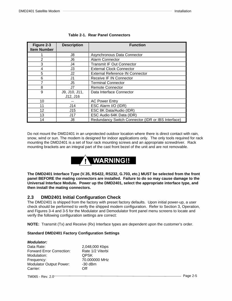
Table 2-1. Rear Panel Connectors
Figure 2-3Item Number
Description Function
1 J8 Asynchronous Data Connector2 J6 Alarm Connector3 J4 Transmit IF Out Connector4 J3 External Clock Connector5 J2 External Reference IN Connector6 J1 Receive IF IN Connector7 J5 Terminal Connector8 J7 Remote Connector9 J9, J10, J11,
J12, J16Data Interface Connector
10 -- AC Power Entry11 J14 ESC Alarm I/O (IDR)12 J15 ESC 8K Data/Audio (IDR)13 J17 ESC Audio 64K Data (IDR)14 J8 Redundancy Switch Connector (IDR or IBS Interface)
Do not mount the DMD2401 in an unprotected outdoor location where there is direct contact with rain,snow, wind or sun. The modem is designed for indoor applications only. The only tools required for rackmounting the DMD2401 is a set of four rack mounting screws and an appropriate screwdriver. Rackmounting brackets are an integral part of the cast front bezel of the unit and are not removable.
The DMD2401 Interface Type (V.35, RS422, RS232, G.703, etc.) MUST be selected from the frontpanel BEFORE the mating connectors are installed. Failure to do so may cause damage to theUniversal Interface Module. Power up the DMD2401, select the appropriate interface type, andthen install the mating connectors.
2.3 DMD2401 Initial Configuration CheckThe DMD2401 is shipped from the factory with preset factory defaults. Upon initial power-up, a usercheck should be performed to verify the shipped modem configuration. Refer to Section 3, Operation,and Figures 3-4 and 3-5 for the Modulator and Demodulator front panel menu screens to locate andverify the following configuration settings are correct:
NOTE: Transmit (Tx) and Receive (Rx) Interface types are dependent upon the customer’s order.
To lock up the modem, turn the carrier ON, enter ‘IF Loopback Enable,’ or connect a loopback cablefrom J1 to J2 on the rear panel of the modem.
2.4 Modem Connections/Interface Connectors
All modem connections are made to the labeled connectors located on the rear of the unit. Theconnector definitions and pinout tables are shown below, and are those on the modem unit. Anyconnection interfacing to the modem must be the appropriate mating connector.
NOTE: Shielded cables with the shield terminated to conductive backshells are required in order to meetEMC directives. Cables with insulation flammability ratings of 94 VO or better are required for LowVoltage Directives.
2.4.1 DMD2401 Connector Pinout TablesThe types and pinouts of the rear panel connectors vary by the type of interface installed. Descriptionsand pinouts for all rear panel connectors for each of the available interfaces are described in Chapter 5,Interfaces.