34
1 © 813776 Installation and Operations Manual Siemens VersiCharge™
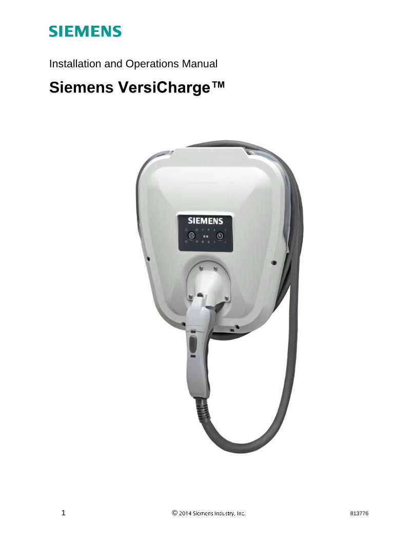
1 © 813776
Installation and Operations Manual
Siemens VersiCharge™
2 © 813776
Contact Information
Siemens Industry, Inc. Infrastructure & Cities Sector Low and Medium Voltage 5400 Triangle Parkway Norcross, GA 30092
1-800-241-4453 www.usa.siemens.com/versicharge [email protected]
FCC Compliance
This equipment has been tested and found to comply with the limits for a Class B digital device, pursuant to part 15 of the FCC Rules. These limits are designed to provide reasonable protection against harmful interference in a residential installation. This equipment generates, uses and can radiate radio frequency energy and, if not installed and used in accordance with the instructions, may cause harmful interference to radio communications. However, there is no guarantee that interference will not occur in a particular installation. If this equipment does cause harmful interference to radio or television reception, which can be determined by turning the equipment off and on, the user is encouraged to try to correct the interference by one or more of the following measures:
Reorient or relocate the receiving antenna.
Increase the separation between the equipment and the receiver.
Connect the equipment into an outlet on a circuit different from that to which the receiver is connected.
Consult the dealer or an experienced radio/TV technician for help.
Changes or modifications not expressly approved by the party responsible for compliance may void the user’s authority to operate the equipment and the warranty on the product.
Other Information
Product information is subject to change without notice. All trademarks are recognized as the property of their respective owners. For Siemens VersiCharge™ Warranty Terms and Conditions, see the Appendix on page 29 of this manual.
© 2014 Siemens Industry, Inc. All rights reserved.
3 © 813776
Table of Contents 1 Important Safety Information ................................................................................................... 5
1.1 Read this First .................................................................................................................. 5
1.2 Symbol Legend................................................................................................................. 5
1.3 Product Labels.................................................................................................................. 5
1.4 Definitions ......................................................................................................................... 6
1.5 Safety Instructions (General and Specific) ........................................................................ 6
1.6 Instructions Pertaining to a Risk of Fire or Electric Shock ................................................. 6
1.7 Code and Standard References ....................................................................................... 7
2: Device Layout ........................................................................................................................ 9
2.1 Exterior – Front ................................................................................................................. 9
2.2 Exterior – LED Indicators .................................................................................................. 9
2.3 Mounting Bracket (Receptacle not Included) ...................................................................10
2.4 Exterior – Rear ................................................................................................................11
2.5 Interior – Connection Area ...............................................................................................12
2.6 Device States ..................................................................................................................13
Section 3: Installation ................................................................................................................14
3.1 Building Survey................................................................................................................14
3.2 Site Selection ..................................................................................................................14
3.3 Cord-and-plug installation (UNIVERSAL UNITS) .............................................................15
3.4 Hard-wired installation (UNIVERSAL/HARDWIRED UNITS) ............................................18
3.5 Amperage Adjustment .....................................................................................................21
3.6 Remote Control Interface .................................................................................................22
Section 4: Operation .................................................................................................................24
4.1 Overview .........................................................................................................................24
4.2 Typical Operation ............................................................................................................24
4.3 Faults ..............................................................................................................................24
4.4 Cord Management ...........................................................................................................25
4.5 Delay Timer .....................................................................................................................26
4.6 Halo Operation ................................................................................................................26
4.7 Remote Control Interface .................................................................................................27
Section 5: Troubleshooting .......................................................................................................29
5.1 General Settings ..............................................................................................................29
5.2 Specific Errors and Actions ..............................................................................................29
Section 6: Warranty ..................................................................................................................30
Section 7: Wiring Diagrams .......................................................................................................33

4 © 813776
5 © 813776
1 Important Safety Information
1.1 Read this First
This manual contains important instructions for use during installation and maintenance of the Siemens VersiCharge™ electric vehicle charging station.
1.2 Symbol Legend
To reduce the risk of electrical shock, and to ensure the safe installation and operation of the Siemens VersiCharge™, the following safety symbols appear throughout this document to indicate dangerous conditions and important safety instructions.
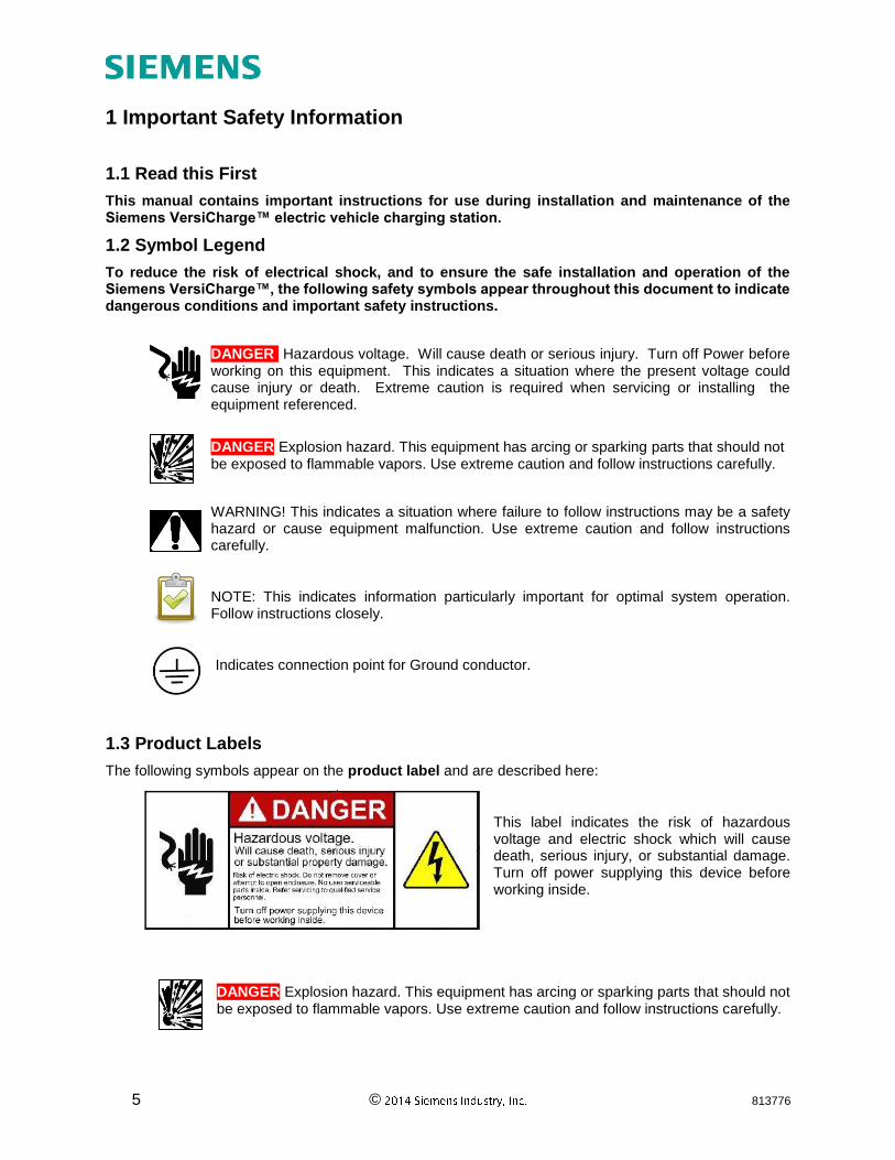
DANGER Hazardous voltage. Will cause death or serious injury. Turn off Power before working on this equipment. This indicates a situation where the present voltage could cause injury or death. Extreme caution is required when servicing or installing the equipment referenced.
DANGER Explosion hazard. This equipment has arcing or sparking parts that should not be exposed to flammable vapors. Use extreme caution and follow instructions carefully.
WARNING! This indicates a situation where failure to follow instructions may be a safety hazard or cause equipment malfunction. Use extreme caution and follow instructions carefully.
NOTE: This indicates information particularly important for optimal system operation. Follow instructions closely.
Indicates connection point for Ground conductor.
1.3 Product Labels
The following symbols appear on the product label and are described here:
This label indicates the risk of hazardous voltage and electric shock which will cause death, serious injury, or substantial damage. Turn off power supplying this device before working inside.
DANGER Explosion hazard. This equipment has arcing or sparking parts that should not be exposed to flammable vapors. Use extreme caution and follow instructions carefully.
6 © 813776
Indicates connection point for Ground conductor.
1.4 Definitions
The term EV used in this manual refers to an electric vehicle.
The term AC used in this manual refers to alternating current.
The term Universal unit refers to any VersiCharge with a plug and chord assembly attached, i.e. part numbers VC30XXXU**** (Indoor / Outdoor Use)
The term Hardwired unit refers to any VersiCharge which is factory configured for hardwired installation only, i.e. part numbers VC30XXXHW**** (Indoor Use only)
The placeholder ‘XXX’ in the mentioned part numbers can either stand for ‘GRY’ which denotes that the unit is grey or ‘BLK’ which denotes that the unit is black.
1.5 Safety Instructions (General and Specific)
DANGER Hazardous voltage. Will cause death or serious injury. Turn off Power supplying this equipment before working inside
- Read this Installation and Operations Manual in its entirety prior to installing, maintaining, servicing or replacing a Siemens VersiCharge EV Charging System.
- Permits: Be aware that many areas require special permits and/or utility approvals to install EV charging equipment. Contact your local electrical inspector’s office and your local utility prior to beginning work to understand local requirements.
- Qualified person: Because of the inherent dangers of electricity, only a qualified person should install, maintain, service, or replace electrical wiring and connected equipment. For the purpose of this manual, a qualified person is one who is familiar with the installation, construction of operation of the equipment and the hazards involved. In addition, this person should meet the definition of a qualified person pursuant to the National Electrical Code® (NEC®)1. Failure to comply with the recommendation of having a qualified person install the unit when electrical work is required may void the warranty provided with this device.
- Weatherproof seals: HARDWIRED UNITS are for indoor use only. These devices have no gaskets or seals. UNIVERSAL UNITS may be used indoors and outdoors.
WARNING! Failure to properly seat seals can result in water, debris and other foreign objects entering into the device. These can cause damage to electrical components and prevent the device from functioning properly.
1.6 Instructions Pertaining to a Risk of Fire or Electric Shock
WARNING! When using electric products, basic precautions should always be followed, including the following. This manual contains important instructions for Universal and Hardwired Units that shall be followed during installation, operation and maintenance of the unit: - Read all of the instructions before using this product.
1 National Electrical Code and NEC are Registered Trademarks of the National Fire Protection Association (NFPA)
7 © 813776
- Failure to follow these instructions may lead to death, serious injury or property damage.
- Any electrical wiring required to install this device shall conform to applicable codes and standards (ANSI/NFPA 70). A qualified electrician is recommended to perform these tasks.
- To reduce the risk of electric shock, never service, install or uninstall this device from service while energized.
- This equipment has arcing or sparking parts that should not be exposed to flammable vapors. This equipment should be located at least 18 inches above the floor.
- This device is equipped with an auto reset feature o If this device is connected to a vehicle at the time that power is restored
following an outage, charging may automatically resume. o If this device is connected to a vehicle and a ground fault trip occurs, charging
may automatically resume after a delay period. - This device should be supervised when used around children. - Do not put fingers into the electric vehicle connector. - Do not use this product if the flexible power cord or EV cable is frayed, has broken
insulation, or any other signs of damage. - Do not use this product if the enclosure or the EV connector is broken, cracked, open,
or shows any other indication of damage. - A torque driver shall be used to make power connections to ensure that adequate
contact pressure is applied. See the installation section of this manual for additional details.
- A device provided with a wire connector for field installed wiring shall be provided with instructions specifying that the connector provided shall be used in making the field connection.
- When installing this device in the hard wired configuration, power connections shall be made at line terminals with 14.5in.-lbs. torque.
- An insulated grounding conductor that is identical in size, insulation material, and thickness to the grounded and ungrounded branch-circuit supply conductors, except that it is green with or without one or more yellow stripes, shall be installed as part of the branch circuit that supplies the device or system.
- The grounding conductor shall be grounded to earth at the service equipment or, when supplied by a separately derived system, at the supply transformer.
- Do not attempt to operate this device if the ambient temperature is greater than 50C(122F)
- Use 6-8 AWG, 75C copper wire to connect to supply circuit. - CAUTION: To reduce the risk of fire, connect only to a circuit provided with 40 amperes
maximum branch circuit overcurrent protection in accordance with the ANSI/NFPA 70 National Electrical Code.
1.7 Code and Standard References
- This device has been designated to meet the requirements in section 626 of the National Electric Code (NEC®).
- UL Listing with Listing Number – Siemens VersiCharge Devices are listed in UL file # E348556
- Complies with the following UL Standards: 2594, 2231-1, 2231-2 - EV interface compliant to SAE J-1772 Level II - This equipment has been tested and found to comply with the limits for a Class B
digital device, pursuant to part 15 of the FCC Rules. These limits are designed to provide reasonable protection against harmful interference in a residential installation. This equipment generates, uses and can radiate radio frequency energy and, if not installed and used in accordance with the instructions, may cause harmful interference to radio communications. However, there is no guarantee that
8 © 813776
interference will not occur in a particular installation. If this equipment does cause harmful interference to radio or television reception, which can be determined by turning the equipment off and on, the user is encouraged to try to correct the interference by one or more of the following measures: o Reorient or relocate the receiving antenna. o Increase the separation between the equipment and receiver. o Connect the equipment into an outlet on a circuit different from that to which the
receiver is connected. o Consult the dealer or an experienced radio/TV technician for help.
- Personal Protection Equipment: Use of proper personal protection equipment, including, but not limited to, eye protection, shock protection, gloves and other appropriate protection, is recommended when installing or servicing any electrical equipment
- Charging Circuit Interrupting Device (CCID): The Siemens VersiCharge line of EV Charging Systems includes a Charging Circuit Interrupting Device (CCID). The CCID is required by UL Standard 2231 and is designed to detect grounding faults within the system, and disconnect power from the downstream conductors when a fault is detected.
- Arcing component in contactor: Siemens VersiCharge EV Charging Systems
include a contactor that, when opened or closed, will cause a short duration arc. The
contactor is enclosed in an appropriate electrical enclosure, but caution if this arc
occurs in the presence of flammable vapors, the vapors could ignite, creating an
explosion. Store flammable vapors away from all electrical equipment, and should
vapors be present, allow sufficient time for ventilation before operating this
equipment.
should be taken when servicing.
DANGER Explosion hazard. This equipment has arcing or sparking parts that should
not be exposed to flammable vapors. This equipment should be installed at least 18 inches above floor or ground level. Use extreme caution and follow instructions carefully.
9 © 813776
2: Device Layout
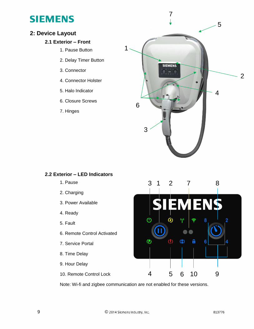
2.1 Exterior – Front
1. Pause Button
2. Delay Timer Button
3. Connector
4. Connector Holster
5. Halo Indicator
6. Closure Screws
7. Hinges
2.2 Exterior – LED Indicators
1. Pause
2. Charging
3. Power Available
4. Ready
5. Fault
6. Remote Control Activated
7. Service Portal
8. Time Delay
9. Hour Delay
10. Remote Control Lock
Note: Wi-fi and zigbee communication are not enabled for these versions.
2
1
3
4
5
6
7
1 3 2
4 5
8
9
7
10 6
10 © 813776
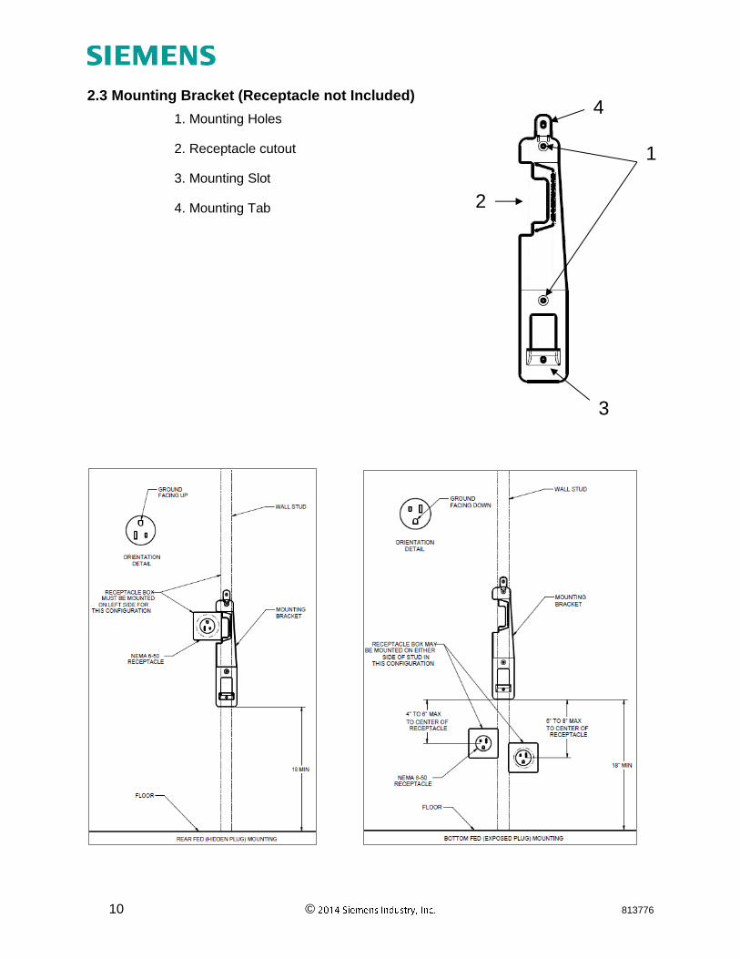
2.3 Mounting Bracket (Receptacle not Included)
1. Mounting Holes
2. Receptacle cutout
3. Mounting Slot
4. Mounting Tab
1
3
2
4
11 © 813776
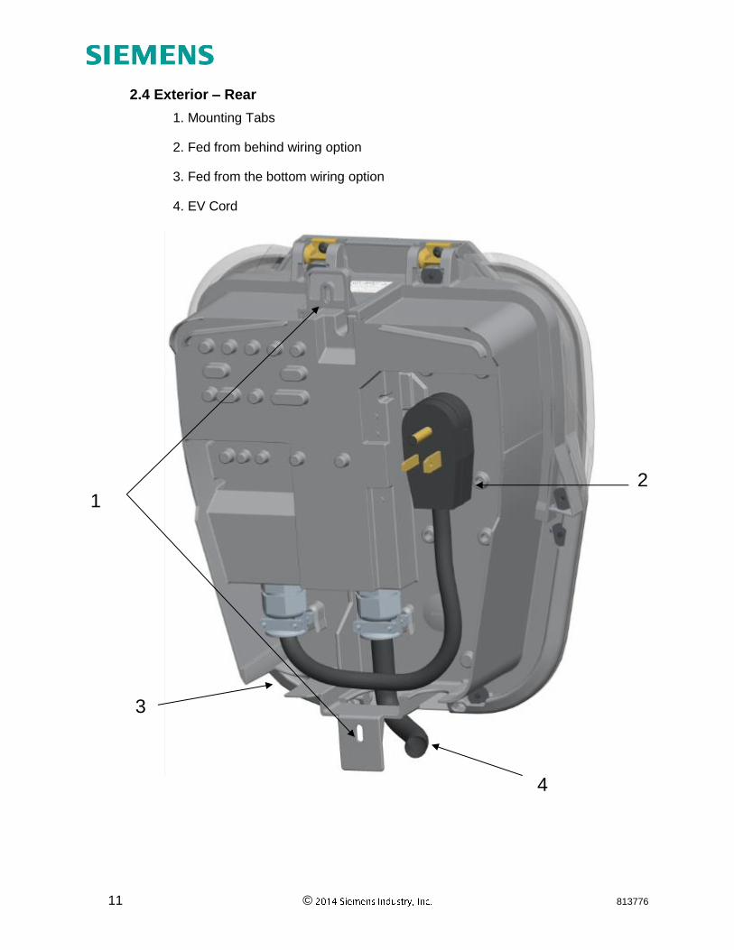
2.4 Exterior – Rear
1. Mounting Tabs
2. Fed from behind wiring option
3. Fed from the bottom wiring option
4. EV Cord
3
2 1
4
12 © 813776
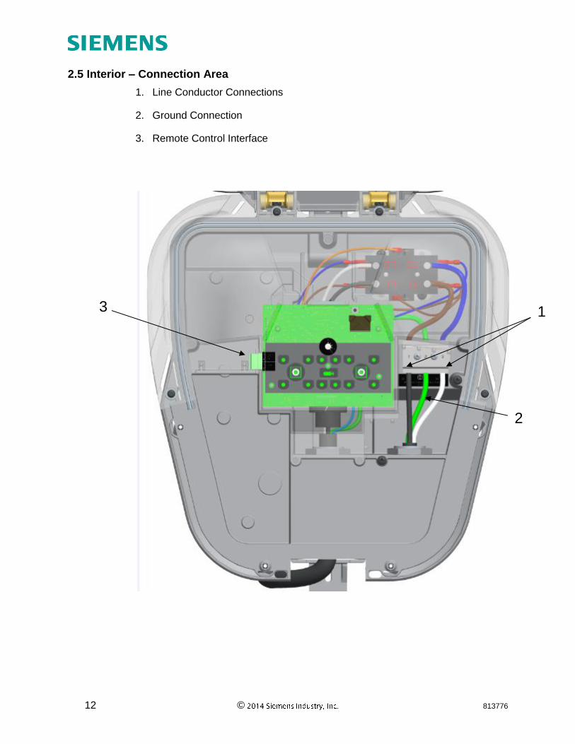
2.5 Interior – Connection Area
1. Line Conductor Connections
2. Ground Connection
3. Remote Control Interface
1
2
3
13 © 813776
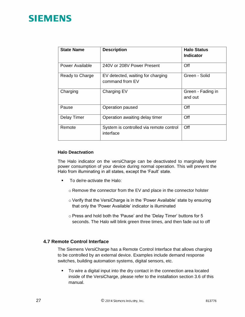
2.6 Device States
EVSE's do not have the capability to determine whether your car has been charged or not, refer to car manual for indication of car battery status.
State
Name
Description Indicator(s) Halo Status
Indicator
Power
Available
240V or 208V Power Present 'Power Available' Off
Ready to
Charge
EV detected, waiting for
charging command from EV
'Power Available' and "Ready Green - Solid
Charging Charging EV 'Power Available' and
'Charging'
Green - Fading
in and out
Pause* Operation paused 'Power Available" and
"Pause"
Off
Delay
Timer
Operation awaiting delay
timer
'Power Available' and 'Hour(s)
Delay'
Off
Remote System is controlled via
remote control interface
'Power Available' and
‘Remote Control Lock'
Off
* Some EV’s may initiate a delay of charge when exiting out of the ‘Pause’ state before the EV starts
telling the VersiCharge to start charging again. Please refer to the user manual for the EV for further
information.
Further combinations of indicators on the unit are described in the Fault code section 4.3.
14 © 813776
Section 3: Installation
3.1 Building Survey
• Available voltage, current and frequency:
VersiCharge EV charging stations can draw up to 30A at 240 VAC, 50/60
Hz (7.2kW of power). The complete electrical structure of the building must
be adequately sized to handle the entire building energy load, under peak
conditions, as well as the charging station load under operation.
Checking for adequate power includes all the connections from the utility
through the entire circuit structure to the branch circuit position and
connected wiring.
Utility connection and transformer capacity - check with utility service
provider to ensure enough power is available for the building and the
VersiCharge under full loading.
• Available breaker positions and amperage
Verify the panel has an open position for a two pole breaker.
Verify that the additional 30 A draw from the VersiCharge will not exceed
the total loading for the Main Breaker of the structure.
• Breaker selection
A 2-pole, 40 A dedicated branch breaker is required for both cord-and-plug
installation and hard wired installations. Siemens Part numbers: Q240
(plug-in type), B240 (bolt-on type).
The VersiCharge must be wired on a dedicated circuit, with no other loads
wired on that circuit.
3.2 Site Selection
NOTE: To ensure optimal functionality, we don’t recommend installing the VersiCharge unit in the direct sunlight.
NOTE: UNIVERSAL UNITS may be installed in environments in which NEMA 3R ratings are required, while HARDWIRED UNITS may only be installed in environments where NEMA 1 ratings are required.
Accessibility
When selecting a mounting site, ensure that the connector can reach the
EV before starting installation.
15 © 813776
The VersiCharge will mount on the surface of the wall, protruding at least
15 inches, and a location for installation should be chosen where there is
sufficient space to park an EV, walk past the device, open nearby doors,
etc., without obstruction.
If the installation location is not already wired for installation, installation of
the VersiCharge unit should be planned with an electrician and then the
electrician should bring in the electricity according to those guidelines.
DANGER Explosion hazard. This equipment has arcing or sparking parts that should not be exposed to flammable vapors. This equipment should be installed at least 18 inches above floor or ground level. Use extreme caution and follow instructions carefully.
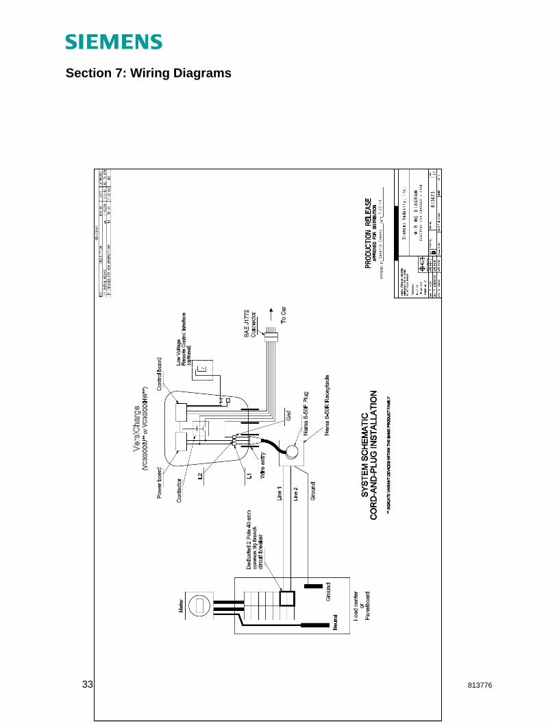
3.3 Cord-and-plug installation (UNIVERSAL UNITS)
The standard VersiCharge unit (UNIVERSAL UNIT) arrives factory-configured for rear fed and bottom fed cord-and-plug installations. Do not remove the cord as it should not be reinstalled once removed.
WARNING! Due to risk of moisture, cord-and-plug installations require a NEMA outdoor rated receptacle and enclosure, when installed outdoors. Installing outdoors without properly rated outdoor receptacles and enclosures will violate listings and void the device warranty. Outdoor cord-and-plug installations must be bottom fed only. Bottom-fed, Cord-and-Plug Installation
Mounting
Measure the plug in cord of the unit first since the mounting bracket and the
receptacle need to be located within this distance of each other.
Locate a stud within the wall to attach the mounting bracket.
o For concrete or masonry walls, install appropriate anchors.
o Verify that the stud or anchor and surrounding materials can handle the
20+ lbs load of the VersiCharge.
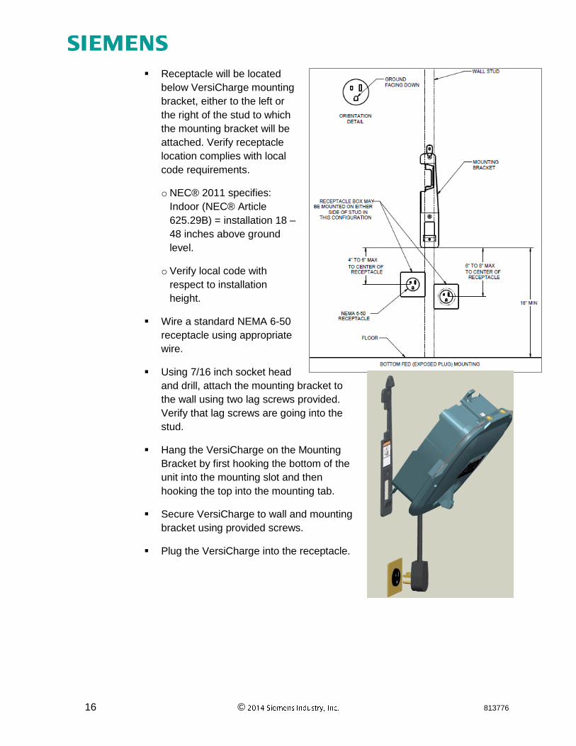
16 © 813776
Receptacle will be located
below VersiCharge mounting
bracket, either to the left or
the right of the stud to which
the mounting bracket will be
attached. Verify receptacle
location complies with local
code requirements.
o NEC® 2011 specifies:
Indoor (NEC® Article
625.29B) = installation 18 –
48 inches above ground
level.
o Verify local code with
respect to installation
height.
Wire a standard NEMA 6-50
receptacle using appropriate
wire.
Using 7/16 inch socket head
and drill, attach the mounting bracket to
the wall using two lag screws provided.
Verify that lag screws are going into the
stud.
Hang the VersiCharge on the Mounting
Bracket by first hooking the bottom of the
unit into the mounting slot and then
hooking the top into the mounting tab.
Secure VersiCharge to wall and mounting
bracket using provided screws.
Plug the VersiCharge into the receptacle.
17 © 813776
Rear-fed, Cord-and-Plug Installation
Mounting
NOTE: Flush mount installations
only, meaning the receptacle is
even with wall in which it is
installed.
Locate a stud within the
wall to attach the mounting
bracket.
o For concrete or masonry
walls, install appropriate
anchors.
o Verify that the stud or
anchor and surrounding
materials can handle the
20+ lbs load of the
VersiCharge.
Ensure that receptacle can
be flush mount installed to
the left side of the
mounting bracket.
o Receptacle should be
installed prior to
mounting the
VersiCharge to the wall.
o Verify local code with
respect to installation height.
18 © 813776
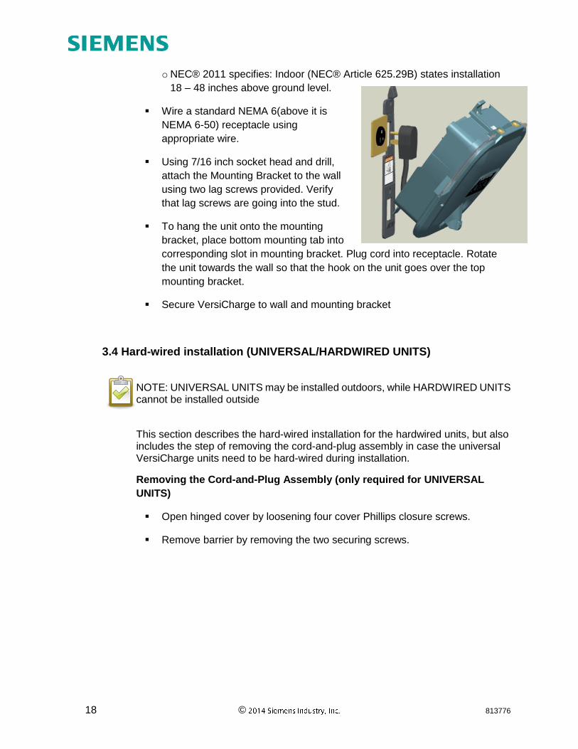
o NEC® 2011 specifies: Indoor (NEC® Article 625.29B) states installation
18 – 48 inches above ground level.
Wire a standard NEMA 6(above it is
NEMA 6-50) receptacle using
appropriate wire.
Using 7/16 inch socket head and drill,
attach the Mounting Bracket to the wall
using two lag screws provided. Verify
that lag screws are going into the stud.
To hang the unit onto the mounting
bracket, place bottom mounting tab into
corresponding slot in mounting bracket. Plug cord into receptacle. Rotate
the unit towards the wall so that the hook on the unit goes over the top
mounting bracket.
Secure VersiCharge to wall and mounting bracket
3.4 Hard-wired installation (UNIVERSAL/HARDWIRED UNITS)
NOTE: UNIVERSAL UNITS may be installed outdoors, while HARDWIRED UNITS cannot be installed outside
This section describes the hard-wired installation for the hardwired units, but also includes the step of removing the cord-and-plug assembly in case the universal VersiCharge units need to be hard-wired during installation.
Removing the Cord-and-Plug Assembly (only required for UNIVERSAL
UNITS)
Open hinged cover by loosening four cover Phillips closure screws.
Remove barrier by removing the two securing screws.
19 © 813776
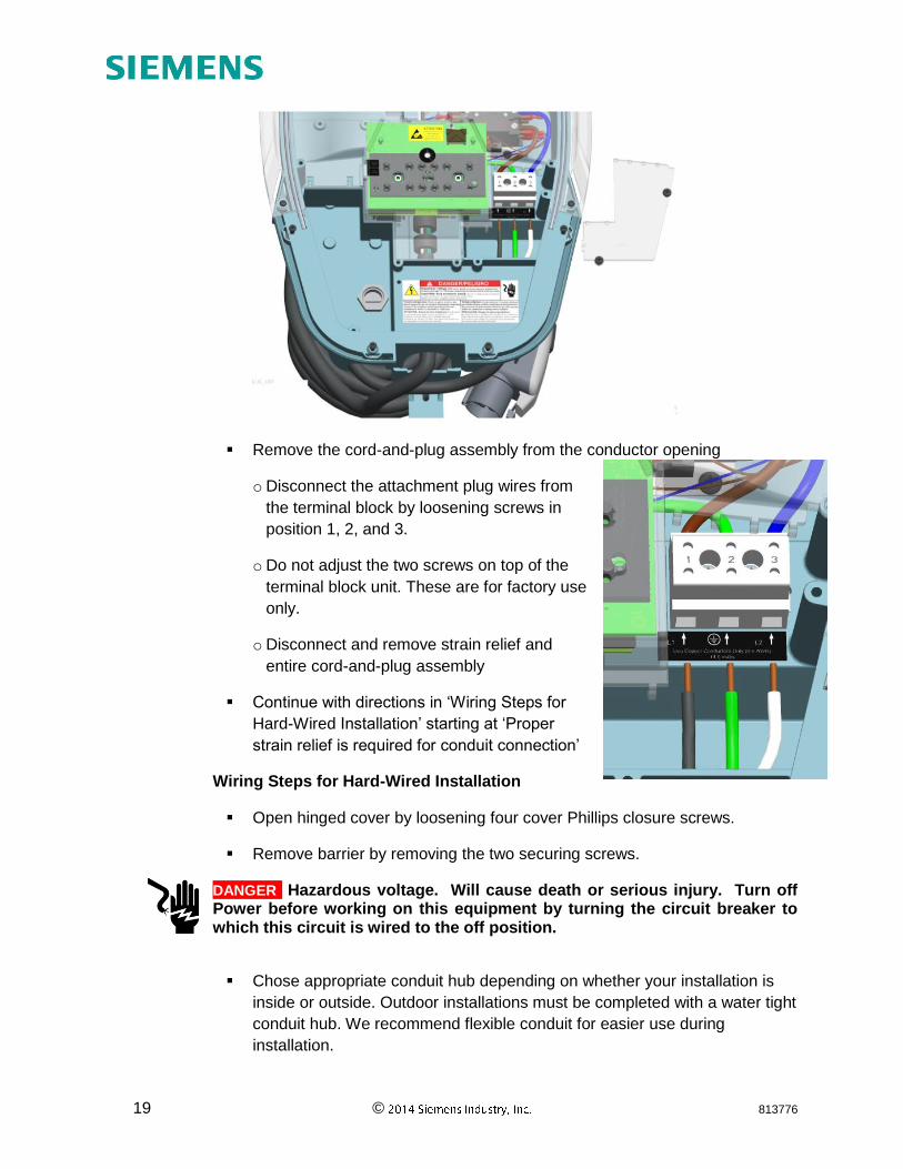
Remove the cord-and-plug assembly from the conductor opening
o Disconnect the attachment plug wires from
the terminal block by loosening screws in
position 1, 2, and 3.
o Do not adjust the two screws on top of the
terminal block unit. These are for factory use
only.
o Disconnect and remove strain relief and
entire cord-and-plug assembly
Continue with directions in ‘Wiring Steps for
Hard-Wired Installation’ starting at ‘Proper
strain relief is required for conduit connection’
Wiring Steps for Hard-Wired Installation
Open hinged cover by loosening four cover Phillips closure screws.
Remove barrier by removing the two securing screws.
DANGER Hazardous voltage. Will cause death or serious injury. Turn off Power before working on this equipment by turning the circuit breaker to which this circuit is wired to the off position.
Chose appropriate conduit hub depending on whether your installation is
inside or outside. Outdoor installations must be completed with a water tight
conduit hub. We recommend flexible conduit for easier use during
installation.
20 © 813776
Locate a stud within the wall to attach the mounting bracket and receptacle.
For concrete or masonry walls, install appropriate anchors.
Verify that the stud or anchor and surrounding materials can handle the 20+
lbs load of the VersiCharge.
Verify local code with respect to installation height:
o Installation height is regulated by NEC®; however this can vary based on
local jurisdiction.
o NEC® 2011 specifies:
Indoor (NEC® Article 625.29B) = installation 18-48 inches above
ground level
Outdoor (NEC® Article 625.30B) = installation 24-48 inches above
ground level
Using 7/16 inch socket head and drill, attach the Mounting Bracket to the
wall using the two lag screws, ensuring that the cutout lines up with the
conduit and that the two lag screws are going into the stud.
Route conduit to the opening of the unit and terminate appropriately.
Route conductors, with proper strain relief, into the VersiCharge from the
conductor opening
o Pull 3-6 inches of slack through the conductor opening
Place bottom mounting tab into corresponding slot in mounting bracket.
Secure VersiCharge to wall and mounting bracket
Wire conductors (copper only) into device (L1, L2 and Ground) from
connected conduit. Using torque screw driver, torque all lugs to 14.5 lb-in.
Replace barrier and secure with the two screws which were removed in the
beginning.
Rotate the unit towards the wall so that the hook on the unit goes over the
top mounting bracket.
Replace hinged cover, securing with four Phillips head screws
Secure VersiCharge to wall and mounting bracket
21 © 813776
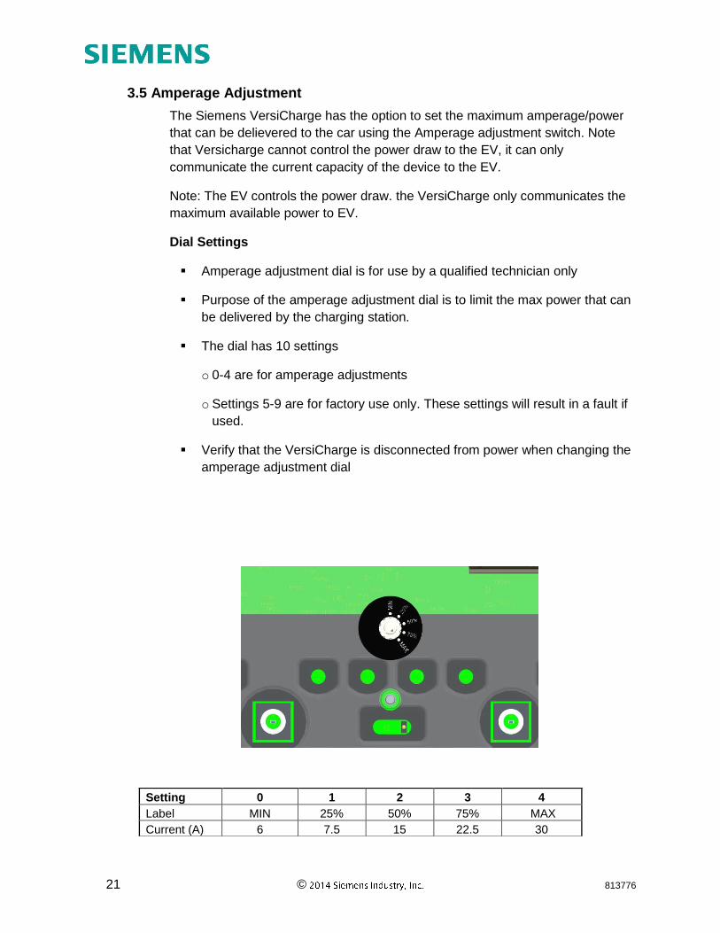
3.5 Amperage Adjustment
The Siemens VersiCharge has the option to set the maximum amperage/power
that can be delievered to the car using the Amperage adjustment switch. Note
that Versicharge cannot control the power draw to the EV, it can only
communicate the current capacity of the device to the EV.
Note: The EV controls the power draw. the VersiCharge only communicates the
maximum available power to EV.
Dial Settings
Amperage adjustment dial is for use by a qualified technician only
Purpose of the amperage adjustment dial is to limit the max power that can
be delivered by the charging station.
The dial has 10 settings
o 0-4 are for amperage adjustments
o Settings 5-9 are for factory use only. These settings will result in a fault if
used.
Verify that the VersiCharge is disconnected from power when changing the
amperage adjustment dial
Setting 0 1 2 3 4
Label MIN 25% 50% 75% MAX
Current (A) 6 7.5 15 22.5 30
22 © 813776
Circuit Requirements
Circuit must be sized for the max ampere requirement. Do not de-rate
breakers or conductors based on amperage adjustment
3.6 Remote Control Interface
The Siemens VersiCharge has a Remote Control Interface that allows charging
to be controlled by an external device. This interface could be used to respond
to a demand response event from a utility.
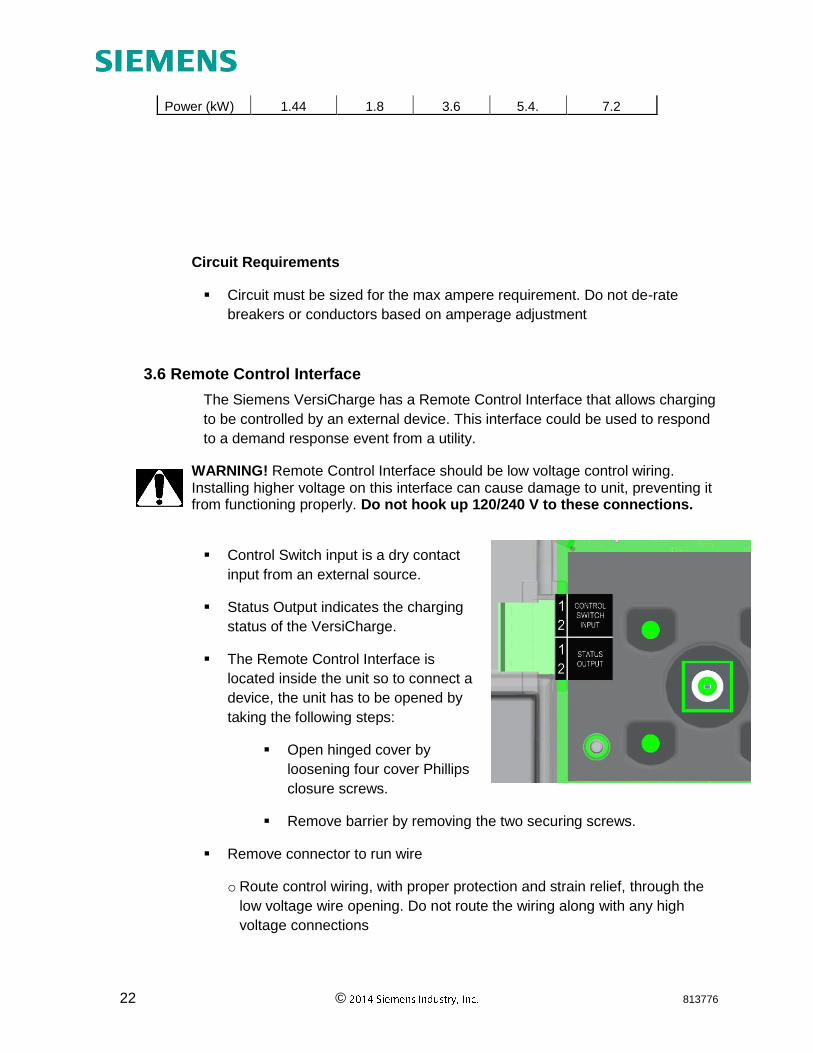
WARNING! Remote Control Interface should be low voltage control wiring. Installing higher voltage on this interface can cause damage to unit, preventing it from functioning properly. Do not hook up 120/240 V to these connections. Control Switch input is a dry contact
input from an external source.
Status Output indicates the charging
status of the VersiCharge.
The Remote Control Interface is
located inside the unit so to connect a
device, the unit has to be opened by
taking the following steps:
Open hinged cover by
loosening four cover Phillips
closure screws.
Remove barrier by removing the two securing screws.
Remove connector to run wire
o Route control wiring, with proper protection and strain relief, through the
low voltage wire opening. Do not route the wiring along with any high
voltage connections
Power (kW) 1.44 1.8 3.6 5.4. 7.2
23 © 813776
o Install external control source according to the instructions provided with
that device
Note: See section 4.7 for more details on this interface
24 © 813776
Section 4: Operation
4.1 Overview
The VersiCharge EV Charging Stations incorporate industry accepted operating standards for EV charging. These include the operation and communication protocols between the VersiCharge and the EV, as well as the required safety features. This section explains in detail the steps of operation.
4.2 Typical Operation
The VersiCharge is primarily a ‘plug-and-play’ device.
Descriptions of various device states can be found in Section 2.6
o Verify that the VersiCharge is in the ‘Power Available’ state by ensuring
that the ‘Power Available’ indicator is illuminated.
o Remove the connector from the connector holster by pressing the button
on the connector handle and pulling the handle away from the
VersiCharge holster
o Plug the connector into the corresponding receiver on the EV. Feel for a
positive connection with a click.
WARNING! Do not force the connector into the receiver on the EV. Forcing the connection can cause damage to the EV and/or the VersiCharge. If the connection between the receiver and the connector shows any resistance, inspect the pins in each, and if damage is found, call a qualified service person.
o If the EV does not require a charge, the VersiCharge will go into the
‘Ready to Charge’ state.
o If the EV does require a charge, the VersiCharge will automatically switch
to the ‘Charging’ state. An audible click is present when the VersiCharge
goes into and out of the ‘Charging’ state.
o Once the charge is complete, or the EV sends a signal to stop charging,
the VersiCharge will automatically return to the ‘Ready to Charge” state.
4.3 Faults
A fault is indicated by a solid red halo, a blinking red halo, and/or the fault LED being illuminated. In any of these conditions, please press the 'Pause' button twice to reset the device. If the condition persists, please turn the circuit breaker feeding the device off, then turn it back on. If the condition still persists, please contact customer support at 1-800-241-4453.
25 © 813776
The VersiCharge will automatically disconnect power in the event of a fault.
If a fault occurs during charging, the VersiCharge will disconnect power
from the EV, with an audible click, and change to the ‘Fault’ state. The
VersiCharge will automatically self-recover when all faults clear, with the
exception of grounding faults.
For grounding faults, after 15 minutes, the VersiCharge will attempt to
continue charging, and if no faults are present, will return to the ‘Charging’
state. During this 15 minute delay, the ‘Fault’ indicator on the unit will blink,
the ‘2 Hour Delay’ indicator is illuminated, and the Halo on the unit will blink
red simultaneously.
If a fault is still present immediately after the VersiCharge re-enters the
‘Charging’ state, the VersiCharge will return to the ‘Fault’ state, and remain
in that state until it is manually reset. During this time the ‘Fault’ indicator
will be illuminated in red, the ‘4 Hour Delay’ indicator will be illuminated, and
the Halo on the unit will be illuminated in a constant red color.
o To reset the device, press the ‘Pause’ button, which will take the device to
the ‘Pause’ state.
o Pressing the ‘Pause’ button again will move the VersiCharge to the
‘Ready to Charge’ state, and if a charge is required, the VersiCharge will
automatically begin charging and move to the ‘Charging’ state.
NOTE: To reset the device you can turn the circuit breaker feeding the device off, then turn it back on.
NOTE: Some cars may delay the command to start charging again when coming out of the ‘Pause” state. Please refer to user manual of the EV if this is happening on your unit.
o If the device continues to experience immediate faults, contact a qualified
person for assistance.
Delay timer LEDs in combination with fault LEDs give more information on fault
type. Please call customer support for more details.
4.4 Cord Management
The VersiCharge has a built in cord management system.
When not in use, the connector cord should be looped over the top of the
VersiCharge unit to prevent accidental damage
The connector should be plugged into the connector holster on the front of
the VersiCharge to prevent accidental damage
26 © 813776
While in use, the cord can be unwrapped, loop by loop, to allow sufficient
length of cord to be unwound to reach the EV receiver
WARNING! Failure to properly protect the connector and the cord could result in damaged components, which could prevent the VersiCharge from functioning properly or create a hazardous situation.
4.5 Delay Timer
The VersiCharge has a built in delay timer to allow users to select the time that they would like for their EV to charge. The delay timer will prevent the VersiCharge from entering the ‘Charging’ state for the selected length of time (2/4/6/8 hours).
From either the ‘Charging’ state or the ‘Ready to Charge’ state, press the
‘Delay Timer’ button
o Pressing the button once, will delay charging to 2 hours
o Pressing the button twice, will delay charging to 4 hours
o Pressing the button three times, will delay charging to 6 hours
o Pressing the button four times, will delay charging to 8 hours
o Pressing the button a fifth time will deactivate the timer and return the
VersiCharge to the ‘ready to Charge’ state, and if the EV requires a
charge, to the ‘Charging’ state
Every two hours, the next ‘hour Delay’ indicator will turn off, so you can tell
how much delay time is remaining by looking at the remaining illuminated
‘Hour Delay’ indicators
o For example: If only the ‘2 Hour Delay’ indicator is illuminated, the delay
has less than 2 hours remaining
o When the delay timer runs out, the VersiCharge unit will automatically
return to ‘ready to Charge’ state, and if the EV requires a charge, to the
‘Charging’ state
4.6 Halo Operation
Halo States
Halo indicator on VersiCharge indicates the status of charging session.
27 © 813776
State Name Description Halo Status
Indicator
Power Available 240V or 208V Power Present Off
Ready to Charge EV detected, waiting for charging
command from EV
Green - Solid
Charging Charging EV Green - Fading in
and out
Pause Operation paused Off
Delay Timer Operation awaiting delay timer Off
Remote System is controlled via remote control
interface
Off
Halo Deactvation
The Halo indicator on the versiCharge can be deactivated to marginally lower power consumption of your device during normal operation. This will prevent the Halo from illuminating in all states, except the ‘Fault’ state.
To de/re-activate the Halo:
o Remove the connector from the EV and place in the connector holster
o Verify that the VersiCharge is in the ‘Power Available’ state by ensuring
that only the ‘Power Available’ indicator is illuminated
o Press and hold both the ‘Pause’ and the ‘Delay Timer’ buttons for 5
seconds. The Halo will blink green three times, and then fade out to off
4.7 Remote Control Interface
The Siemens VersiCharge has a Remote Control Interface that allows charging
to be controlled by an external device. Examples include demand response
switches, building automation systems, digital sensors, etc.
To wire a digital input into the dry contact in the connection area located
inside of the VersiCharge, please refer to the installation section 3.6 of this
manual.
28 © 813776
When the external contact is closed, the alternate input will control the
VersiCharge, preventing it from entering the ‘Charging’ state
The status output is a switch that indicates charging status. When the
contacts are closed, the unit is in charging state
29 © 813776
Section 5: Troubleshooting
5.1 General Settings
Some of the errors that occur are not caused by the VersiCharge, but by the EV compatibility or by settings which are turned on in the EV itself.
If the unit is going into fault, please check the settings in the EV to ensure
that these are not causing the VersiCharge to stop charging. Many EVs
have a setting for time of charge for example in which the user defines a
preference of charging only in certain hours of the day/night. Settings such
as these will override all commands within the VersiCharge for safety
reasons and will thus stop charging your EV. Adjusting the settings in the
car would be the suggested action to take in order to be compatible with the
VersiCharge.
Nuisance fault: As a leader in electrical technology, Siemens has made the
decision to install 5 mA grounding protection in all VersiCharge devices.
This is the same level of protection that is required in kitchens and
bathrooms of residential dwellings. Some other manufacturers (EVSE and
Auto manufacturers) have selected 20 mA protection levels. Because
Siemens units measure to a more sensitive level, occasional charging
interruption may occur under certain circumstances. See section 4.3 for
reset instructions.
5.2 Specific Errors and Actions
The VersiCharge has been designed to self indicate which type of fault has occured.
A fault is indicated by a solid red halo, a blinking red halo, and/or the fault LED being illuminated. In any of these conditions, please press the 'Pause' button twice to reset the device. If the condition persists, please turn the circuit breaker feeding the device off, then turn it back on. If the condition still persists, please contact customer support at 1-800-241-4453.
WARNING! Before taking any of the actions which suggest opening the unit for adjustment, turn off the power supplying the VersiCharge.
30 © 813776
Section 6: Warranty
Limited Warranty Siemens Industry Inc. ("Siemens") has developed a highly reliable EV Supply Equipment (EVSE), branded as VersiCharge (“VersiCharge EVSE”), that is designed to withstand normal operating conditions when used in compliance with the Siemens Installation and Operations Manual supplied with system as originally shipped by Siemens. The Siemens limited warranty (“Limited Warranty”) covers defects in workmanship and materials of the VersiCharge EVSE (“Defective Product”) for a period of three (3) years (the "Warranty Period") from the date of original purchase of such VersiCharge EVSE. The Limited Warranty does not apply to, and Siemens will not be responsible for, any defect in or damage to any Siemens VersiCharge EVSE: (1) that has been misused, neglected, tampered with, altered, or otherwise damaged, either internally or externally; (2) that has been improperly installed, operated, handled or used, including use under conditions for which the product was not designed, use in an unsuitable environment, or use in a manner contrary to the Siemens Installation and Operations Manual or applicable laws or regulations; (3) that has been subjected to fire, water, generalized corrosion, biological infestations, acts of God, or input voltage that creates operating conditions beyond the maximum or minimum limits listed in the Siemens VersiCharge EVSE specifications, including high input voltage from generators or lightning strikes; (4) that has been subjected to incidental or consequential damage caused by defects of other components of the electrical system; or (5) if the original identification markings (including trademark or serial number) of such VersiCharge EVSE have been defaced, altered, or removed. The Limited Warranty does not cover costs related to the removal, installation or troubleshooting of the customer's electrical systems. The Limited Warranty does not extend beyond the original cost of the Siemens VersiCharge EVSE. During the Warranty Period, Siemens will, at its option, repair or replace the Defective Product free of charge, provided that Siemens through inspection establishes the existence of a defect that is covered by the Limited Warranty. Siemens will, at its option, use new and/or reconditioned parts in repairing or replacing the Defective Product. Siemens reserves the right to use parts or products of original or improved design in the repair or replacement of Defective Product. If Siemens repairs or replaces a Defective Product, the Limited Warranty continues on the repaired or replacement product for the remainder of the original Warranty Period or ninety (90) days from the date of Siemens’s return shipment of the repaired or replacement product, whichever is later. The Limited Warranty covers both parts and labor necessary to repair the Defective Product, but does not include labor costs related to un-installing the Defective Product or re-installing the repaired or replacement product. The Limited Warranty also covers the costs of shipping repaired or replacement
31 © 813776
product from Siemens, via a non-expedited freight carrier selected by Siemens, to locations within the United States (including Alaska and Hawaii) and Canada, but not to other locations outside the United States or Canada. The Limited Warranty does not cover shipping damage or damage resulting from mishandling by the freight carrier. Any such damage is the responsibility of the freight carrier. To obtain repair or replacement service under this Limited Warranty, the customer must comply with the following policy and procedure:
All Defective Product must be returned with a Return Merchandise Authorization Number (RMA) which customer must request from Siemens.
RMA request must include the following information: o Proof-of-purchase of the Defective Product in the form of (1) the dated
purchase receipt from the original purchase of the product at point of sale to the end user, or (2) the dated dealer invoice or purchase receipt showing original equipment manufacturer (OEM) status, or (3) the dated invoice or purchase receipt showing the product exchanged under warranty.
o Model number of the Defective Product o Serial number of the Defective Product o Detailed description of the defect o Shipping address for return of the repaired or replacement product
All Defective Product authorized for return must be returned in the original shipping container or other packaging that is equally protective of the product
The returned Defective Product must not have been disassembled or modified without the prior written authorization of Siemens
THE LIMITED WARRANTY IS THE SOLE AND EXCLUSIVE WARRANTY GIVEN BY SIEMENS AND, WHERE PERMITTED BY LAW, IS MADE EXPRESSLY IN LIEU OF ALL OTHER WARRANTIES, EXPRESS OR IMPLIED, STATUTORY OR OTHERWISE, INCLUDING, WITHOUT LIMITATION, WARRANTIES OF TITLE, QUALITY, MERCHANTABILITY, FITNESS FOR A PARTICULAR PURPOSE OR NON-INFRINGEMENT OR WARRANTIES AS TO THE ACCURACY, SUFFICIENCY OR SUITABILITY OF ANY TECHNICAL OR OTHER INFORMATION PROVIDED IN MANUALS OR OTHER DOCUMENTATION. IN NO EVENT WILL SIEMENS BE LIABLE FOR ANY SPECIAL, DIRECT, INDIRECT, INCIDENTAL OR CONSEQUENTIAL DAMAGES, LOSSES, COSTS OR EXPENSES HOWEVER ARISING, WHETHER IN CONTRACT OR TORT, INCLUDING WITHOUT LIMITATION ANY ECONOMIC LOSSES OF ANY KIND, ANY LOSS OR DAMAGE TO PROPERTY, OR ANY PERSONAL INJURY. To the extent any implied warranties are required under applicable law to apply to the Siemens VersiCharge EVSE, such implied warranties shall, to the extent permitted by applicable law, be limited in duration to the Warranty Period. In states and provinces which do not allow limitations or exclusions on implied warranties or on the duration of an implied warranty or on the limitation or exclusion of incidental or consequential damages, the above limitation(s) or
32 © 813776
exclusion(s) may not apply. This Limited Warranty gives the customer specific legal rights. The customer may have other rights that vary from state to state or province to province.
33 © 813776
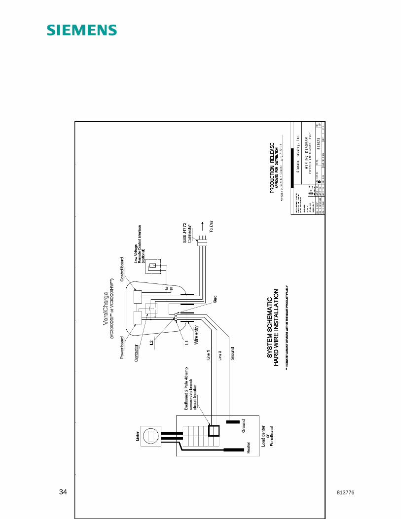
Section 7: Wiring Diagrams
34 © 813776


