Safety Information ............................................................................................. 4
Installation Instructions...................................................................................... 5 Startup and Checkout…………………………................................................ 8
Theory of Operation........................................................................................... 9 LED indicators................................................................................................... 10 Alarm Contact Closures..................................................................................... 11
2
DESCRIPTION
The SEI 1200/48-2U-P-ACC DC-UPS is a compact unit designed to power a wide range of customer equipment requiring battery-backed 48 VDC power. The unit comes equipped with 1200 Watts of rectifier power. The power distribution is provided on the rear of the unit a pair of fused 10/32 studs suitable for a two-hole compression lug. Commercial power is applied to the left side of the rear. . The Alarm Contact Closures (ACC) are accessed via an RJ-45 jack on the left side of the rear of the unit. The SEI DC-UPS can be mounted on a 19-inch rack and occupies 2U (3.5 inches) of rack space.
The SEI 1200/48-2U-P-ACC comes equipped with two field replaceable, non-spillable sealed lead acid battery packs. Both battery packs must be installed to provide back-up power. Circuitry within the DC UPS monitors and periodically tests the condition of the batteries and displays the results via front panel LEDs as well as via the Alarm Contact Closures (ACC). Loss of AC power is also communicated via the ACC. The DC UPS utilizes a Low Voltage Disconnect, (LVD), circuit that prevents damage to the Battery Packs during an extended AC outage.
3
TECHNICAL SPECIFICATIONS
SEI 1200/48-2U-P-ACC AC Input Power Voltage 85-264 Vac Frequency 47-63 Hz Current (120 Vac input, 1200 W output) 12 Amps Typical 15 Amps Max (240 Vac input, 1200 W output) 6.0 Amps Typical 7.5 Amps Max DC Output Power Voltage 42.0 – 54.8 Vdc Power 1200W max Current 28.6 Amps max Fuse Rating 30 amps Internal Battery Capacity Range 9 Ahr Fuse Rating 50 amps
ENVIRONMENTAL SPECIFICATIONS Temperature Operating 0 C to +50 C Storage -20 C to +50 C Humidity 0-95% non-condensing
Thermal Load SEI-1200 550 BTU/hr max
4
SAFETY INFORMATION Always insure that the person assigned to the job can perform the job safely.
Always lift all equipment properly. Always disconnect commercial power and remove the battery fuse before working
on the unit. Always replace the batteries with batteries of the same type and style. DO NOT work on this equipment during an electrical storm. DO NOT work in locations where there is condensing moisture or standing water. Service to the DC UPS should be performed by a qualified technician.
5
INSTALLATION INSTRUCTIONS
GENERAL The installation section of this manual will provide all the necessary
information for room requirements, proper inspection, and installation.
Inspection The equipment has been fully tested and inspected prior to shipment.
Although the unit has been packed in accordance with good commercial practices, it does not preclude damage in transit.
The following actions should be taken on receipt of the equipment:
Visually inspect the shipping container for damage. If damaged, request that the carrier inspect the shipment.
Unpack the inner container from the shipping container and remove
the unit from the packaging. Inspect the unit for visible damage. If a claim for damages is to be made, it should be filed promptly with the
transportation company. In addition, notify SEI within two days of delivery. SEI will advise the customer of any further procedures that may be required, including an RMA number in the event that the unit has to be returned to the factory for repair.
Make sure the following items are included inside the package:
SEI 1200/48-2U-P-ACC DC-UPS One Installation and Operations Manual. One AC Power Cord.
6
Room Requirements Electrical Requirements
Each unit requires a separate NEMA 5-15R receptacle protected by a 15 Amp circuit
breaker. A standard 7 foot 6 inch power cord with a molded NEMA 5-15 plug is supplied
with each unit. Mounting Instructions
1. Unit Weight - The SEI 1200/48-2U-P-ACC weighs 45 lbs with the battery packs installed and 20 lbs without the battery packs installed. It is recommended to mount the unit before installing the battery pack.
2. Rack Mounting - The SEI DC-UPS is designed to mount to a 19” rack using two racks screws per side. The mounting slots on each rack adapter are spaced in conformance with EIA standard RS-310-B.
3. Ventilation - It is important that the DC-UPS’s ventilation ports not be blocked. Therefore, leave adequate space on front and both sides of the unit to ensure unrestricted airflow to the unit. It is recommended that a minimum of 3 inches of space be allowed on both sides of the unit. The unit should be installed in a clean dry area where the ambient temperature does not exceed 50°C.
4. Battery Pack Installation a. Open Front Panel – Loosen the two thumbscrews on the front of the DC-
UPS. Fold down the front panel. b. Install Battery Packs – Slide each of the two battery packs into the DC-UPS
Chassis. The battery packs should be oriented so that the attached connectors point to the middle of the unit.
c. Attach the red and black connector of each battery pack to the one of the red and black connectors in the center conduit of the DC-UPS. Either battery pack can be connected to either DC-UPS connector
d. Gently push the connected red and black connectors into the center conduit. e. Close the Front Panel – Fold up the front panel and secure the two
thumbscrews. 5. Attach Customer Equipment - Attach the equipment to be powered to the 10/32
studs on the rear of the DC-UPS. Install the provide ATO style fuse.
7
Figure 1 10/32 terminal Output Port
6. Attach to the ACC connector – Using a standard Cat 3 or better patch cord, connect
to the DC-UPS Alarm Contact Closures via the RJ45 receptacle on the rear of the DC-UPS.
7. Attach the AC-Power Cord – Attach the provide AC Power Cord to the IEC receptacle on the rear of the DC-UPS.
. Figure 2 ACCand AC connections
+48Vdc Terminals
48rtn Terminals
Output Port Fuse
AC Power Cord Connection
ACC Connection
8
START UP AND CHECKOUT
Power On Checkout.
1. Once the unit is properly mounted, you may begin the checkout procedure. First, insure that all the equipment to be powered by the unit is installed.
2. Plug in the DC-UPS power cord into the commercial AC outlet made available for this unit.
3. When power is first applied, the front panel LEDs will go through a start-up sequence of red, green and flashing yellow. The DC-UPS fans will also start-up.
4. After the start-up sequence, the Port 1 LED will turn on green. Verify that the connected customer equipment is receiving power. Port 2 will turn on two seconds after Port 1
5. The Battery Charge Status LED will flash green. This indicates that the Battery Pack is charging.
6. Disconnect the AC power cord. Verify that the Battery Charge Status LED and the System Status LED are flashing red. If there is no load on the DC-UPS this may take several seconds. Verify that the connected equipment is still receiving power.
7. Reconnect the AC power cord. The Battery Charge Status LED will flash green. This indicates that the batteries are charging.
8. If you have a specific question not addressed in this manual, please call 301-694-9601, for technical support.
SYSTEM SHUTDOWN
1. The SEI 1200/48-2U-P-ACC DC-UPS is an uninterruptible power system. Therefore, removing the AC power feed to the unit will not shutdown the DC power distributed to the loads until the battery pack is full discharged.
2. Disconnect the AC power Cord. 3. Verify that the Battery Status LED and the System Status LED are flashing red. 4. Press and hold the Manual Battery Test Switch for 5 seconds. The Battery Test
Status LED will quick flash red. 5. All front panel LEDS will turn off, the unit fans will stop and the connected
equipment will power down.
9
THEORY OF OPERATION
Theory of Operation The following will provide you with an outline of operations and a list of modules found in the DC-UPS. Modules
Rectifiers System Controller/LVD Battery Module Distribution and Connectors Alarm Contact Closures (ACC)
Functional Block Diagram DC-UPS Figure 1
Rectifier The 600W rectifiers convert AC input power to regulated DC output power. The input of the rectifier is fused for protection... System Controller/LVD The System Controller has the following functions:
Distribution of the DC power Battery charge voltage and current control and monitoring Load monitoring and overload control Battery Low Voltage Disconnect Function (LVD) Battery charge and test status indicators Automatic and manual battery test
RECTIFIER(S)
SYSTEM CONTROLLER
DISTRIBUTION MODULE(S)
BATTERY PACK
ACC
10
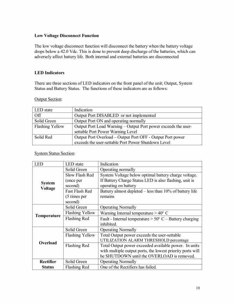
Low Voltage Disconnect Function The low voltage disconnect function will disconnect the battery when the battery voltage drops below a 42.0 Vdc. This is done to prevent deep discharge of the batteries, which can adversely affect battery life. Both internal and external batteries are disconnected LED Indicators There are three sections of LED indicators on the front panel of the unit; Output, System Status and Battery Status. The functions of these indicators are as follows: Output Section: LED state Indication Off Output Port DISABLED or not implemented Solid Green Output Port ON and operating normally Flashing Yellow Output Port Load Warning – Output Port power exceeds the user-
settable Port Power Warning Level Solid Red Output Port Overload – Output Port OFF - Output Port power
exceeds the user-settable Port Power Shutdown Level System Status Section: LED LED state Indication
Solid Green Operating normally Slow Flash Red (once per second)
System Voltage below optimal battery charge voltage. If Battery Charge Status LED is also flashing, unit is operating on battery System
Voltage Fast Flash Red (5 times per second)
Battery almost depleted – less than 10% of battery life remains
Solid Green Operating Normally Flashing Yellow Warning Internal temperature > 40 C Temperature Flashing Red Fault - Internal temperature > 50 C – Battery charging
inhibited. Solid Green Operating Normally Flashing Yellow Total Output power exceeds the user-settable
UTILIZATION ALARM THRESHOLD percentage Overload Flashing Red Total Output power exceeded available power. In units with multiple output ports, the lowest priority ports will be SHUTDOWN until the OVERLOAD is removed.
Solid Green Operating Normally Rectifier Status Flashing Red One of the Rectifiers has failed.
11
Battery Status Section: LED LED state Indication
Solid Green Battery fully charged Flashing Green Battery charging
Battery Charge Status Flashing Red Unit operating on battery power
Off Battery under Test Green Battery Test Pass – Battery OK Slow Flash Red (5 times per second)
Battery Test Fail – Replace Battery Packs. Battery Test
Status Fast Flash Red (5 times per second)
Battery Test not Allowed
Manual Battery Test
Switch
Push to Test Battery Test not allowed when battery is charging, when there is a system fault condition, or within one minute of a previous battery test
Alarm Contact Closures Option The DC-UPS Alarm Contact Closures Option provides relay contacts to remotely monitor the status of the unit. These alarms will indicate either an AC Fail or a Battery Test Fail condition. Both normally open and normally closed contacts are provided to suite the user’s external monitoring circuitry. The alarm contacts have a 2 Amp rating. The NO and NC contacts will change state when an alarm condition occurs. The alarm contacts are accessible via an RJ45 connector on the rear of the DC-UPS. The Alarm Contact connector pinouts in the table below:
Pin # Function Comment 1 Battery Test Fail NC Battery OK 2 Battery Test Fail Common 3 Battery Test NO Battery Test failed 4 No connection 5 No connection 6 AC Fail NC AC Failure has occurred 7 AC Fail Common 8 AC FAIL NO Operating Normally