7 747 000 512 – 07/2006 US For installers Please read carefully prior to installation and maintenance. Installation and Service Instructions Gas boiler Logano GC124 II/SP CAUTION! Before placing this boiler in operation observe the safety instructions of this installation and maintenance manual. WARNING! Installation, adjustment, modification, operation or maintenance of the heating system carried out by unqualified personnel may result in property damage, personal injury, and loss of life. The directions of this installation and maintenance manual must be followed precisely. Contact a qualified service company, service provider or the gas company if support or additional information is required. CAUTION! The operating manual is a component of the technical documentation handed over to the operator of the heating system. Discuss the instructions in this manual with the owner or operator of the heating system and ensure that they are familiar with all information required for operation of the heating system. In the Commonwealth of Massachusetts this boiler must be installed by a licensed plumber or gas fitter. Keep this installation and maintenance manual available for future reference.
Transcript
7 747 000 512 – 07/2006 US For installers
Please read carefully prior to installation and maintenance.
Installation and Service Instructions
Gas boilerLogano GC124 II/SP
CAUTION!Before placing this boiler in operation observe the safety instructions of this installation and maintenance manual.
WARNING!Installation, adjustment, modification, operation or maintenance of the heating system carried out by unqualified personnel may result in property damage, personal injury, and loss of life.The directions of this installation and maintenance manual must be followed precisely.Contact a qualified service company, service provider or the gas company if support or additional information is required.
CAUTION!
The operating manual is a component of the technical documentation handed over to the operator of the heating system. Discuss the instructions in this manual with the owner or operator of the heating system and ensure that they are familiar with all information required for operation of the heating system.In the Commonwealth of Massachusetts this boiler must be installed by a licensed plumber or gas fitter.
Keep this installation and maintenance manual available for future reference.
We reserve the right to make any changes due to technical modifications.
Installation and Service Instructions Gas Boiler Logano GC124 II/SP • Issue 07/2006
Safety considerations1
1 Safety considerations
Observe these instructions for your safety.
The burner and control must be correctly installed and adjusted to ensure safe and economical operation of the gas boiler.
Read this installation and maintenance manual carefully and note the details on the boiler nameplate before placing the boiler in operation.
1.1 Correct use
The Logano GC124 II/SP atmospheric gas boiler is designed to heat water for a hot water heating system for heating single or multiple occupancy buildings.
1.2 Observe the following symbols
Two levels of danger are identified and signified by the following terms:
Additional symbols for identification of dangers and user instructions:
1.3 Observe the following guidelines
1.3.1 National regulations
The heating system must comply with the relevant regulations issued by national authorities, or the regulations issued by the National Fuel Gas Code, ANSI Z 223.1.
If specified by the local regulatory authorities the heating system must comply with the regulations of the "Standard for Controls and Safety Devices for Automatically Fired Boilers," ANSI/ASME CSD-1.
Carbon monoxide detectors must be installed as specified by the local regulations. The boiler must be serviced annually ( Chapter 16, page 43).
Boiler Operating Conditions
The hot water piping system must comply with the current legislation and local regulations. If an existing boiler is replaced, the complete hot water piping system must be inspected to ensure that it is in perfect condition to ensure safe operation.
WARNING!
RISK TO LIFE
Identifies possible dangers originating from the product, which might lead to serious injury or death if proper care is not taken.
CAUTION!
RISK OF INJURYSYSTEM DAMAGE
Identifies potentially dangerous situations, which might lead to medium or minor injuries or to material losses if proper caution is not followed.
WARNING!
RISK TO LIFE
from electrical shock.
USER NOTE
Guidelines for the optimum use and setting of the control(s) plus other useful information.
Maximum boiler temperature: 220 °FMaximum operating pressure: 58 psi
WARNING!
RISK TO LIFE
due to neglecting your own safety in case of emergency, such as with a fire.
Never put yourself at risk. Your own safety must always take priority.
WARNING!
RISK TO LIFE
from explosion of flammable gases.
If you smell gas there is a danger of explosion.
Never work on gas lines unless you are licensed for this type of work.
Make sure that a qualified company installs the boiler, connects gas and ventplaces the boiler in operation, connects the electrical power, and maintains and repairs the boiler.
No open flame! No smoking! Do not use lighters
Prevent spark formation. Do not operate electrical switches, including telephones, plugs or door bells.
Close main gas valve.
Open doors and windows.
Warn other occupants of the building, but do not use door bells.
Call gas company from outside the building.
If gas can be heard escaping, leave the building immediately, prevent other people from entering, notify police and fire departments from outside the building.
4 Installation and maintenance instructions Gas Boiler Logano GC124 II/SP • Issue 07/2006
We reserve the right to make any changes due to technical modifications.
Safety considerations 1
1.3.2 Installation notes
1.3.3 Information on the boiler room
CAUTION!
SYSTEM DAMAGE
due to incorrect installation.
Observe all current standards and guidelines applicable to the installation and operation of the boiler heating system as applicable in your state or local jurisdiction.
WARNING!
RISK TO LIFE
from electrical shock.
Disconnect the power supply to the boiler heating system before conducting any work on it, e.g. turn off the heating system emergency switch outside the boiler room.
It is not sufficient just to turn off the control.
CAUTION!
SYSTEM DAMAGE
due to unsatisfactory cleaning and boiler maintenance.
Clean and service the boiler system once a year. Check that the complete heating system operates correctly.
Immediately correct all faults to prevent system damage.
USER NOTE
Only use original Buderus spare parts. Losses caused by the use of parts not supplied by Buderus are excluded from the Buderus warranty.
WARNING!
RISK TO LIFE
from explosion of flammable gases.
Never work on gas lines unless you are licensed for this type of work.
WARNING!
RISK TO LIFE
from electrical shock.
Do not carry out electrical work unless you are qualified for this type of work.
Before disconnect electrical power completely and pad lock to prevent accidental reconnection.
Observe the local installation regulations.
WARNING!
RISK TO LIFE
by poisoning.
Insufficient ventilation or combustion air availability may cause dangerous flue gas leaks or formation.
Make sure that inlets and outlets are not reduced in size or closed.
If faults are not corrected immediately, the boiler must not be operated until all faults have been corrected.
Inform the system operator and/or owner of the fault and the danger in writing.
WARNING!
RISK TO LIFE
by poisoning.
When working on the flue gas venting equipment or vent damper leakage of flue gases may endanger the lives of people.
Carefully observe proper operation of the vent damper. Do not start up the boiler unless the vent damper is operating properly.
Use only original parts when replacing parts.
When replacing the vent damper, install the new one in the specified position.
WARNING!
RISK TO LIFE
by poisoning by spillage of flue gases.
If the blocked vent switch, attached to the open draft hood in the rear of the boiler trips frequently, there may be a problem with the chimney or the flue gas venting system.
If the blocked vent switch trips frequently the fault must be corrected and proper operation of the blocked vent switch test must be conducted.
WARNING!
RISK TO LIFE
by poisoning by leakage of flue gases.
Make sure that the boiler is not equipped with a thermally controlled flue gas vent damper after the open draft hood.
5
We reserve the right to make any changes due to technical modifications.
Installation and maintenance instructions Gas Boiler Logano GC124 II/SP • Issue 07/2006
Safety considerations1
1.4 Tools, materials and accessories
You need standard tools for the installation and maintenance of the boiler as used in boiler heating system installation and oil, gas and water installations.
The following additional items will also be useful:
– Boiler cart with strap.
– Cleaning brushes and/or chemical cleaning agents for wet cleaning of the cast iron heat exchanger.
1.5 Disposal
Dispose of the packaging material in an environmentally prudent fashion.
Dispose of any components of the heating system that require replacement in an environmentally prudent fashion.
WARNING!
FIRE DANGER
due to flammable materials or liquids.
Make sure that there are no flammable materials or liquids in the immediate vicinity of the boiler.
Maintain a minimum distance of 15 inches from the boiler.
6 Installation and maintenance instructions Gas Boiler Logano GC124 II/SP • Issue 07/2006
We reserve the right to make any changes due to technical modifications.
Product Description 2
7
We reserve the right to make any changes due to technical modifications.
Installation and maintenance instructions Gas Boiler Logano GC124 II/SP • Issue 07/2006
2 Product Description
The boiler is a low temperature gas boiler.
The boiler consists of the following main components:
– Ignition module (GC124 II only) and adjustable aquastat
– Boiler jacket and front door
– Boiler block with insulation
– Burner
The ignition module and adjustable aquastat monitor and control all electrical and operational components of the boiler.
The boiler jacket prevents energy loss and acts as soundproofing.
The boiler block transfers the heat generated by the burner to the heating water. The insulation reduces energy loss.
Fig. 1 Logano GC124 II/SP gas boiler
1 Boiler front door
2 Aquastat (boiler temperature controller)
3 Ignition module (GC124 II only)4 Boiler block with insulation
5 Burner
6 Boiler jacket
�����������������
6
1
5
3
4
2
GC124 II
GC124 SP
6
1
5
4
2
8 Installation and maintenance instructions Gas Boiler Logano GC124 II/SP • Issue 07/2006
We reserve the right to make any changes due to technical modifications
Dimensions and Connections3
3 Dimensions and Connections
Tab. 1 Dimensions/specs for GC124 II and GC124 SP
Fig. 2 Back, side and front view, measurements in inches
* optional connection
2
3/8
RK 1¼"
VK 1¼"
GAS ½"
EL ¾"(GAS ½")*
Connections (measurements see the following tables):VK = Boiler supplyRK = Boiler return EL = Boiler drainGAS = Gas connection
Boiler size
Boilerinput
A B Vent connection II/SP
Min. relief valve capacity
Number of Orifices
Water volume
Dry weight
Btu/hr Inches Inches Inches lb/hr Qty. US Gal. lbs
18/3 74000 13 1/8" 8" 5" 62 2 2.4 228
25/4 103000 16 3/4" 8 2/3" 5" 86 3 2.9 287
32/5 132500 20 3/8" 9 1/2" 6" 110 4 3.4 349.5
Fig. 3 Pressure drop/boiler
USER NOTE
For the size and dimensions of the main gas orifices, refer to Chapter 18, page 79.
Scope of delivery 4
9
We reserve the right to make any changes due to technical modifications.
Installation and maintenance instructions Gas Boiler Logano GC124 II/SP • Issue 07/2006
4 Scope of delivery
Check packaging upon receipt of delivery for dam-age.
This chapter describes how to move the boiler safely into place.
5.1 Moving the boiler with boiler cart
Move the boiler with packaging in tact and on its pallet as much as possible.
Remove packaging straps and cardboard box from pallet.
Remove screws that secure the boiler base to the wood pallet.
Pick up boiler base from one side and slide to the edge of the pallet. Place a steel pipe as roller under the boiler base. Place additional steel pipes under the boiler base and roll the boiler to its final destina-tion.
CAUTION!
SYSTEM DAMAGE
Due to uneven and rough surfaces.
Observe the transport diagrams on the packaging to protect the sensitive com-ponents from damage due to rough sur-faces. Handle the product with care.
USER NOTE
Protect all boiler connections from dirt if the boiler is not installed immediately following removal from packaging.
USER NOTE
Dispose of the packaging material in an environmentally prudent fashion.
Fig. 4 Moving the boiler with rollers
10 Installation and maintenance instructions Gas Boiler Logano GC124 II/SP • Issue 07/2006
We reserve the right to make any changes due to technical modifications.
Moving the boiler 5
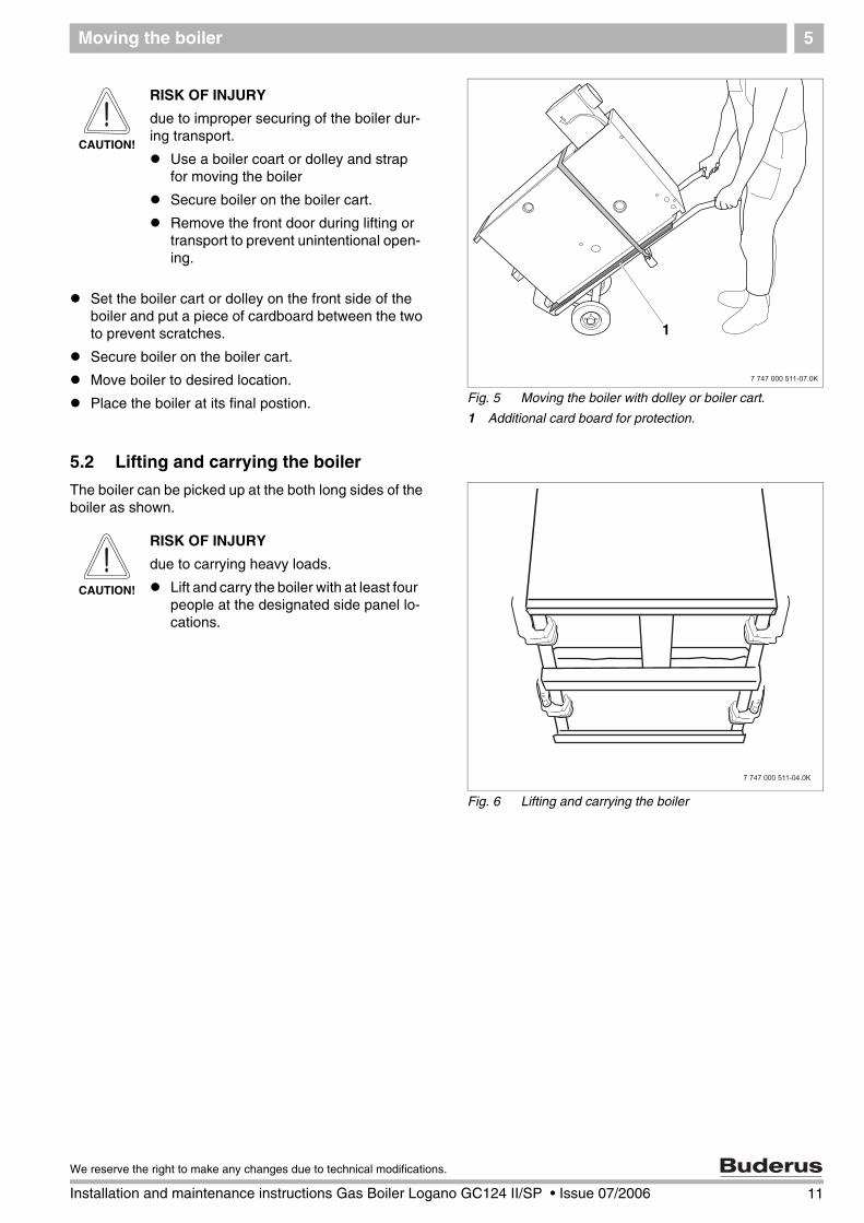
Set the boiler cart or dolley on the front side of the boiler and put a piece of cardboard between the two to prevent scratches.
Secure boiler on the boiler cart.
Move boiler to desired location.
Place the boiler at its final postion.
5.2 Lifting and carrying the boiler
The boiler can be picked up at the both long sides of the boiler as shown.
Fig. 5 Moving the boiler with dolley or boiler cart.
1 Additional card board for protection.
1
CAUTION!
RISK OF INJURY
due to improper securing of the boiler dur-ing transport.
Use a boiler coart or dolley and strap for moving the boiler
Secure boiler on the boiler cart.
Remove the front door during lifting or transport to prevent unintentional open-ing.
Fig. 6 Lifting and carrying the boiler
�����������������
CAUTION!
RISK OF INJURY
due to carrying heavy loads.
Lift and carry the boiler with at least four people at the designated side panel lo-cations.
11
We reserve the right to make any changes due to technical modifications.
Installation and maintenance instructions Gas Boiler Logano GC124 II/SP • Issue 07/2006
12 Installation and maintenance instructions Gas Boiler Logano GC124 II/SP • Issue 07/2006
We reserve the right to make any changes due to technical modifications.
Placing the boiler6
6 Placing the boiler
This chapter explains how to place the boiler and posi-tion it in the boiler room.
The boiler is very heavy when filled with water. Check that the floor can bear the weight before installation.
6.1 Clearances
The GC124 boiler is approved for closet installation. The following minimum distances must then be main-tained:
– front: 2",– sides: 2",– behind open draft hood: 6",– above boiler top panel: 30".
A space of at least 33 inches is recommended in front of the boiler with the door removed to allow sufficient ac-cess space for operation and maintenance. When the door is closed, a minimum clearance of 2 inches is re-quired at the front and sides, 2 inches clearance is also required for the flue pipe and 30 inches clearance to the ceiling. The installation location and the base must be smooth and horizontal.The boiler may be installed on a flammable base, but not on carpet.
6.2 Leveling the boiler
Level the boiler in both horizontal directions.
Level the boiler using a level and place small wedges (not supplied) for leveling purposes.
CAUTION!
SYSTEM DAMAGE
due to frost.
Place the boiler in a frost-free room.
Fig. 7 Required clearances in the boiler room
1 Recommended service clearances2 Required minimum clearances
3 Burner tray access door with combustion air opening as required per ANSI Z.223.1
1
2
3
Boiler installation 7
7 Boiler installation
This chapter describes how to install the boiler. This in-cludes the following tasks:
– Connecting the heating system
– Electrical connection
– Gas supply piping connection
7.1 Preparing for installation
Unpack all boxes and containers and check all parts against the packing lists to make sure that everything has been supplied.
USER NOTE
Every boiler is carefully inspected and tested before it leaves the factory. How-ever, if you discover any damage or miss-ing parts, please inform your supplier im-mediately. Before disposing of packing material, make sure that no parts are still in it.
USER NOTE
For better access remove the front door.
13
We reserve the right to make any changes due to technical modifications.
Installation and maintenance instructions Gas Boiler Logano GC124 II/SP • Issue 07/2006
Boiler installation7
7.2 Connecting the heating system
Fig. 8 Low-water cut-off installation
1 Boiler
2 Radiator
3 Heating system with low-water cut-of4 Heating system without low-water cut-off
1
2
2
12
2
2
2
3
4
CAUTION!
BOILER DAMAGE
Due to moisture.
Protect the components of the gas igni-tion system from moisture (dripping, spray, rain) during installation of the boiler, during operation and during maintenance work (such as replacing the pump, replacing the control, etc.).
CAUTION!
SYSTEM DAMAGE
Due to overheating as a result of a low wa-ter condition.
Note that a boiler installed above the level of the heating system must be equipped with a low-water cut-off. The low-water cut-off must be installed dur-ing installation of the boiler and placed above the water level in the boiler with-out any means of shutting the water off between the boiler and low water cut-off ( Fig. 8).
CAUTION!
SYSTEM DAMAGE
Due to high temperature variations in the heating system.
If the boiler is operated in connection with a refrigeration system, make sure that the pipes for the refrigerated liquid are connected in parallel to the boiler system with suitable valves to prevent the refrigerated liquid from entering the boiler.
The piping system of a boiler connect-ed to the heating coils of hydro-air heat-ing systems that may be exposed to the circulation of cooled air must be equipped with a flow-control valve or some other automatic system for pre-venting the boiler water from circulating by gravity during the cooling cycle.
14 Installation and maintenance instructions Gas Boiler Logano GC124 II/SP • Issue 07/2006
We reserve the right to make any changes due to technical modifications.
Boiler installation 7
Installation of B-kit
The relief valve and the pressure/temperature gauge are mounted on the boiler supply manifold which is attached to the VK (supply) connection of the boiler (included in B-kit).
Installing boiler supply VK:
Remove factory installed plastic inserts from boiler supply (VK), boiler return (RK) and boiler drain (EL) connections.
Install the 1¼"NPT nipple into boiler supply, the 1" NPT nipple into boiler return and ¾" male NPT drain valve into boiler drain connection.
Install 90° 1¼" x 1¼"NPT on 1¼" NPT supply nipple and face upward and install 90° 1¼" x 1"NPT elbow on return nipple and face in desired direction.
Install GC124 1¼" x 1¼"NPT supply manifold into supply connection (VK) of the boiler. Do NOT place on return connection of the boiler!
Install first 90° ¾" street elbow in upper ¾" NPT tap-ping of GC124 1-1/4" supply manifold and install pressure relief valve into this ¾" tapping. Make sure to orient the discharge of the relief valve horizontally. Install the temperature/pressure gauge in the lower 3/4" tapping of the supply manifold.
Fig. 9 Installation of B-kit
1 Pressure relief valve ¾"2 90° 3/4" street elbow
3 GC124 1-1/4" supply manifold
4 Pressure & temperature gauge5 90° 1-1/4" NPT elbow
6 1-1/4" NPT nipple
7 Boiler drain ¾" NPT (backside of boiler)8 90° 1-1/4" x 1" NPT elbow
9 1" NPT nipple
1
2
4
5
8
VK
RK
6
9
EL7
3
USER NOTE
Install the relief valve after the leak test. ( Chapter 7.5, page 20).
The relief valve must be installed in a ver-tical position.
The relief valve must also be installed in accordance with the requirements of the ANSI/ASME Boiler and Pressure Vessel Code, Section IV.
USER NOTE
We recommend installing a y-strainer (ac-cessory) in the boiler return connection to reduce build-up of debris on the water side inside the boiler.
USER NOTE
Ensure compliance with all state and local regulations pertaining to the installation of boiler systems.
15
We reserve the right to make any changes due to technical modifications.
Installation and maintenance instructions Gas Boiler Logano GC124 II/SP • Issue 07/2006
Boiler installation7
7.3 Electrical connections
The electrical connections of the boiler must be made as specified by the local codes and the current regulations of the National Electrical Code, ANSI/NFPA–70.
The boiler must be grounded as specified by the regula-tions of the relevant local authorities; otherwise follow the regulations of the National Electrical Code, ANSI/NFPA–70.
The boiler is fully functional with the factory installed aquastat and the field installed vent damper and heating system circulation pump.
Power supply connection.
Install incoming power to the boiler per local and state codes.
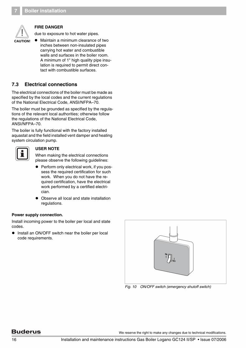
Install an ON/OFF switch near the boiler per local code requirements.
CAUTION!
FIRE DANGER
due to exposure to hot water pipes.
Maintain a minimum clearance of two inches between non-insulated pipes carrying hot water and combustible walls and surfaces in the boiler room. A minimum of 1" high quality pipe insu-lation is required to permit direct con-tact with combustible surfaces.
USER NOTE
When making the electrical connections please observe the following guidelines:
Perform only electrical work, if you pos-sess the required certification for such work. When you do not have the re-quired certification, have the electrical work performed by a certified electri-cian.
Observe all local and state installation regulations.
Fig. 10 ON/OFF switch (emergency shutoff switch)
16 Installation and maintenance instructions Gas Boiler Logano GC124 II/SP • Issue 07/2006
We reserve the right to make any changes due to technical modifications.
Boiler installation 7
Description of field installed wiring connections using factory supplied junction box.
Remove two knock-outs from the left side of boiler panel to route electrical feed and pump power into junction box.
Route electrical power from the outside into junction box.
Install a metal strain relief for the incoming power line on outside of left boiler jacket panel. ( Fig. 12).
Just use supplied wiring nuts and double proper wir-ing before powering up the boiler.
Check that the heating system functions correctly af-ter any maintenance work.
Fig. 11 Electrical junction box
1 Electrical junction box (Inside of jacket cabinet)
2 Incoming line voltage wiring3 Furnished wiring nuts.
2
1
3
USER NOTE
When making the electrical connections use only wires that are approved for elec-trical use.
USER NOTE
Refer to the wiring diagrams on pages page 80 bis page 82 for electrical
details.
Fig. 12 Strain relief for shielded electrical wiring
WARNING!
RISK TO LIFE
from electrical shock.
When conducting maintenance work label all cables before disconnecting them.
If cables are connected incorrectly the system may not operate correctly with possibly dangerous consequences.
WARNING!
FIRE DANGER
Hot boiler components may damage elec-trical wiring.
Make sure that all cables are routed in the ducts or on the boiler insulation.
17
We reserve the right to make any changes due to technical modifications.
Installation and maintenance instructions Gas Boiler Logano GC124 II/SP • Issue 07/2006
Boiler installation7
7.4 Fuel gas supply connection
7.4.1 Gas connections
For the gas pipe diameter required for the installation please see Tab. 4 and Tab. 5. Make sure that the pipe fitting has the correct thread size.
Make sure that a sediment trap is installed at the inlet for the gas supply pipe to the boiler. A manual stop valve must be installed outside the boiler jacket if required by the local code. We recommend installing a manual shut-off valve in the main gas pipe to the boiler. The gas pipe must be fastened outside the boiler.
The local codes must be observed during installation of the gas piping connections, otherwise the regulations of the National Fuel Gas Code, ANSI Z 223.1 must be fol-lowed.
Install gas piping without any undue stress on the piping.
The Commonwealth of Massachusettes prohibits the use of copper tubing for the gas line.
Gas carrying capacity (refer to technical manual Chapter 18, page 79)
Tab. 5 Gas pipe supply volume
1 Maximum gas supply volume in cubic feet per hour, based on a specific gas weight of 0.60 and a gas pressure of 0.5 psi or less and a pressure gradient corresponding to a water column of 0.3 inches.
Fig. 13 Gas piping connection to gas valve – right or left side
1 Gas feed
2 Manual shut-off valve
3 Sediment trap
1
2
3
WARNING!
DANGER OF EXPLOSION
Leakage from the gas pipes and gas connections may cause an explosion.
18 Installation and maintenance instructions Gas Boiler Logano GC124 II/SP • Issue 07/2006
We reserve the right to make any changes due to technical modifications.
Boiler installation 7
Disconnect the boiler with the manual shut-off valve and physically separate the boiler from the gas piping if the gas piping system is pressure tested with a test pressure greater than 1/2 psi.
If the gas supply pipe system is pressure tested at a test pressure of 1/2 psi or less, it is sufficient to disconnect the boiler from the gas pipe system by closing the man-ual shut-off valve.
Use only sealant that is resistant to corrosion by LPG for pipe connection. Only a small amount of sealant must be applied to the external thread of the pipe connections.
If you wish to convert the boiler to propane, please con-tact Buderus for the required conversion components. Do not attempt to convert the boiler without the ap-proved Buderus propane conversion parts and the rele-vant technical documentation. The technical documen-tation is included with the propane conversion parts.
7.4.2 Installation at high altitudes
The boiler is designed for installation at altitudes below 8500 feet above sea level.
USER NOTE
If the installation location is over 8500 feet above sea level, please contact Buderus for another product option as the GC124 is not approved above 8500 feet opera-tion.
CAUTION!
SYSTEM DAMAGE
due to dirt.
If the boiler is assembled and not in use, note the following:
Protect the boiler connections from dirt by closing the connections.
19
We reserve the right to make any changes due to technical modifications.
Installation and maintenance instructions Gas Boiler Logano GC124 II/SP • Issue 07/2006
Boiler installation7
7.5 Filling heating system and checking for leaks
The boiler is tested for leaks at the factory. Before plac-ing the heating system into use, check the entire system for soundness to avoid leaks occurring during operation.
Water treatment
Carry out the leak test at 1.5 times the normal operating pressure and as specified by the local codes as follows:
USER NOTE
Have the water analyzed before filling the heating system. The water may require treatment as a result of the analysis.
Please consult the local water supply company if the water is extremely hard or has a pH level below 7.0.
CAUTION!
SYSTEM DAMAGE
due to overpressure during the leak test. Pressure, control or safety components may be damaged by high pressure.
Before conducting the leak test make sure that no pressure, control or safety components that cannot be disconnect-ed from the water compartment of the boiler are installed.
Maximum operating pressure Maximum test pressure
30 psi (based on supplied re-lief valve)
45 psi
58 psi (with special relief valve)
75 psi
Tab. 6 Pressure Test
20 Installation and maintenance instructions Gas Boiler Logano GC124 II/SP • Issue 07/2006
We reserve the right to make any changes due to technical modifications.
Boiler installation 7
Close connection for relief valve ( Fig. 14) and all other open connections with plugs.
Disconnect the expansion tank from the system by closing the expansion tank shut-off valve.
Open mixing and shut-off valves on hot water side.
Fill boiler slowly with water from the feed water con-nection.
Open automatic vents slightly to allow the air to es-cape.
Slowly fill heating system. Observe pressure display on pressure gauge during this process.
Check connections and pipes for leaks.
Bleed heating system through the bleed valves on the radiators or other air elimination components or high points in the system.
If the pressure drops during air bleeding, water must be added.
Install pressure relief valve ( Fig. 14).
Open fill valve for additional filling.
Set static system pressure to at least 15 psi at indi-cated on pressure relief valve ( Fig. 15).
Close fill valve and remove fill hose for fill valve.
Fig. 14 B-kit installation
1 Pressure relief valve ¾"
1
VK
RK
EL
Fig. 15 Pressure temperature gauge
1 Pressure gauge2 Set pressure mark
12
21
We reserve the right to make any changes due to technical modifications.
Installation and maintenance instructions Gas Boiler Logano GC124 II/SP • Issue 07/2006
Check openings for combustion air supply and venting8
22 Installation and maintenance instructions Gas Boiler Logano GC124 II/SP • Issue 07/2006
We reserve the right to make any changes due to technical modifications.
8 Check openings for combustion air supply and venting
To ensure an adequate combustion air supply and venting of the heating system suitable measures must be taken in accordance with the National Fuel Gas Code, Section 5.3, Air for Combustion and Ventilation, or the local codes.
Total air supply from inside the building
Make sure that the boiler room has two permanent openings that are connected with one or more other rooms. When calculating the cross-section areas of the openings, the total combustion output of all gas-fired appliances in the connected rooms must be taken into account. Each opening must have a minimum cross-section of one square inch per 1000 Btu/h of the total combustion output of all gas-fired appliances inside the connected rooms. Note that the minimum cross-section of every opening must not be less than 100 square inches. One opening must not be more than 12 inches from the ceiling and the other must not be more than 12 inches from the floor of the boiler room, calculated from the outer edge of the opening. The shortest dimension of all inlet and outlet openings must not be less than three inches.
Total air supply from outside the building
Make sure that the boiler room has two permanent openings, one of which must not be more than 12 inches from the ceiling and the other must not be more than 12 inches from the floor of the boiler room, calculated from the outer edge of the opening. The openings have a direct connection or a connection through ventilation ducts to the outside or to rooms that have an unobstructed connection to the outside (crawl space or attic). The shortest dimension of all inlet and outlet openings must not be less than three inches.
1. If there is a direct connection to the outside, each opening must have a minimum cross-section of one square inch per 4000 Btu/h of the total combustion output of all gas-fired appliances inside the closed room.
2. If there is a connection to the outside through vertical ventilation ducts, each opening must have a minimum cross-section of one square inch per 4000 Btu/h of the total combustion output of all gas-fired appliances inside the closed room.
3. If there is a connection to the outside through horizontal ventilation ducts, each opening must have a minimum cross-section of one square inch per 2000 Btu/h of the total combustion output of all gas-fired appliances inside the closed room.
4. If the openings are connected to ventilation ducts, the ducts must have the same cross-section area as the openings.
CAUTION!
BOILER DAMAGE AND OPERATING FAULTS
due to missing or inadequate openings for combustion air and venting of the boiler room.
Inadequate venting of the boiler room may result in excessive ambient temperatures. This can damage the boiler.
Inadequate combustion air supply may cause operating faults.
Make sure that inlets and outlets are not reduced or closed and that they are adequately dimensioned.
If faults are not corrected immediately, the boiler must not be operated
Inform the system operator of the fault and the danger.
CAUTION!
BOILER DAMAGE
due to contaminated combustion air.
Never use cleaning agents that contain chlorine and halogenated hydrocarbons (e.g. spray bottles, solvents and cleaning agents, paints, glues).
Do not store or use these substances in the boiler room.
Prevent excessive dust levels.
WARNING!
FIRE DANGER
due to flammable materials or liquids.
Do not store flammable materials or liquids in the immediate vicinity of the heat generator.
Requirements for connection to chimneys or venting systems 9
23
We reserve the right to make any changes due to technical modifications.
Installation and maintenance instructions Gas Boiler Logano GC124 II/SP • Issue 07/2006
9 Requirements for connection to chimneys or venting systems
The flue connection must comply with the regulations of the National Fuel Gas Code, Part 7, Venting of Equipment, and the local construction codes.
Flue connections of heating systems with natural venting must not be connected with any component of a mechanically operated venting system that operates with overpressure.
The cross-section of the flue connection must not be less than that specified in Tab. 1, page 8.
If the boiler is to be connected to a brick chimney, the chnimney must be thoroughly inspected before use. The chimney must be clean, in compliance with construction codes and of sufficient dimensions.
Chimneys with an internal liner are preferred and are only permitted if the liner complies with all national, state and local construction codes. Liners of fire-glazed brick with moisture-proof joints and liners of corrosion-resistant material are recommended. Contact the local gas supply company for advice and recommendations for flue connection and chimney liners. A flue pipe of single-walled sheet metal is required for flue connections for type II models.
An adequate chimney height in compliance with the tables of the National Fuel Gas Code, ANSI Z 223.1, is required.
Separation of a boiler from a common flue system
If an existing boiler is separated from a common venting system, the venting system will then be too large to guarantee correct venting for the heating systems that remain connected to the system.
Test the venting system by the following procedure:
Carry out these steps with every heating system that remains connected to the venting system when the boiler is separated from a common venting system. Every heating system must be started in operation and the other heating systems must remain turned off.
A All unused openings of the common system must be sealed.
B Inspect the venting system to ensure that it has the correct dimensions and longitudinal inclination. Make sure that the system is not blocked, leaking, corroded or has any other faults that cause it to operate improperly.
C If necessary, close all doors and windows in the building and all doors between the space in which the heating systems that remain connected to the venting system are installed and the other rooms of the building. Turn off washing machines and dryers and all appliances that are not connected to the venting system. Run all venting fans
and bathroom exhaust fans at maximum speed. Fans in use in summer must remain in operation and oven exhaust system flaps must be closed.
D Now start the heating system that is to be tested. Follow the instructions for starting. Set the thermostat for continuous operation.
E After the main gas burner has been operating for five minutes, check the opening at the back flow check for drafts with a match flame or a candle, or with the smoke of a cigarette, cigar or pipe.
F Then all heating systems that remain connected to the venting system have been checked as above to ensure that the venting operates properly, return all doors, windows, exhaust fans, oven exhaust flaps and all other gas-fired appliances to their original position.
G Any incorrect status of the common venting system must be corrected to ensure that the heating system complies with the regulations of the National Fuel Gas Code, ANSI Z 223.1. If the size of any component of the common venting system is changed, the complete venting system must be resized to comply with the relevant tables in Part 11 of the National Fuel Gas Code, ANSI Z 223.1.
Flue pipe installation10
10 Flue pipe installation
This section describes the connection of the flue pipe and venting system.
Note that the open draft hood cannot be modified under any circumstances.
1. The flue collar is factory installed on the flue connection of the open draft hood and fastened with four (4) corrosion-resistant sheet metal screws.
The vent damper supplied with the boiler must be used for venting the boiler only.
The position of the vent damper position blade must be visible.
The open draft hood must be at least six inches from all combustible surfaces.
The vent damper must be freely accessible for maintenance.
The vent damper must be open when the main burner of the boiler is operating.
Installation of vent damper
2. Install pins in the hole of the vent damper blade for the II models only. The openings in the vent damper blade must remain open for the SP model boilers.
3. Fasten vent damper to the flue collar of the open draft hood with three (3) corrosion-resistant sheet metal screws.
Connecting flue pipe
4. Connect flue pipe to the chimney with the shortest possible length of flue pipe.
Use only flue pipes with the proper diameter for the boiler.
Every horizontal section of the flue pipe must have a minimum rise of 1/4 inch per foot towards the chimney. The flue pipe must be securely fastened to prevent it from hanging. A support must be installed at least every five feet. Fasten every connection with at least three (3) corrosion-resistance sheet metal screws.The end section of the flue pipe must connect to the inside of the chimney smoke duct.
Fig. 16 Installation of vent damper
1 Open draft hood2 Vent connection
3 Vent damper
4 Damper blade position indicator5 Vent damper motor
6 Flue gas collector
7 Boiler
5
6
7
4
3
1
2
USER NOTE
The boiler can and may only be operated with the electrical vent damper that is standard supplied with every GC124.
24 Installation and maintenance instructions Gas Boiler Logano GC124 II/SP • Issue 07/2006
We reserve the right to make any changes due to technical modifications.
Flue pipe installation 10
A minimum clearance of six inches is required between the flue pipes and all flammable materials.
The vent pipe must not be reduced in size and the venting system must not be compromised by the installation of additional appliances.
Electrically connecting the vent damper
5. Disconnect your heating system from the main electricity supply.
6. Route the connection wiring of the vent damper along the left side of the boiler into the opening on the left side of the boiler. Secure strain relief at the furnished knock-out.
7. Connect vent damper plug into the terminal bar as shown in the circuit diagram.
Fig. 17 Routing of vent damper wiring
1 Vent damper wiring
2 Vent damper wiring strain relief
1
2
Fig. 18 Connecting vent damper wiring
1 Vent damper connection plug
2 Aquastat
3 Power supply indicator light4 Aquastat temperature control knob
1
3
2
4
All connection points on the complete venting system must be checked for correct installation and sealing immediately after carrying out one of the installation steps. The seams and connections must be checked for gas leaks. Regulations require the complete venting system to be checked at least once a year by a qualified technician after installation and initial operation.
25
We reserve the right to make any changes due to technical modifications.
Installation and maintenance instructions Gas Boiler Logano GC124 II/SP • Issue 07/2006
Placing the heating system in operation11
11 Placing the heating system in operation
The burner and gas train integrated in the boiler have been tested at the factory as described in ANSI Z 21.13 to ensure safe operation of the heating system and verify specific performance indicators.
Preparing for operation
1. Set the room thermostat (optional) to the lowest setting.
2. Check all combustion air and all flue gas ducts and openings. ( Chapter 8 and 9, page 22 and page 23).
WARNING!
RISK TO LIFE
due to electric shock when the cover protecting the electric components has been removed.
Before removing the cover to the electric components:
Cut power to the heating system by turning the emergency shut-off switch to the OFF position, or by shutting off the heating system circuit breaker.
Take precautions to prevent accidental reactivation.
WARNING!
RISK TO LIFE
from gas poisoning.
Insufficient ventilation can lead to leaking of flue gases.
Verify that all combustion air and all flue gas openings are wide open and not obstructed.
The boiler must not be placed in operation unless all deficiencies have been removed.
Inform the owner and operator of the heating system of any deficiencies in writing.
26 Installation and maintenance instructions Gas Boiler Logano GC124 II/SP • Issue 07/2006
We reserve the right to make any changes due to technical modifications.
Placing the heating system in operation 11
Verifying the appliance
3. Fill heating system and bleed the complete system including all radiators and zones.
4. Open front door ( Fig. 19).
Testing gas train for leaks
5. Open gas manual shut off in the gas line.
6. Check all gas connections and pipes to the gas valve for leaks using soapy water. If no leaks are found, continue at step 8. If any leaks are found, close gas manual shut off.
7. Seal leaks and repeat at step 6.
8. Wait five (5) minutes until all gas has dissipated. Check for odor of gas around the heating system. This test must also be conducted at floor level, because some gas types are heavier than air and may accumulate at floor level.
9. Follow the safety information on the following pages.
Main gas orifice identificationBoiler size 18 25 32
Natural gas 285 275 270
LP 180 175 170
Tab. 7 Main gas orifice identification. These parts are only valid for the U.S.A. from 0-8500ft in elevation.
Fig. 19 Opening front door
27
We reserve the right to make any changes due to technical modifications.
Installation and maintenance instructions Gas Boiler Logano GC124 II/SP • Issue 07/2006
Placing the heating system in operation11
For your own safety, read before boiler start-up.
WARNING!
RISK TO LIFE
due to not observing the start-up instructions and resulting malfunction.
If these instructions are not followed exactly, fire or explosion may result causing serious property damage, loss of life, or serious personal injury.
Observe the installation instructions.
WARNING!
DANGER OF EXPLOSION
If you smell gas there is danger of explosion!
No open flame! No smoking!
Prevent spark generation. Never operate electrical switches, including telephones, plugs or door bells!
Close main gas shut-off!
Open windows and doors!
Warn all occupants of the building!
Evacuate the building!
Call gas company, heating contractor or fire department from outside the building.
USER NOTICE
GC124 II only:
This unit is equipped with an automatic igniter that starts the burner. Do not attempt to ignite the burner manually.
GC124 SP only:
This unit is equipped with a burner that must be ignited manually. Follow the instructions below to ignite the standing pilot burner Chapter 13, page 35.
WARNING!
RISK TO LIFE
due to water damage.
Do not operate the unit if any part is or was submerged in water.
Contact a qualified customer service technician immediately to have the unit checked and all parts of the control and gas valves replaced that were in contact with water.
28 Installation and maintenance instructions Gas Boiler Logano GC124 II/SP • Issue 07/2006
We reserve the right to make any changes due to technical modifications.
Placing the heating system in operation 11
11.1 Starting up the GC124 II and GC124 SP boilers
1. STOP! First perform a leak test as described on page 27 of this manual.
2. First read the safety instructions on page 28 of this manual.
11.1.1 Prepare pressure measurement
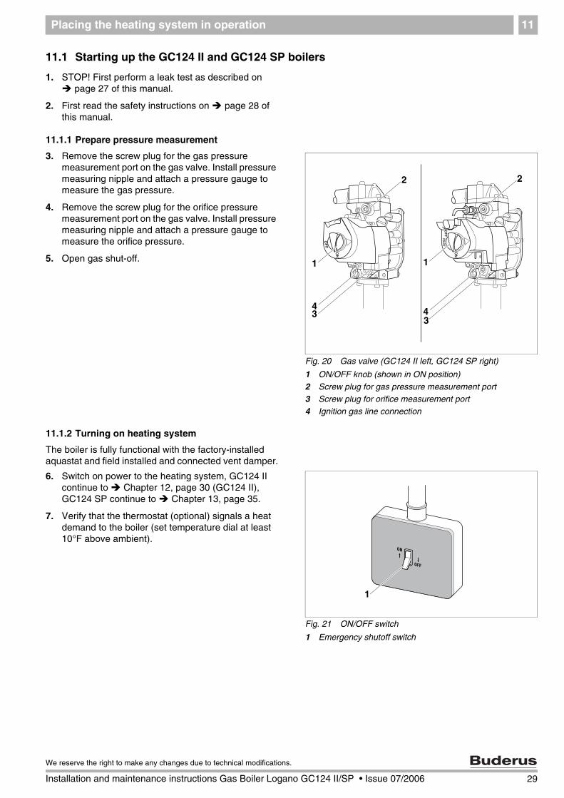
3. Remove the screw plug for the gas pressure measurement port on the gas valve. Install pressure measuring nipple and attach a pressure gauge to measure the gas pressure.
4. Remove the screw plug for the orifice pressure measurement port on the gas valve. Install pressure measuring nipple and attach a pressure gauge to measure the orifice pressure.
5. Open gas shut-off.
11.1.2 Turning on heating system
The boiler is fully functional with the factory-installed aquastat and field installed and connected vent damper.
6. Switch on power to the heating system, GC124 II continue to Chapter 12, page 30 (GC124 II), GC124 SP continue to Chapter 13, page 35.
7. Verify that the thermostat (optional) signals a heat demand to the boiler (set temperature dial at least 10°F above ambient).
Fig. 20 Gas valve (GC124 II left, GC124 SP right)
1 ON/OFF knob (shown in ON position)
2 Screw plug for gas pressure measurement port3 Screw plug for orifice measurement port
4 Ignition gas line connection
1
2
34
1
2
34
Fig. 21 ON/OFF switch
1 Emergency shutoff switch
1
29
We reserve the right to make any changes due to technical modifications.
Installation and maintenance instructions Gas Boiler Logano GC124 II/SP • Issue 07/2006
Final start-up procedures for GC124 II models12
12 Final start-up procedures for GC124 II models
Verifying the ignition spark
1. Look through the sight glass at the igniter and verify that a spark is visible.
2. Should no spark be visible continue to troubleshooting in Chapter 16.8, page 55.
3. Turn ON/OFF knob ( Fig. 23) counterclockwise to the ON position.
4. The ignition flame will appear and ignite the main burner. If the main burner does not ignite, close the gas shut-off. Disconnect heating system from the power source and inform your customer service technician or gas company.
Fig. 22 GC124 II boile
1 Sight glass
1
Fig. 23 GC124 II gas valve
1 ON/OFF knob (shown in ON position)
1
WARNING!
RISK TO LIFE
from fire or explosion.
Never use excessive force on the ON/OFF knob ( Fig. 23).
Turn ON/OFF knob only by hand.
Never use tools to turn knob.
If you are unable to turn the knob by hand, do not try to repair it.
Call Buderus technical service for assistance.
30 Installation and maintenance instructions Gas Boiler Logano GC124 II/SP • Issue 07/2006
We reserve the right to make any changes due to technical modifications.
Final start-up procedures for GC124 II models 12
Checking gas supply pressure
5. Check the gas supply pressure while the boiler is operating. The connection pressure for natural gas must be between 4.7" and 10.5" W.C. For propane gas (LP) it must be between 11" and 13" W.C. If the gas pressure is in the correct range, record the measured value in the start-up protocol, then continue with step 6. If the supply pressure does not meet the above criteria, close gas line and contact the gas company.
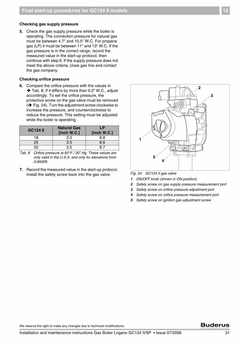
Checking orifice pressure
6. Compare the orifice pressure with the values in Tab. 8. If it differs by more than 0.2" W.C., adjust
accordingly. To set the orifice pressure, the protective screw on the gas valve must be removed ( Fig. 24). Turn the adjustment screw clockwise to increase the pressure, and counterclockwise to reduce the pressure. This setting must be adjusted while the boiler is operating.
7. Record the measured value in the start-up protocol. Install the safety screw back into the gas valve. Fig. 24 GC124 II gas valve
1 ON/OFF knob (shown in ON position)
2 Safety screw on gas supply pressure measurement port
3 Safety screw on orifice pressure adjustment port4 Safety screw on orifice pressure measurement port
5 Safety screw on ignition gas adjustment screw
1
2
45
3
GC124 IINatural Gas[inch W.C.]
LP[inch W.C.]
18 3.5 8.825 3.5 8.632 3.5 8.7
Tab. 8 Orifice pressure at 60°F / 30" Hg. These values are only valid in the U.S.A. and only for elevations from 0-8500ft.
31
We reserve the right to make any changes due to technical modifications.
Installation and maintenance instructions Gas Boiler Logano GC124 II/SP • Issue 07/2006
Final start-up procedures for GC124 II models12
8. Observe main burner flame through the sight glass ( Fig. 22, page 30) in the burner plate. The flame must show a steady and stable body and generally be of bluish color. If the main burner flame meets the requirements, proceed to step 9. If the main burner flame is weak, yellow, or goes out, turn the ON/OFF knob ( Fig. 26) on the gas valve clockwise to OFF. Close the gas shut-off and disconnect the heating system from the main power source and contact the customer service technician or the gas company.
Checking flame rod
9. Test the flame rod by closing the gas shut-off. The main burner flame ( Fig. 25) and the ignition flame are extinguished. After no more than six (6) seconds the main gas solenoid valve on the gas valve must close with an audible noise. If the gas valve does not operate correctly, turn ON/OFF knob on the gas valve clockwise to the OFF position immediately. Close the main gas shut-off and disconnect the heating system from the main power source and contact the customer service technician or the gas company.
10. After 90 seconds the igniter stops generating sparks for five (5) seconds.
11. Disconnect the heating system from the main power source. Open main gas shut-off. A normal operating cycle must follow.
12. If the main burner flame lights and burns to spec, proceed to step 13. If not, turn knob on gas valve clockwise to OFF position immediately. Close main gas shut-off. Disconnect heating system from the power source and inform the customer service technician or gas company.
13. Turn gas valve ON/OFF knob clockwise to OFF position.
14. Close main gas shut-off.
15. Disconnect heating system from the power source and set the thermostat to the lowest setting.
16. Remove pressure measuring nipple and pressure gauge for measuring gas pressure and orifice pressure from the gas valve, and close the openings with the screw plugs.
Fig. 25 Main burner
1 Main burner flame
1
Fig. 26 GC124 II gas valve
1 ON/OFF knob (shown in ON position)
1
32 Installation and maintenance instructions Gas Boiler Logano GC124 II/SP • Issue 07/2006
We reserve the right to make any changes due to technical modifications.
Final start-up procedures for GC124 II models 12
Checking for leaks
17. Open main gas shut-off.
18. Set thermostat at least 10°F above ambient to establish a heat demand.
19. Turn main power switch ON.
20. Turn gas valve ON/OFF knob counterclockwise to ON position.
21. After the burner has lit check the gas valve including screw plugs for leaks using soapy water. If no leaks are found, continue with step 23. If leaks are found, close gas shut-off and turn ON/OFF knob on gas valve clockwise to the OFF position. Disconnect the heating system from the power source and turn thermostat to its lowest setting.
22. Seal leaks. Repeat steps 17 to 21.
23. Carefully wipe away the soapy water to prevent corrosion caused by the alkaline content of the soap.
Checking the vent damper
24. Check the position of the vent damper. The damper must be fully open (vertical). When burner is on flue gases must not escape from the open draft hood.
Fig. 27 Checking vent damper
1 Open draft hood
2 Vent connection3 Vent damper
4 Damper blade position indicator
5 Vent damper motor6 Flue gas collector
7 Boiler
5
6
7
4
3
1
2
WARNING!
RISK OF LIFE
due to leaking flue gases.
Verify the functionality and operability of the vent damper.
33
We reserve the right to make any changes due to technical modifications.
Installation and maintenance instructions Gas Boiler Logano GC124 II/SP • Issue 07/2006
Final start-up procedures for GC124 II models12
Checking aquastat
Check the function of the maximum aquastat to make sure that it switches the boiler off as soon as the boiler water temperature set at the aquastat is reached. Record the result in the start-up protocol.
25. Set aquastat to its desired setting.
26. Replace front door and close.
Fig. 28 Checking aquastat
1 Adjustment knob
1
34 Installation and maintenance instructions Gas Boiler Logano GC124 II/SP • Issue 07/2006
We reserve the right to make any changes due to technical modifications.
Final start-up procedure for GC124 SP models 13
13 Final start-up procedure for GC124 SP models
Lighting pilot
1. Turn gas valve ON/OFF switch counterclockwise to "PILOT" position ( Fig. 30).
2. Press and hold red pilot ignition button in completely.
3. Ignite the pilot burner with the supplied match holder and a burning match through the sight glass in the burner housing.
4. After the pilot burner ignites, continue to hold the red reset button for about a minute.
5. Release red pilot ignition button.
6. The red pilot ignition button must pop up and the pilot burner must continue burning.
7. If the ignition burner goes out, turn ON/OFF switch on gas valve clockwise to OFF and repeat steps 1 through 5.
Fig. 29 GC124 SP boiler
1 Sight glass2 Thermocouple
1
2
WARNING!
RISK TO LIFE
from fire or explosion.
Never use excessive force on the ON/OFF knob ( Fig. 23).
Turn ON/OFF knob only by hand.
Never use tools to turn knob.
If you are unable to turn the knob by hand, do not try to repair it.
Call Buderus technical service for assistance.
Fig. 30 GC124 SP gas valve
1 Safety screw for igniter orifice pressure setting
2 ON/OFF knob (in ON position)
3 Red pilot ignition button4 Screw plug for gas pressure measurement port
5 Safety screw for orifice pressure setting
6 Screw plug for orifice measurement port
2
4
6
1
5
3
WARNING!
RISK TO LIFE
due to poisoning by leaking gas.
If the red pilot ignition button does not pop up when you release it, STOP and do the following:
Close gas shut-off immediately to prevent gas from leaking.
Contact your service technician or gas supplier immediately and have the fault repaired.
35
We reserve the right to make any changes due to technical modifications.
Installation and maintenance instructions Gas Boiler Logano GC124 II/SP • Issue 07/2006
Final start-up procedure for GC124 SP models13
8. If the ignition burner continues to go out after several attempts, turn the ON/OFF knob on the gas valve to OFF immediately to prevent gas from leaking. Check ignition gas line for leaks with soapy water. If no leaks are found, continue with step 9. If leaks have been found, turn ON/OFF knob on gas valve ( Fig. 31) clockwise to the "OFF" position.
9. Seal leaks. Repeats steps 1 to 8.
10. The gas valve ON/OFF knob ( Fig. 31) can only be set to ON if the red pilot ignition button is out. Turn main power switch of the heating system ON.
11. Verify that the thermal element responds to heat.
12. The ignition flame must ignite the main burner. If the main burner does not ignite, close the gas shut-off. Disconnect heating system from the power source and inform your customer service technician or gas company.
Checking gas supply pressure
13. Check the gas supply pressure while the boiler is operating. The supply pressure for natural gas must be between 4.7" and 10.5" W.C. For propane gas (LP) it must be between 11" and 13" W.C. If the gas pressure is in the correct range, record the measured value in the start-up protocol, then continue with step 14. If the supply pressure does not meet the above criteria, close gas line and contact the gas company.
Checking manifold pressure
14. Compare the manifold pressure with the values in Tab. 9. If it differs by more than 0.2" W.C., adjust
accordingly. To set the manifold pressure, the protective screw on the gas valve must be removed ( Fig. 32). Turn the adjustment screw clockwise to increase the pressure, and counterclockwise to reduce the pressure. This setting must be adjusted while the boiler is operating.
15. Record the measured value in the start-up protocol. Install the safety screw back into the gas valve.
Fig. 31 GC124 SP gas valve
1 ON/OFF knob (Shown in ON position)
1
Fig. 32 Gasarmatur GC124 SP
1 Safety screw for igniter manifold pressure setting
2 ON/OFF knob (shown in the "ON" position)3 Red pilot ignition button
4 Screw plug for gas pressure measurement port
5 Safety screw for manifold pressure setting6 Screw plug for manifold measurement port
2
4
6
1
5
3
GC124 SPNatural Gas[inch W.C.]
LP[inch W.C.]
18 3.5 8.825 3.5 8.632 3.5 8.7
Tab. 9 Manifold pressure at 60°F / 30" Hg. These values are only valid in the U.S.A. and only for elevations from 0-8500ft.
36 Installation and maintenance instructions Gas Boiler Logano GC124 II/SP • Issue 07/2006
We reserve the right to make any changes due to technical modifications.
Final start-up procedure for GC124 SP models 13
16. Observe main burner flame through the sight glass( Fig. 29, page 35) in the burner plate. The flame must have a steady and fixed contour and generally has a bluish color. If the main burner flame meets the requirements, proceed with step 17. If the main burner flame is too weak or is yellow or goes out, turn the ON/OFF knob ( Fig. 34) on the gas valve clockwise to OFF. Close the gas shut-off and disconnect the heating system from the power supply and contact the customer service technician or the gas company.
Check flame rod
17. Turn gas valve ON/OFF knob ( Fig. 34) clockwise to OFF position.The main burner flame and the ignition flame are extinguished.
18. Turn gas valve ON/OFF knob ( Fig. 34) counterclockwise to PILOT position.
19. Wait three (3) minutes and turn gas valve ON/OFF knob ( Fig. 34) counterclockwise to ON position.
20. Gas must not flow into the main burner. Use a pressure gauge to check that the manifold pressure (output pressure) is 0.
21. If gas flows turn gas valve ON/OFF knob ( Fig. 34) to OFF position immediately to close the gas valve. Disconnect heating system from the power source and inform your customer service technician or gas company. If no gas flows continue with step 22.
22. Turn gas valve ON/OFF knob clockwise to OFF position.
23. Close main gas shut-off.
24. Disconnect the heating system from the power source.
25. Remove pressure measuring nipple and pressure gauge for measuring gas pressure and manifold pressure from the gas valve and close the openings with the screw plugs.
Fig. 33 Main burner
1 Main burner flame
1
Fig. 34 GC124 SP gas valve
1 ON/OFF knob (in ON position)
1
37
We reserve the right to make any changes due to technical modifications.
Installation and maintenance instructions Gas Boiler Logano GC124 II/SP • Issue 07/2006
Final start-up procedure for GC124 SP models13
Carrying out leak test
26. Open main gas shut-off.
27. Set thermostat at least 10°F above ambient to establish a heat demand.
28. Turn on ON/OFF switch (Emergency shutoff switch).
29. Repeat steps 1 to 5 on page 35.
30. After the burner has lit check the gas valve including screw plugs for leaks using soapy water. If no leaks are found, continue with step 32. If leaks are found, close gas valve and turn ON/OFF knob on gas valve clockwise to the OFF position. Disconnect the heating system from the power source and turn thermostat to its lowest setting.
31. Seal any leaks. Repeat steps 26 to 30.
32. Carefully wipe away the soapy water to prevent corrosion caused by the alkaline content of the soap.
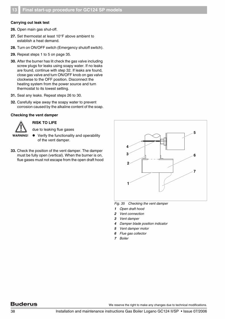
Checking the vent damper
33. Check the position of the vent damper. The damper must be fully open (vertical). When the burner is on, flue gases must not escape from the open draft hood
Fig. 35 Checking the vent damper
1 Open draft hood
2 Vent connection3 Vent damper
4 Damper blade position indicator
5 Vent damper motor6 Flue gas collector
7 Boiler
5
6
7
4
3
1
2
WARNING!
RISK TO LIFE
due to leaking flue gases
Verify the functionality and operability of the vent damper.
38 Installation and maintenance instructions Gas Boiler Logano GC124 II/SP • Issue 07/2006
We reserve the right to make any changes due to technical modifications.
Final start-up procedure for GC124 SP models 13
Checking the Aquastat
Check the function of the maximum aquastat to make sure that it switches the boiler off as soon as the boiler water temperature set at the aquastat is reached. Record the result in the start-up protocol.
34. Set the aquastat to its desired setting
35. Replace front door and close
Fig. 36 Checking aquastat
1 Adjustment knob
1
39
We reserve the right to make any changes due to technical modifications.
Installation and maintenance instructions Gas Boiler Logano GC124 II/SP • Issue 07/2006
Start-up protocol14
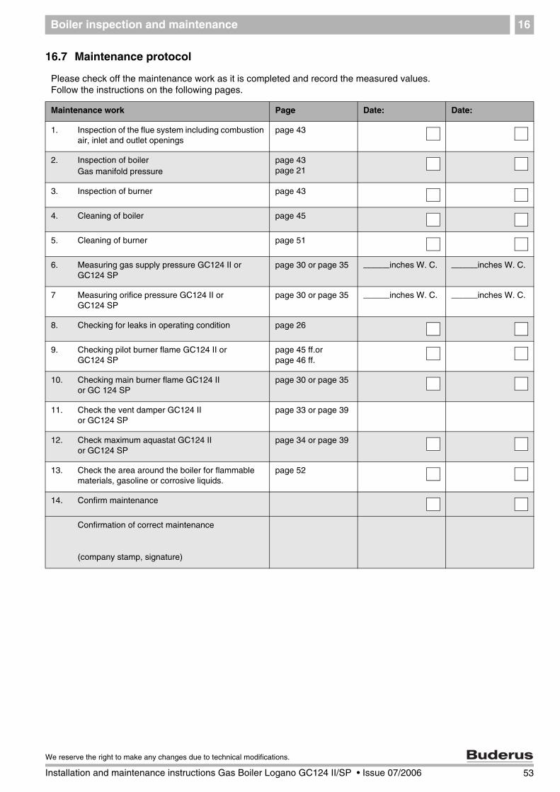
14 Start-up protocol
Please check off all startup steps and record measurements in the appropriate tables.
Start-up procedure Remarks or measured values
1. Type of gas Natural gas LP
2. Has the leak test been completed?
3. Check combustion air, inlet and outlet openings and flue gas connection
4. Check the equipment (correct orifices? See below)and convert gas type if necessary
5. Fill boiler with water and bleed complete heating system
6. Measure gas supply pressure (flow pressure) ––––––––––––––––––– inches W. C.
7. Measure manifold pressure and adjust if necessary ––––––––––––––––––– inches W. C.
8. Check pilot and main burner flame
9. Leak check in operating status
10 Correct functioning of the venting system
11 Check maximum aquastat setting
12 Install front boiler door
13. Inform operator, hand over technical documentation
14. Installer:
Operator:
Signature:__________________
Signature:__________________
USER NOTE
Inform the customer of the correct fuel and enter it in the table (operating manual of boiler).
40 Installation and maintenance instructions Gas Boiler Logano GC124 II/SP • Issue 07/2006
We reserve the right to make any changes due to technical modifications.
Start-up protocol 14
14.1 Informing the owner/operator and handing over technical documentation
Inform the owner/operator of the operation of the complete heating system and the operating instructions for the boiler. The heating contractor shall instruct and demonstrate the start-up and shut-down procedure of the boiler to the owner/operator. Please instruct the owner/operator how to proceed in case of a fire. Sign the protocol on page 40 with the owner and hand over the technical documentation.
41
We reserve the right to make any changes due to technical modifications.
Installation and maintenance instructions Gas Boiler Logano GC124 II/SP • Issue 07/2006
42 Installation and maintenance instructions Gas Boiler Logano GC124 II/SP • Issue 07/2006
We reserve the right to make any changes due to technical modifications.
Taking the heating system out of operation15
15 Taking the heating system out of operation
15.1 Normal system shut-down
1. Turn ON/OFF switch (emergency shutoff switch) to OFF position. This shuts off power to the boiler and all of its components (e.g. burner, aquastat).
2. Turn ON/OFF knob on gas valve clockwise to OFF position.
15.2 Emergency shut-down procedures
Inform the owner and operator of the procedure in case of emergency:
1. Never put yourself at risk. Your own safety must always take priority.
2. Shut off main gas supply.
3. Shut down the heating system using the boiler emergency shutoff switch or the corresponding circuit-breaker.
Fig. 37 Emergency shut-down
1 ON/OFF switch (Emergency shutoff switch)
1
CAUTION!
SYSTEM DAMAGE
due to freezing.
The heating system can freeze up in cold weather if it is shut down.
Leave the heating system switched ON constantly as much as possible.
Protect the heating system from freezing by draining the boiler and water pipes at the lowest point.
Boiler inspection and maintenance 16
16 Boiler inspection and maintenance
16.1 Why is regular maintenance important?
Heating systems require regular maintenance for the following reasons:
– to maintain high efficiency operation and to operate the heating system economically (low fuel consump-tion),
– to sustain safe operation,
– to maintain combustion at an environmentally re-sponsible level.
– to ensure trouble-free operation and long life.
All maintenance work must be carried out by a qualified boiler technician. When replacing components use only parts approved by Buderus. Maintenance is required once a year. Record the results of the inspection in the protocol on page 53.
16.2 Testing the flue system, including combustion air, air inlets and Ventilation openings
Check the venting system, including the combustion air, inlet and outlet openings. All faults must be repaired im-mediately. Make sure that the combustion air feed and the inlets and outlets are not blocked at any point.
16.3 Inspection of the boiler and burner
1. Visually check the boiler and burner for external dirt.
2. If dirt is found, clean boiler and burner.
USER NOTE
Spare parts can be ordered from the spare parts catalog.
43
We reserve the right to make any changes due to technical modifications.
Installation and maintenance instructions Gas Boiler Logano GC124 II/SP • Issue 07/2006
Boiler inspection and maintenance16
16.4 Preparing boiler for cleaning
1. Take the boiler out of operation ( Chapter 15.1, page 42).
2. Open and remove front door of boiler ( Fig. 19, page 27).
3. Turn gas valve ON/OFF knob clockwise to OFF position. Do not use force.
WARNING!
RISK TO LIFE
from electric shock.
Before opening a unit: disconnect elec-trical power and lock to prevent acci-dental reactivation.
WARNING!
RISK TO LIFE
from explosion of flammable gases.
Never work on gas lines unless you are licensed for this type of work
Fig. 38 Gas valve (GC124 II left, GC124 SP right)
1 ON/OFF knob (shown in ON position)
1 1
WARNING!
RISK TO LIFE
from explosion of flammable gases.
Wait five (5) minutes until all gas resi-dues have dissipated. Check whether there is any smell of gas, including at floor level. If there is a gas odor, shut of main gas valve immediately. Turn off power to the heating system and call your customer service technician or gas company.
44 Installation and maintenance instructions Gas Boiler Logano GC124 II/SP • Issue 07/2006
We reserve the right to make any changes due to technical modifications.
Boiler inspection and maintenance 16
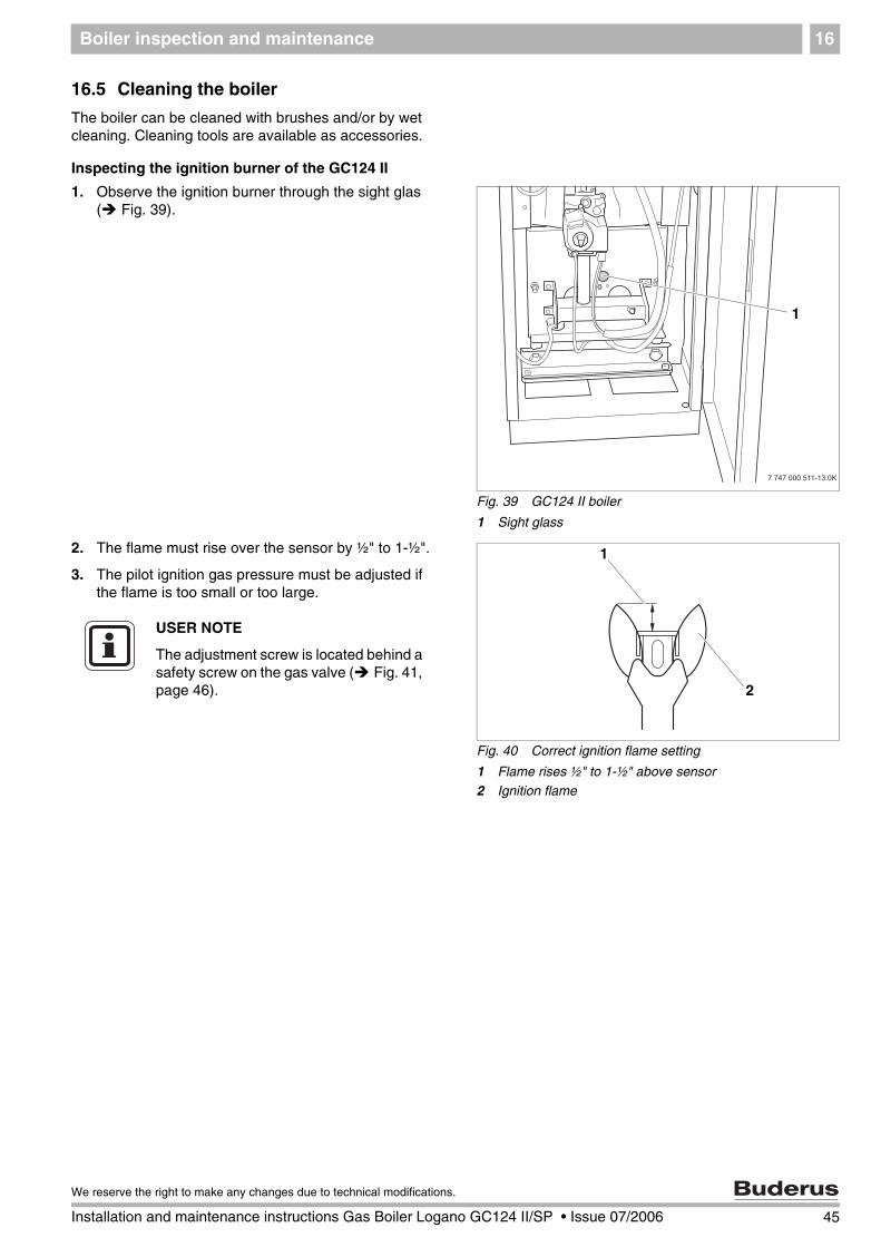
16.5 Cleaning the boiler
The boiler can be cleaned with brushes and/or by wet cleaning. Cleaning tools are available as accessories.
Inspecting the ignition burner of the GC124 II
1. Observe the ignition burner through the sight glas ( Fig. 39).
2. The flame must rise over the sensor by ½" to 1-½".
3. The pilot ignition gas pressure must be adjusted if the flame is too small or too large.
The adjustment screw is located behind a safety screw on the gas valve ( Fig. 41, page 46).
45
We reserve the right to make any changes due to technical modifications.
Installation and maintenance instructions Gas Boiler Logano GC124 II/SP • Issue 07/2006
Boiler inspection and maintenance16
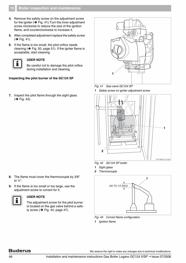
4. Remove the safety screw on the adjustment screw for the igniter ( Fig. 41).Turn the inner adjustment screw clockwise to reduce the size of the ignition flame, and counterclockwise to increase it.
5. After completed adjustment replace the safety screw ( Fig. 41).
6. If the flame is too small, the pilot orifice needs cleaning ( Fig. 50, page 51). If the igniter flame is acceptable, start cleaning.
Inspecting the pilot burner of the GC124 SP
7. Inspect the pilot flame through the sight glass ( Fig. 43).
8. The flame must cover the thermocouple by 3/8" to ½".
9. If the flame is too small or too large, use the adjustment screw to correct for it.
Fig. 41 Gas valve GC124 SP
1 Safety screw on igniter adjustment screw
1
USER NOTE
Be careful not to damage the pilot orifice during installation and cleaning.
Fig. 42 GC124 SP boiler
1 Sight glass
2 Thermocouple
1
2
Fig. 43 Correct flame configuration
1 Ignition flame
2
1
USER NOTE
The adjustment screw for the pilot burner is located on the gas valve behind a safe-ty screw ( Fig. 44, page 47).
46 Installation and maintenance instructions Gas Boiler Logano GC124 II/SP • Issue 07/2006
We reserve the right to make any changes due to technical modifications.
Boiler inspection and maintenance 16
10. Remove protective screw on adjustment screw for pilot burner ( Fig. 44) Turn inner screw clockwise to reduce the size of the pilot burner flame. Turn the inner screw counterclockwise to increase the pilot burner flame.
11. After completed adjustment replace the safety screw ( Fig. 44).
12. If the flame is too small, the pilot orifice needs cleaning ( Fig. 44). If the pilot flame is acceptable, start cleaning.
16.5.1 Cleaning the boiler with brushes
Burner removal:
13. Before opening a unit: disconnect electrical power and lock to prevent accidental reactivation.
14. Close main gas shut-off.
Fig. 44 Gas valve GC124 SP
1 Safety screw on pilot adjustment screw
1
USER NOTE
Be careful not to damage the pilot orifice during installation and cleaning.
WARNING!
RISK TO LIFE
from electric shock.
If cables are connected incorrectly the system may not operate correctly with possibly dangerous consequences.
After maintenance test the heating sys-tem for proper function.
WARNING!
RISK TO LIFE
from electric shock.
Before opening a unit: disconnect elec-trical power and lock to prevent acci-dental reactivation.
47
We reserve the right to make any changes due to technical modifications.
Installation and maintenance instructions Gas Boiler Logano GC124 II/SP • Issue 07/2006
Boiler inspection and maintenance16
15. Secure gas manifold with wire or cord.
16. GC124 II only: Remove igniter cable from ignition module ( Fig. 45).
17. Disconnect cable connector from bottom of gas valve ( Fig. 45).
18. Label cables to the flame roll-out switch, then remove cable. ( Fig. 45).
Fig. 45 Front view (GC124 II top, GC124 SP bottom)
7 Igniter cable (GC124 II only) 8 Gas valve cable connector
9 Pilot line
10 Igniter cable (GC124 II only) or Thermocouple cable (GC124 SP only)
GC124 II
GC124 SP
1
10
4
98
2
7
5
6
3
2 1
3
4
5
89
10
48 Installation and maintenance instructions Gas Boiler Logano GC124 II/SP • Issue 07/2006
We reserve the right to make any changes due to technical modifications.
Boiler inspection and maintenance 16
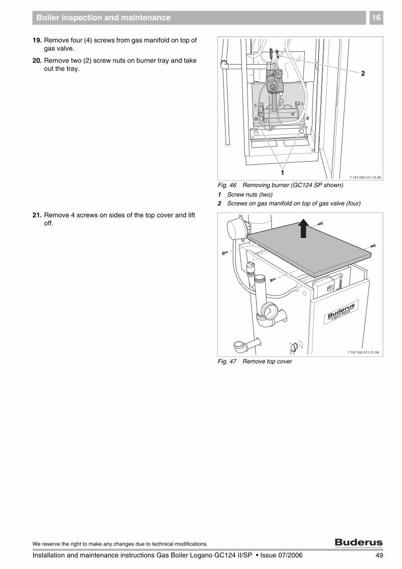
19. Remove four (4) screws from gas manifold on top of gas valve.
20. Remove two (2) screw nuts on burner tray and take out the tray.
21. Remove 4 screws on sides of the top cover and lift off.
Fig. 46 Removing burner (GC124 SP shown)
1 Screw nuts (two)2 Screws on gas manifold on top of gas valve (four)
2
1
Fig. 47 Remove top cover
49
We reserve the right to make any changes due to technical modifications.
Installation and maintenance instructions Gas Boiler Logano GC124 II/SP • Issue 07/2006
Boiler inspection and maintenance16
22. Remove top boiler insulation.
23. Unscrew cleaning cover from the venting manifold.
24. Cover control with foil to prevent entry of metal dust into the control.
25. Use boiler brush to clean out flue gas passages.
26. Clean combustion chamber and bottom insulation.
27. Replace cleaning cover, install screws, and replace insulation.
16.5.2 Wet cleaning (chemical cleaning)
For wet cleaning use a suitable cleaning agent depend-ing on the degree of build-up of dirt (soot or scale).
Use the same procedure as described for cleaning with brushes ( Chapter 16.5.1, page 47).
28. Cover control with foil to prevent entry of spray into the control.
29. Ventilate boiler room well during cleaning.
30. Spray flue gas vents evenly with the cleaning agent.
31. Replace and install the burner in reverse order of removal and disassembly.
32. Place the heating system in operation.
33. Heat the boiler water to a temperature of at least 122°F.
34. Take the boiler out of operation.
35. Allow boiler to cool.
36. Remove burner.
37. Brush out flue gas passages.
38. Clean combustion chamber and bottom insulation.
39. Continue to ventilate boiler room well.
40. Install burner.
41. Reattach boiler jacket.
Fig. 48 Clean out the gas passages
1 Cleaning brush2 Insulation
3 Foil
1 2
3
2
12
3
USER NOTE
Observe the directions for use of the cleaning agent. In some case you may need use a different procedure from that described here.
Fig. 49 Wet cleaning boiler
50 Installation and maintenance instructions Gas Boiler Logano GC124 II/SP • Issue 07/2006
We reserve the right to make any changes due to technical modifications.
Boiler inspection and maintenance 16
16.6 Cleaning the burner
1. Remove burner ( page 47).
2. Check burner rods for dirt. If necessary, clean burner as described below.
3. Unscrew ignition burner unit from burner.
4. Disconnect ignition gas line from ignition burner unit.
5. Remove ignition gas jet and blow out.
6. Immerse burner rods in water with cleaning agent and brush off.
7. Rinse out burner rods with a water jet; hold burner so water enters all slots of the burner rods and drains back out.
8. Remove remaining water by moving the burner back and forth.
9. Verify that the slots of the burner rods are clear. Remove all water and dirt residue from the slots. If any slots are damaged the burner must be replaced.
10. Check igniter (GC124 II only) or pilot burner and thermocouple(GC124 SP only) for damage and signs of corrosion. Replace if necessary.
Inspection of the pilot flame
11. For GC124 II: Repeat steps 1 to 6, page 45 ff.
12. For GC124 SP: Repeat steps 7 to 12, page 46 ff.
13. Assemble and install the burner in reverse order of removal and disassembly. ( page 47).
Fig. 50 Ignition burner (GC124 II left, GC124 SP right)
1 Ignition cable
2 Ignition electrode
3 Ignition gas line4 Ignition gas line screw
5 Thermocouple
1
33
2
44
5
USER NOTE
Be careful not to damage the pilot orifice during installation and cleaning.
Ensure that the insulation on the burner shield, the gas valve, and the controls do not get wet.
Fig. 51 Moving burner back and forth to remove water
USER NOTE
Be careful not to damage the pilot orifice during installation and cleaning.
51
We reserve the right to make any changes due to technical modifications.
Installation and maintenance instructions Gas Boiler Logano GC124 II/SP • Issue 07/2006
Boiler inspection and maintenance16
Performing final checks
14. Place boiler in operation as directed in Chapter 11, page 26 to page 29.
15. For GC124 II: Follow instructions in Chapter 12, page 30 to page 34.
16. For GC124 SP: Follow instructions in Chapter 13, page 35 bis page 39.
17. Test low water alarm if installed.
18. Check area around boiler for hazards.
Complete the maintenance protocol to confirm that all maintenace work has been conducted. Sign the mainte-nance protocol and discuss it with the owner of the heat-ing system.
WARNING!
RISK OF FIRE
From flammable material or liquids.
The area around the boiler must be free from flammable substances, gasoline or any other flammable or corrosive va-pors and liquids.
Maintain a minimum distance of 15 inches around the boiler.
WARNING!
RISK TO LIFE
from explosion of flammable gases.
After maintenance work leaks can oc-cur in pipes and threaded fastenings.
Make a thorough check for leaks.
Use only approved leak testing agents to search for leaks.
52 Installation and maintenance instructions Gas Boiler Logano GC124 II/SP • Issue 07/2006
We reserve the right to make any changes due to technical modifications.
Boiler inspection and maintenance 16
16.7 Maintenance protocol
Please check off the maintenance work as it is completed and record the measured values. Follow the instructions on the following pages.
Maintenance work Page Date: Date:
1. Inspection of the flue system including combustionair, inlet and outlet openings
page 43
2. Inspection of boilerGas manifold pressure
page 43page 21
3. Inspection of burner page 43
4. Cleaning of boiler page 45
5. Cleaning of burner page 51
6. Measuring gas supply pressure GC124 II orGC124 SP
page 30 or page 35 –––––––inches W. C. –––––––inches W. C.
7 Measuring orifice pressure GC124 II orGC124 SP
page 30 or page 35 –––––––inches W. C. –––––––inches W. C.
8. Checking for leaks in operating condition page 26
9. Checking pilot burner flame GC124 II orGC124 SP
page 45 ff.or page 46 ff.
10. Checking main burner flame GC124 II or GC 124 SP
page 30 or page 35
11. Check the vent damper GC124 II or GC124 SP
page 33 or page 39
12. Check maximum aquastat GC124 II or GC124 SP
page 34 or page 39
13. Check the area around the boiler for flammable materials, gasoline or corrosive liquids.
page 52
14. Confirm maintenance
Confirmation of correct maintenance
(company stamp, signature)
53
We reserve the right to make any changes due to technical modifications.
Installation and maintenance instructions Gas Boiler Logano GC124 II/SP • Issue 07/2006
Boiler inspection and maintenance16
Datum: Datum: Datum: Datum: Datum:
–––––––inches W. C –––––––inches W. C –––––––inches W. C –––––––inches W. C –––––––inches W. C
–––––––inches W. C –––––––inches W. C –––––––inches W. C –––––––inches W. C –––––––inches W. C
54 Installation and maintenance instructions Gas Boiler Logano GC124 II/SP • Issue 07/2006
We reserve the right to make any changes due to technical modifications.
Boiler inspection and maintenance 16
16.8 Troubleshooting the GC124 II
Equipment required: Wiring diagrams ( Chapter 19, page 80) and voltage detectors for 120 VAC and 24 VAC.
Start
Close gas shut-off. Set thermo-stat (control) to require heat (vent damper open). Switch on power.
Observe ignition sparks in gap between electrode and sensor through sight glass.
• Check electrical power source, low-voltage transformer, thermostat (con-trol) and wiring. Check that the vent damper is open and the limit switch is present.
No
No
NoOpen main gas shut-off. Ignition flame is burning.
• Check that all manually operated gas shut-offs are open; check that gas connections and pressures are correct and that pilot orifice is not blocked.
• Check electrical connection between ignition module and pilot burner.
• If the voltage is correct replace gas valve, otherwise replace automatic ignition module.
NoSystem operates until the heat requirement ends.
• Check ignition wiring and ground for continuity. Note: If the ground is weak or faulty, the system may switch off at random, even if the heating system operates correctly when checked.
• Check that the ignition flame surrounds the electrode and burns evenly with a bluish flame. If OK replace electrode.
• If everything is OK replace ignition module.
NoHeat requirement ended, system switches off, vent damper clos-es.
End of troubleshooting Repeat procedure until heating system operates properly.
• Check that the vent damper operates and limit switches are present. If necessary, replace vent damper.
• Check ignition wiring, ceramic insulator of ignition electrode and ignition gap, adjust if necessary.
• Check the ignition cable contact for signs of scorching or kinking.
• Replace automatic ignition unit.
NoIgnition spark stops as soon as ignition flame burns.
• Check ignition wiring and ground for continuity.
• Check ignition electrode.
• Check electrical connections between ignition electrode and automatic ignition module.
• Check whether the ceramic insulator in the ignition electrode is broken.
• Check that the ignition flame surrounds the electrode and burns steadily with a bluish flame.
• Adjust ignition flame.
• If this does not correct the fault, replace the automatic ignition unit.
NoMain burner ignites.• Use MV-MV/PV terminals to check 24 V alternating current, closed cur-
rent circuit at the automatic ignition. If there is no voltage, replace auto-matic ignition module.
• Check electrical connection between ignition module and gas valve. If OK, replace gas valve.
• Check operation of thermostat (control).
• Disconnect 24V connection to gas valve. If gas valve closes, check ther-mostat and line voltage wiring again.
• If the gas valve does not close, replace gas valve.
55
We reserve the right to make any changes due to technical modifications.
Installation and maintenance instructions Gas Boiler Logano GC124 II/SP • Issue 07/2006
or ignition flame does not burn, au-tomatic ignition starts ignition at-
tempt, switches off after 90 seconds.
END
PHASE 1
Ignition attempt
PHASE 2
Main burner operating
Power interruptionSystem switches off. Does the system restart when power is restored?
Pilot flame faultMain gas valve closes,ignition module starts ignition attempt.
56 Installation and maintenance instructions Gas Boiler Logano GC124 II/SP • Issue 07/2006
We reserve the right to make any changes due to technical modifications.
Boiler inspection and maintenance 16
16.9 Troubleshooting the GC124 SP
Equipment required: Wiring diagrams ( Chapter 19, page 80) and voltage detectors for 120 VAC and 24 VAC.
• Verbindungen zur Gasarmatur prüfen.
• Geht die Zündflamme aus, prüfen, ob das Thermoelement dicht mit den Gasventilen abschließt; wenn ja Thermoelement austauschen.
• Geht die Zündflamme immer wieder aus, Gasventile austauschen.
• Prüfen, ob alle handbetätigten Gasabsperrventile geöffnet, Gasan-schlüsse und Druckmesswerte in Ordnung und Zündgasdüsen nicht ver-stopft sind.
• Check connections to gas valve.
• If the ignition flame goes out, check that the thermocouple is firmly screwed to the gas valve; if yes, replace thermocouple.
• If the ignition flame continues to go out, replace gas valve.
• Check that all manually operated gas shut-offs are open; check that gas connections and pressures are correct and that pilot orifice is not blocked.
Start
Set gas valve ON/OFF knob clockwise to OFF position. Close main gas shut-off. Set thermostat (control) to heat re-quirement (vent damper opens). Switch on power.
Set gas valve ON/OFF knob counterclockwise to PILOT posi-tion. Open main gas shut-off. Press red pilot ignition button and ignite ignition flame. Hold down red pilot ignition button for one minute and then release. Ig-nition flame is burning.
• Check electrical power source, low-voltage transformer, thermostat (con-trol) and wiring. Check that the vent damper is open and the limit switch is present.
No
No
NoSet gas valve ON/OFF knob counterclockwise to ON. Main burner ignites.
• Check 24-V voltage at the gas valve.
• Check electrical connections to gas valve. If OK replace gas valve.
NoSystem operates until the heat requirement ends.
• Check that the ignition flame surrounds the thermocouple and burns evenly with a bluish flame. If OK replace thermocouple.
58 Installation and maintenance instructions Gas Boiler Logano GC124 II/SP • Issue 07/2006
We reserve the right to make any changes due to technical modifications.
Parts lists 17
17 Parts lists
The following spare parts are available for Buderus heating systems. The Buderus article number is listed in the column of the corresponding model if different parts are required for different models. In other cases the quantity of components is shown.
Boiler jacket ( Fig. 52)
Item. #
Description Buderus Part number
Model 18Quantity/
Model
Model 25Quantity/
Model
Model 32Quantity/
Model
10 Front door complete GC124 7747003- 359 360 362
20 Magnet for front door 63043937 1 1 1
30 Logano GC124 name plate 63046605 1 1 1
40 Inner panel 7747000- 765 766 767
50 Side panel left 7747000746 1 1 1
60 Side panel right 7747000748 1 1 1
70 Top cover 7747000- 768 769 770
80 Rear panel 7747000- 761 763 764
90 Insulation front 7747000- 740 741 742
100 Insulation left 7747000743 1 1 1
110 Insulation right 7747000744 1 1 1
120 Insulation top 7747000- 737 738 739
130 Insulation rear 7747000- 734 735 736
140 Cable holdersee mounting
material1 1 1
150 Strain relief straightsee mounting
material1 1 1
160 Cable holder ¼" x ½"see mounting
material3 3 3
170 Cable holder ½"see mounting
material2 2 2
180 Sheet metal screwssee mounting
material17 17 17
Mounting materialsee mounting
material1 1 1
Tab. 10 Boiler jacket
59
We reserve the right to make any changes due to technical modifications.
Installation and maintenance instructions Gas Boiler Logano GC124 II/SP • Issue 07/2006
Parts lists17
Fig. 52 Boiler jacket
BuderusLogano Classic
7747100028-01-Verkleidung GC124 US
10
160
170
40
90
100
110
130
120
180
180
180
180
180
180
60
50
150 160
160
180140
180
180
180
70
80
20
30
60 Installation and maintenance instructions Gas Boiler Logano GC124 II/SP • Issue 07/2006
We reserve the right to make any changes due to technical modifications.
Parts lists 17
Boiler block – attachment parts ( Fig. 53)Item. No.
We reserve the right to make any changes due to technical modifications.
Installation and maintenance instructions Gas Boiler Logano GC124 II/SP • Issue 07/2006
Parts lists17
Fig. 55 Controls for GC124 SP
7747100020-01-Regelung GAW031 US
101112
190
170
160
140
150
130
80
90
90
20
30
30
70
40
50
50
5060
60
60
6050
5060
60
210
220230
250
200
260
200
240
240
270
180
68 Installation and maintenance instructions Gas Boiler Logano GC124 II/SP • Issue 07/2006
We reserve the right to make any changes due to technical modifications.
Parts lists 17
Tab. 14 Burner for GC124 II/SP
Burner assembly for GC124 II/SP ( Fig. 56)Item. No.
Description Buderus Part number
Model 18Quantity/
Model
Model 25Quantity/
Model
Model 32Quantity/
Model
10 Burner complete 7747001213 1 - -
11 Burner complete 7747001214 - 1 -
12 Burner complete 7747001215 - - 1
20 Gasket 05483082 1 1 1
30 Insulation including adhesive 05181396 1 1 1
40 Adhesive for insulation 02037312 1 1 1
50 Diverter 7747000913 1 1 1
60 Screws Torx 7747001217 1 1 1
70 Gasket 05883094 2 3 4
80 Main gas orifice 2.85 mm Natural Gas 05484408 1 - -
81 Main gas orifice 2.75 mm Natural Gas 05484400 - 1 -
82 Main gas orifice 2.70 mm Natural Gas 05484396 - - 1
83 Main gas orifice 1.80 mm Liquid Propane 05484340 1 - -
84 Main gas orifice 1.75 mm Liquid Propane 05484336 - 1 -
85 Main gas orifice 1.70 mm Liquid Propane 05484332 - - 1
90 Screw 05947712 1 1 1
100 Flame roll-out switch 63034010 1 1 1
110 Holder for match 7747001230 1 1 1
69
We reserve the right to make any changes due to technical modifications.
Installation and maintenance instructions Gas Boiler Logano GC124 II/SP • Issue 07/2006
Parts lists17
Fig. 56 Burner for GC124 II/SP
7747100077-01-Brennrost AE124GC II/SP US
101112
20
70
70
70
70
30
50
808182838485
50
60
6060
60
90 100
40
110
70 Installation and maintenance instructions Gas Boiler Logano GC124 II/SP • Issue 07/2006
We reserve the right to make any changes due to technical modifications.
Parts lists 17
Tab. 15 LP conversion kits
USER NOTE
The complete burner is supplied only in the model for natural gas G20 for 0-8500 feet. If a different model of burner is wanted, the corresponding gas conversion parts must be included in the order. The replaced parts must remain with the heating system for a possible future reconversion.
We reserve the right to make any changes due to technical modifications.
Installation and maintenance instructions Gas Boiler Logano GC124 II/SP • Issue 07/2006
Parts lists17
Fig. 57 Gas conversion kits
7747100076-01-Brennervarianten, Gasartumstellteile AE124GC II/SP US
101112
202122
72 Installation and maintenance instructions Gas Boiler Logano GC124 II/SP • Issue 07/2006
We reserve the right to make any changes due to technical modifications.
Parts lists 17
Tab. 16 Gas valve GC124 II/SP
Gas valve GC124 II/SP ( Fig. 58)Item. No.
Description Buderus Part number
Model 18Quantity/
Model
Model 25Quantity/
Model
Model 32Quantity/
Model
10Gas Supply Pipe elbow ½" NPT incl. gasket and screws
00475908 1 1 1
20 Gas valve VR8204H1006 GC124 II 00475825 1 1 1
25 Gas valve VR8200H1004 GC124 SP 05181446 1 1 1
30 Gasket 05483082 1 1 1
40 Screw for gas valve 63025928 1 1 1
73
We reserve the right to make any changes due to technical modifications.
Installation and maintenance instructions Gas Boiler Logano GC124 II/SP • Issue 07/2006
Parts lists17
Fig. 58 Gas valve GC124 II/SP
7747100078-02-Gasarmatur VR8204H 1006 GC124 II US
10
20
30
40
40
25
74 Installation and maintenance instructions Gas Boiler Logano GC124 II/SP • Issue 07/2006
We reserve the right to make any changes due to technical modifications.
Parts lists 17
Ignition burner GC124 II ( Fig. 59)Item. No.
Description Buderus Part number
Model 18Quantity/
Model
Model 25Quantity/
Model
Model 32Quantity/
Model
10 Igniter burner complete 7747001227 1 1 1
20 Screw set 7747001219 1 1 1
30 Bracket 67900765 1 1 1
40 Pilot orifice, natural gas, BCR20 05181648 1 1 1
41 Pilot orfice, LP, BBR12 05176998 1 1 1
50 Screw nut 05181672 1 1 1
60 Screw Torx 63010217 1 1 1
70 Screw set 7747001217 1 1 1
80 Ignition gas line 7747001228 1 1 1
Tab. 17 Ignition burner GC124 II
75
We reserve the right to make any changes due to technical modifications.
Installation and maintenance instructions Gas Boiler Logano GC124 II/SP • Issue 07/2006
Parts lists17
Fig. 59 Ignition burner GC124 II
7747100080-00-Zündbrenner GC124 Classic II US
10
2030
40
50
8050
50
60
70
41
203040506070
76 Installation and maintenance instructions Gas Boiler Logano GC124 II/SP • Issue 07/2006
We reserve the right to make any changes due to technical modifications.
Parts lists 17
Ignition burner GC124 SP ( Fig. 60)Item. No.
Description Buderus Part number
Model 18Quantity/
Model
Model 25Quantity/
Model
Model 32Quantity/
Model
10 Pilot burner complete 7747001309 1 1 1
20 Screw set 7747001220 1 1 1
30 Bracket 05181451 1 1 1
40 Pilot orifice, Natural gas, CAR 12 05181016 1 1 1
41 Pilot orifice, LP, GAF 8 05181017 1 1 1
50 Screw nut 05181672 1 1 1
60 Screw Torx 63010217 1 1 1
70 Screw set 7747001217 1 1 1
80 Ignition gas line 7747001229 1 1 1
90 Thermocouple 05176988 1 1 1
Tab. 18 Ignition burner GC124 SP
77
We reserve the right to make any changes due to technical modifications.
Installation and maintenance instructions Gas Boiler Logano GC124 II/SP • Issue 07/2006
Parts lists17
Fig. 60 Ignition burner GC124 SP
7747100081-00-Zündbrenner GC124 Classic SP US
10
20
3020
40
50
60
70
50
80
90
50
41
203040506070
78 Installation and maintenance instructions Gas Boiler Logano GC124 II/SP • Issue 07/2006
We reserve the right to make any changes due to technical modifications.
Technical specifications 18
18 Technical specifications
Main gas orifice identification and manifold pressure for Natural gas
Main gas orifice identification and manifold pressure for LP
1) installation altitude
2) Only conver the boiler from natural gas to LP by consulting the conversion instructions
Boiler size Number of orifices Main gas orifice identificationfor elevations from [feet]
Gas supply volume[in ft3/h]
Manifold pressure[inch W.C.]
0–8500 ft1)
18/3 2 285 68.8 3.5
25/4 3 275 95.8 3.532/5 4 270 123.3 3.5
Tab. 19 Main gas orifice identification and manifold pressure for Natural gasat60° F / 30 inch HG.These values are only valid in the U.S.A. and only for elevations from 0–8500 ft gültig.
Boiler size Number of orifices Main gas orifice identificationfor elevations from [feet]
Gas supply volume[in ft3/h]
Manifold pressure[inch W.C.]
0–8500 ft1)
18/3 2 180 29.6 8.825/4 3 175 41.2 8.6
32/5 4 170 53 8.7
Tab. 20 Main gas orifice identification and manifold pressure for Natural gasat 60° F / 30 inch HG.These values are only valid in the U.S.A. and only for elevations from 0–8500 ft gültig.
USER NOTE
If the installation is over 8500 feet above see level, please contact Buderus for another product option as the GC124 is not approved above 8500 feet operation.
Do not attempt to alter this boiler without consulting Buderus.
79
We reserve the right to make any changes due to technical modifications.
Installation and maintenance instructions Gas Boiler Logano GC124 II/SP • Issue 07/2006
Electrical circuit diagrams19
19 Electrical circuit diagrams
Fig. 61 Wiring Diagram– GC124 II
US
white
black
Bloc
ked
vent
sw
itch
white
black
Flam
e ro
ll out
safe
tysh
utof
f swi
tch
Opt
iona
l Ven
tD
ampe
r P
lug
24V
AW
G 1
8 W
IRE
120
VA
C
blac
k
oran
ge
orange
black
blue
yello
w
blac
k
whi
te
120V
24V
Tran
sfor
mer
40V
A
4
Boile
r Sen
sor
WR CS2
S1
R
R B1
L1X
L2
C2
L1
C B2
L2X G C1
Page
: 1/2
Wiri
ng d
iagr
am g
as-b
oile
r GC1
24 U
SA
Inte
rmitt
ent i
gnitio
n
7230
6304
6156
Plug
Plug
PV
Inte
rmitt
ent p
ilot c
ontro
l mod
ule
S860
0H
2006
/07
GAW
030
USA
Con
nect
ing
term
inal
s fo
r the
rmos
tat
( Use
Red
+ W
hite
)2
Aqua
stat
Rel
ayL7
148F
...
2
Burn
er a
ssem
bly
Term
inal
s on
boi
ler b
lock
Mai
n su
pply
pow
er -
use
circ
uit b
reak
eras
requ
ired
by c
ode
1
Inte
rmitt
ent p
ilot d
ual
valve
com
bina
tion
gas
cont
rol V
R820
4...
Pilo
t bur
ner
(Hon
eyw
ell)
Mai
n va
lve
Pilo
t val
ve
gree
n
blue
whi
te
red
GN
D
MV
MV
PV
GNDPV
MV/
PVMV
24V
24V
32
1
Drwg
. no.:
Revie
wed
:
Editio
n :
Wirin
g dia
gram
:
yello
w
whi
te
blac
k
gree
n
Junc
tion
Box
Circ
ulat
or
N H
1
Serv
ice
Switc
h(b
y ot
hers
)
yello
w
whi
te
80 Installation and maintenance instructions Gas Boiler Logano GC124 II/SP • Issue 07/2006
We reserve the right to make any changes due to technical modifications.
Electrical circuit diagrams 19
Fig. 62 Wiring Diagram– GC124 SP
US
white
black
Bloc
ked
vent
sw
itch
white
black
Flam
e ro
ll out
safe
tysh
utof
f swi
tch
120
VA
C
blac
k
oran
ge
orange
black4
Boile
r Sen
sor
Page
: 1/2
Wiri
ng d
iagr
am g
as-b
oile
r GC1
24 U
SA
Stan
ding
pilo
t
7230
6304
6617
Plug
2006
/07
GAW
031
USA
Con
nect
ing
term
inal
s fo
r the
rmos
tat
( Use
Red
+ W
hite
)2
2
Term
inal
s on
boi
ler b
lock
1
Cont
inuo
us p
ilot d
ual
Auto
mat
ic va
lve c
ombi
natio
nga
s co
ntro
l VR8
200.
..
Mai
n va
lve
TRTH
32
1
Drwg
. no.:
Revie
wed
:
Editio
n :
Wirin
g dia
gram
:
gree
n
Opt
iona
l Ven
tD
ampe
r P
lug
blue
yello
w
blac
k
whi
te
120V
24V
Tran
sfor
mer
40V
A
WR CS2
S1
R
R B1
L1X
L2
C2
L1
C B2
L2X G C1
Aqua
stat
Rel
ayL7
148F
...
yello
w
whi
te
blac
k
gree
n
Junc
tion
Box
Circ
ulat
or
N H
1
Serv
ice
Switc
h(b
y ot
hers
)
yello
w
whi
te24
V A
WG
18
WIR
E
Mai
n su
pply
pow
er -
use
circ
uit b
reak
eras
requ
ired
by c
ode
81
We reserve the right to make any changes due to technical modifications.
Installation and maintenance instructions Gas Boiler Logano GC124 II/SP • Issue 07/2006
Electrical circuit diagrams19
Fig. 63 Wiring Diagram– GC124 II
Fig. 64 Wiring Diagram– GC124 SP
82 Installation and maintenance instructions Gas Boiler Logano GC124 II/SP • Issue 07/2006
We reserve the right to make any changes due to technical modifications.
Notes
83
We reserve the right to make any changes due to technical modifications.
Installation and maintenance instructions Gas Boiler Logano GC124 II/SP • Issue 07/2006