INSTALLATION AND SERVICE MANUAL INDOOR GAS-FIRED DUCT FURNACE (NATURAL OR POWER VENTED) (S) DISM-15 J30-05373 Model No. Serial No. FOR YOUR SAFETY The use and storage of gasoline or other flammable vapors and liquids in open containers in the vicinity of this appliance is hazardous. ATTENTION: READ THIS MANUAL AND ALL LABELS ATTACHED TO THE UNIT CAREFULLY BEFORE ATTEMPTING TO INSTALL, OPERATE OR SERVICE THESE UNITS! CHECK UNIT DATA PLATE FOR TYPE OF GAS AND ELECTRICAL SPECIFICATIONS AND MAKE CERTAIN THAT THESE AGREE WITH THOSE AT THE POINT OF INSTALLATION. RECORD THE UNIT MODEL AND SERIAL No.(s) IN THE SPACE PROVIDED. RETAIN FOR FUTURE REFERENCE. FOR YOUR SAFETY If you smell gas: 1. Open windows. 2. Don't touch electrical switches. 3. Extinguish any open flame. 4. Immediately contact your gas supplier. APPROVED FOR USE IN CALIFORNIA WHEN EQUIPPED WITH SPARK IGNITION Install, operate, and maintain unit in accordance with the manufacturer's instructions to avoid exposure to fuel substances, or substances from incomplete combustion, which can cause death or serious illness. The state of California has determined that these substances may cause cancer, birth defects, or other reproductive harm. INSTALLER'S RESPONSIBILITY Installer Please Note: This equipment has been test fired and inspected. It has been shipped free from defects from our factory. However, shipment and installation problems such as loose wires, leaks, or loose fasteners may occur. It is the installer's responsibility to inspect and correct any problem that may be found. Improper installation, adjustment, alteration, service, or maintenance can cause property damage, injury, or death. Read the installation, operating, and maintenance instruction thoroughly before installing or servicing this equipment. RECEIVING INSTRUCTIONS Inspect shipment immediately when received to determine if any damage has occurred to the unit during shipment. After the unit has been uncrated, check for any visible damage to the unit. If any damage is found, the consignee should sign the bill of lading indicating such damage and immediately file claim for damage with the transportation company. www.sterlinghvac.com HVAC PRODUCTS 260 NORTH ELM ST., WESTFIELD, MA 01085 TEL: (413) 564-5540 FAX: (413) 562-5311 MODELS: QV (E) (D,S) (100, 125, 150, 200, 225, 250, 300, 350, 400) (S) Look in direction of air flow to determine if your unit is right or left hand accessible. Models QVS/QVES are available with standard right hand access to service the burner drawer. Left hand is optional. 12/05
Transcript
INSTALLATION AND SERVICE MANUAL
INDOOR GAS-FIRED DUCT FURNACE(NATURAL OR POWER VENTED)
(S) DISM-15J30-05373
Model No. Serial No.
FOR YOUR SAFETYThe use and storage of gasoline or other flammable vapors and liquids in open containersin the vicinity of this appliance is hazardous.
ATTENTION: READ THIS MANUAL AND ALL LABELS ATTACHED TO THE UNIT CAREFULLY BEFOREATTEMPTING TO INSTALL, OPERATE OR SERVICE THESE UNITS! CHECK UNIT DATA PLATE FOR TYPE OF GASAND ELECTRICAL SPECIFICATIONS AND MAKE CERTAIN THAT THESE AGREE WITH THOSE AT THE POINT OFINSTALLATION. RECORD THE UNIT MODEL AND SERIAL No.(s) IN THE SPACE PROVIDED. RETAIN FOR FUTUREREFERENCE.
FOR YOUR SAFETYIf you smell gas:1. Open windows.2. Don't touch electrical switches.3. Extinguish any open flame.4. Immediately contact your gas supplier.
APPROVED FOR USE IN CALIFORNIA WHEN EQUIPPED WITH SPARK IGNITION
Install, operate, and maintain unit in accordance with the manufacturer'sinstructions to avoid exposure to fuel substances, or substances from incompletecombustion, which can cause death or serious illness. The state of California hasdetermined that these substances may cause cancer, birth defects, or otherreproductive harm.
INSTALLER'S RESPONSIBILITYInstaller Please Note: This equipment has been test fired and inspected. It has beenshipped free from defects from our factory. However, shipment and installationproblems such as loose wires, leaks, or loose fasteners may occur. It is the installer'sresponsibility to inspect and correct any problem that may be found.
Improper installation, adjustment, alteration, service, or maintenance cancause property damage, injury, or death. Read the installation, operating, andmaintenance instruction thoroughly before installing or servicing this equipment.
RECEIVING INSTRUCTIONSInspect shipment immediately whenreceived to determine if any damagehas occurred to the unit duringshipment. After the unit has beenuncrated, check for any visibledamage to the unit. If any damage isfound, the consignee should signthe bill of lading indicating suchdamage and immediately file claimfor damage with the transportationcompany.
www.sterlinghvac.com
HVAC PRODUCTS260 NORTH ELM ST., WESTFIELD, MA 01085
Look in direction of air flow to determine if your unit is right or left handaccessible. Models QVS/QVES are available with standard right handaccess to service the burner drawer. Left hand is optional.12/05
2
MODEL TYPE DESIGNATIONFigure 1 = Natural Vented (Standard) Duct Furnace (Bottom Access, Standing Pilot) (Optional Intermittent Pilot)Figure 2 = Natural Vented Side Service Duct Furnace (Side Access, Standing Pilot) (Optional Intermittent Pilot)Figure 3 = Power Vented Duct Furnace (Bottom Access, Rear Vent Position, Spark Ignition)Figure 4 = Side Service Power Vented Duct Furnace (Side Access, Rear Vent Position, Spark Ignition)
TABLE OF CONTENTSGENERAL SAFETY INFORMATION .............................................................................................................. 1, 2, 3DUCT FURNACES (NATURAL AND POWER VENTED)
OPERATIONNatural Vented Units with Standing Pilot ............................................................................... 19, 20Natural Vented Units with Optional Intermittent Pilot ............................................................. 21, 23Power Vented Units with Intermittent Pilot ............................................................................. 22, 23Adjustments ........................................................................................................................... 24, 25Orifice Sizing ................................................................................................................................ 24
MAINTENANCE ........................................................................................................................................ 25COMPONENT PARTS .................................................................................................................. 26, 27, 28
The duct furnace design is certified by CSA Internationalfor use with natural and LP (propane) gases. ANSI andNFPA Standards as well as Canadian installation codesreferred to in this manual are the ones that wereapplicable at the time the design was certified. In addition,the duct furnace may be installed on the downstream sideof a cooling unit, without need of a bypass duct.
If the unit is to be installed at an altitude exceeding 2,000feet (610m) above sea level, derate the input by 4% foreach 1,000 foot (305m) rise above sea level. Specialorifices are required for installations above 2,000 feet(610m).
When units are installed in Canada, any reference toderations at altitudes in excess of 2000 feet (610m) are tobe ignored. At altitudes of 2000 to 4500 feet (610 to1372m), the units must be orificed to 90% of the normalaltitude rating, and be so marked in accordance with theCSA certification.
The following terms are used throughout this manual, inaddition to CSA requirements, to bring attention to thepresence of potential hazards or to important informationconcerning the product:
Indicates an imminently hazardoussituation which, if not avoided, will result in death,serious injury or substantial property damage.
Indicates an imminently hazardoussituation which, if not avoided, could result indeath, serious injury or substantial propertydamage.
Indicates an imminently hazardoussituation which, if not avoided, may result in minorinjury or property damage.
NOTICE: Used to notify of special instructions oninstallation, operation or maintenance which areimportant to equipment but not related to personalinjury hazards.
3
GENERAL SAFETY INFORMATION
Failure to comply with the generalsafety information may result in extensiveproperty damage, severe personal injury or death.
This product must be installed bya licensed plumber or gas fitter when installedwithin the Commonwealth of Massachusetts.
Installation must be made in accordance with localcodes, or in absence of local codes, with the latestedition of ANSI Standard Z223.1 (N.F.P.A. No. 54)National Fuel Gas Code. All of the ANSI and NFPAStandards referred to in these installation instructions arethose that were applicable at the time the design of thisappliance was certified. The ANSI Standards are availablefrom the CSA Information Services, 1-800-463-6727. TheNFPA Standards are available from the National FireProtection Association, Batterymarch Park, Quincy, MA02269. These duct furnaces are designed for use inairplane hangars when installed in accordance withcurrent ANSI/NFPA No. 409 and in public garages wheninstalled in accordance with current NFPA No. 88A andNFPA No. 88B.
If installed in Canada, the installation must conform withlocal building codes, or in absence of local buildingcodes, with CGA-B149.1 “Installation Codes for NaturalGas Burning Appliances and Equipment" or CGA-B149.8“Installation Codes for Propane Gas Burning Appliancesand Equipment”. These indoor duct furnaces have beendesigned and certified to comply with CGA 2.6. Alsosee sections on installation in AIRCRAFT HANGARSand PUBLIC GARAGES.
Do not alter the duct furnace inany way or damage to the unit and/or severepersonal injury or death may occur!
Disconnect all power and gassupplies before installing or servicing the heater.If the power disconnect is out of sight, lock it inthe open position and tag it to prevent unexpectedapplication of power. Failure to do so could resultin fatal electric shock, or severe personal injury.
Insure that all power sources conformto the requirements of the unit heater or damage tothe unit will result!
Follow installation instructions CAREFULLY to avoidcreating unsafe conditions. All wiring should be doneand checked by a qualified electrician, using copper wireonly. All external wiring must conform to applicable localcodes, and to the latest edition of the National ElectricCode ANSI/NFPA No. 70. All gas connections should bemade and leak-tested by a suitably qualified individual,per instructions in this manual.
Also follow procedures listed on the “Gas EquipmentStart-up” sheet located in this manual.
Use only the fuel for which the heater is designed (seerating plate). Using LP gas in a heater that requires naturalgas, or vice versa, will create the risk of gas leaks, carbonmonoxide poisoning and explosion.
Do not attempt to convert theheater for use with a fuel other than the oneintended. Such conversion is dangerous, andcould create unsafe conditions that result in death,serious personal injury or property damage.
Make certain that the power source conforms to theelectrical requirements of the heater.
Do not depend upon a thermostator other switch as sole means of disconnectingpower when installing or servicing heater. Alwaysdisconnect power at main circuit breaker asdescribed above. Failure to do so could result infatal electric shock.
Special attention must be given to any groundinginformation pertaining to this heater. To prevent the risk ofelectrocution, the heater must be securely and adequatelygrounded. This should be accomplished by connecting agrounded conductor between the service panel and theheater. To ensure a proper ground, the grounding meansmust be tested by a qualified electrician.
Do not insert fingers or foreign objects into the heater orits air moving device. Do not block or tamper with theheater in any manner while in operation or just after it hasbeen turned off, as some parts may be hot enough tocause injury.
This heater is intended for general heating applicationsONLY. It must NOT be used in potentially dangerouslocations such as flammable, explosive, chemical-ladenor wet atmospheres.
In cases in which property damage may result frommalfunction of the heater, a backup system or atemperature sensitive alarm should be used.
The open end of piping systems beingpurged shall not discharge into areas where there aresources of ignition or into confined spaces UNLESSprecautions are taken as follows: (1) By ventilation ofthe space, (2) control of purging rate, (3) eliminationof all hazardous conditions. All precautions must betaken to perform this operation in a safe manner!
Unless otherwise specified, the following conversionsmay be used for calculating SI unit measurements:1 foot = 0.305 m1 inch = 25.4 mm1 gallon = 3.785 L1 pound = 0.453 kg1 psig = 6.894 kPa1 cubic foot = 0.028 m3
1000 Btu per hour = 0.293 kW1 inch water column = 0.249 kPa1000 Btu/Cu. Ft. = 37.5 MJ/m3
liter/second = CFM x 0.472meter/second = FPM ÷ 196.8
4
Table 1 - Natural Vent Duct FurnaceUNIT A B C F S GAS INLET WEIGHTSIZE in. in. in. in. in. in. lb.
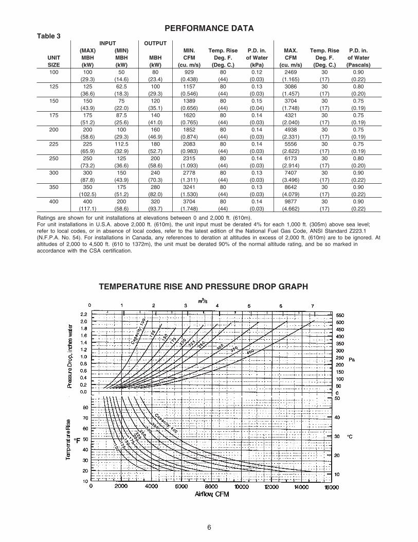
Ratings are shown for unit installations at elevations between 0 and 2,000 ft. (610m).For unit installations in U.S.A. above 2,000 ft. (610m), the unit input must be derated 4% for each 1,000 ft. (305m) above sea level;refer to local codes, or in absence of local codes, refer to the latest edition of the National Fuel Gas Code, ANSI Standard Z223.1(N.F.P.A. No. 54). For installations in Canada, any references to deration at altitudes in excess of 2,000 ft. (610m) are to be ignored. Ataltitudes of 2,000 to 4,500 ft. (610 to 1372m), the unit must be derated 90% of the normal altitude rating, and be so marked inaccordance with the CSA certification.
INPUT OUTPUT(MAX) (MIN) MIN. Temp. Rise P.D. in. MAX. Temp. Rise P.D. in.
UNIT MBH MBH MBH CFM Deg. F. of Water CFM Deg. F. of WaterSIZE (kW) (kW) (kW) (cu. m/s) (Deg. C.) (kPa) (cu. m/s) (Deg. C.) (Pascals)100 100 50 80 929 80 0.12 2469 30 0.90
PUBLIC GARAGES: In repair garages, duct furnacesmust be installed in a detached building or room separatedfrom repair areas as specified in the latest edition of NFPA88B, Repair Garages.
In parking structures, duct furnaces must be installed sothat the burner flames are located a minimum of 18 inches(457mm) above the floor or protected by a partition notless than 18 inches (457mm) high. Refer to the latestedition of NFPA 88A, Parking Structures.
In Canada, installation must be in accordance with thelatest edition of CGA B149 “Installation Codes for GasBurning Appliances and Equipment.”
When the unit is equipped with an automatic gas ignitionsystem, the duct furnace must be installed such that thegas ignition control system is not directly exposed towater spray, rain or dripping water.
Duct furnaces should not be installed to maintainlow temperatures and/or freeze protection ofbuildings. A minimum of 50°F (10°C) thermostatsetting must be maintained. If duct furnaces areoperated to maintain lower than 50°F (10°C), hot fluegases are cooled inside the heat exchanger to the pointwhere water vapor (a flue gas by product) condensesonto the heat exchanger walls. The result is a mildlycorrosive acid that prematurely corrodes the aluminizedheat exchanger and can actually drip water down fromthe duct furnace onto floor surface. Additional ductfurnaces should be installed if a minimum 50°F (10°C)thermostat setting cannot be maintained.
Do not install duct furnaces in corrosiveor flammable atmospheres! Premature failure of, orsevere damage to the unit will result!
Avoid locations where extreme draftscan affect burner operation. Duct furnaces must notbe installed in locations where air for combustionwould contain chlorinated, halogenated or acidicvapors. If located in such an environment, prematurefailure of the unit will occur!
NOTICE: Location of duct furnaces is related directlyto the selection of sizes. Basic rules are as follows:
ACCESSIBILITY: If unit is a bottom service access typeallow a minimum of 21 inches (533mm) at the bottom ofthe unit to facilitate servicing the burners and pilot, or sixinches (152mm) if the unit has a side access burnerdrawer. Provision should also be made to assure acces-sibility for recurrent maintenance purposes.
AIRCRAFT HANGARS: Duct furnaces must be installedin aircraft hangars and public garages as follows: Inaircraft hangars, duct furnaces must be at least 10 feet(3.05m) above the upper surface of wings or engineenclosures of the highest aircraft to be stored in thehangar and 8 feet (2.4m) above the floor in shops,offices and other sections of the hangar where aircraftare not stored or housed. Refer to current ANSI/NFPANo. 409, Aircraft Hangars. In Canada, installation issuitable in aircraft hangars when acceptable to theenforcing authorities.
CLEARANCES
DRAFTS: Avoid installing the duct furnace in anextremely drafty location. Strong drafts may cause pilotoutage. Units with intermittent pilot ignition may bepreferable in areas where drafts cannot be avoided.
Atmospheres containing commercial solvents orchlorinated hydrocarbons will produce corrosive acidswhen coming in contact with the flames. This will greatlyreduce the life of the gas duct furnace and may void thewarranty. Avoid such areas.
NOTICE: If the gas duct furnace is to be used in abuilding classified as having a hazardousatmosphere, the installation must comply with thestandards set by the National Board of FireUnderwriters. Consult the authorities havingjurisdiction before starting the job.
The duct furnace must be installed on the positivepressure side of the air circulation blower.
Under no circumstances shouldcombustible material be located within theclearances specified in Table 4. Failure to provideproper clearance could result in personal injuryor equipment damage from fire.
Maintain adequate clearances around air openings intocombustion chamber:
Table 4 - Minimum Clearances
*21" (533 mm) is required foraccessibility on furnaces withbottom access burnercompartments.
SIDESTOP
BOTTOM*FLUE
6" (152 mm)6" (152 mm)6" (152 mm)6" (152 mm)
*When the clearances requiredfor accessibility are greater thanthe minimum safety clearances,the accessibility clearances takeprecedence.
8
Figure 5 - Recommended Design for FieldInstallation of Ductwork for Straight-Through Arrangement
DUCTWORKProperly designed and installed ductwork, providing auniformly distributed flow of air across the surfaces ofthe heat exchanger, is essential to satisfactory unitperformance and life of the equipment.
All duct connection flanges/seams must be sealed toprevent air leaks. Sealant/tape must be suitable fortemperatures 250°F (121°C) minimum.
Any attempt to straighten the 90°duct connection flanges on the duct furnaces willaffect the operation of the furnace and will voidthe warranty.
If uniform air distribution is not obtained, installadditional baffles and/or turning vanes in the ductwork.
Figures 5 and 6 illustrate recommended ductworkdesigns for both the straight-through and elbowed airinlet arrangements.
Access panels large enough to observe smoke andreflected light, and to detect the presence of leaks inthe heating equipment, are required both upstream anddownstream from gas duct furnaces. These panelsmust be sealed to prevent air leaks. If allowed by localregulations, install canvas connectors between theductwork and fan discharge opening to eliminate thetransmission of mechanical vibration.
AIR FLOWThe installation is to be adjusted to obtain an airthroughput within the range specified on the appliancerating plate.
INSTALLATION
COMBUSTION INLET AIR VENTILATIONInlet Air From Another Room — If the duct furnace isinstalled in a tightly constructed room or compartment,provide two inlet air openings. The size of each ventopening should be no less than one square inch (6.452square centimeters) of free area for each 1000 Btu/hr.(293 W) input. Each opening must not be less than 100square inches (645 square centimeters).
Inlet Air From Outdoors — If the enclosed space is tohave inlet combustion air from the outside, the ventopening must not be smaller than one square inch(6.452 square centimeters) of free area for each 2500-3000 Btu/hr. (733-879 W) input. Each opening must notbe less than 100 square inches (645 squarecentimeters).
BYPASSWhen a gas duct furnace is installed to operate inconjunction with a summer air conditioning system, thecfm air delivery of the system blower should beadjusted to meet the design air volume requirementsfor cooling. If this cfm delivery is greater than thatrequired for heating, resulting in a low air temperaturerise, install a damper bypass around the gas ductfurnace to bypass a portion of the air.
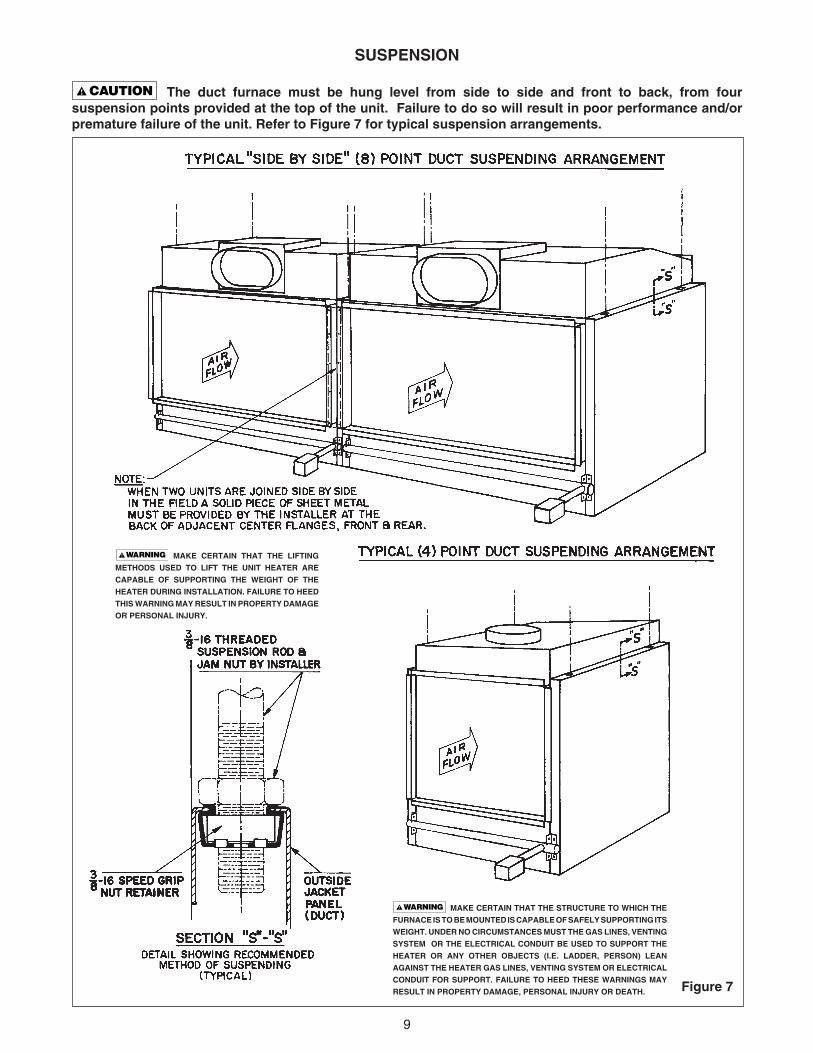
Insure that all hardware used inthe suspension or each unit heater is more thanadequate for the job. Failure to do so mayresult in extensive property damage, personalinjury or death.
9
Figure 7
SUSPENSION
The duct furnace must be hung level from side to side and front to back, from foursuspension points provided at the top of the unit. Failure to do so will result in poor performance and/orpremature failure of the unit. Refer to Figure 7 for typical suspension arrangements.
MAKE CERTAIN THAT THE STRUCTURE TO WHICH THE
FURNACE IS TO BE MOUNTED IS CAPABLE OF SAFELY SUPPORTING ITS
WEIGHT. UNDER NO CIRCUMSTANCES MUST THE GAS LINES, VENTING
SYSTEM OR THE ELECTRICAL CONDUIT BE USED TO SUPPORT THE
HEATER OR ANY OTHER OBJECTS (I.E. LADDER, PERSON) LEAN
AGAINST THE HEATER GAS LINES, VENTING SYSTEM OR ELECTRICAL
CONDUIT FOR SUPPORT. FAILURE TO HEED THESE WARNINGS MAY
RESULT IN PROPERTY DAMAGE, PERSONAL INJURY OR DEATH.
MAKE CERTAIN THAT THE LIFTING
METHODS USED TO LIFT THE UNIT HEATER ARE
CAPABLE OF SUPPORTING THE WEIGHT OF THE
HEATER DURING INSTALLATION. FAILURE TO HEED
THIS WARNING MAY RESULT IN PROPERTY DAMAGE
OR PERSONAL INJURY.
10
ELECTRICAL CONNECTIONS
HAZARDOUS VOLTAGE!DISCONNECT ALL ELECTRICPOWER INCLUDING REMOTEDISCONNECTS BEFORESERVICING. Failure todisconnect power beforeservicing can cause severepersonal injury or death.
Standard units are shipped for use on 115 volt, 60 hertzsingle phase electric power. The motor name-plate andelectrical rating on the transformer should be checkedbefore energizing the duct furnace electrical system. Allexternal wiring must conform to the latest edition of ANSI/NFPA No. 70, National Electrical Code and applicablelocal codes; in Canada, to the Canadian Electrical Code,Part 1 CSA Standard C22.1.
Do not use any tools (i.e. screwdriver,pliers, etc.) across the terminals to check for power.Use a voltmeter.
USE COPPER CONDUCTORS ONLY!UNIT TERMINALS ARE NOT DESIGNED TO ACCEPTOTHER TYPES OF CONDUCTORS. Failure to do somay cause damage to the equipment.
It is recommended that the electrical power supply to eachduct furnace be provided by a separate, fused andpermanently live electrical circuit. A disconnect switch ofsuitable electrical rating for each duct furnace should belocated as close to the gas valve and controls as possible.Each duct furnace must be electrically grounded inaccordance with the latest edition of the National ElectricCode, ANSI/NFPA No. 70 or CSA Standard C22.1.
THERMOSTAT WIRING AND LOCATION
NOTICE: The thermostat must be mounted on avertical vibration-free surface free from air currentsand in accordance with the furnished instructions.
Mount the thermostat approximately 5 feet (1.5 m) abovethe floor in an area where it will be exposed to a freecirculation of average temperature air. Always refer to thethermostat instructions as well as our unit wiring diagramand wire accordingly. Avoid mounting the thermostat inthe following locations:1. Cold areas - Outside walls or areas where drafts may
affect the operation of the control.2. Hot areas - Areas where the sun's rays, radiation, or
warm air currents may affect control operation.3. Dead areas - Areas where air cannot circulate freely,
such as behind doors or in corners.
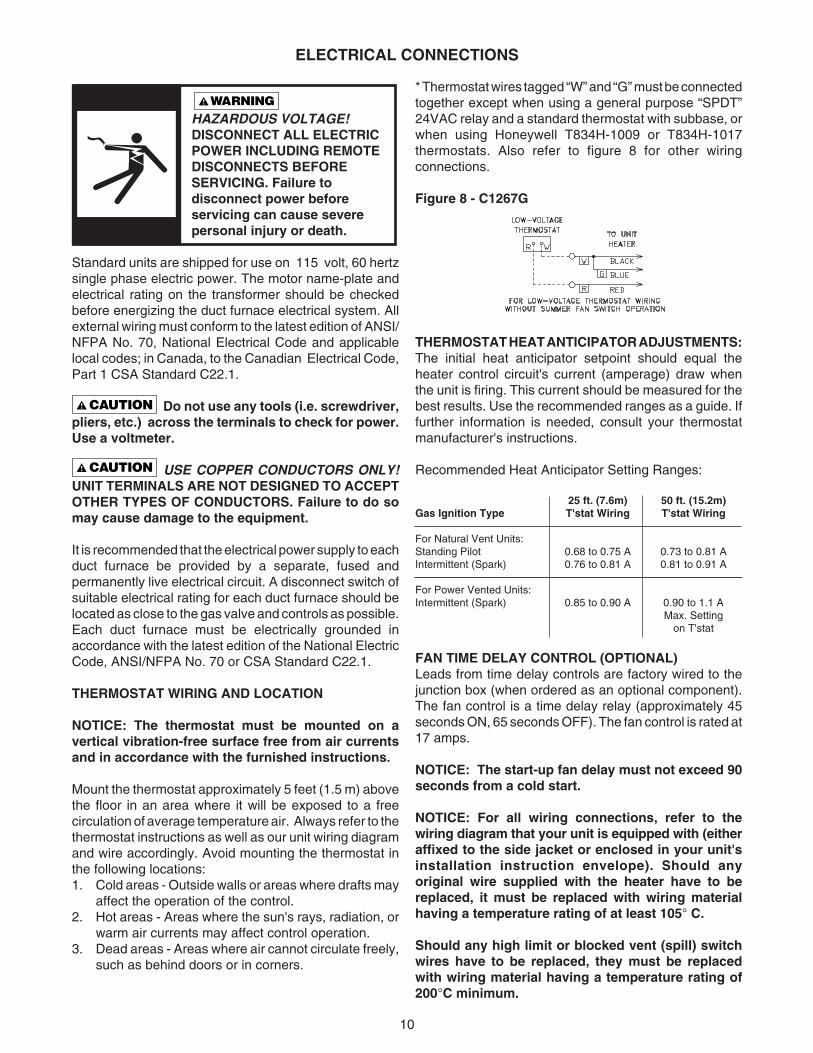
* Thermostat wires tagged “W” and “G” must be connectedtogether except when using a general purpose “SPDT”24VAC relay and a standard thermostat with subbase, orwhen using Honeywell T834H-1009 or T834H-1017thermostats. Also refer to figure 8 for other wiringconnections.
Figure 8 - C1267G
THERMOSTAT HEAT ANTICIPATOR ADJUSTMENTS:The initial heat anticipator setpoint should equal theheater control circuit's current (amperage) draw whenthe unit is firing. This current should be measured for thebest results. Use the recommended ranges as a guide. Iffurther information is needed, consult your thermostatmanufacturer's instructions.
Recommended Heat Anticipator Setting Ranges:
25 ft. (7.6m) 50 ft. (15.2m)Gas Ignition Type T'stat Wiring T'stat Wiring
For Natural Vent Units:Standing Pilot 0.68 to 0.75 A 0.73 to 0.81 AIntermittent (Spark) 0.76 to 0.81 A 0.81 to 0.91 A
For Power Vented Units:Intermittent (Spark) 0.85 to 0.90 A 0.90 to 1.1 A
Max. Settingon T'stat
FAN TIME DELAY CONTROL (OPTIONAL)Leads from time delay controls are factory wired to thejunction box (when ordered as an optional component).The fan control is a time delay relay (approximately 45seconds ON, 65 seconds OFF). The fan control is rated at17 amps.
NOTICE: The start-up fan delay must not exceed 90seconds from a cold start.
NOTICE: For all wiring connections, refer to thewiring diagram that your unit is equipped with (eitheraffixed to the side jacket or enclosed in your unit'sinstallation instruction envelope). Should anyoriginal wire supplied with the heater have to bereplaced, it must be replaced with wiring materialhaving a temperature rating of at least 105° C.
Should any high limit or blocked vent (spill) switchwires have to be replaced, they must be replacedwith wiring material having a temperature rating of200°C minimum.
11
VENTING
ANSI now organizes ventedappliances into four categories.
VENTING FOR NATURAL VENTED (CATEGORY I) DUCT FURNACES(Figures 1 and 2)
ALL DUCT FURNACES MUST BE VENTED!All venting installations shall be in accordance with “Part7 , Venting of Equipment of the National Fuel Gas Code,ANSI Z223.1, or applicable provisions of local buildingcodes.” See below for Canadian Installations. *
CARBON MONOXIDE! Yourventing system must not be blocked by any snow,snow drifts, or any foreign matter. Inspect yourventing system to ensure adequate ventilationexists at all times! Failure to heed these warningscould result in Carbon Monoxide Poisoning(symptoms include grogginess, lethargy,inappropriate tiredness, or flu-like symptoms).
This duct furnace is equipped with ablocked vent (spill) shutoff switch.
Before start up, push reset button on blocked vent(spill) shutoff switch.
If the venting system becomes blocked or there iscontinuous spillage, the vent shutoff switch will shutoff the duct furnace. Before resetting the switch,check to see if the vent system is blocked; removeany blockage.
To reset the switch (which is located in the uppercorner of the draft diverter), push the reset buttonafter the duct furnace has cooled down.
NOTICE: The switch will not reset hot.
Observe the following precautions when venting the unit: 1. Use flue pipe of the same size as the flue
connections on the gas duct furnace (See Table #1).All heaters should be vented with a UL Listed Type Bvent; a factory built chimney or a lined brick andmortar chimney that has been constructed inaccordance with the National Building Code.
2. Where two or more gas duct furnaces vent into acommon flue, the cross sectional area of thecommon flue must be equal to the largest ventconnection, plus 50% of the area of each additionalvent connection.
3. Provide as long a vertical run of flue at the gas ductfurnace as possible. A minimum of five feet (1.52m)of vertical flue is required. The top of the vent pipeshould extend at least two feet (.61 m) above thehighest point on the roof. Install a weather cap overthe vent opening.
4. Slope horizontal runs upward from the gas ductfurnace at least 1/4-inch per foot (21mm/m).Horizontal runs should not exceed 75% of the verticalheight of the vent pipe, or chimney, above the fluepipe connection, up to a maximum length of 10 feet(3m). Horizontal portions of the venting system shallbe supported at maximum intervals of four feet(1.22m) to prevent sagging. See Figure 9.
Category IIncludes non-condensingappliances with negative ventpressure, like the traditionalatmospheric unit heater.
NOTICE: Category II and IV donot apply to equipment specifiedwithin this manual.
Venting CategoriesNon
Condensing CondensingNegativeVent I IIPressurePositiveVent III IVPressure
Figure 9
* The following instructions apply to Canadianinstallations in addition to installation and operatinginstructions:
1. Installation must conform with local building codes,or in absence of local codes, with current CGAB149.1, Installation Codes for Natural Gas BurningAppliances and Equipment, or CGA B149.2,Installation Codes for Propane Gas BurningAppliances and Equipment.
2. Any reference to U.S. standards or codes in theseinstructions are to be ignored and the applicableCanadian standards or codes applied.
12
ALL DUCT FURNACES MUST BE VENTED! All ventinginstallations shall be in accordance with the latest editionof Part 7, venting of Equipment of the National Fuel GasCode, ANSI Z223.1, or applicable provisions of localbuilding codes for natural or power vented units. Also seepage 13 for additional Canadian installations.
Horizontal vent systems must be in compliance withUL 1738 for installations in the United States,and ULS636 for installations in Canada.
Power vented units are designed to be used withsingle wall vent pipe utilizing horizontal or verticalventing arrangements. These arrangements mustterminate external to the building using either asingle wall or double wall (Type B) vent. See Figures10 thru 16 for special installation requirementsregarding these venting conditions.
Do not use a type B (double wall)vent internally within the building on our powervented units!
If double wall venting is used, components which are ULListed and approved for Category III positive pressureventing systems MUST be used.
A Briedart Type L, Field Starkap or an equivalent ventcap must be supplied by the customer for each powervented unit. The vent pipe diameter MUST be asspecified in the chart on page 5 (“D” Dia. Flue Opening).A reducer must be field installed for 100 through175 MBH Unit Sizes. All 300 through 400 MBH Unitsizes are factory equipped with the required flueincreaser. Refer to Figures 11 thru 16 for additionalrequirements.
The venting system for these appliances shallterminate at least four feet (1.2m) below, four feet (1.2m)horizontal from, or one foot (0.3m) above any door,window, or gravity air inlet into any building.
Through the wall vents for these appliances shall NOTterminate over public walkways, or over an area wherecondensate or vapor could create a nuisance or hazardor could be detrimental to the operation of regulators,relief valves, or other equipment.
VENTING FOR POWER VENTED (CATEGORY III) DUCT FURNACES(Figures 3 and 4)
The vent pipe equivalent length must be 5 ft. (1.5m)minimum and must not exceed 50 ft. (15.2m). Equivalentlength is the total length of straight sections PLUS 15 ft.(4.6m) for each 90 degree elbow, 8 ft. (2.4m) for each 45degree elbow, and 10 ft. (3.0m) for the vent cap.
Maintain 6 in. (152mm) between vent pipe andcombustible materials. A minimum of 12 in. (305mm) ofstraight pipe is required from the venter outlet beforeinstalling an elbow in the vent system. An elbowshould never be attached directly to the venter!
Use single wall pipe constructed of 26 gauge galvanizedsteel or material of equivalent durability and corrosionresistance for the vent system. For installation inCanada, use pipe constructed from 0.025 inch thickaluminum or 0.018 inch thick stainless steel.
Never use a pipe of a diameterother than that specified in Tables 1 or 2! Neveruse pvc or other nonmetallic pipe for venting!To do so may result in serious damage to theunit or severe personal injury or death!
Any run of single wall vent pipe passing through anunheated space must be insulated with an insulationsuitable to 550°F.
The vent terminal must be installed with a minimumclearance of four feet (1.2m) from electric meters, gasmeters, regulators and relief equipment.
Seal ALL vent pipe joints and seams to prevent leakage.Use General Electric RTV-108 or Dow-Corning RTV-732silicone sealant; or 3M #425 aluminum foil tape.
The vent system must be installed to prevent collectionof condensate. Vertical vent pipes should be equippedwith condensate drains. Pitch horizontal pipesdownward 1/4 in. per foot (21mm/m) toward outlet forcondensate drainage.
Horizontal portions of the venting system shall besupported at maximum intervals of four feet (1.2m) toprevent sagging (in Canada, support at 3 feet (1m)maximum intervals).
Insulate single wall vent pipe exposed to cold air orrunning through unheated areas.
5. Use as few elbows as possible. 6. Tape flue pipe joints with fireproof paper or material. 7. Avoid running vent pipe through unheated spaces. 8. When this cannot be avoided, insulate the pipe to
prevent the condensation of moisture on the insidewalls of the pipe.
9. Do not damper the flue piping. Failure to open sucha damper prior to operating the gas duct furnacewill result in the spillage of flue gas into theoccupied space, activating blocked vent (spill)switch. See prior instructions.
10. Avoid installing units in areas under negativepressure due to large exhaust fans or airconditioning. When required, a flue vent fan shouldbe installed in accordance with the instructionsincluded with the fan.
11. This optional draftor/power venter is designed tooperate as a Category I venting system – wheninstalled per Installation Instructions to a Category Iunit with a draft diverter.
12. Vent connectors serving Category I heaters shall notbe connected into any portion of mechanical draftsystems operating under positive pressure.
13
Each unit must have an individual vent pipe and ventterminal per furnace section! Each unit MUST NOT beconnected to other vent systems or to a chimney.
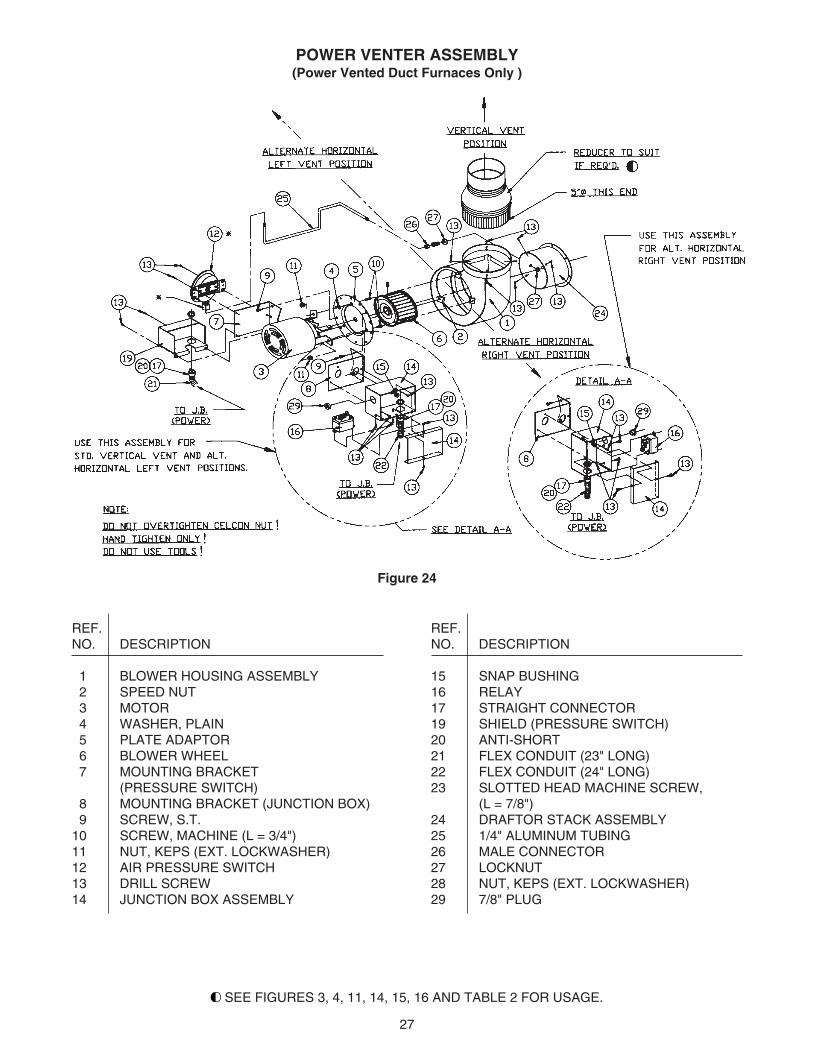
Units are shipped from the factory set up for verticalventing. To convert the power venter for horizontalventing, remove the shipping support bracket; refer toFigures 10 and 24, and follow this procedure:
1. Hold power venter motor in position.2. Remove the three Phillips-head screws from the
motor adaptor plate.3. Remove the three screws which connect the
power venter stack to the power venter housing.4. Rotate the power venter housing to the horizontal
position.5. Replace screws accordingly.
NOTICE: The motor, pressure switch, and junctionbox bracket MUST remain located as shipped fromthe factory. Rotate only the blower housing! If thepower venter housing is to be moved to the righthorizontal position, the junction box must be rotated90 degrees CCW to clear the connection. To do this,remove all wires, conduit and conduit connectorfrom the junction box, noting location of wires. Movebox, using holes provided. Move 7/8" plug frombottom of box to side. Reconnect all wires accordingto the unit’s wiring diagram.
Vent Systems - Termination Clearance Requirements*
Minimum Clearances for
Structure Termination Locations
4 feet below
Door, window or any gravity air inlet 4 feet horizontally
1 foot above
Forced air inlet within 10 ft. 3 feet above
Adjoining building or parapet 6 feet
Adjacent public walkways 7 feet above grade
*If the vent terminal is to be installed near ground level, the vent terminalmust be positioned at least six inches above the maximum anticipatedsnow depth (see below for Canadian requirements)
REFER TO SPECIFICATION TABLE AND INSTALLATION MANUAL FOR PROPER USAGEThe following instructions apply to Canadian installationsin addition to installation and operating instructions:1. Installation must conform with local building codes, or
in absence of local codes, with current CGA B149.1installation codes for natural gas burning appliancesand equipment, or CGA B149.2, installation codes forpropane gas burning appliances and equipment.
2. Any references to U.S. standards or codes in theseinstructions are to be ignored and the applicableCanadian standards or codes applied.
3. If using a metal vent system under positive gaugepressure in Canada, a slip fit vent connection must besecured by at least two corrosion-resistant screws, orother mechanical locking means.
4. The vent shall not terminate -a. Less than 6 feet (1.8m) from a combustion air
inlet or another appliance.b. Less than 3 feet (1m) from any other building
opening or any gas service regulator.c. Directly above a gas utility meter or service
regulator.
* USA units - thereducer must befield supplied for100, 125, 150 and175 MBH unit sizes.
14
Figure 12A
Figure 12B
15
Figure 13A
Figure 13B
16
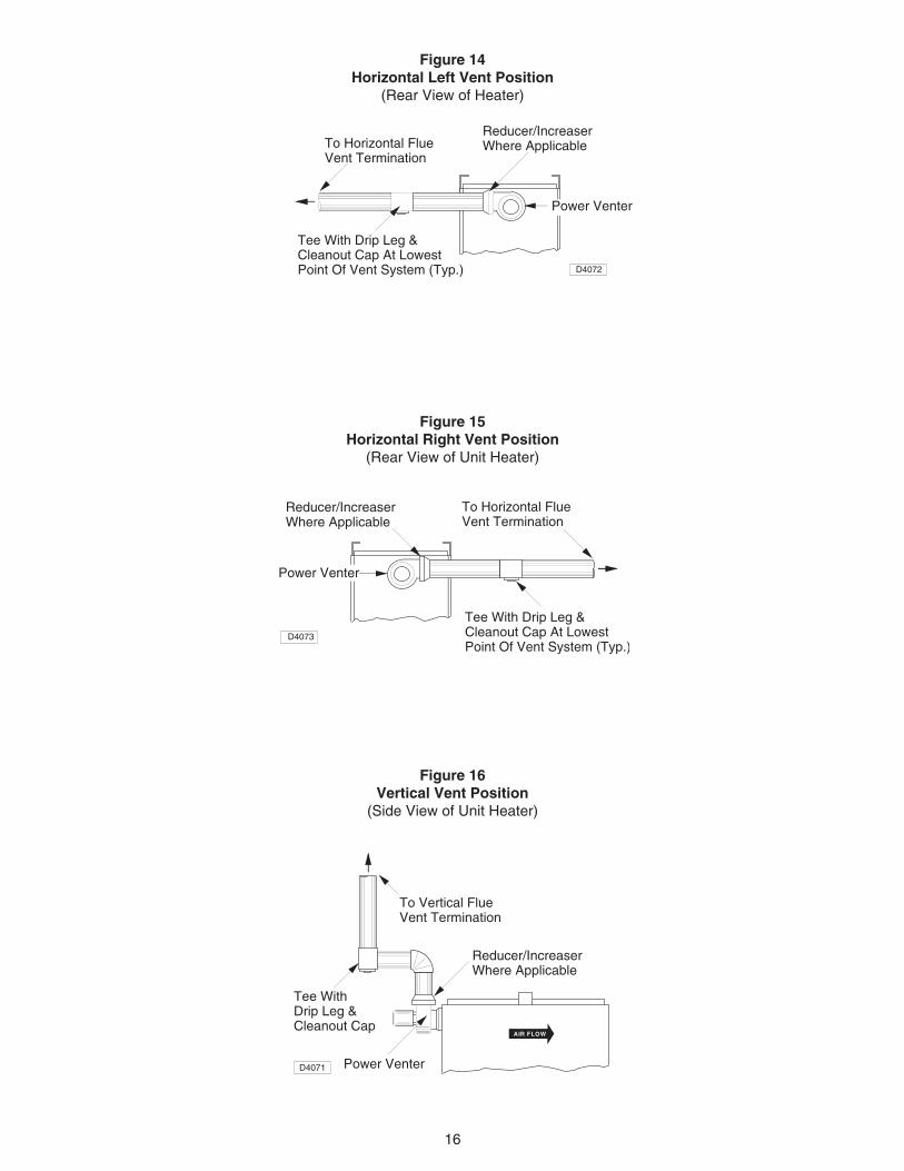
Figure 14Horizontal Left Vent Position
(Rear View of Heater)
Figure 15Horizontal Right Vent Position
(Rear View of Unit Heater)
Figure 16Vertical Vent Position
(Side View of Unit Heater)
������
Tee With Drip Leg &Cleanout Cap At LowestPoint Of Vent System (Typ.) D4072
To Horizontal Flue Vent Termination
Reducer/IncreaserWhere Applicable
Power Venter
����Power Venter
Tee With Drip Leg &Cleanout Cap At LowestPoint Of Vent System (Typ.)
D4073
To Horizontal Flue Vent Termination
��
Reducer/IncreaserWhere Applicable
������
D4071
������
AIR FLOW
Power Venter
Tee WithDrip Leg &Cleanout Cap
To Vertical Flue Vent Termination
Reducer/IncreaserWhere Applicable
17
GAS PIPING
To avoid equipment damage or possible personal injury, do not connect gas piping tothis unit until a supply line pressure/leak test has been completed. Connecting the unit beforecompleting the pressure/leak test may damage the unit gas valve and result in a fire hazard.
Do not rely on a shut off valve to isolate the unit while conducting gas pressure/leak tests. These valvesmay not be completely shut off, exposing the unit gas valve to excessive pressure and damage.
PIPE SIZINGTo provide adequate gas pressure at the gas ductfurnace, size the gas piping as follows:1. Find the cu ft/hr by using the following formula: Input
Cu ft/hr = Btu2. Refer to Table 5. Match “Pipe Run in Feet” with
appropriate “Gas Input - Cu Ft/Hr” figure. Thisfigure can then be matched to the pipe size at theend of the column.
Example: It is determined that a 67 foot (20.4m) run of gaspipe is required to connect a 200 MBTU gas duct furnaceto a 1,000 Btu/cu. ft (0.29 kW) natural gas supply.
200,000 Btu/hr = 200 Cu ft/hr 1,000 Btu/cu ft
Using Table 5, a 1 inch nominal diameter pipe is needed.
NOTICE: See General Safety Information sectionfor english/SI (metric) unit conversion factors.
NominalIron
Pipe SizeInternal
Dia.
Maximum Capacity of Pipe in Cubic Feet of Gas per Hour for Gas Pressures of 0.5 psig (3.5 kPa) or Less,and a Pressure Drop of 0.5 Inch Water Column (124.4 Pa)
(Based on a 0.60 Specific Gravity Gas)
Length of Pipe, ft. (Meters)
GAS PIPE SIZE
in. in. 10 20 30 40 50 60 70 80 90 100 125 150 175 200
1. Determine the required Cu. Ft. / Hr. by dividing the rated heater input by 1000. 2. FOR NATURAL GAS: Select the pipe size directlyfrom the table. 3. FOR PROPANE GAS: Multiply the Cu. Ft. / Hr. value by 0.633; then use the table. 4. Refer to the metric conversionfactors listed in General Safety section for SI unit measurements/conversions.
Table 5
NOTICE: If more than one gas duct furnace is to beserved by the same piping arrangement, the total cuft/hr input and length of pipe must be considered.
NOTICE: If the gas duct furnace is to be fired withLP gas, see below and consult the local LP gasdealer for pipe size information.
NOTICE: HEATER INSTALLATION FOR USE WITHPROPANE (BOTTLED) GAS MUST BE MADE BY AQUALIFIED L.P. GAS DEALER OR INSTALLER. HEWILL INSURE THAT PROPER JOINT COMPOUNDSARE USED FOR MAKING PIPE CONNECTIONS; THATAIR IS PURGED FROM LINES; THAT A THOROUGHTEST IS MADE FOR LEAKS BEFORE OPERATINGHEATER; AND THAT IT IS PROPERLY CONNECTEDTO PROPANE GAS SUPPLY SYSTEM.
Before any connection is made to an existing linesupplying other gas appliances, contact the local gascompany to make certain that the existing line is ofadequate size to handle the combined load.
18
Check all pipe joints for leakageusing a soap solution or other approved method.Never use an open flame or severe personalinjury or death may occur.
Figure 17 - Pipe Installation, Standard controls
Never use an open flame todetect gas leaks. Explosive conditions may existwhich would result in personal injury or death.
The appliance and its individual shutoff valve must bedisconnected from the gas supply piping systemduring any pressure testing of that system at testpressures in excess of 1/2 psig (3.5 kPa).
The appliance must be isolated from the gas supplypiping system by closing its individual manual shutoffvalve during any pressure testing of the gas supplypiping system at test pressures equal to or less than1/2 psig (3.5 kPa).
Table 6 - Gas Piping Requirements
SINGLE STAGE GAS PIPING REQUIREMENTS*
GasType Natural Gas Propane (LP) Gas
Manifold 3.5 in. W.C. 10.0 in. W.C.Pressure (0.9 kPa) (2.5 kPa)
14.0 in. W.C. Max. 14.0 in. W.C. Max.Supply Inlet (3.5 kPa) (3.5 kPa)Pressure 5.0 in. W.C. Min. 11.0 in W.C. Min.
(1.2 kPa) (2.7 kPa)
*For single stage application only at normal altitudes.
TWO STAGE GAS PIPING REQUIREMENTS**
Gas Type Natural Gas Propane (LP) Gas
Supply Inlet 6.5 in. W.C. Min. 11.5 in. W.C. Min.Pressure (1.6 kPa) (2.9 kPa)
**For two stage applications only at normal altitudes.
PIPE INSTALLATION
1. Install the gas piping in accordance withapplicable local codes.
2. Check gas supply pressure. Each duct furnace mustbe connected to a manifold pressure and a gassupply capable of supplying its full rated capacityas specified in Table 6. A field LP tank regulatormust be used to limit the supply pressure tomaximum of 14" W.C. (3.5 kPa). All piping shouldbe sized in accordance with the latest edition ofANSI Standard Z223.1 National Fuel Gas Code; inCanada, according to CGA B149. See Tables 1, 2and 5 for correct gas supply piping size. If gaspressure is excessive on natural gas applications,install a pressure regulating valve in the lineupstream from the main shutoff valve.
3. Adequately support the piping to prevent strain onthe gas manifold and controls.
4. To prevent the mixing of moisture with gas, runthe take-off piping from the top, or side, of themain.
5. Standard gas duct furnaces, optional two-stageunits, and hydraulic modulating units are suppliedwith a combination valve which includes:a. Manual “A” valveb. Manual “B” valvec. Solenoid valved. Pilot safetye. Pressure regulatorPipe directly in to combination valve (see Figure 17).
6. A 1/8" N.P.T. plugged tapping, accessible for testgauge connection, must be installed immediatelyupstream of the gas supply connection to theappliance
7. Provide a drip leg in the gas piping near the gasduct furnace. A ground joint union and a manual gasshutoff valve should be installed ahead of theunit heater controls to permit servicing. Themanual main shutoff valve must be located externalto the jacket. See Figure 17.
8. Make certain that all connections have beenadequately doped and tightened.
Do not over-tighten the inlet gaspiping into the valve. This may cause stresses thatwould crack the valve!
NOTICE: Use pipe joint sealant resistant to theaction of liquefied petroleum gases regardless ofgas conducted.
19
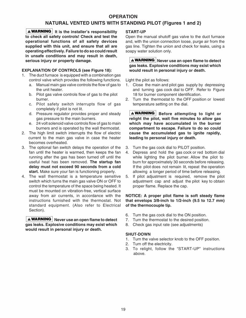
OPERATIONNATURAL VENTED UNITS WITH STANDING PILOT (Figures 1 and 2)
It is the installer’s responsibilityto check all safety controls! Check and test theoperational functions of all safety devicessupplied with this unit, and ensure that all areoperating effectively. Failure to do so could resultin unsafe conditions and may result in death,serious injury or property damage.
EXPLANATION OF CONTROLS (see Figure 18):1. The duct furnace is equipped with a combination gas
control valve which provides the following functions.a. Manual main gas valve controls the flow of gas to
the unit heater.b. Pilot gas valve controls flow of gas to the pilot
burner.c. Pilot safety switch interrupts flow of gas
completely if pilot is not lit.d. Pressure regulator provides proper and steady
gas pressure to the main burners.e. 24 volt solenoid valve controls flow of gas to main
burners and is operated by the wall thermostat.2. The high limit switch interrupts the flow of electric
current to the main gas valve in case the heaterbecomes overheated.
3. The optional fan switch delays the operation of thefan until the heater is warmed, then keeps the fanrunning after the gas has been turned off until theuseful heat has been removed. The startup fandelay must not exceed 90 seconds from a coldstart. Make sure your fan is functioning properly.
4. The wall thermostat is a temperature sensitiveswitch which turns the main gas valve ON or OFF tocontrol the temperature of the space being heated. Itmust be mounted on vibration-free, vertical surfaceaway from air currents, in accordance with theinstructions furnished with the thermostat. Notstandard equipment. (Also refer to ElectricalSection).
Never use an open flame to detectgas leaks. Explosive conditions may exist whichwould result in personal injury or death.
START-UPOpen the manual shutoff gas valve to the duct furnaceand, with the union connection loose, purge air from thegas line. Tighten the union and check for leaks, using asoapy water solution only.
Never use an open flame to detectgas leaks. Explosive conditions may exist whichwould result in personal injury or death.
Light the pilot as follows:1. Close the main and pilot gas supply by depressing
and turning gas cock dial to OFF. Refer to Figure18 for burner component identification.
2. Turn the thermostat to the OFF position or lowesttemperature setting on the dial.
Before attempting to light orrelight the pilot, wait five minutes to allow gaswhich may have accumulated in the burnercompartment to escape. Failure to do so couldcause the accumulated gas to ignite rapidly,leading to personal injury or death.
3. Turn the gas cock dial to PILOT position.4. Depress and hold the gas cock or red bottom dial
while lighting the pilot burner. Allow the pilot toburn for approximately 30 seconds before releasing.If the pilot does not remain lit, repeat the operationallowing a longer period of time before releasing.
5. If pilot adjustment is required, remove the pilotadjustment cap and adjust the pilot key to obtainproper flame. Replace the cap.
NOTICE: A proper pilot flame is soft steady flamethat envelops 3/8-inch to 1/2-inch (9.5 to 12.7 mm)of the thermocouple tip.
6. Turn the gas cock dial to the ON position.7. Turn the thermostat to the desired position.8. Check gas input rate (see adjustments)
SHUT-DOWN1. Turn the valve selector knob to the OFF position.2. Turn off the electricity.3. To relight, follow the “START-UP” instructions
above.
20
ON
8C9
Figure 18 - Burner Components — Standing Pilot ComponentsAlso refer to Figures 1, 2 and 21 thru 25 for component locations.
BURNER DRAWER - COMMON PARTS:1.) Main Burners2.) Burner Manifold3.) Air Shutters4.) Burner Springs
CONTROLS:8A.) Honeywell VR8200
Gas Valve8B.) Honeywell VR8300
Gas Valve8C.) White-Rodgers 36C
Gas Valve
Standing Pilot Parts/Controls
5.) Main Burner Orifice6.) Transformer/Junction Box7.) Pilot Tubing
9.)* High Limit Switch10.) Pilot Burner Assembly11.)† Blocked Vent (Spill) Switch
*These safety devices are located on the rear header plate ofheat exchanger (inlet air side).†This safety device is located in the upper right corner of the rightside of your unit.
Bottom access manifold shown.
7
10
D4298A
8A
Honeywell Standing Pilot Gas ValveVR8200
Standing Pilot Burner Assembly
Transformer
8B
D3684A
6
High LimitWhite Rodgers Standing Pilot Gas Valve36C
(Used with Johnson-Control Solenoid Valve)
Honeywell Standing Pilot Gas ValveVR8300
11
Blocked Vent (Spill) Switch
������
13
54
1
2
◗
◗
21
OPERATIONUNITS WITH INTERMITTENT PILOT IGNITION
Optional for Natural Vented (Standard) Duct Furnaces (Figures 1 and 2)
It is the installer’s responsibilityto check all safety controls! Check and test theoperational functions of all safety devicessupplied with this unit, and ensure that all areoperating effectively. Failure to do so could resultin unsafe conditions and may result in death,serious injury or property damage.
EXPLANATION OF CONTROLS (see Figure 19):1. The duct furnace is equipped with a dual automatic
gas valve and electric ignition device (separate fromthe gas valve on some models) which provide thefollowing functions:a. Pilot solenoid valve is energized and pilot is
electrically ignited when thermostat calls for heat.b. Electronic circuitry proves that pilot flame is
established, then energizes main gas solenoidvalve.
c. When thermostat is satisfied, main gas solenoidvalve and pilot solenoid valve are de-energized,stopping all flow of gas.
d. Pilot solenoid valve also functions as a main gasvalve to provide redundancy.
e. Pressure regulator provides proper and steadygas pressure to the main burners.
f. Manual shutoff valve for service and long termshut-down. (Separate from the automatic valveon some models.)
2. The high limit switch interrupts the flow of electriccurrent to the main gas valve in case the heaterbecomes overheated.
3. The optional fan switch delays the operation of the fanuntil the heater is warmed, then keeps the fan runningafter the gas has been turned off until the useful heathas been removed. The start-up fan delay must notexceed 90 seconds from a cold start. Make sureyour fan is functioning properly.
4. The wall thermostat is a temperature sensitive switchwhich turns the main gas valve ON or OFF to controlthe temperature of the space being heated. It must bemounted on a vibration free, vertical surface awayfrom air currents, in accordance with the instructionsfurnished with the thermostat (also refer to ElectricalSection).
START-UP1. Open the manual valve supplying gas to the duct
furnace, and with the union connection loose,purge air from the gas line. Tighten the union andcheck for gas leaks, using a soapy water solutiononly.
Never use an open flame to detectgas leaks. Explosive conditions may exist whichwould result in personal injury or death.
Before attempting to light orrelight pilot, wait 5 minutes to allow gas whichmay have accumulated in the burnercompartment to escape. Failure to do so couldcause the accumulated gas to ignite rapidly,leading to personal injury or death.
2. Open the manual valve on the unit heater.3. Turn on electrical power.4. The unit should be under the control of the
thermostat. Turn the thermostat to the highest pointand determine that the pilot and main burnersignite. Turn the thermostat to the lowest point anddetermine that the pilot and main burners areextinguished.
5. If pilot adjustment is required, remove the pilotadjustment seal cap and adjust the pilot screw toobtain proper flame. Clockwise rotation decreasespilot flame size. Replace the cap.
6. Turn the thermostat to the desired position.7. Refer to “Adjustments” sections for more
specifications.
SHUT DOWN1. Turn the valve selector knob to the “OFF” position.2. Turn off the electricity.3. To relight, follow the “start-up” instructions.
See Figure 19 for parts/identification.
22
OPERATIONPOWER VENTED DUCT FURNACES WITH INTERMITTENT (SPARK) PILOT IGNITION
Mandatory Ignition for Power Vented Duct Furnaces (Figures 3 and 4)
It is the installer’s responsibilityto check all safety controls! Check and test theoperational functions of all safety devicessupplied with this unit, and ensure that all areoperating effectively. Failure to do so couldresult in unsafe conditions and may result indeath, serious injury or property damage.
EXPLANATION OF CONTROLS:1. The duct furnace is equipped with a dual automatic
gas valve and electric ignition device (separate fromthe gas valve on most models) which provide thefollowing functions:a. The duct furnace is equipped with a power vent
system consisting of a power venter motor andblower, pressure switch, and sealed fluecollector in place of the conventional draftdiverter.
Never operate the unit beyond thespecified limits, severe damage to, and/or prematurefailure of the unit will result!
b. The power venter motor is energized by theroom thermostat on a call for heat. The pressureswitch measures the flow through the ventsystem and energizes the indirect spark ignitionsystem when the flow is correct.
The pressure switch MUST NOTbe bypassed. The unit MUST NOT be firedunless the power venter is operating. An unsafecondition could result.
The addition of external draft hoodsor power venters is not permitted. Addition of suchdevices may cause serious unit malfunction orfailure or possible personal injury.
c. The indirect spark ignition system consists ofan ignition control module, a dual combinationgas valve, and a spark-ignited pilot burner.When the pressure switch closes, the pilotvalve opens and a spark is generated to lightthe pilot burner. When the flame sensing circuitsenses that pilot flame is established, the maingas valve is opened to supply gas to the mainburners. When the thermostat is satisfied, thevent system is de-energized and both valvesare closed to stop all flow of gas to the unit.
d. Pilot solenoid valve also functions as a maingas valve to provide redundancy.
e. Pressure regulator provides proper and steadygas pressure to the main burners.
f. Manual shutoff valve for service and long termshut-down. (Separate from the automatic valveon some models.)
2. The high limit switch interrupts the flow of electriccurrent to the main gas valve in case the heaterbecomes overheated.
3. The fan switch delays the operation of the fan untilthe heater is warmed, then keeps the fan runningafter the gas has been turned off until the useful heathas been removed. The start-up fan delay mustnot exceed 90 seconds from a cold start.
4. The wall thermostat (supplied optionally) is atemperature sensitive switch which operates thevent system and ignition system; it turns the maingas valve ON or OFF to control the temperature ofthe space being heated. It must be mounted on avibration free, vertical surface away from aircurrents, in accordance with the instructionsfurnished with the thermostat (also refer to ElectricalSection).
START-UP1. Open the manual valve supplying gas to the unit
heater, and with the union connection loose, purgeair from the gas line. Tighten the union and checkfor gas leaks, using a soapy water solution only.
Never use an open flame to detectgas leaks. Explosive conditions may exist whichwould result in personal injury or death.
Before attempting to light orrelight pilot, wait 5 minutes to allow gas whichmay have accumulated in the burner compart-ment to escape. Failure to do so could causethe accumulated gas to ignite rapidly, leadingto personal injury or death.
2. Open the manual valve on the unit heater.3. Turn ON electrical power.4. The unit should be under the control of the
thermostat. Turn the thermostat to the highest pointand determine that the power venter motor startsand the pilot and main burners ignite. Turn thethermostat to the lowest point and determine thatthe power venter motor shuts off and pilot and mainburners are extinguished.
5. If pilot adjustment is required, remove the pilotadjustment seal cap and adjust the pilot screw toobtain proper flame. Clockwise rotation decreasespilot flame size. Replace the cap.
6. Turn the thermostat to the desired position.7. Refer to “Adjustments” section for more specifi-
cations.
SHUT DOWN1. Turn the valve selector knob to the “OFF” position.2. Turn off the electricity.3. To relight, follow the “start-up” instructions.
See Figure 19 for parts/identification.
23
Burner Drawer Common Parts: 1. Main Burners 2. Burner Manifold 3. Air Shutters 4. Burner Springs 5. Main Burner Orifice 6. Transformer 7. Pilot Tubing
Controls: 8A. Main Gas Valve (Honeywell) 8B. Main Gas Valve (White Rodgers) 9. Honeywell Ignitor10. Honeywell Pilot Burner11. HoneywellL Pilot Orifice13. High Limit
(Located on the Rear Header Plate of theHeat Exchanger - Air Inlet Side)
14. Blocked Vent (Spill) Switch(Located in the Upper Right Corner of theUnit Access Side)
Figure 19 - Burner Components — IntermIttent Pilot IgnitionAlso refer to Figures 1 thru 4 and 21 thru 25 for component locations.
1
2
�
OF
F
8A
��ON
8B
*NOTE: Manifold shown for ductfurnaces with bottom serviceaccess (Figures 1 and 3.)
*
10
11
7
�
������������������������
SP
AR
K
1
M V
2
MV
/PV
3 4
GN
D(B
UR
NE
R)
P V
56
7
8
9
24V
(GN
D)
24V
TH
-W(O
PT
.)
HoneywellWARNING
S8600MCONTINUOUS RE-TRY100% SHUTOFF IP
90 SEC. TRIAL FOR IGNITION
��9
������
13
54
�
6
13
14
C
10
24
TABLE 7 - MAIN BURNER ORIFICE SCHEDULE*
PRIMARY AIR SHUTTER ADJUSTMENTAfter the unit has been operating for at least 15 minutes,adjust the primary air flow to the burners. Turn thefriction-locked, manually-rotated air shutters clockwiseto close, or counterclockwise to open.
For correct air adjustment, close the air shutter until yellowtips in the flame appear. Then open the air shutter to thepoint just beyond the position where yellow tippingdisappears. Refer to Figure 20.
NOTICE: There may be momentary and spasmodicorange flashes in the flame. This is caused by theburning of airborne dust particles, and not to beconfused with the yellow tipping, which is a stable orpermanent situation when there is insufficientprimary air.
Figure 20 - Main Burner Flames
GAS INPUT RATE
Never overfire the duct furnace, asthis may cause unsatisfactory operation or shortenthe life of the heater.
Check the gas input rate as follows (Refer to generalsafety section for metric conversions/SI units):1. Turn off all gas appliances that use gas through the
same meter as the heater.2. Turn gas on to the heater.3. Clock the time in seconds required to burn one cubic
foot of gas by checking the gas meter.4. Insert the time required to burn one cubic foot of
gas into the following formula and compute theinput rate.
3600 (Sec. Per Hr.) x Btu/Cu. Ft = Input Rate Time (Sec.)
For example, assume the Btu content of one cubic foot ofgas equalled 1000 and that it takes 18 seconds to burnone cubic foot of gas.
3600 x 1000 = 200,000 18
NOTICE: If the computation exceeds or is less than95 percent of the gas Btu/hr. input rating (see“Specifications”), adjust the gas pressure.
Adjust the gas pressure as follows:1. NATURAL GAS: Best results are obtained when the
heater is operating at its full input rating with themanifold pressure of 3.5 inches W.C. (0.9 kPa).Adjustment of the pressure regulator is not normallynecessary since it is preset at the factory.
However, field adjustment may be made as follows:a. Attach manometer at pressure tap plug
adjacent to control outlet.b. Remove regulator adjustment screw cap,
located on combination gas valve.c. With a small screwdriver, rotate the adjustment
screw counterclockwise to decrease or clock-wise to increase pressure. Do not force beyondstop limits.
d. Replace regulator adjustment screw cap.2. PROPANE GAS: An exact manifold pressure of
10.0 inches WC (2.5 kPa) must be maintained forproper operation of the heater. If the unit is equippedwith a pressure regulator on the combination gasvalve, follow steps “a” through “d” above. If the unitis not so equipped, the propane gas supply systempressure must be regulated to attain this manifoldoperating pressure.
FT 3/HRORIFICE DRILL
FT 3/HRORIFICE DRILL
FT 3/HRORIFICE DRILL
*INPUT
IN
1000
BTU
NO. OF
BURNER
ORIFICES
3.5" W.C.(0.9 kPa)
10.0" W.C.(2.5 kPa)
MANIFOLDPRESSURE
PROPANETYPE OF GAS NATURAL
2500 BTU/Ft3
(93.1 MJ/m3)
1075 BTU/Ft3
(40.1 MJ/m3)HEATING
VALUE
100
125
150
175
200
225
250
300
350
400
4
5
6
7
8
9
10
12
14
16
9642
12042
14042
16342
18642
21042
23342
28042
32642
37242
405450546054705480549054
10054
12054
14054
16054
FT 3/HRORIFICE DRILL
FT 3/HRORIFICE DRILL
FT 3/HRORIFICE DRILL
FT 3/HRORIFICE DRILL
FT 3/HRORIFICE DRILL
FT 3/HRORIFICE DRILL
FT 3/HRORIFICE DRILL
* This schedule is for units operating at normal altitudes of 2000 ft. (610m) orless. SPECIAL ORIFICES ARE REQUIRED FOR INSTALLATIONS ABOVE2000 FEET (610M).
When installed in Canada, any references to deration at altitudes in excess of2000 feet (610m) are to be ignored. At altitudes of 2000 to 4500 feet (610 to1372m), the unit heaters must be orificed to 90% of the normal altitude rating,and be so marked in accordance with the CSA certification.
LIFTING(TOO MUCH AIR)
YELLOW TIPPING(MARGINAL)
NORMAL(HARD FLAME)
YELLOW FLAME(TOO LITTLE AIR)
25
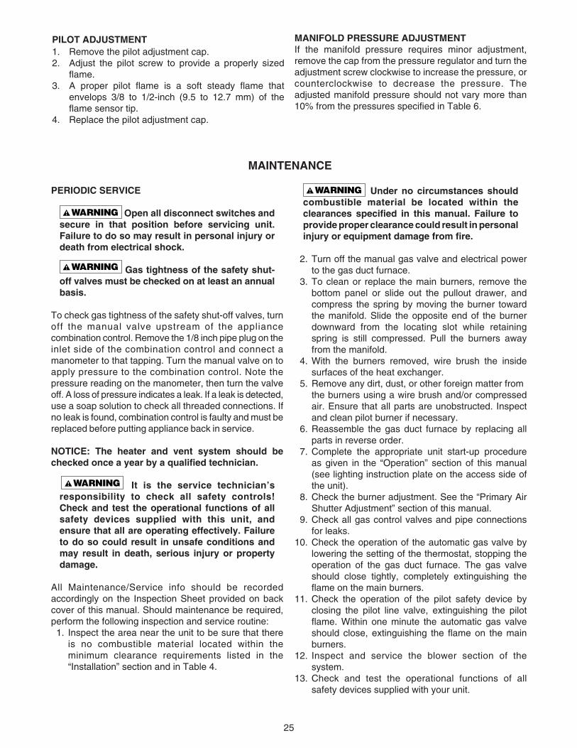
PILOT ADJUSTMENT1. Remove the pilot adjustment cap.2. Adjust the pilot screw to provide a properly sized
flame.3. A proper pilot flame is a soft steady flame that
envelops 3/8 to 1/2-inch (9.5 to 12.7 mm) of theflame sensor tip.
4. Replace the pilot adjustment cap.
MANIFOLD PRESSURE ADJUSTMENTIf the manifold pressure requires minor adjustment,remove the cap from the pressure regulator and turn theadjustment screw clockwise to increase the pressure, orcounterclockwise to decrease the pressure. Theadjusted manifold pressure should not vary more than10% from the pressures specified in Table 6.
Under no circumstances shouldcombustible material be located within theclearances specified in this manual. Failure toprovide proper clearance could result in personalinjury or equipment damage from fire.
2. Turn off the manual gas valve and electrical powerto the gas duct furnace.
3. To clean or replace the main burners, remove thebottom panel or slide out the pullout drawer, andcompress the spring by moving the burner towardthe manifold. Slide the opposite end of the burnerdownward from the locating slot while retainingspring is still compressed. Pull the burners awayfrom the manifold.
4. With the burners removed, wire brush the insidesurfaces of the heat exchanger.
5. Remove any dirt, dust, or other foreign matter fromthe burners using a wire brush and/or compressedair. Ensure that all parts are unobstructed. Inspectand clean pilot burner if necessary.
6. Reassemble the gas duct furnace by replacing allparts in reverse order.
7. Complete the appropriate unit start-up procedureas given in the “Operation” section of this manual(see lighting instruction plate on the access side ofthe unit).
8. Check the burner adjustment. See the “Primary AirShutter Adjustment” section of this manual.
9. Check all gas control valves and pipe connectionsfor leaks.
10. Check the operation of the automatic gas valve bylowering the setting of the thermostat, stopping theoperation of the gas duct furnace. The gas valveshould close tightly, completely extinguishing theflame on the main burners.
11. Check the operation of the pilot safety device byclosing the pilot line valve, extinguishing the pilotflame. Within one minute the automatic gas valveshould close, extinguishing the flame on the mainburners.
12. Inspect and service the blower section of thesystem.
13. Check and test the operational functions of allsafety devices supplied with your unit.
PERIODIC SERVICE
Open all disconnect switches andsecure in that position before servicing unit.Failure to do so may result in personal injury ordeath from electrical shock.
Gas tightness of the safety shut-off valves must be checked on at least an annualbasis.
To check gas tightness of the safety shut-off valves, turnoff the manual valve upstream of the appliancecombination control. Remove the 1/8 inch pipe plug on theinlet side of the combination control and connect amanometer to that tapping. Turn the manual valve on toapply pressure to the combination control. Note thepressure reading on the manometer, then turn the valveoff. A loss of pressure indicates a leak. If a leak is detected,use a soap solution to check all threaded connections. Ifno leak is found, combination control is faulty and must bereplaced before putting appliance back in service.
NOTICE: The heater and vent system should bechecked once a year by a qualified technician.
It is the service technician’sresponsibility to check all safety controls!Check and test the operational functions of allsafety devices supplied with this unit, andensure that all are operating effectively. Failureto do so could result in unsafe conditions andmay result in death, serious injury or propertydamage.
All Maintenance/Service info should be recordedaccordingly on the Inspection Sheet provided on backcover of this manual. Should maintenance be required,perform the following inspection and service routine: 1. Inspect the area near the unit to be sure that there
is no combustible material located within theminimum clearance requirements listed in the“Installation” section and in Table 4.
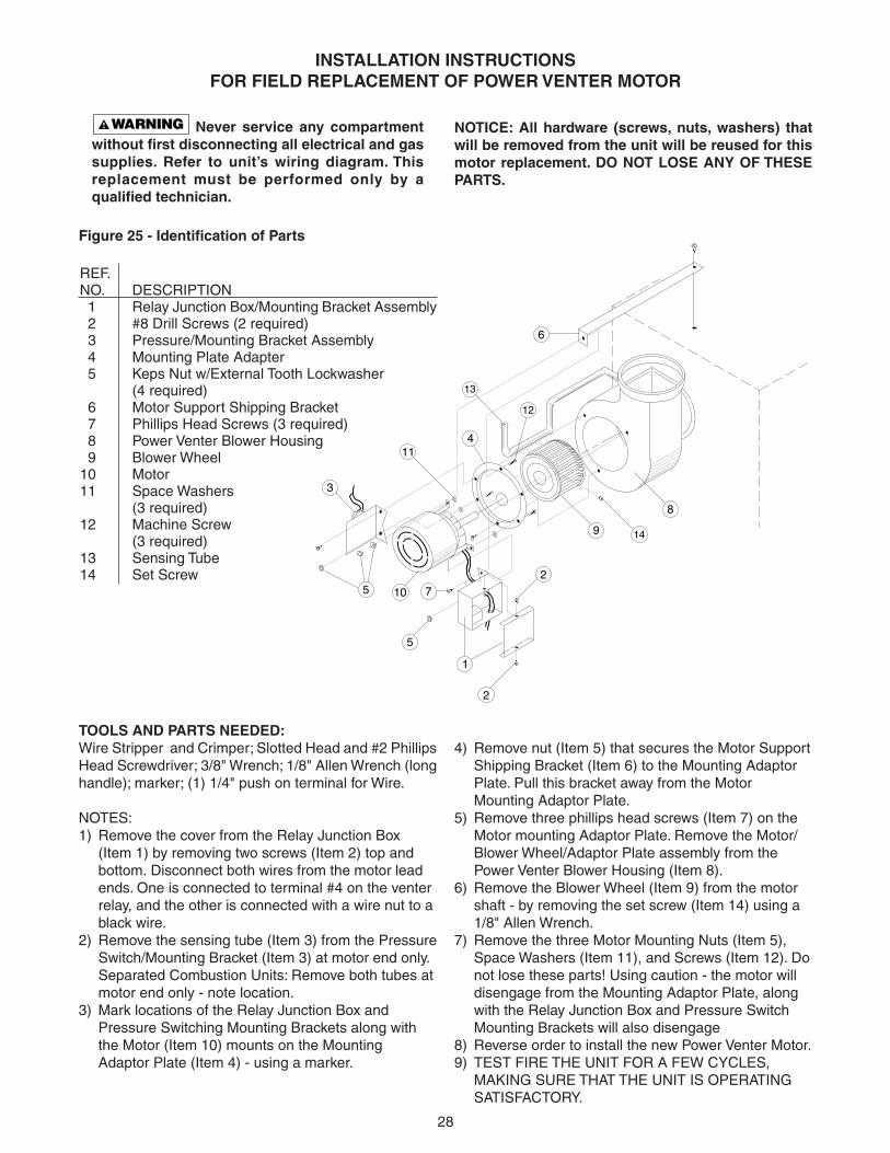
INSTALLATION INSTRUCTIONSFOR FIELD REPLACEMENT OF POWER VENTER MOTOR
TOOLS AND PARTS NEEDED:Wire Stripper and Crimper; Slotted Head and #2 PhillipsHead Screwdriver; 3/8" Wrench; 1/8" Allen Wrench (longhandle); marker; (1) 1/4" push on terminal for Wire.
NOTES:1) Remove the cover from the Relay Junction Box
(Item 1) by removing two screws (Item 2) top andbottom. Disconnect both wires from the motor leadends. One is connected to terminal #4 on the venterrelay, and the other is connected with a wire nut to ablack wire.
2) Remove the sensing tube (Item 3) from the PressureSwitch/Mounting Bracket (Item 3) at motor end only.Separated Combustion Units: Remove both tubes atmotor end only - note location.
3) Mark locations of the Relay Junction Box andPressure Switching Mounting Brackets along withthe Motor (Item 10) mounts on the MountingAdaptor Plate (Item 4) - using a marker.
4) Remove nut (Item 5) that secures the Motor SupportShipping Bracket (Item 6) to the Mounting AdaptorPlate. Pull this bracket away from the MotorMounting Adaptor Plate.
5) Remove three phillips head screws (Item 7) on theMotor mounting Adaptor Plate. Remove the Motor/Blower Wheel/Adaptor Plate assembly from thePower Venter Blower Housing (Item 8).
6) Remove the Blower Wheel (Item 9) from the motorshaft - by removing the set screw (Item 14) using a1/8" Allen Wrench.
7) Remove the three Motor Mounting Nuts (Item 5),Space Washers (Item 11), and Screws (Item 12). Donot lose these parts! Using caution - the motor willdisengage from the Mounting Adaptor Plate, alongwith the Relay Junction Box and Pressure SwitchMounting Brackets will also disengage
8) Reverse order to install the new Power Venter Motor.9) TEST FIRE THE UNIT FOR A FEW CYCLES,
MAKING SURE THAT THE UNIT IS OPERATINGSATISFACTORY.
Never service any compartmentwithout first disconnecting all electrical and gassupplies. Refer to unit’s wiring diagram. Thisreplacement must be performed only by aqualified technician.
NOTICE: All hardware (screws, nuts, washers) thatwill be removed from the unit will be reused for thismotor replacement. DO NOT LOSE ANY OF THESEPARTS.
(4 required) 6 Motor Support Shipping Bracket 7 Phillips Head Screws (3 required) 8 Power Venter Blower Housing 9 Blower Wheel10 Motor11 Space Washers
(3 required)12 Machine Screw
(3 required)13 Sensing Tube14 Set Screw
29
Troubleshooting GuideSYMPTOMS POSSIBLE CAUSE(S) CORRECTIVE ACTION
Table 8
1. Reset manifold pressure. Refer to"Operation".
2. Replace regulator section of combin-ation gas valve or complete valve.
3. Check with local gas supplier forproper orifice size and replace. Referto "Operation".
1. Close air shutter. Refer to "Operation".2. Check with local gas supplier for
proper orifice size and replace. Referto "Operation".
1. Close air shutter.2. Reduce pilot gas. Refer to "Operation".3. Replace orifice.
4. Reset manifold pressure. Refer to"Operation"; Replace regulator sectionof combination gas valve or completevalve; or Check with local gas supplierfor proper orifice size and replace.Refer to "Operation".
1. Open air shutters. Refer to "Oper-ation".
2. Clean main burner ports.3. Replace manifold assembly.4. Clean draft hood.5. Check for dust or lint at air mixer
opening and around the air shutter.6. Clean combustion air inlet openings in
bottom panel, see "Installation".1. Clean flue. Refer to "Installation".2. Clean combustion air inlet openings in
bottom panel, see "Installation".3. Clean heat exchanger.4. Determine cause and repair
accordingly.1. Inspect all gas piping and repair.2. Clean heat exchanger/flue.3. Eliminate drafts. Refer to "Installation".4. See "Installation".5. Clean draft hood.1. Close air shutter. Refer to "Operation".2. Clean main burner ports.3. Reset manifold pressure. Refer to
"Operation".4. Supply piping is inadequately sized.
Refer to "Installation".5. Clean pilot orifice. Refer to "Oper-
ation".6. Eliminate drafts. Refer to "Installation".7. Refer to "Installation".1. Open all manual gas valves.2. Replace fuse or turn on power supply.3. Turn up thermostat4. Check limit switch with continuity
tester. If open, replace limit switch.5. Check wiring per diagrams.
1. Pressure regulator set too high.
2. Defective Regulator.
3. Burner orifice too large.
1. Excessive primary air.2. Burner orifice too small.
1. Too much primary air.2. Noisy pilot3. Irregular orifice causing whistle or
resonance.4. Excessive gas input.
1. Insufficient primary air.
2. Clogged main burner ports.3. Misaligned orifices.4. Clogged draft hood.5. Air shutter linted.
6. Insufficient combustion air.
1. Blocked venting.2. Insufficient combustion air.
3. Blocked heat exchanger.4. Air leak into combustion chamber or
draft hood.1. Shut off gas supply immediately!2. Blocked heat exchanger/venting.3. Drafts around heater.4. Negative Pressure in building.5. Blocked draft hood.1. Excessive primary air.2. Main burner ports clogged near pilot.3. Pressure regulator set too low.
4. Pilot decreases in size when mainburners come on.
5. Pilot flame too small.
6. Drafts around heater.7. Improper venting.1. Main gas off.2. Lack of power at unit.3. Thermostat not calling for heat.4. Defective limit switch.
5. Improper thermostat or transformerwiring at gas valve.
A. Flame lifting from burnerports.
B. Flame pops back.
C. Noisy flame.
D. Yellow tip flame (some yellowtipping on propane gas ispermissible).
E. Floating flame.
F. Gas Odor.
G. Delayed ignition.
H. Failure to ignite.
30
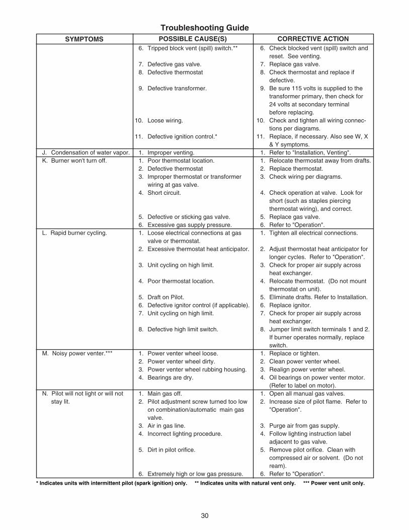
Troubleshooting GuideSYMPTOMS POSSIBLE CAUSE(S) CORRECTIVE ACTION
6. Check blocked vent (spill) switch andreset. See venting.
7. Replace gas valve.8. Check thermostat and replace if
defective.9. Be sure 115 volts is supplied to the
transformer primary, then check for24 volts at secondary terminalbefore replacing.
10. Check and tighten all wiring connec-tions per diagrams.
11. Replace, if necessary. Also see W, X& Y symptoms.
1. Refer to "Installation, Venting".1. Relocate thermostat away from drafts.2. Replace thermostat.3. Check wiring per diagrams.
4. Check operation at valve. Look forshort (such as staples piercingthermostat wiring), and correct.
5. Replace gas valve.6. Refer to "Operation".1. Tighten all electrical connections.
2. Adjust thermostat heat anticipator forlonger cycles. Refer to "Operation".
3. Check for proper air supply acrossheat exchanger.
4. Relocate thermostat. (Do not mountthermostat on unit).
5. Eliminate drafts. Refer to Installation.6. Replace ignitor.7. Check for proper air supply across
heat exchanger.8. Jumper limit switch terminals 1 and 2.
If burner operates normally, replaceswitch.
1. Replace or tighten.2. Clean power venter wheel.3. Realign power venter wheel.4. Oil bearings on power venter motor.
(Refer to label on motor).1. Open all manual gas valves.2. Increase size of pilot flame. Refer to
"Operation".
3. Purge air from gas supply.4. Follow lighting instruction label
adjacent to gas valve.5. Remove pilot orifice. Clean with
5. Defective or sticking gas valve.6. Excessive gas supply pressure.1. Loose electrical connections at gas
valve or thermostat.2. Excessive thermostat heat anticipator.
3. Unit cycling on high limit.
4. Poor thermostat location.
5. Draft on Pilot.6. Defective ignitor control (if applicable).7. Unit cycling on high limit.
8. Defective high limit switch.
1. Power venter wheel loose.2. Power venter wheel dirty.3. Power venter wheel rubbing housing.4. Bearings are dry.
1. Main gas off.2. Pilot adjustment screw turned too low
on combination/automatic main gasvalve.
3. Air in gas line.4. Incorrect lighting procedure.
5. Dirt in pilot orifice.
6. Extremely high or low gas pressure.
J. Condensation of water vapor.K. Burner won't turn off.
L. Rapid burner cycling.
M. Noisy power venter.***
N. Pilot will not light or will notstay lit.
* Indicates units with intermittent pilot (spark ignition) only. ** Indicates units with natural vent only. *** Power vent unit only.
31
7. Defective thermocouple(Standing pilot units only).
8. Drafts around unit.
9. Pilot valve not opening (faultywiring).*
10. No spark (if applicable) (faultywiring).
11. Defective gas valve.1. Loose wiring.
2. Defective motor overload protector ordefective motor.
3. Defective power venter relay.
1. Fan relay heater element improperlywired.
2. Defective venter relay switch.3. Motor overload protector cycling on
and off.
4. Motor not properly oiled.1. Improperly wired venter relay.2. Main burners not lighting while ther-
mostat calls for heat.3. Defective venter relay.1. Incorrect gas input.2. Heater undersized.
3. Thermostat malfunction.4. Heater cycling on limit control.
5. Check outside dampers if used.
7. Check thermocouple connection,and replace if defective.
8. Eliminate drafts. Refer to "Installa-tion".
9. Inspect and correct all wiring.
10. Inspect and correct ignition systemwiring. See symptoms W, X,& Y.
11. Replace.1. Check and tighten all wiring connec-
tions per diagrams. Thermostat wirestagged "W" and "G" must beconnected together (unless specialthermostats are used; if so, seethermostat wiring diagram). Seeelectrical connections.
2. Replace motor.
3. Check for 24V across 1 and 3terminals on fan relay. If 24V ispresent, jumper terminals numbered2 and 4. If motor runs, the relayis defective and must be replaced. If24V is not present, check wiring perdiagrams.
1. Be sure venter relay heater terminalsare connected per diagrams.
2. Replace venter relay.3. Check motor amps against motor
name plate rating, check voltage,replace power venter motor if defec-
tive.4. Refer to label on motor.1. Check all wiring.2. Refer to H & N symptoms.
3. Replace venter relay.1. Refer to "Operation".2. This is especially true when the heated
space is enlarged. Have the heat losscalculated and compare to the heateroutput (80% of input). Your gassupplier or installer can furnish thisinformation. If heater is undersized,add additional heaters.
3. Replace thermostat.4. Check air movement through heat
exchanger. Check voltage to fanmotor. Clean power venter blade andheat exchanger and oil power ventermotor.
5. Adjust dampers accordingly.
Troubleshooting GuideSYMPTOMS POSSIBLE CAUSE(S) CORRECTIVE ACTION
O. Power venter will not run.***
P. Power venter motor turns onand off while burner isoperating.***
Q. Power Venter motor will notstop.***
R. Not enough heat.
* Indicates units with intermittent pilot (spark ignition) only. ** Indicates units with natural vent only. *** Power vent unit only.
1. Incorrect manifold pressure or input.2. Voltage to unit too high.
3. Air through put too high.1. Thermostat not calling for heat.2. No low voltage.
3. Spark gap closed or too wide.4. Broken or cracked ceramic on spark
electrode.1. Loose S8600 connections.
2. Improper gas pressure.
3. Is spark in pilot gas stream?4. No pilot gas — do not use match to
test - presence of gas is easilydetected by the odor.
1. Loose S8600 connections.
2. Cracked or broken sensor ceramic.3. Check sensor/spark lead for continuity.4. Measure 24 volts from terminal MV to
terminal MV/PV.1. Vertical run of flue is too short.
(Standard unit only — as Catagory I)2. Unit is overfiring.
3. Air flow too low
4. Defective switch.
1. Replace thermostat.2. Check wiring per diagrams; Check
operation at valve. Look for short(such as staples piercing thermostatwiring), and correct; Replace gasvalve; Refer to "Operation".
1. Be sure fan relay heater terminalsare connected per diagrams.
1. Refer to "Operation".2. Check motor voltage with fan running.
Should be 115 volts AC.3. Refer to "Operation".1. Close thermostat contacts.2. Check for 24V across 24V terminals
of S8600.3. Set gap to 0.1".4. Replace pilot assembly.
1. Check all connections, terminal PVfeeds 24V to pilot valve.
2. Check pressure — pressure that iseither too high or too low may causea problem.
3. Spark should arc from electrode.4. Check pilot line for kinks. Ensure
there are no drafts.
1. Check connections-term. MV feedsmain valve.
2. Replace pilot assembly.3. Replace if needed.4. If present, replace main valve; if not,
replace S8600 Igniter.1. Lengthen vertical run of flue pipe (see
venting).2. Manifold pressure is too high; adjust.
Burner orifices may be too large:verify/replace if req'd.
3. Increase air flow; check fan size.Check for proper voltage.
4. Replace.
Troubleshooting GuideSYMPTOMS POSSIBLE CAUSE(S) CORRECTIVE ACTION
T. Too much heat.
U. Cold air is delivered on startup.
V. Cold air is delivered duringheater operation.
W. NO Spark (if applicable)*
X. Spark present but pilot doesnot light. (If spark isapplicable).*
Y. Pilot lights — Main valvedoes not energize.(Spark units only).*
Z. Hi-Limit switch tripping.
* Indicates units with intermittent pilot (spark ignition) only. ** Indicates units with natural vent only. *** Power vent unit only.
33
HOW TO ORDER REPLACEMENT PARTS
Please send the following information to your local representative. If further assistance is needed, contact themanufacturer's customer service department.• Model number• Serial Number (if any)• Part description and Number as shown in the Replacement Parts Catalog.
In the interest of product improvement, we reserve the right to make changes without notice.
LIMITED WARRANTYGas-Fired Duct Furnaces
The “Manufacturer” warrants to the original owner at original installation site that the above models of the DuctFurnaces (the “Product”) will be free from defects in material or workmanship for a period not to exceed one (1) yearfrom startup or eighteen (18) months from the date of shipment from the factory, whichever occurs first. If uponexamination by the Manufacturer the Product is shown to have a defect in material or workmanship during thewarranty period, the Manufacturer will repair or replace, at its option, that part of the Product which is shown to bedefective.
This limited warranty does not apply:(a) if the Product has been subjected to misuse or neglect, has been accidentally or intentionally damaged, has
not been installed, maintained or operated in accordance with the furnished written instructions, or has beenaltered or modified in any way.
(b) to any expenses, including labor or material, incurred during removal or reinstallation of the defectiveProduct or parts thereof.
(c) to any damage due to corrosion by chemicals (including halogenated hydrocarbons) precipitated in the air.(d) to any workmanship of the installer of the Product.
This limited warranty is conditional upon:(a) advising the installing contractor, who will in turn notify the distributor or manufacturer.(b) shipment to the Manufacturer of that part of the Product thought to be defective. Goods can only be returned
with prior written approval of the Manufacturer. All returns must be freight prepaid.(c) determination in the reasonable opinion of the Manufacturer that there exists a defect in material or
workmanship.
Repair or replacement of any part under this Limited Warranty shall not extend the duration of the warranty withrespect to such repaired or replaced part beyond the stated warranty period.
THIS LIMITED WARRANTY IS IN LIEU OF ALL OTHER WARRANTIES, EITHER EXPRESS OR IMPLIED, ANDALL SUCH OTHER WARRANTIES, INCLUDING WITHOUT LIMITATION IMPLIED WARRANTIES OFMERCHANTABILITY OR FITNESS FOR A PARTICULAR PURPOSE, ARE HEREBY DISCLAIMED ANDEXCLUDED FROM THIS LIMITED WARRANTY. IN NO EVENT SHALL THE MANUFACTURER BE LIABLE INANY WAY FOR ANY CONSEQUENTIAL, SPECIAL, OR INCIDENTAL DAMAGES OF ANY NATUREWHATSOEVER, OR FOR ANY AMOUNTS IN EXCESS OF THE SELLING PRICE OF THE PRODUCT OR ANYPARTS THEREOF FOUND TO BE DEFECTIVE. THIS LIMITED WARRANTY GIVES THE ORIGINAL OWNEROF THE PRODUCT SPECIFIC LEGAL RIGHTS. YOU MAY ALSO HAVE OTHER RIGHTS WHICH MAY VARYBY EACH JURISDICTION.
34
NOTES
35
Customer ____________________________________ Job Name & Number _________________________
PRE-INSPECTION INFORMATIONWith power and gas off.
Type of Equip: Indoor Duct Furnace
Serial Number _________________________ Model Number __________________________
Name Plate Voltage: _____________ Name Plate Amperage: _____________
Type of Gas: Natural LP Tank Capacity _______ lbs. Rating: ______ BTU @ ____ °F _______ kg ______ kw @ ____ °C
❐ Are all panels, doors, vent caps in place?
❐ Has the unit suffered any external damage? Damage ______________________________
❐ Does the gas piping and electric wiring appear to be installed in a professional manner?
❐ Has the gas and electric been inspected by the local authority having jurisdiction?
❐ Is the gas supply properly sized for the equipment?
❐ Were the installation instructions followed when the equipment was installed?
❐ Have all field installed controls been installed?
❐ Do you understand all the controls on this equipment? If not, contact your wholesaler or rep.(DO NOT START this equipment unless you fully understand the controls.)
GAS EQUIPMENTSTART-UP
GENERALWith power and gas off.
❐ Make certain all packing has been removed.
❐ Tighten all electrical terminals and connections.