iNSTALLATiON AND SERVICE MUST BE PERFORMED BY A QUALiFiED iNSTALLER. iMPORTANT: SAVE FOR LOCAL ELECTRICAL iNSPECTOR'S USE. READ AND SAVE THESE iNSTRUCTiONS FOR FUTURE REFERENCE. FORYOUR SAFETY: Do not store or use gasoline or other flammable vapors and liquids in the vicinity of this or any other appliance. GENERAL INFORMATION The Warm & Serve Drawer can be used: • As a stand alone appliance As a combination 27" or 30" Warm & Serve Drawer with a 27" or 30" (76 cm) built-in oven mounted above IMPORTANT: The warmer drawer must be installed on a surface that is leveled from left to right, rear to front, and is capable of supporting 100 Ibs (45 Kg). Warm & Serve Drawer Dimensions NOTE: A 60" (1 52 cm) long cable is supplied with the Warm & Serve Drawer. Stand Alone Installation 60" (152 cm) Cord & Serve Drawer 271' Models 11¼"(28.6cm) 27"(68.6cm) 233/8"(59.4cm) 30"Models 11¼"(28.6cm) 30"(76.2cm) 233/8"(59.4cm) 27"Models- Min. 97/8"(25.1cm) 25½"(64.8cm) 235/8"(60cm) Max. 10_A" (26cm) 253A"(65.4cm) 241' (61cm) 30"Models- Min. 97/8"(25.1cm) 28Y2" (72.4cm) 235/8"(60cm) Max. 10_A" (26cm) 283A" (73cm) 24"(61cm) IMPORTANT: The Warm & Serve Drawer runs off a single phase three-wire 120 volt, 60 hertz, AC only electrical supply with ground. Combination Warm & Serve Drawer/ 27" or 30" (76 cm) Built-in Oven Installation CAUTION: Install two 3" (7.6 cm) wide x 3.4" (1.9 cm) thick planks capable of supporting 200 Ibs (90.7 Kg) (74_ t H* = 11-7/8" (30,2 cm) Min. is the space between the bottom of the warmer drawer cutout and the bottom of the oven cutout. This is a critical dimension and must be provided. J** = 3" (7.6 cm) Max. Electrical Junction Box for wall oven must be lower than warmer drawer cutout. 27"Models 11¼"(28.6cm) 27"(68.6cm) 233/8"(59.4cm) 30"Models 11¼"(28.6cm) 30"(76.2cm) 233/8"(59.4cm) 27"-Min.97/8"(25.1cm) 25Y2" (64.8cm) 235/8" (60cm) 2I' (5.1cm) Max. 10¼1. (26cm) 25 ;A"(65.4cm) 24" (81cm) Do,endsons_itinnl dimensionH 30"-Min. 97/8"(25.1 cm) 28_"(72.4cm)235/8" (60cm) 2 I' (5.1cm) Max. 10¼"(26cm) 283A" (73cm) 24"(61cm) Dn_ends0ns,itinnl dimensionH Printed in the USA P/N 318201813 (0805) Rev.A English - pages 1-2; EspaAol - p_fginas 3-4 Fran_ais - pages 5-6; Notes - pages 7-8
Transcript
iNSTALLATiON AND SERVICE MUST BE PERFORMED BY A QUALiFiED iNSTALLER.iMPORTANT: SAVE FOR LOCAL ELECTRICAL iNSPECTOR'S USE.
READ AND SAVE THESE iNSTRUCTiONS FOR FUTURE REFERENCE.
FORYOUR SAFETY: Do not store or use gasoline or other flammable vapors and liquids in thevicinity of this or any other appliance.
GENERAL INFORMATIONThe Warm & Serve Drawer can be used:• As a stand alone appliance
As a combination 27" or 30" Warm & Serve Drawer with a 27" or 30" (76 cm) built-in oven mounted above
IMPORTANT: The warmer drawer must be installed on a surface that is leveled from left to right, rear to front, and iscapable of supporting 100 Ibs (45 Kg).
Warm & Serve Drawer Dimensions
NOTE: A 60" (152 cm) long cable is supplied with theWarm & Serve Drawer.
Printed in the USA P/N318201813 (0805) Rev.AEnglish - pages 1-2; EspaAol - p_fginas 3-4
Fran_ais - pages 5-6; Notes - pages 7-8
important Notes to the installer1. Read all instructions contained in these installation
instructions before installing appliance.2. Remove all packing material from appliance before
connecting the electrical supply.3. Observe all governing codes and ordinances.4. Be sure to leave these instructions with the consumer.
important Note to the ConsumerKeep these instructions for future reference.
IMPORTANT SAFETYINSTRUCTIONS* Be sure your appliance is installed and plugged
into a 120 Volt grounded outlet.* This appliance must be electrically grounded in
accordance with the National Electrical Code ANSI/NFPA No. 70--latest edition in the United States,or CSA C22.1, Part I in Canada, and local coderequirements.
fs
z Zf
Use screws _,supplied to attachdrawer to front ofcabinet.
Figure 2
ModeJ and Serial Number Location
The serial plate is located as shown below.
When ordering parts for or making inquiries about yourWarm & Serve Drawer, always be sure to include themodel and serial numbers and a lot number or letter
from the serial plate.
TooJs You Will Need
Phillips@ ScrewdriverPencil
Ruler or Tape Measure and Straight-edgeHand Saw or Saber Saw
Spirit Level
Warm & Serve Drawer Installation
1.Locate the 2 anti-tip brackets supplied as shown in fig. 1.
>k" "
j._" jJ
......24" (64.3 cm) Max...-_. %" (60 cm) Min.
12(32.15 cm).......... '--_ Figure 1
2.Slide drawer into cutout opening until front frame ofdrawer is flush against cabinet. Be careful not to pinchelectrical cord.
3. Remove the drawer as instructed in the Use & Care
Guide and secure drawer housing to cabinet using the3 nickel-plated screws supplied (see Figure 2). Do notovertighten screws.
4.The 60" (152 cm) appliance power cord can now beconnected into the 120 Volt outlet.
5.Proceed with mounting built-in oven above the drawer(if applicable). Follow installation instructions providedwith built-in oven. Make sure to use anti-tip bracketssupplied with the built-in oven.
You can install the warmer drawer in combination withan electric or gas cooktop. You must follow thespecifications from the installation instructions of thecooktop to avoid interference with the gas or electricinstallation.
LA INSTALACION Y ELSERVICIO DEBEN SEREJECUTADOS POR UN INSTALADOR CALIFICADO. IMPORTANTE:GUARDE ESTAS INSTRUCCIONES PARA EL USO DEL iNSPECTOR LOCAL DE ELECTRICIDAD. LEA Y GUARDE
ESTAS INSTRUCCIONES PARA FUTURAS REFERENCIAS.
PARA SU SEGURIDAD: No almacene o use gasolina u otros vapores y liquidos combustiblescerca a _ste o a cualquier otro electrodom_stico.
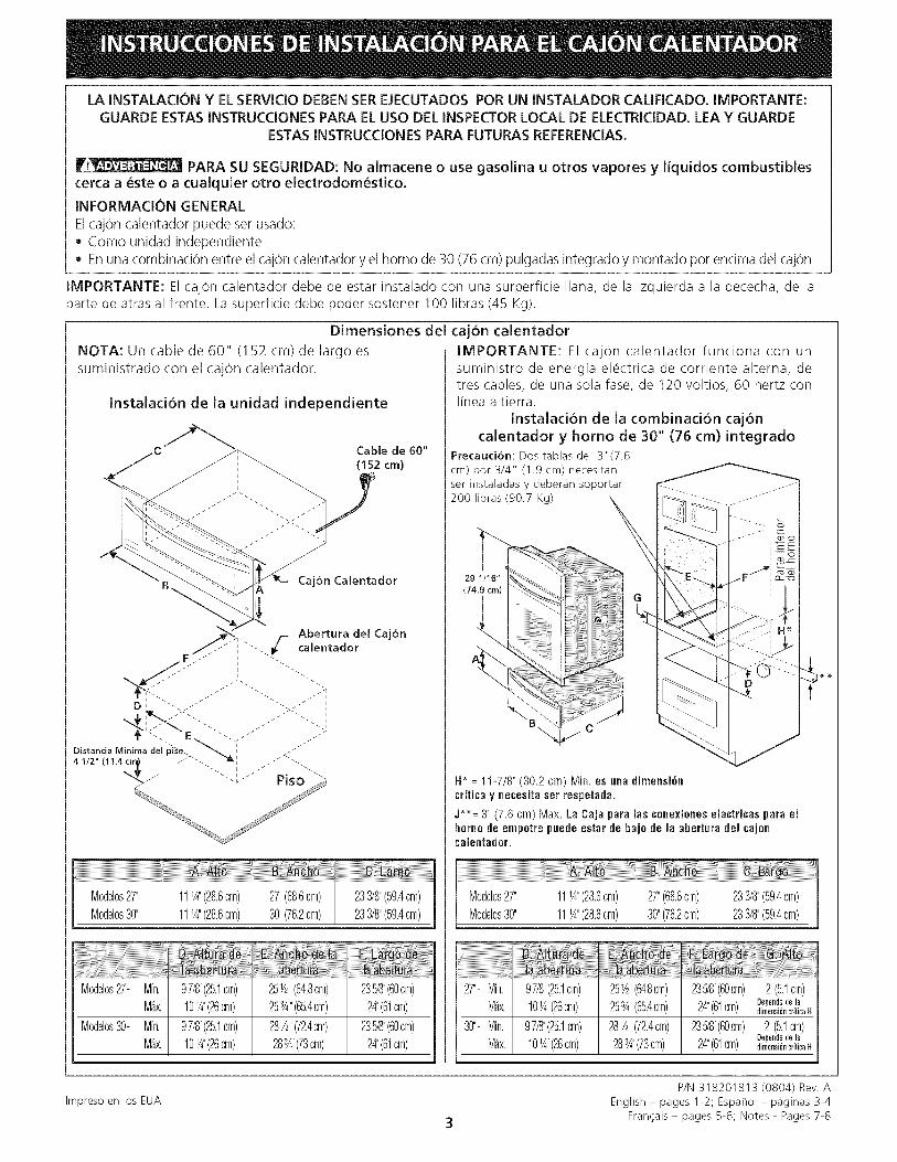
INFORMAClON GENERALElcajon calentador puede set usado:• Como unidad independiente• Enuna combinacion entre el cajon calentador y el homo de 30 (76 cm) pulgadas integrado y montado por encima del cajon
IMPORTANTE: El cajon calentador debe de estar instalado con una surperficie liana, de la izquierda a la dececha, de laparte de atr_is al frente. La superficie debe poder sostener 1OOlibras (45 Kg).
Dimensiones del cajon calentador
NOTA: Un cable de 60" (152 cm) de largo essuministrado con el cajon calentador.
Notas importantes para el instalador1. Lea todas las instrucciones de instalacion antes de
instalar el electrodomestico.
2. Retire todos los materiales de empaque clelelectrodomestico antes de conectar la fuente de energia.
3. Observe todos los codigos y leyes del gobierno4. Aseg0rese de dejarle estas instrucciones al consumidor.
Nota importante para el consumidorGuarcle estas instrucciones para futura referencia.
INSTRUCCIONES
IMPORTANTES DE SEGURIDAD• Aseg_rese de que su electrodom_stico est_ instalado y
conectado en un tomacorriente de 120 voltios con tierra.
• Este electrodom_stico debe set puestoel_ctricamente a tierra de acuerdo con el CodigoNacional El_ctrico ANSI/NFPA No 7--de la _ltimaedicion de los Estados Unidos, o la CSA C22.1, Parte1 en Canada, y con los requisitos de codigos locales.
Herramientas que usted necesitaDestornillaclor de estrella (Phillips)L_ipizRegla o cinta medidora y regla rectaSerrucho manual o serrucho de sable
Nivel de burbuja
/
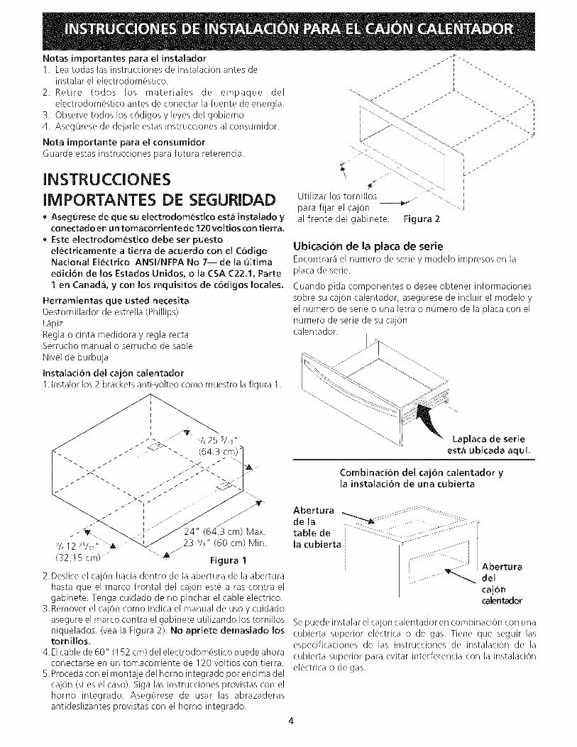
Utilizar los tornillos
para fijar el caj0nal frente del gabinete. Figura 2
Ubicadon de ia plata de serieEncontrar_i el numero de serie y modelo impresos en laplaca de serie.
Cuando pida componentes o desee obtener informacionessobre su caj0n calentador, aseg0rese de incluir el modelo yel numero de serie o una letra o numero de la placa con elnumero de serie de su caj0ncalentador.
Instalacion del cajon calentador1.Instalor los 2 brackets anti-volteo como muestro la figura 1.
Laplaca de serieest_ ubicada aqui.
Combinaci6n del caj6n calentador yla instalaci6n de una cubierta
J
.-_ 24" (64.3 cm) Max.
% 12 21/32,, _23 %" (60 cm) Min.
(32.15 cm) ........ _" Figura 1
2.Deslice el caj0n hacia dentro de la abertura de la aberturahasta que el marco frontal del cajon este a ras contra elgabinete. Tenga cuidado de no pinchar el cable electrico.
3. Remover el cajon como indica el manual de uso y cuidadoasegure el marco contra el gabinete utilizando los tornillosniquelados. (vea la Figura 2). No apriete demasiado lostornillos.
4. Elcable de 60" (152 cm) del electrodomestico puede ahoraconectarse en un tomacorriente de 120 voltios con tierra.
5.Proceda con el montaje del homo integrado pot encima delcaj0n (si es el caso). Siga las instrucciones provistas con elhomo integrado. Asegurese de usar las abrazaderasanticleslizantes provistas con el homo integraclo.
A ber t u ra .... : :=::_::=:=:'_"_- --.....
d e la _____ o-.... . <::?:::::<:--?:o<...................table de -<:_<__ _.....la cubierta --_:z............ .-o......]
/Aberturadel
cajoncalentador
Sepuede instalar el caj0n calentador en combinaci0n con unacubierta superior electrica o de gas. Tiene que seguir lasespecificaciones de las instrucciones de instalaci0n de lacubierta superior para evitar interferencia con la instalaci0nelectrica o de gas.
L'iNSTALLATION ET L'ENTRETiEN DOIVENT f:TRE EFFECTU!_S PAR UN INSTALLATEURCOMPETENT. iMPORTANT : CONSERVEZ CES iNSTRUCTiONS POUR L'INSPECTEUR D'ELECTRICITE
LOCAL. LISEZ ET CONSERVEZ CES iNSTRUCTiONS POUR RI'=FERENCES ULTERIEURES.
POUR VOTRE SECURITE: N'entreposez et n'utilisez pas d'essence ou autres gaz etliquides inflammables a proximit6 de cet appareil ou de tout autre appareil m6nager.
RENSEIGNEMENTS GENI_RAUX
Ce tiroir-rechaud peut _tre utilise comme:• Appareil autonome
Tiroir-rechaud combine aun four encastre de 30" (76 cm) superpose
IMPORTANT: Le tiroir-rechaud dolt _tre installe sur une surface de niveau, de gauche a droite et de I'arriere a I'avant. Lasurface dolt pouvoir supporter 1O0 Ibs (45 Kg).
Dimensions du tiroir-r_chaud
NOTE: Un c_ble de 60" (152 cm) est foumi avec le tiroir-rechaud.
IMPORTANT: Le tiroir-rechaud fonctionne seulementavec un circuit electrique mis a la terre a 3 ills de 120volts, monophase, 60 Hz CA.
Combin_ tiroir-r_chaud/four encastr_ de 30" (76 cm)
ATTENTION: Deux planches de 3"(7.6 cm) de large X 3/4" (1.9 cm)d'_pais doivent _tre install_es etelles doivent _tre en mesure de
supporter un poids de 200 Ibs.(90.7 Kg)
(74_
H*= 11-7/8" (30.2 cm) Min. est I'espace reqnis entrele has de l'ouvertnre du tiroir r_chaud et le has de l'onvertnre dn four.Cette dimension est critiqne et doit _tre respect_e.
J**= 3" (7.6 cm) Max. La boite de jonction _lectriqne ponr le fourencastr_ doit _tre situ_e en has du d_coupage pout le tiroir ¢haufant.
Notes importantes a Hnstailateur1. Liseztoutes lesinstructions d'installation avant de proceder
I'installation de cet appareil.2. Retirez tout le materiel d'emballage de I'appareil avant de
brancher I'alimentation electrique.3. Observez tousles reglements et codes Iocaux applicables.4. Assurez-vous de laisser ces instructions a I'utilisateur.
Note importante a I'utilisateurConservez ces instructions pour references ulterieures.
iNSTRUCTiONS DESI CLIRITE IMPORTANTES• Assurez-vous que votre appareil est install_ et raccord_
une prise murale de 120 volts mise _ la terre.• Cet appareil dolt Ctre mis _ la terre conform_ment au
code d'_lectricit_ national ANSI/N FPA No. 70, derni_re_dition, aux lttats-Unis, ou _ PACNOR C22.1, pattie 1au Canada, et aux codes et r_glements Iocaux.
Outiis n_cessaires
Toumevis PhillipsCrayonRegle ou ruban a mesurer et equerreScie a main ou scie sauteuseNiveau a bulle
Utilisez les vis _ ..........fournies pour Figure 2fixer le chassis dutiroir a I'armoire.
Emplacement des num_ros de modele et deserie
La plaque signaletique est situee tel que montre plus has.Lors d'une commande de pieces ou pour toute demandede renseignements au sujet de votre tiroir rechaud,assurez-vous de toujours inclure les numeros de modeleet de serie inscrits sur la plaque signaletique de votreappareil.
Installation d'un tiroir-rechaud
1. Localisezles supports anti-bascule tel qu'indique a la fig. 1.
/16 "
I s
.-_ '...... 24" (64.3 cm) Max.
% 12 21/32" _23 %" (60 cm) Min.
(32.15 cm) ........ _ Figure 1
2. Glissez le tiroir dans I'ouverture du decoupage jusqu'a ceque son cadre avant soit tout contre I'armoire. Veillez a nepas coincer le cordon electrique.
3. Retirez le tiroir tel qu'explique dans le manuel d'utilisationet d'entretien et fixez lechassisdu tiroir a I'armoire a I'aide
des 3 vis plaquees au nickel fournies. Ne serrez pas lesvis outre mesure (voir fig. 2)
4. Le cordon d'alimentation de I'appareil de 60" (152 cm)peut a present @trebranche a la prise murale de 120 volts.
5. Procedezmaintenant aumontage dufourencastre superposeau tiroir-rechaud (s'il y a lieu). Suivez les instructionsd'installation fournies avec le four encastre. Assurez-vousd'utiliser les crochets anti-bascule fournis avec le four.
Emplacement de laplaque signal_tique
installation combin_tiroir-r_chaud / table de cuisson
Vous pouvez installer le tiroir-rechaud en combinaisonavec une table de cuisson electrique ou gaz, en respectantles contraintes imposees par le feuillet d'installation decette table afin d'eviter certaines interferences avec


![RollOver (70.249) [Regla Final Directa]](https://static.documents.pub/doc/80x56/5695cf181a28ab9b028c93a3/rollover-70249-regla-final-directa.jpg)

