21
PVC Installation and Tapping For Potable Water and Sanitary Sewer Handling and Installation Practices Manual

PVC Installation and Tapping
For Potable Water and Sanitary Sewer
Handling and Installation Practices Manual

i
Table of Contents Introduction .....................................................................................................................................1 Shipping and Handling ...................................................................................................................1 Handling and storage of pipe and fittings ...........................................................................1 Required Markings ..............................................................................................................2 Pipe Installation - Gasketed Joint ...................................................................................................3 General ................................................................................................................................3 Equipment ...........................................................................................................................3 Procedures - Assembly .......................................................................................................3 Procedures - Field-Cutting ..................................................................................................8 Water Saddle Tapping ...................................................................................................................11 General ..............................................................................................................................11 Equipment .........................................................................................................................11 Why a core cutter?.............................................................................................................12 Procedures .........................................................................................................................13 Sewer Tapping ..............................................................................................................................16 General ..............................................................................................................................16 Equipment .........................................................................................................................16 Procedures .........................................................................................................................16 Cold Weather Considerations .......................................................................................................19

1
Introduction The purpose of this manual is to provide a brief overview of the handling and installation of PVC pipe and fittings. This is manual is primarily for familiarization purposes, and should not be considered a technical manual on PVC installation. More detailed information about PVC pipe and fittings is available in AWWA Manual 23: PVC Pipe - Design and Installation, the Uni-Bell Handbook of PVC Pipe, and other AWWA Standards. This document utilizes information found in various manuals for PVC installation published by Uni-Bell, Ipex, CertainTeed, and other industry resources. Shipping, Handling, and Storage Scratches to a maximum depth of 10% the thickness of the fitting wall shall be permitted. The following measures should be taken to avoid damage to PVC materials. 1) PVC fittings shall be packaged in crates or boxes to minimize possible damage during shipment. PVC pipe unit packages should be supported by racks or dunnage to prevent damage to the bottom during storage. 2) A forklift, or front-end loader or a backhoe with forks, may be used to move the pipe. Ensure the forks are fully engaged, and that the fork ends do not strike adjacent units. 2) A spreader bar with fabric straps or padded cables approximately eight (8) feet apart may be used to unload and move pipe. When unloading and moving PVC pipe, do not handle pipe with single chains or cables, even if padded. Do not attach cables to unit frames or banding for lifting. 3) Fittings and pipe are not to be dropped or tossed when unloading or lowering into the trench for reasons of safety and to preserve structural integrity of the item. 4) When exposure in excess of two years to direct sunlight is anticipated, PVC pipe and fittings should be covered with an opaque material. Ensure there is adequate air circulation around the PVC to prevent excessive heat accumulation. 5) PVC should not be stored close to heat sources or hot objects such as heaters, boilers, steam lines, engine exhaust, etc.

2
Required Markings Fittings shall have the following identification markings, applied in such a manner that the markings will remain legible during normal handling, storage, and installation. The markings shall be applied such that the strength of the product is not reduced. See Figure 1 for an example of required markings.
1) Nominal size and deflection angle if applicable (e.g.: 8-in Tee)
2) PVC
3) AWWA Identification number (ANSI/AWWA C900, C905)
4) Pressure class/ Diameter Ratio (e.g.: PC150, DR 18)
5) Manufacturer’s name or trademark and production record code.
6) Mark of testing agency that verified the suitability of the fitting for potable water.
7) Insertion depth reference mark - also called “insertion line”, “stop mark”, or “assembly stripe”.
Figure 1 - Required Markings on PVC Pipe
3
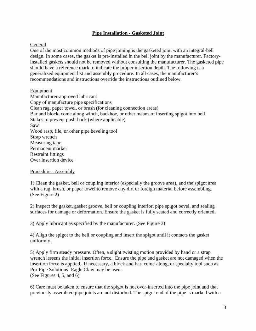
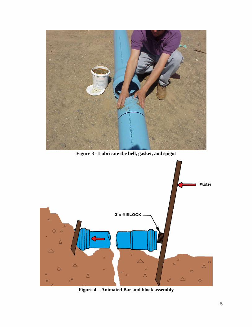
Pipe Installation - Gasketed Joint General One of the most common methods of pipe joining is the gasketed joint with an integral-bell design. In some cases, the gasket is pre-installed in the bell joint by the manufacturer. Factory-installed gaskets should not be removed without consulting the manufacturer. The gasketed pipe should have a reference mark to indicate the proper insertion depth. The following is a generalized equipment list and assembly procedure. In all cases, the manufacturer’s recommendations and instructions override the instructions outlined below. Equipment Manufacturer-approved lubricant Copy of manufacture pipe specifications Clean rag, paper towel, or brush (for cleaning connection areas) Bar and block, come along winch, backhoe, or other means of inserting spigot into bell. Stakes to prevent push-back (where applicable) Saw Wood rasp, file, or other pipe beveling tool Strap wrench Measuring tape Permanent marker Restraint fittings Over insertion device Procedure - Assembly 1) Clean the gasket, bell or coupling interior (especially the groove area), and the spigot area with a rag, brush, or paper towel to remove any dirt or foreign material before assembling. (See Figure 2) 2) Inspect the gasket, gasket groove, bell or coupling interior, pipe spigot bevel, and sealing surfaces for damage or deformation. Ensure the gasket is fully seated and correctly oriented. 3) Apply lubricant as specified by the manufacturer. (See Figure 3) 4) Align the spigot to the bell or coupling and insert the spigot until it contacts the gasket uniformly. 5) Apply firm steady pressure. Often, a slight twisting motion provided by hand or a strap wrench lessens the initial insertion force. Ensure the pipe and gasket are not damaged when the insertion force is applied. If necessary, a block and bar, come-along, or specialty tool such as Pro-Pipe Solutions’ Eagle Claw may be used. (See Figures 4, 5, and 6) 6) Care must be taken to ensure that the spigot is not over-inserted into the pipe joint and that previously assembled pipe joints are not disturbed. The spigot end of the pipe is marked with a

4
reference mark by the manufacturer to indicate the proper depth of insertion. In a properly assembled pipe-to-pipe joint, the reference mark on the spigot is visible and flush with the lip of the adjoining bell or coupling (see Figure 7) Note: The reference mark is intended for pipe-to-pipe joints using two pipes from the same manufacturer. If two different brands of pipe are being used, the depth of insertion is determined by the receiving (bell) pipe. The spigot of the pipe may require modification. 8) Use proper over insertion device to prevent over insertion for pipes in pressurized systems like water mains and sewer force mains. 7) If the reference mark does not position properly or there is undue resistance to the insertion of the spigot, disassemble the joint and check the position of the gasket. If the gasket is pushed out of its seat or twisted, inspect the components, repairing or replacing damaged parts as necessary. Clean the parts and repeat the assembly steps. Ensure both pipe lengths are properly aligned. Verify the insertion mark on the spigot pipe is in the correct location, relocating as necessary. If the ambient air temperature is 40° or below, the gasket may be stiff due to cold. See Cold Weather Considerations for more details. Note: The proper insertion depth of fittings is often different than that of a pipe. Insertion depth varies from pipe manufacture to pipe manufacturer and must be checked for each job and change in pipe manufactures.
Figure 2 - Clean the bell interior and spigot
5
Figure 3 - Lubricate the bell, gasket, and spigot
Figure 4 – Animated Bar and block assembly

6
Figure 5 - Bar and block assembly
Figure 6 - Eagle Claw Pipe Joining Tool

7
Figure 7 - Properly inserted pipe joint with cut-away
Figure 8 - Series 5000 Mega-Stop™ installed with the insertion line showing. Series 2600
PVC Restraint from EBAA Iron installed in junction for this joint
8
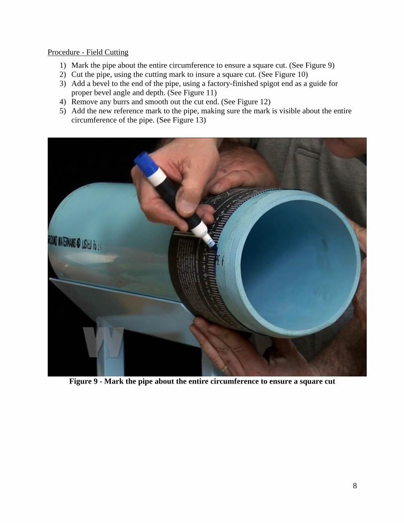
Procedure - Field Cutting
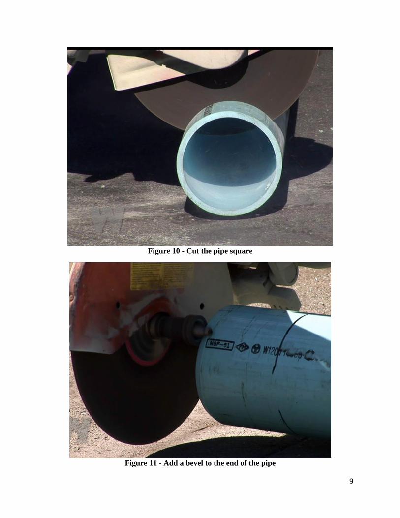
1) Mark the pipe about the entire circumference to ensure a square cut. (See Figure 9) 2) Cut the pipe, using the cutting mark to insure a square cut. (See Figure 10) 3) Add a bevel to the end of the pipe, using a factory-finished spigot end as a guide for
proper bevel angle and depth. (See Figure 11) 4) Remove any burrs and smooth out the cut end. (See Figure 12) 5) Add the new reference mark to the pipe, making sure the mark is visible about the entire
circumference of the pipe. (See Figure 13)
Figure 9 - Mark the pipe about the entire circumference to ensure a square cut
9
Figure 10 - Cut the pipe square
Figure 11 - Add a bevel to the end of the pipe

10
Figure 12 - Remove any burrs and smooth out rough areas
Figure 13 - Add a new insertion reference mark

11
Water Saddle Tapping General AWWU requires that all taps of PVC pipe use tapping saddles, such as the Romac 306 or equal. The tapping sleeves should be designed for tapping PVC water pipes. The saddle must support the pipe about its entire circumference. The saddle must not have any serrations that may damage the pipe. The saddle must not have any distorted bearing points after tightening. The threads for the tap, tapping saddle, and corporation must have AWWA threads. The cutting and tapping tool must suitable for PVC pipe, and retain the plug of material removed from the pipe wall (See Figure 8 for an example of an acceptable cutter).
Figure 14 - ROMAC 306 Stainless Steel 1” CC tapping saddle
Equipment Tapping Machine - must have tapered AWWA Threads and independent cutter feed. Slotted Core-cutting Tool, Shell Design - Minimum 2 slots - See Figure 14 for an example. Corporation Stop Manufacturer-approved tapping lubricant Teflon Tape - Pipe dope is NOT a substitute. Tapping Saddle

12
Figure 15 - Two Acceptable Slotted Core-Cutters. The cutter on the right is a combined cutter-tap
Why a core cutter? Core cutters with two or more slots are recommended because slotted cutters drill more concentric holes and the clear chips better. Slotted cutters do no cut holes faster.
Desirable Characteristics for a Slotted Core Cutter - Note the cutter is clearly marked as a 1 inch PVC cutter, has the minimum two slots for chip clearing, and has threads on the inside of the cutter to ensure positive coupon retention. Also note there is a center bit to act as a guide to prevent the cutter from wandering.

13
IN NO CASE SHOULD A TWIST DRILL BIT, SPADE DRILL BIT, OR HOLE SAW DESIGNED FOR STEEL BE USED ON PVC PIPE. Procedure - Saddle Tapping IN ALL CASES THE TAPPING MACHINE MANUFACTURE’S INSTRUCTIONS SHOULD BE FOLLOWED FOR SAFE OPERATION. IN NO CASE SHOULD A HAND-HELD DRILL BE USED. IN NO CASE SHOULD A TWIST DRILL BIT OR SPADE DRILL BIT BE USED. 1) Verify the tap will be in an appropriate location. A tap must be at least 24 inches from the end of the pipe, at least 2 inches from other taps axially (along the length of the pipe), and at least 2 inches apart radially (about the girth of the pipe). Alternately the taps may be 36” apart with no separation radially. Multiple taps on the same side of the pipe must be staggered. See Figure 15 for an illustration. 2) Verify the saddle closely conforms to the pipe. There should be no gaps or high/low spots on the pipe. 3) Attach the drilling machine to the pipe according to the manufacturer’s instructions. This generally involves: a) Attach the saddle to the main, tightening each side in turn until tightened with the same amount of torque, ensuring the saddle remains level on the pipe. b) Verify the saddle is level on the pipe. See Figure 14 for illustration. c) Verify the pipe is not deformed due to over tightening. 4) Attach the correct size shell cutter or comparable tapping cutter to the drilling machine. 5) Lightly lubricate the outside of the cutter with NSF 61 certified pipe lubricant. 6) Using steady even pressure, drill the hole in the pipe. After each cut, remove the coupon and chips from the cutter. Examine the PVC coupon - a smooth edge means a good cut was made.

14
7) Verify that the tap is of the correct size, has AWWU threads, and is in good condition. 8) Attach the tap to the tapping machine and lubricate. 9) Using steady even pressure, tap the hole in the pipe. After each tapping operation, remove the tap and clear the chips out of the new threads and cutter before inserting the corp.
Figure 16 - Diagram of Permissible Tapping Area

15
Figure 17 - Tapping Machine Orientation

16
Sewer Tapping
General AWWU requires that all sewer pipe taps use tapping saddles or sleeves. When the tap is done between 22.5⁰ and 45⁰ from the spring line a Romac CB Sewer Saddle or equal is to be used. When the tap is done vertically, a Romac SST tapping sleeve or equal is to be used. The tapping saddle/sleeve should be designed for tapping PVC sewer pipes. The saddle/sleeve must support the pipe about its entire circumference. The saddle/sleeve must not have any serrations that may damage the pipe. The saddle/sleeve must not have any distorted bearing points after tightening. Equipment Manufacturer-approved tapping lubricant Tapping Sleeve/Saddle Hole saw Power Drill Sabre Saw Torque wrench & sockets Procedure:
1) Verify the tap will be in an appropriate location. A tap must be at least 24 inches from the end of the pipe, at least 36 inches from other taps axially (along the length of the pipe). Multiple taps on opposite sides of the pipe must be staggered a minimum of 18” apart.
2) Check the diameter of the main and branch pipe to make sure you are using the correct size saddle gasket. Also check the gasket to make sure it is the size you think that you need.
3) Make sure no foreign materials lodge between saddle gasket and pip. 4) Place the saddle in position on the pipe and mark a guideline for the hole cut-in, using the
saddle hole as a template. Remove the saddle from the pipe. 5) Using the hole guide mark, cut the hole through the pipe using a sabre saw or power drill
with a hole saw. The hole should be no larger than the inside diameter of the saddle gasket.
6) Place lubricant around the hole and place saddle into position and secure with straps, nuts and bolts.
7) Tighten nuts evenly, alternating between them until the appropriate torques is reached. Over tightening can deform the PVC and is to be avoided.
8) Heat the area if the saddle gasket below 45⁰F. 9) Bevel exposed edges of the main line to reduce the chance of sewer hanging up on rough
edges.

17
Figure 18 – Typical Sewer Service
Figure 19- ROMAC CB Saddle

18
Figure 20 - ROMAC SST 8”x4” Tapping Sleeve w/restrained riser

19
Cold Weather Considerations
When the ambient temperature drops below 40° F, the gaskets on the push-on pipe begin to get very stiff, making it difficult to stab the pipe to the correct length. Steady, firm, easily controllable pressure, such as that provided by a come along winch or a bar and block (see Joint Assembly for details), is recommended to prevent over-stabbing. Alternatively, the gaskets can be stored in a warm truck or heated job shack to insure the gaskets remain supple. PVC becomes more brittle below 40° F, necessitating more care during the handling and installation of fittings and taps to avoid cracking.


