Installation and Thermal Feedback from a Multi-wavelength Pyrometer in Electron Beam Melting Jonathan Minjares 1 , Jorge Mireles 1 , Sara M. Gaytan 1 , David Espalin 1 , William T. Carter 2 , and Ryan B. Wicker 1 1 W.M. Keck Center for 3D innovation, The University of Texas at El Paso, El Paso, Texas, 79968 2 GE Global Research, Niskayuna, NY, 12309 Abstract The purpose of this paper is to outline and discuss the installation and use of a multi-wavelength pyrometer for process temperature monitoring in Electron Beam Melting (EBM). A multi-wavelength pyrometer was externally mounted atop an EBM system to observe and record surface temperatures during the fabrication process. The multi-wavelength pyrometer is a non-contact device capable of measuring the temperature of an object without the need of knowing the object’s emissivity. Temperature data from the EBM system thermocouple and the multi-wavelength pyrometer were compared, and it was determined that the pyrometer measurements were reasonable. During fabrication, the multi-wavelength pyrometer allowed the characterization of the EBM process that consisted of various steps during fabrication (e.g. heating of the build platform, powder deposition, and melting). Measurement of surface temperatures during fabrication can be useful for parameter development of novel materials, prediction of resulting microstructural architectures, and ultimately as feedback used in a closed-loop control system, allowing full spatial and temporal control of melting and microstructure. 1. Introduction Additive manufacturing (AM) is a process that consists of adding layers of a material to create a solid 3D object starting from a computer-aided-design (CAD) (Sclater and Chironis, 2006). The Electron Beam Melting (EBM) process is an AM technology to develop end-use metal components in industries, such as aerospace, biomedical, electrical, and automotive (Gibson et al., 2010). Material development on this system is of significant interest, because it can inherently produce dense parts with reduced residual stresses compared to similar powder fusion processes like selective laser melting. However, material development is not trivial and can benefit from added process feedback. In commercial EBM systems, temperature feedback consists of a single thermocouple that measures the temperature below the build platform. However, since the EBM is a layer-by-layer process, the temperature readings are not representative of the layer being fabricated and do not show the surface temperatures to perceive any effect on the quality of the part (e.g. microstructure variations from different thermal conditions). When developing processing parameters or attempting to control microstructure, it is important to know the surface temperature during fabrication. With the added capability of knowing the temperature for each process step, the operator can modify system parameters to obtain a desired surface temperature. Methods to understand the temperature of the forming layer have been attempted to analyze the thermal environment of the EBM system while fabricating. In a study conducted by Price et al. (2013)., an infrared (IR) camera was used in an EBM system to analyze the melt pool sizes and temperature distributions around the melting area at various configurations, finding peak temperatures during the melting step, molten pool emissivity, and small differences in temperature profiles as the build increases in height. Additionally, Rodriguez (2013) recorded thermal images to obtain the post-melting temperature of the forming by utilizing an IR camera with a specified emissivity value for EBM while processing Ti- 6Al-4V. Utilization of an IR camera in EBM has allowed analysis of thermal images to detect defects such as porosity and the development of automated control for microstructure and process control (Mireles, 2013). The studies performed by Rodriguez and Mireles utilized a shutter mechanism to avoid metallization of the view window, due to elements condensing and evaporating from the melt pool. Oak Ridge National Laboratory developed a shutterless mechanism to obtain real-time thermal images using a moving Mylar film canister to improve the reliability of the EBM process (Dinwiddie, et al., 2013). 288
Transcript
Installation and Thermal Feedback from a Multi-wavelength Pyrometer in Electron Beam Melting
Jonathan Minjares1, Jorge Mireles
1, Sara M. Gaytan
1, David Espalin
1, William T. Carter
2, and Ryan B.
Wicker1
1W.M. Keck Center for 3D innovation, The University of Texas at El Paso, El Paso, Texas, 79968
2GE Global Research, Niskayuna, NY, 12309
Abstract
The purpose of this paper is to outline and discuss the installation and use of a multi-wavelength
pyrometer for process temperature monitoring in Electron Beam Melting (EBM). A multi-wavelength
pyrometer was externally mounted atop an EBM system to observe and record surface temperatures
during the fabrication process. The multi-wavelength pyrometer is a non-contact device capable of
measuring the temperature of an object without the need of knowing the object’s emissivity. Temperature
data from the EBM system thermocouple and the multi-wavelength pyrometer were compared, and it was
determined that the pyrometer measurements were reasonable. During fabrication, the multi-wavelength
pyrometer allowed the characterization of the EBM process that consisted of various steps during
fabrication (e.g. heating of the build platform, powder deposition, and melting). Measurement of surface
temperatures during fabrication can be useful for parameter development of novel materials, prediction of
resulting microstructural architectures, and ultimately as feedback used in a closed-loop control system,
allowing full spatial and temporal control of melting and microstructure.
1. Introduction
Additive manufacturing (AM) is a process that consists of adding layers of a material to create a
solid 3D object starting from a computer-aided-design (CAD) (Sclater and Chironis, 2006). The Electron
Beam Melting (EBM) process is an AM technology to develop end-use metal components in industries,
such as aerospace, biomedical, electrical, and automotive (Gibson et al., 2010). Material development on
this system is of significant interest, because it can inherently produce dense parts with reduced residual
stresses compared to similar powder fusion processes like selective laser melting. However, material
development is not trivial and can benefit from added process feedback. In commercial EBM systems,
temperature feedback consists of a single thermocouple that measures the temperature below the build
platform. However, since the EBM is a layer-by-layer process, the temperature readings are not
representative of the layer being fabricated and do not show the surface temperatures to perceive any
effect on the quality of the part (e.g. microstructure variations from different thermal conditions). When
developing processing parameters or attempting to control microstructure, it is important to know the
surface temperature during fabrication. With the added capability of knowing the temperature for each
process step, the operator can modify system parameters to obtain a desired surface temperature.
Methods to understand the temperature of the forming layer have been attempted to analyze the
thermal environment of the EBM system while fabricating. In a study conducted by Price et al. (2013).,
an infrared (IR) camera was used in an EBM system to analyze the melt pool sizes and temperature
distributions around the melting area at various configurations, finding peak temperatures during the
melting step, molten pool emissivity, and small differences in temperature profiles as the build increases
in height. Additionally, Rodriguez (2013) recorded thermal images to obtain the post-melting temperature
of the forming by utilizing an IR camera with a specified emissivity value for EBM while processing Ti-
6Al-4V. Utilization of an IR camera in EBM has allowed analysis of thermal images to detect defects
such as porosity and the development of automated control for microstructure and process control
(Mireles, 2013). The studies performed by Rodriguez and Mireles utilized a shutter mechanism to avoid
metallization of the view window, due to elements condensing and evaporating from the melt pool. Oak
Ridge National Laboratory developed a shutterless mechanism to obtain real-time thermal images using a
moving Mylar film canister to improve the reliability of the EBM process (Dinwiddie, et al., 2013).
288
The work from these authors focuses on infrared emissions as a source of thermal information;
however, varying factors such as radiant temperature and emissivity can affect the thermal measurement.
A multi-wavelength pyrometer was used in this research, which is a device that calculates the surface
temperature of a target object without the need of knowing emissivity. A multi-wavelength pyrometer
was externally mounted atop an EBM system to monitor the surface temperature during the fabrication
process. Temperature data from the pyrometer was compared to that of a thermocouple. The pyrometer
allowed the characterization of the EBM process, such as powder deposition, preheating, melting, and
cooling during layer-by-layer fabrication. This information can be useful when developing and improving
parameters for a new material or to improve its mechanical properties by further controlling the thermal
environment during fabrication. Furthermore, the temperatures profiles obtained can give an
approximation of the solidification phenomena that occurs during each layer, which may be useful to
achieve full spatial and temporal control of microstructure.
2. Methodology
2.1 EBM system
EBM consists of several steps to fabricate a part (powder deposition, preheating, and melting).
First, a layer (~0.07mm in thickness) of powder is deposited into the build platform by a powder
deposition mechanism. The electron beam preheats the powder to about 50% of the melting temperature
of the alloy (~760°C for Ti-6Al-4V), which is used to sinter the powder around the part to hold the part
during the fabrication process (Cormier et al., 2004). Furthermore, preheating helps decrease the thermal
gradient between layers and throughout the overall part, thus, reducing thermal stresses (Cormier et al.,
2004). After the preheat cycle, the electron beam melts the metal powder following the 2D cross section
from a sliced computer-aided design (CAD) model. The start plate is lowered by the thickness of one
layer and the steps of powder deposition, preheating, and melting are repeated until fabrication is
complete (Cormier et al., 2004).
2.2 Multi-wavelength pyrometer
The pyrometer specified in this study has been previously used to measure processing
temperature of metals in hostile thermal environments where the emissivity is changing or unknown such
a) Pyrometer on the EBM system
40 mm
b) Start plate and pyrometer setup
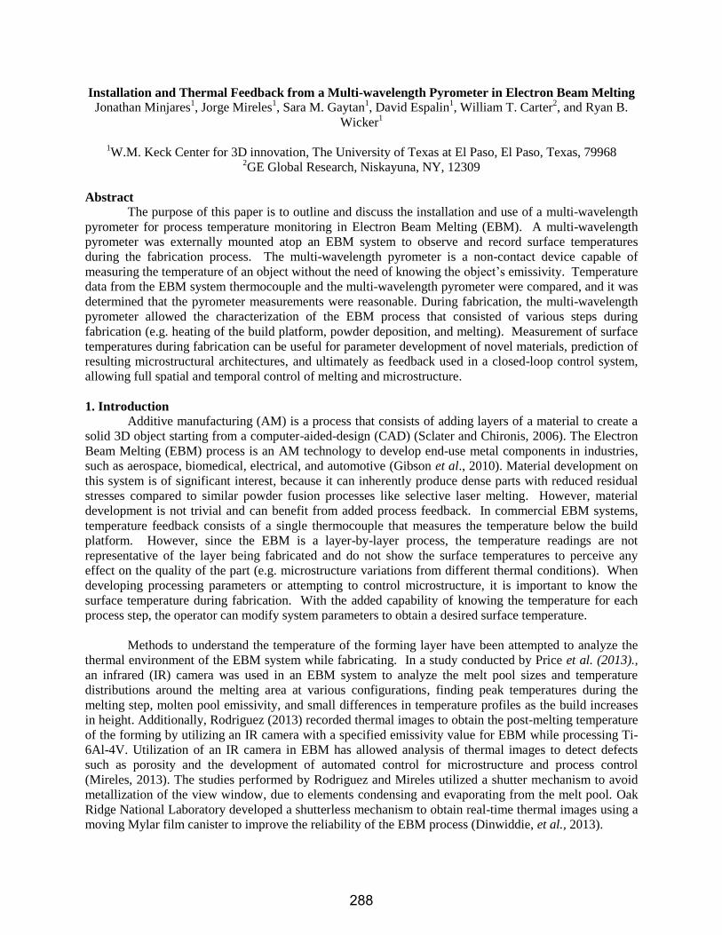
Figure 1 a) Pyrometer setup schematic, b) laser spot specifying area where
pyrometer obtained data
rake
measurement
area build
platform
430 mm
289
as investment casting. The multi-wavelength pyrometer has been able to identify and discard radiation
affected by the process’s gas emissions or absorptions (Felice, 2006). The pyrometer is a non-contact
device capable of measuring the temperature of an object without the need of knowing emissivity, or the
object’s surface ability to emit radiant energy (Felice, 2002). To automatically determine an emissivity,
the instrument measures the target object’s wavelengths to calculate a temperature whose radiance curve
is compared to an ideal Planck curve. If the curve matches, the target is said to be an ideal blackbody
(emissivity=1), otherwise the radiance corresponds to a non-blackbody and emissivity is automatically
calculated to match a Planck curve. In this research, the multi-wavelength pyrometer was externally
mounted atop an EBM system pointing to the build platform within the vacuum chamber through a quartz
window (which allowed ~99% transmission for detected wavelengths) (Figure 1a). For all experiments
presented in this paper, the pyrometer was pointed to the middle of the build platform and all recorded
temperature data corresponded to the part fabricated at that location. Figure 1b illustrates the position of
the pyrometer where the spot within the build platform is the measurement area (~2mm diameter) of the
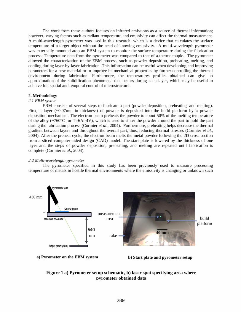
pyrometer. The multi-wavelength pyrometer functions by using a fiber optic cable that directs light to the
object whose temperature is being measured and detects the wavelengths emitted by using a
spectrophotometer that separates the detected wavelengths. By employing an electrical transmission line,
the information is sent to the device’s analog-to-digital conversion system, which computes and reports
temperature, tolerance, and signal strength that is displayed in a desktop computer. Figure 2 illustrates
the schematic of the multi-wavelength pyrometer used in this study. The multi-wavelength pyrometer is
able to measure temperatures in the range of 300°C to 2,000°C. While measuring, the pyrometer displays
and records 1) temperature of the target object (in °C), 2) tolerance of the measured temperature (standard
deviation), and 3) signal strength (an emissivity value at a certain wavelength) (Felice, 2003).
2.3 Installation of pyrometer on EBM system
In its commercial state, the EBM system includes a standard video camera to observe part
fabrication that was removed to install the multi-wavelength pyrometer. Fixtures and brackets were
designed and fabricated to maintain a good seal on the top of the chamber and ensure the system was able
to obtain appropriate vacuum levels for fabrication (~10-4
torr). The fixture consisted of a stainless steel
ring that fit the outside contour of the quartz glass, and two aluminum brackets were used to press the
fixture onto the glass using screws. A quartz glass (~70mm in diameter by ~10mm in thickness) was
Figure 2. Schematic of the multi-wavelength pyrometer
The multi-wavelength pyrometer
290
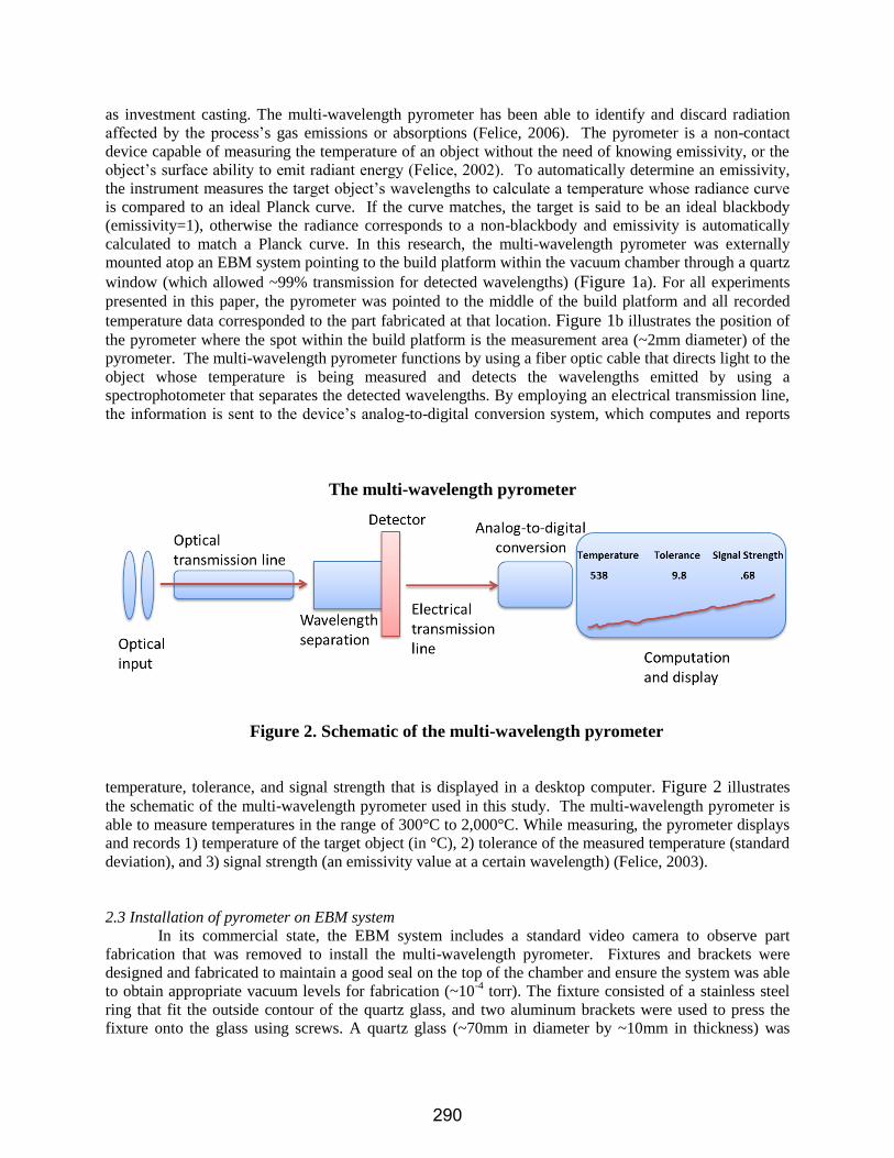
utilized to obtain optimum transmission of light waves. Figure 3a illustrates the pyrometer looking
thorough the inside of the system and Figure 3b shows the fixture and the bracket installed on the
system.
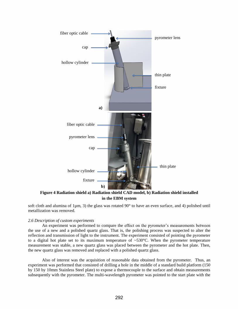
2.4 Radiation shielding
During the fabrication process, X-rays are emitted by electrons generated from the electron beam.
The vacuum chamber, the lead-coated glass windows, and the heat shields are specifically designed to
enclose the emitted X-rays, allowing the external emissions to remain within approved levels. Installation
of a radiation shield was crucial to prevent radiation exposure of harmful X-rays to the EBM user since
the original bracket from the camera was removed, and the lead-coated glass was replaced with a quartz
glass. The shield design consisted of a thin plate with a curvature around the quartz glass fixture and a
hollow cylinder on top of the fixture to prevent radiation exposure and hold the pyrometer in place.
Stainless steel was used for both the thin plate and the hollow cylinder and covered with lead foil. A cap
was designed to fill any space between the hollow cylinder and the pyrometer. The cap was fabricated by
AM using a U-print system and also covered with lead foil post-fabrication. Figure 4a illustrates the CAD
model for the radiation shield and Figure 4b describes the radiation shield installed on the EBM system.
Radiation levels were measured while the machine was in operation post-installation using a Geiger
counter to ensure no harmful radiation was emitted from the system.
2.5 Quartz glass metallization
The pyrometer pointed to the inside of the EBM system through a quartz glass window. When the
electron beam melts the metal powder, elements with low melting temperatures (e.g. aluminum) vaporize,
causing metallization on the quartz glass since the quartz glass is non-conductive and thus more
susceptible to metallization. After a certain period of time, metallization will decrease the accuracy of the
pyrometer to the extent where the pyrometer stops displaying data. The time of the quartz glass
metallizing depends on the size of the layer being formed. Thus, the larger the cross section being melted,
the greater the vaporization, which causes the quartz glass to metallize faster. For this reason, a process to
remove metallization was implemented. The procedure consisted of 1) cleaning the quartz glass with
isopropyl alcohol, 2) the quartz glass was polished in a standard 8 inch (203mm) rotating wheel using a
a) Pyrometer pointing inside
the EBM system
b) Fixture and brackets installed on
the EBM System
Figure 3 Pyrometer and fixture
brackets
fixture
screws quartz
glass
291
soft cloth and alumina of 1µm, 3) the glass was rotated 90° to have an even surface, and 4) polished until
metallization was removed.
2.6 Description of custom experiments
An experiment was performed to compare the effect on the pyrometer’s measurements between
the use of a new and a polished quartz glass. That is, the polishing process was suspected to alter the
reflection and transmission of light to the instrument. The experiment consisted of pointing the pyrometer
to a digital hot plate set to its maximum temperature of ~530°C. When the pyrometer temperature
measurement was stable, a new quartz glass was placed between the pyrometer and the hot plate. Then,
the new quartz glass was removed and replaced with a polished quartz glass.
Also of interest was the acquisition of reasonable data obtained from the pyrometer. Thus, an
experiment was performed that consisted of drilling a hole in the middle of a standard build platform (150
by 150 by 10mm Stainless Steel plate) to expose a thermocouple to the surface and obtain measurements
subsequently with the pyrometer. The multi-wavelength pyrometer was pointed to the start plate with the
a)
b)
Figure 4 Radiation shield a) Radiation shield CAD model, b) Radiation shield installed
in the EBM system
cap
hollow cylinder
fiber optic cable
pyrometer lens
hollow cylinder
fiber optic cable
fixture
cap
thin plate
thin plate
fixture
pyrometer lens
292
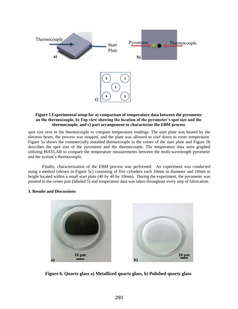
spot size next to the thermocouple to compare temperature readings. The start plate was heated by the
electron beam, the process was stopped, and the plate was allowed to cool down to room temperature.
Figure 5a shows the commercially installed thermocouple in the center of the start plate and Figure 5b
describes the spot size of the pyrometer and the thermocouple. The temperature data were graphed
utilizing MATLAB to compare the temperature measurements between the multi-wavelength pyrometer
and the system’s thermocouple.
Finally, characterization of the EBM process was performed. An experiment was conducted
using a method (shown in Figure 5c) consisting of five cylinders each 10mm in diameter and 10mm in
height located within a small start plate (40 by 40 by 10mm). During the experiment, the pyrometer was
pointed to the center part (labeled 5) and temperature data was taken throughout every step of fabrication.
3. Results and Discussions
b)
Thermocouple Pyrometer Thermocouple
Start
Plate
c)
Figure 5 Experimental setup for a) comparison of temperature data between the pyrometer
an the thermocouple, b) Top view showing the location of the pyrometer’s spot size and the
thermocouple, and c) part arrangement to characterize the EBM process
a)
10 µm 10 µm
a) b)
Figure 6. Quartz glass a) Metallized quartz glass, b) Polished quartz glass
293
The installed radiation shield was found to be effective in preventing leakage radiation. It was
found that the Geiger counter did not detect harmful levels of radiation emitted by the EBM during
operation. Furthermore, the comparison between a new and a polished quartz glass revealed the
pyrometer displayed a ~1°C temperature change that was considered negligible. Figure 6 illustrates a
metallized and a quartz glass after polishing. Future work may be performed to avoid metallization of the
quartz glass, such as implementing a revolving quartz film. The above results verified that the installation
and setup procedures of the pyrometer in EBM were safe and effective for data acquisition.
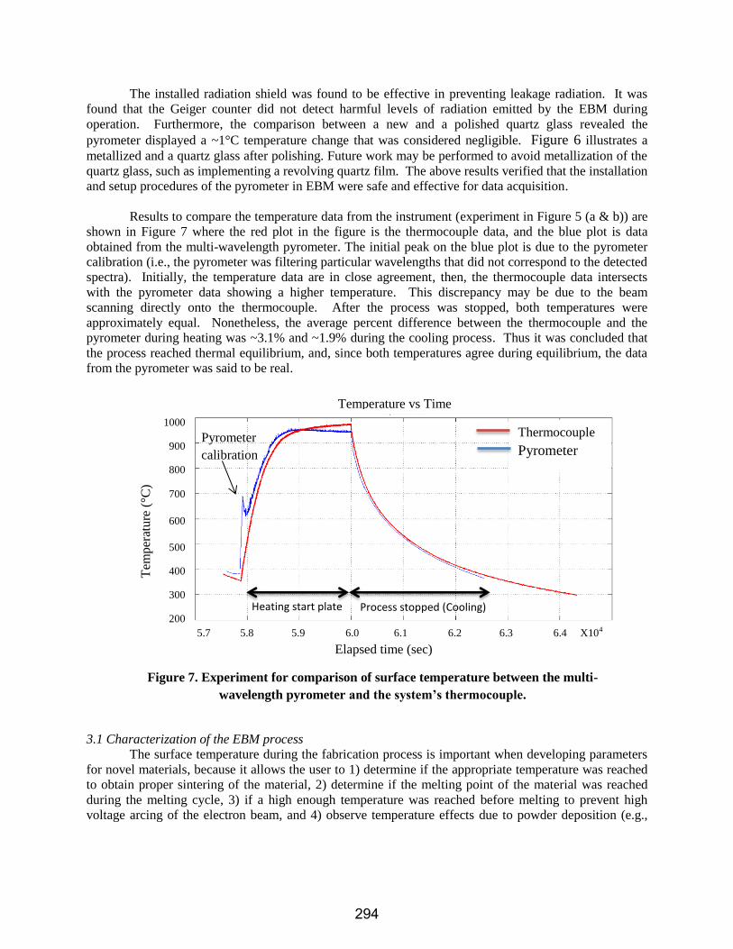
Results to compare the temperature data from the instrument (experiment in Figure 5 (a & b)) are
shown in Figure 7 where the red plot in the figure is the thermocouple data, and the blue plot is data
obtained from the multi-wavelength pyrometer. The initial peak on the blue plot is due to the pyrometer
calibration (i.e., the pyrometer was filtering particular wavelengths that did not correspond to the detected
spectra). Initially, the temperature data are in close agreement, then, the thermocouple data intersects
with the pyrometer data showing a higher temperature. This discrepancy may be due to the beam
scanning directly onto the thermocouple. After the process was stopped, both temperatures were
approximately equal. Nonetheless, the average percent difference between the thermocouple and the
pyrometer during heating was ~3.1% and ~1.9% during the cooling process. Thus it was concluded that
the process reached thermal equilibrium, and, since both temperatures agree during equilibrium, the data
from the pyrometer was said to be real.
3.1 Characterization of the EBM process
The surface temperature during the fabrication process is important when developing parameters
for novel materials, because it allows the user to 1) determine if the appropriate temperature was reached
to obtain proper sintering of the material, 2) determine if the melting point of the material was reached
during the melting cycle, 3) if a high enough temperature was reached before melting to prevent high
voltage arcing of the electron beam, and 4) observe temperature effects due to powder deposition (e.g.,
Figure 7. Experiment for comparison of surface temperature between the multi-
wavelength pyrometer and the system’s thermocouple.
Heating start plate Process stopped (Cooling)
Pyrometer
calibration
Temperature vs Time
Thermocouple
Pyrometer
5.7 5.8 5.9 6.0 6.1 6.2 6.3 6.4 X10⁴
Elapsed time (sec)
1000
900
800
700
600
500
400
300
200
Tem
per
ature
(°C
)
294
Preheating
Melt delay
Melting
Cooling
Powder deposition
a)
b)
c)
Figure 8. Characterization of the EBM process using the multi-wavelength pyrometer; a)
temperature graph; b) surface temperature pattern; c) characterization of the EBM process
Thermocouple
Pyrometer
Tem
per
ature
Time
Thermocouple Pyrometer
Thermocouple Pyrometer
Tem
per
atu
re
Tem
per
atu
re
Time
Time
295
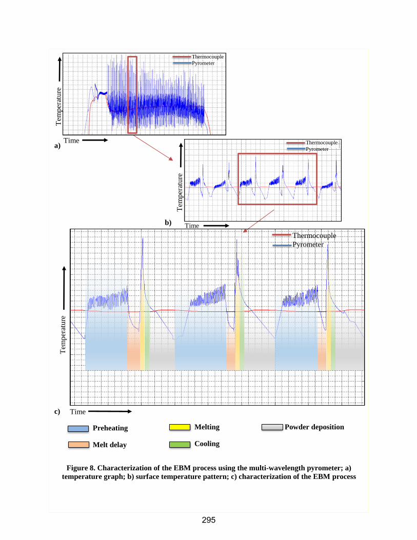
excess cooling upon powder deposition). Furthermore, the operator can ensure that a desired surface
temperature was obtained after each step to help improve process isotropy. Figure 8a shows a MATLAB
graph with the multi-wavelength pyrometer plot (blue) and the thermocouple plot (red) from the
experiment described in Figure 5c. The temperature plot from the multi-wavelength pyrometer oscillates
throughout fabrication, which can be due to the recording of data during various stages of fabrication
which yield different reflections (e.g., powder, melted surface, rake mechanism during powder deposition,
etc.). Also, the peaks that describe the melting temperature of the material are not the same every layer.
This can be caused by the time delay of the pyrometer recording the temperature data (i.e., melting occurs
faster than data logging) or inherent layer-to-layer variations (e.g., different packing of powder that yield
variations in melting process and emissivity). Figure 8b is a zoomed view from the graph in Figure 8a,
which describes the surface temperature pattern of three consecutive layers during the fabrication process.
Figure 8d is the characterization of the EBM process during this experiment. The process consisted of
preheating, part melt delay, melting, cooling, and powder deposition.
4. Conclusions
For this project, a multi-wavelength pyrometer was installed in an EBM system and the following
was achieved:
1. The multi-wavelength pyrometer was installed in an EBM system. A setup procedure was
implemented using quartz glass that helped maintain appropriate transmittance of
electromagnetic radiation. A radiation shield was designed and fabricated to prevent radiation
exposure and ensure the instrument was safely installed.
2. The multi-wavelength pyrometer data was compared to thermocouple temperature data to
determine if the pyrometer measurements were reasonable.
3. The multi-wavelength pyrometer permitted the characterization of the EBM process by
identifying the pre-heat temperature, melting temperature, cooling after melting, and powder
deposition steps which allow a better understanding of the thermal behavior during fabrication.
An advantage of using the multi-wavelength pyrometer was the capability to obtain real surface
temperature measurements without the need to know and define emissivity. The data obtained can be
ultimately used as feedback in a closed-loop control system allowing full spatial and temporal control of
microstructure through direct modification of melting. Such control can lead to components with
improved thermal isotropy and help identify resulting microstructure/mechanical properties of fabricated
parts. Furthermore, this information can help facilitate process parameter development for novel
materials using EBM or other AM technologies through the improved system feedback.
Acknowledgements The research described in this paper was performed at the W.M. Keck Center for 3D Innovation at the
University of Texas at El Paso (UTEP). Students at the Center, Philip A. Morton and Cesar A. Terrazas,
helped perform, and provided advice on, experiments pertaining to the presented research. The authors
are also thankful for additional funding of this research that was provided by GE Global Research.
References
Cormier, Denis, Ola Harrysson, and Harvey West. "Characterization of H13 steel produced via electron


![Analysis of surface compositions in the Oxia Palus region ...3.1. Thermal Emission Spectrometer [8] Thermal infrared spectral observations by the TES instrument cover the wavelength](https://static.documents.pub/doc/80x56/6096babec36252715b735f91/analysis-of-surface-compositions-in-the-oxia-palus-region-31-thermal-emission.jpg)

