The Alpha Jetstream MD is a cast iron sectional boiler for pressure jet oil or forced draught gas firing. The boiler is of the horizontal 3 pass type. The boilers are able to be utilised as low temperature boilers as described in the Boiler Efficiency Directive 92/42 EEC
MD series are CE Marked on PIN CE-0645BO119 to
Gas Appliances Directive (90/396/EEC)Boiler Efficiency Directive (92/42/EEC)Electromagnetic Compatability Directive (89/336/EEC)
and conforms the requiremets ofEN 303/1: Heating boilers with forced draught burners - Terminology, general requirements, testing and markingEN 303/2: Heating boilers - Part 2: Heating boilers with forced draught burners - Special requirements for boilers atomizing oil burnersEN 303/3: Heating boilers-Part 3: Gas fired heating boilers-Assembly comprising a boiler body and a forced draught burner
MD series boilers are suitable for central heating and indirect hot water supply at working pressures not exceeding 4 bars, and working temperatures not exceeding 100 C. The boiler must never be used for direct water supply.
MD Jetstream Cast Iron Boiler for oil and gas firing
INTRODUCTION
TECHNICAL INFORMATION
Boiler type MD 4 MD 5 MD 6 MD 7 MD 8 MD 9 Number of sections 4 5 6 7 8 9 Product-ID number– Notified body number 86/AT/572 – CE0086 Rated heat output kW 105 144 184 223 262 300 Flue gas resistance mmwg
wg4 9 16 20 23 33
Combustion diameter mm 370 chamber depth mm 450 580 715 845 975 1105 Length L mm 744 878 1012 1146 1280 1414 Burner mounting diameter mm 170 dimensions depth mm 115 Return/flow connections DN 65 (2 ½ “BSP M) Flue gas temperature oC 185 Flue connection diameter mm 208 Weight (boiler block) kg 430 510 590 670 750 830 Weight (water content) kg 49 61 73 85 96 108 Flow temperature control oC 30 – 90 Natural gas* m3/h 11.98 16.5 21.04 25.57 29.97 34.36 Fuel LPG** m3/h 8.83 12.16 15.5 18.83 22.07 25.31 Consump. 35 sec oil*** kg/h 9.7 13.35 17 20.7 24.24 27.8 Heat input to boiler
Natural gas, LPG, 35 secoil
kW 115 158 202 245 288 329
Jetstream Jetstream is a PATENTED NEW TECHNOLOGY developed particularly to prevent flue Technology gas condensation in the boiler. It is based on increasing the temperature of cool return
water into boiler & mixing it with hot circulating water inside the boiler. This is accomplished by a jet effect created by a distribution pipe fixed to the returnconnection of the boilerThe cool return water is injected into the boiler via a distribution pipe. This injection results in a pressure drop at the end of the pipe, creating a vacuum. This vacuum sucks hot delivery water of the rear section/sections down to mix with the return waterthereby raising the return water temperature. Thus, the main reason of flue gas condensation in the boiler is eliminated. Also a reverse flow of hot water in the rear section of the boiler protects the section against excessive thermal shocks.
The Alpha Jetstream MD willoperate without condensation providing the minimum return water temperatures areobserved:
Fuels Lowest return temperatures(°C)
Naural gas, LPG 35Light oil 25
TECHNICAL INFORMATION
Fluegas resistance
Efficiencies
Values given according to average boiler water temperature of 70 C
Flue gastemperatures
Values given according to average boiler water temperature 70 C, ambient temperature 20 C
TECHNICAL INFORMATION
Flue
gas
resi
stan
ce (m
bar)
100% load
75% load
50% load
LOAD
LOAD
Combustion
Overall
Oil Supply MD series boilers can only be fired with liquid fuels having following specifications:
Kerosene viscosity at 20 C: 1.2 cSt or viscosity at 100 F: 28 Second *Light oil (EL) viscosity at 20 C: 4- 6 max cSt or viscosity at 100 F: 35 SecondGasoil (D) viscosity at 20 C: 4- 6 max cSt or viscosity at 100 F: 35 Second*Burners suitable for Kerosene have limited availability and range
Any failure due to lack of technical precautions, firing with fuels not suitable for boilers, and operation without taking recommendations given further in this manual into consideration, will always be the responsibility of the end-user.A single pipe oil supply with oil at a slight positive pressure is generally required though the burners own oil pumps can provide some lift of the oil depending on the volume flow and the lift required. For dual fuel burners a two pipe oil supply system is generally recommended unless the burner is fitted with an oil pump clutch. An oil filter and isolating valve should be provided and the burner connected to the oil supply with a flexible oil hose. The hose and filter are generally supplied with the burner.
Gas Supply The local gas supply authority should always be contacted at the design state to ensure an adequate supply is available. An existing service pipe must not be used without prior consultation with the local gas supply authority and the supply must be made through a suitable meter.The matching of burner model, burner and gas train size must be carried out in accordance with supplied inlet gas pressure and fuel type to be fired. When sizing the burner and gas train, all pressure losses inside the boiler, burner and gas train, and in piping from burner inlet to main gas meter must always be taken into consideration.
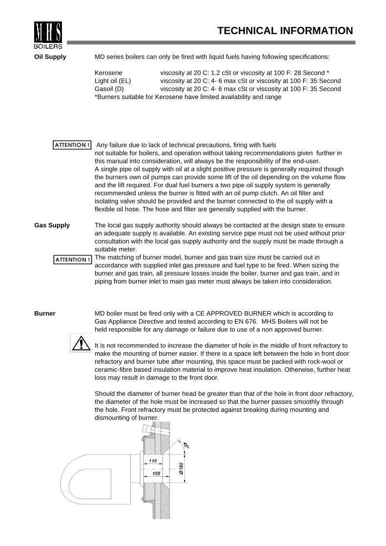
Burner MD boiler must be fired only with a CE APPROVED BURNER which is according to Gas Appliance Directive and tested according to EN 676. MHS Boilers will not beheld responsible for any damage or failure due to use of a non approved burner.
It is not recommended to increase the diameter of hole in the middle of front refractory to make the mounting of burner easier. If there is a space left between the hole in front door refractory and burner tube after mounting, this space must be packed with rock-wool or ceramic-fibre based insulation material to improve heat insulation. Otherwise, further heat loss may result in damage to the front door.
Should the diameter of burner head be greater than that of the hole in front door refractory, the diameter of the hole must be increased so that the burner passes smoothly through the hole. Front refractory must be protected against breaking during mounting and dismounting of burner.
TECHNICAL INFORMATION
Water side The fully watercooled sections are joined by cast iron conical nipples, and distribution of boiler pipe fitted to the return ensures even the temperature distribution throughout the boiler.
The cast iron sections are to BS.1452 Grade 200 with 7 mm wall thickness. Return and flow connections to heating system are provided by stub-pipes at the rear of the boiler.
Under no circumstances should the boiler be fired when its circulation volume is less than a recommended minimum volume calculated according to the following formula:
The following table provides hydraulic resistances at various water volumes relativ to boiler Dt flow/return. The difference between flow and return temperatures of the bolier should not be greater than 20 C to provide convenient operating conditions in the boiler:
Boilers must be connected to a chimney by using the shortest possible connector which should be insulated by mineral wool or similar material. The flue connector must rise at
Flue design an angle from boiler to chimney of not less than 10º. Conditions creating high resistance and chimney to gas flow should be avoided in the flue connector. The flue outlet of the boiler should installation not support the weight of chimney.
The draft generated by the chimney should be capable of overcoming the chimneyresistance. Chimney calculations should be carried out in compliance with the standards. Conditions of existing chimney should be checked and proper precautions should be taken against excessive cooling and condensation. Chimneys should be lined if necessary Positive draught conditions must be avoided Negative draught conditions should be contained within -3 mm wg. (30Pa) for optimum boiler performance.
The following table shows typical flue gas volumes at gross flue temperature of 190°C and ambient air temperature of 20°C.
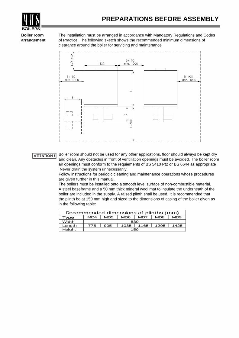
Boiler room The installation must be arranged in accordance with Mandatory Regulations and Codes arrangement of Practice. The following sketch shows the recommended minimum dimensions of
clearance around the bolier for servicing and maintenance
Boiler room should not be used for any other applications, floor should always be kept dry and clean. Any obstacles in front of ventillation openings must be avoided. The boiler room air openings must conform to the requiements of BS 5410 Pt2 or BS 6644 as appropriate Never drain the system unnecessarily.Follow instructions for periodic cleaning and maintenance operations whose procedures are given further in this manual.The boilers must be installed onto a smooth level surface of non-combustible material.A steel baseframe and a 50 mm thick mineral wool mat to insulate the underneath of the boiler are included in the supply. A raised plinth shall be used. It is recommended that the plinth be at 150 mm high and sized to the dimensions of casing of the boiler given asin the following table:
Water The system design must ensure a flow rate consistant with the output of the boiler atCirculation a temperature rise not normally exceeding 20ºC (25ºC Max).System Due to the Jetstream technology employed in the boiler, the boiler may be operated at
continuous low return water temperatures without condensation and without the need forback-end temperature protection measures, providing the minimum temperature limits detailed in the technical data are observed. This allows variable flow temperatures to be utilised (direct-on-boiler weather compensation) without the need for variable temperature mixing valves. This simplifies the installation and ensures peak operational efficiency fromthe boiler.Should the system be operated at temperatures below than those mentioned above, then a thermostatically controlled pumped by-pass (shunt pump) should installedbetween the flow and return pipes to raise the temperature of the return water.This is particularly important when firing with gas because of the higher dewpoint temperature of gas products of combustion.
Water levels should be checked regularly and any leakages corrected in order to keep system water make-up to a minimum, because excessive make-up will lead to scale deposits forming in the boiler waterways causing local overheating and damage to the boiler sections. Where there is doubt as to the quantity of water make-up, a water meter should be fitted. If a system is known to lose water continuously, or be heavilycontaminated with dirt or sludge, then consideration should be given to installing a plate type heat exchanger to separate the boiler from the damaging effects of the old system.
Boiler water systems should be thoroughly flushed and cleaned before a new boiler isinstalled and system water should be treated with a scale and corrosion inhibitorand best practise observed. The system should include strainers and consideration shouldbe given to fitting sludge traps if conditions warrant them.
The system can be either open vented or pressurised.The system must be fitted with appropriately sized safety relief valve, reference to BS5410 Part2 or BS6644 will give
Safety of guidance on selection.If the system is open vented then an appropriately sized open pipe water must be installed from the flow pipe adjacent to the boiler to run by the shortest possiblecirculation direct route to terminate over the feed and expansion cistern. The boiler flow and returnsystem pipes should be fitted with isolation valves taking care to ensure that the safety relief
valve is installed onto the flow pipe between the boiler flow connection and the flow isolation valve.An altitude guage should be installed onto the flow pipe at the same level as the top of of the boiler and marked with the minimum water level/pressure following first fillingof the system.
In the case of a sealed and pressurised heating system, an appropriately sized and charged expansion vessel should be installed in conjunction with an automaticwater make up unit (pressurisation unit).Filling the System . Non Domestic (other than in-house) fluid category 4For category 4 systems, the approved method of filling must comprise the followingcomponents arranged as shown: Control valve on the mains cold water pipework,Strainer,Verifiable backflow prevention device with Reduced Pressure Zone (RPZ valve)incorporating a type BA air gap, Tundish, Control valve on heating system.
PREPARATIONS BEFORE ASSEMBLY
Requirementson filling The quality of the filling and any refilling water is important and must be ofwater sufficient quality to maintain the following requirements:
pH 8 - 9.5Maximum hardness between 8 and 12 grammes of calcium carbonate per 100litres of water.
We strongly recommend that the system is chemically cleaned and thendosed with a good quality corrosion and scale inhibitor before the boiler isfirst fired. The boiler is guaranteed against material and manufacturing defectshowever, failures or problems brought about by inadequate water quality areexpressly excluded from any guarantee or warranty and will render the guarantee on the product void.
PREPARATIONS BEFORE ASSEMBLY
MD Jetstream MD boilers are delivered unassembled and consists of the following parts:Delivery Consignement
1. Boiler block: A block of sections, smokehood and front door is delivered on a pallet for easy shipping. The sections must be assembled in the boiler room. Refractories for combustion chamber insulation are mounted on the rear section at the factory. Smokehood is fixed to rear section. Boiler block contains the materials used in the assembly of the block such as nipples, fiberglass ropes, flow and return connections...
2. Casing/insulation box: This box contains all casings and baseframes (if required) together with the insulation blankets. Retarder sets and control panel are alsosupplied in this box.
Delivery method of Alpha Jetstream MD boilers.
ASSEMBLY INSTRUCTIONS
Assembly of Numbers in the brackets refer to position numbers in the exploded drawing.Boiler Body
1. Place steel profiles (19) which are usedas baseframes of the boiler parallel to each other as shown in the figure at the l/h side.The distance from the baseframes vary from 320 mm to 970 mm as the number of sections vary from 4 to 9.
2. Start assembly with rear section (1), clean all rope grooves on the section using a wire brush. Clean nipple ports and nipples using cloth and paraffin. Apply adhesive to the rope grooves on the front side of the section. Fix continuous lengths of 10 mm rope (5) in each groove starting with the outer groove as shown in following picture. Tape each end of rope. Apply jointing compound onto nipples, and place nipples (4) squarely in each nipple port and, using a wooden mallet, lightly tap nipple into the port to secure.
3. Take an intermediate section (2) and prepare the section as described above. Place rear section at the end of baseframes. With its unroped side facing towards the rear, fit the intermediate section squarely onto nipples of the rear section and secure by using a wooden mallet. Ensure that the rope on the rear section remains in correct position
NOTE: Do not fix rope into the grooves of the side of the intermediate section facing the rear section. Likewise, apply the same procedure for the following sections applying one rope between two sections.
4. Continue boiler assembly repeating the same procedures with the other sections. Apply "Compression Tools" passing them through bottom and top nipples as shown in following figure, and accordance with the table headed "Usage of Compression Tools", until the rope between each section is firm. The gap between each section should be 3-4 mm.
ASSEMBLY INSTRUCTIONS
320/450/580/710/840/970
Rear section
Intermediate section
Upper staybolt
Front section
Nipple
Copression tools
Usage of compression tools
Model Firstapplication(Number ofsections)
Secondapplication(Number ofsections)
MD4 4MD5 3 5MD6 3 6MD7 4 7MD8 4 8MD9 5 9
After assembly of all sections, apply compression tools for the block. Before loosening fit upper and lower staybolts (7,8) using M12 nuts (9) and washers (10).
5. Fit studs M12x45 (20) to return and flow connections of the rear section.
Do not use excessive force to tighten the nuts up on the staybolts, from 48 to 54 Nm (35 - 40 lbf/ft) torque is recommended.
Hydraulic test Fit plugs (147) to top and bottom of front section. Fit 1/8" plug (109) supplied in boiler block into 1/8" hole on top of the rear section (with control panel this hole is not used). For 1/2" and 3/8" instrument tappings on top of the rear section, use 1/2" and 3/8" pockets for bulbs supplied with standard control panel or suitable plugs. Use hydraulic test apparatus for the boiler. Fit bottom test flange with two globe valves and test gasket to return connection. Fit blank flange and the other test gasket to flow connection as shown for MD boiler in the following figure.
Connect a hydraulic test set to one of the globe valves on test flange fitted to return connection. Fill the boiler with water by connecting the other valve on test flange to the water circuit. Meanwhile, release the air left in the boiler via bulb pocket holes on top ofthe rear section. When water comes out of the holes, refit the bulb pockets . Turn the valve connected to circuit off and turn the other valve connected to the hydraulic test set on. Pressurise the boiler via the pump on the test set until the pressure gauge reaches the test pressure.
Hydrostatic test should be carried out at a pressure of 1.5 x P; where, P is themaximum operating pressure of boiler. Duration of test should be at least 30 minutes.
The hydrostatic test must always be carried out before boiler being jacketed or heat insulated, and connected to the heating circuit.
After hydrostatic test, "Boiler Assembly Certificate" should be filled in and signed by the erector/installer. In order for warranty terms of boiler to be valid, make surethat this certificate is completed, signed, and sent to MHS. We recommend that you ask for a copy of assembly certificate from erector/installer.
ASSEMBLY INSTRUCTIONS
6. Fit distribution pipe (22) with gasket (25) to return connection. Fit flanged stubpipes (21) and their gaskets (25) to flow and return connections. Fit nuts and washers to the 35 mm threaded end of M10x105 studs (145), screw and lock the studs into the corner positions of rear section.
When placing the distribution pipe into the return connection, ensure that the white arrowon the flange of the pipe points upwards (The axis of the pipe should be off -centre towards the bottom of the square flange). Wrong position of the distribution pipe will result in incorrect temperature gradient and higher condensation rate in the boiler.
ASSEMBLY INSTRUCTIONS
Jacket assembly
1. Fit cast iron hinges(143) used for carrying front door onto frontsection using 2 M8x30 setscrews (142) for each hinge.Before assembly of front door (131), first decide the side of hinging(for LH or RH opening). Screw hinge pins (141) into threaded holes.Screw a M16 nut (49) onto each hinge pin as shown in figure belowleft.
Hang the front door on M16 nuts. Position the front door up ordownwards by losening or tightening the M16 nuts.
2. There are two types of retarders. One is the second pass retarder (95) or (99) and the other is the third pass retarder (for 4,5,6,7 sections) (97). Second pass retarders consistof two stainless steel bladed modules (95 and 99). The modules are combined together according to following table for preparing second pass retarders. Retarders are placed into second and third flue gas passages of boiler as shown in following pictures:
In case of light or medium fuel-oil firing, the second pass retarders should not be used, and input to boiler should be slightly reduced to values given in technical informations.
3. Fix front door to front section using four x M10x30 setscrews(136) and 10.5 washers(137).
4. Loosen the nuts on the front end of the upper staybolts(8) and fit upper casing support (155) with its bend facing towards the rear section. After mounting the front support sheet, ensure it to be aligned parallel to the floor.
ASSEMBLY INSTRUCTIONS
Second pass retarder modules
MD4 MD5 MD6 MD7 MD8 MD9
2 bladed module 2 1 3 bladed module 1 2 2 2 2
5. Place boiler body insulation (117) squarely on top of boiler block. After placing theinsulation, secure both ends of the insulation blanket to lower staybolts by using fourretaining springs(156).
6. Fit left and right rear insulation panels(157) to smokehood (11) and secure by pushing onto the M10x105 studs (145). Fit base insulation panel (93) underneath the boiler block.
7. Fit side casings (148,149) passing M10x105 studs (145) through the holes on the return folds of the casing, hanging the front edges of casing onto the upper casing support (155) and fixing the front lower end of the casing to the free end of the lower staybolt (7). Fit side casings by M10 nuts (153) and washers (152) to the M10x105 studs (145), by M6 set screws to the front upper casing support and by M12 nuts and washers to the lower staybolts.
8. Fit the top casings (163,164) onto the side casings by special pins (162,161).
9. Fit the rear panel by self tapping screws (160) to the return folds of the side casings. The rear panel is in two parts - upper (158) and lower rear (159) panels.
ASSEMBLY INSTRUCTIONS
M10x105 studs
Insulation springs
Electrical 1. Before assembly of control panel on top casing front piece (163), pass the capillary Installation tubes of the panel through the large hole on the top casing. Fix control panel (110) onto
the top casing using 4 self tapping screws S 4.8x9.5
2. Place the bulbs of the control and safety thermostats into 1/2" pocket and the bulb ofboiler thermometer into 3/8" pocket fitted on the rear section routing all the capillarytubes underneath top casings but on the top side of the insulation blanket. Secure the bulbs of the instruments into the pockets with the clips supplied.
3. Fit top casing front panel mounted with the control panel onto the boiler.
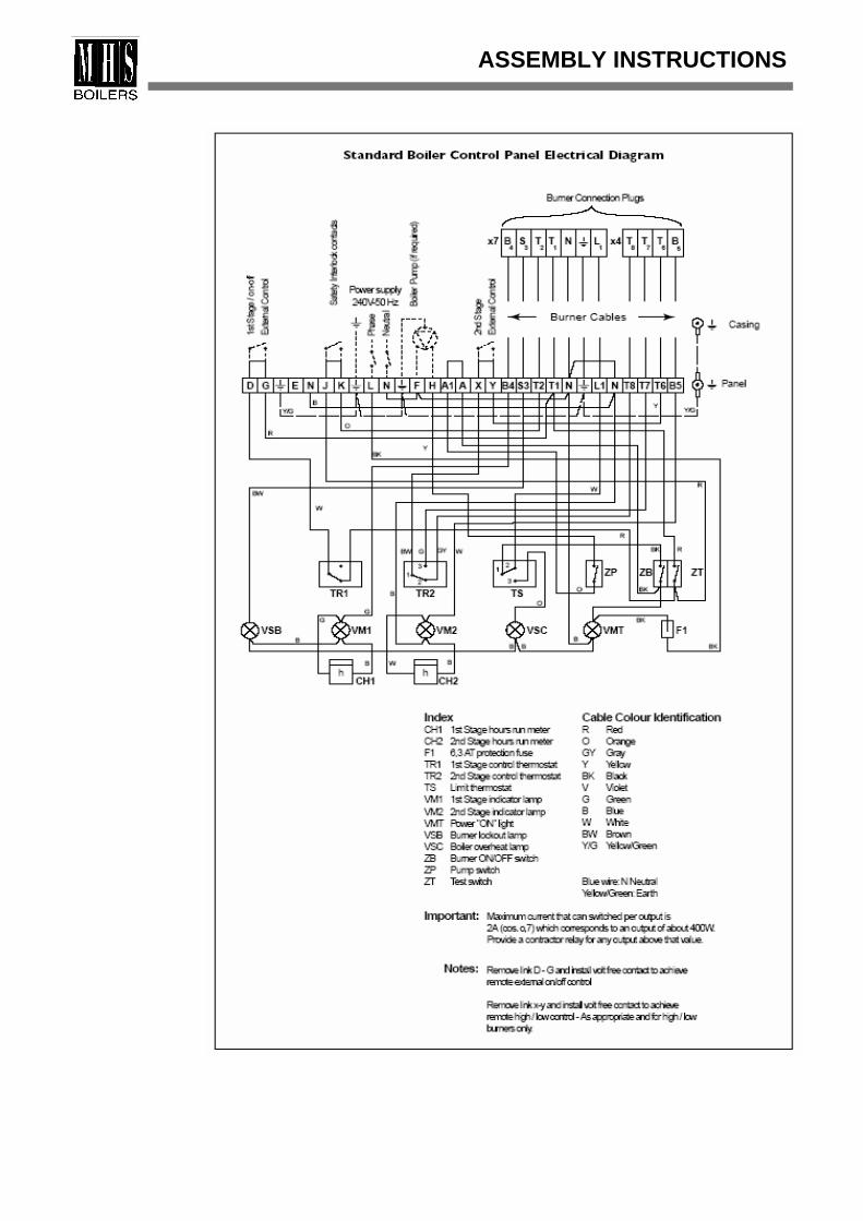
4. Pass electrical wiring through prepared hole in rear of side casing and route cables into control panel making sure that cables are on the top side of the insulation. Make electrical connections in accordance with Mandatory Regulations and Codes of Practice, and follow burner manufacturers instructions.
The main electrical supply should be taken from a local fused isolator having a minimum contact separation between the poles of 3 mm, and taken to the phase, neutral and earthconnection in the boiler control panel. The burner connection cables from the boiler control panel should be routed through the top and side panels, then shall pass under side panel to the burner, ensuring that the cables are placed on the outside of the boiler insulation blankets.
All cables should be suitable for a service temperature of 100 C and a load of 10 Amp, and have a minimum cross sectional area of 1,5 mm2.
This appliance must be earthed.
Control panel
Detail of the P3 climatic control panel can be found in the separate literature for this item.
ASSEMBLY INSTRUCTIONS
ASSEMBLY INSTRUCTIONS
Electrical safety Carry out the following electrical safety checks using a multimeter.checks
Earth continuity check1. Appliance must be electrically disconnected from the mains2. Set the meter to Ohmsx1 scale and zero if necessary3. Measure resistance between the earth connection point in the boiler control panel andthe earth connection point in the supply junction box or the earth pin on the 3 way plug if this is being used.4. If the resistance is greater than 0.1 Ohm, check all earth wires and connections forcontinuity and that they are clean and tight and rectify as necessary.
Short circuit check1. Appliance must be electrically disconnected from the mains and all appliance switchesset to "ON" including the thermostats.2. Set the meter to Ohmsx1 scale and measure the resistance between the neutral andphase terminals in the boiler control panel. If the meter monitors zero then there is a direct short cricuit and a fault that should be rectified.3. Set the meter to the Ohmsx100 scale, and measure the resistance between the phaseand earth block in the boiler control panel. If the meter monitors less than infinity then there is a fault that requires rectifying.
Resistance to earth check1. The appliance must be disconnected from the manis supply and all switches includingthe thermostats set to "ON".2. Set the meter to the Ohmsx100 scale3. Measure the resistance between the phase and the earth block. The reading should beinfinity and if there is any other reading then there is a fault which should be traced andrectified.
The Alpha Jetstream MD Boiler must only be commissioned and serviced by competantPre-firing checks persons of approved classes, qualified and certified to undertake the works involved.
i.e. Corgi/Oftec Registered.The following points must be checked before the operation of the boiler and system.1. Boiler seals, including front door, burner plate, rear cleaning cover, and flue / chimney connections.2. Electric supply, fuel and water system connections,water level, water quality and soundness of fuel supplies and correct purging of fuel supply pipework.3. Burner to ensure correct model and setting.4. Boiler controls, including thermostats.5. Sizing and settings of safety relief valves.6. Ventilation/air supply provision.
The burner is started by adjusting the first stage thermostat to desired water temperature. Firing With two stage, the first stage thermostat should be adjusted to a setting slightly higher
than that of the second stage thermostat. The adjustment of the fuel consumption of theburner and flue gas analysis should be carried out simultaneously to prevent the influences of the adjustments on each other. The flue gas analyser should sense from a distance at least four times the diameter of the flue to the flue outlet of the boiler to make a reliable analysis. Adjust the burner in accordance with the burner manufacturers instructions.The return temperatures to boiler due to fuel type fired should not be lower than the limits given in the following table to operate the boiler in non-condensing mode. These temperatures may decrease to lower points temporarily during the operation particularly during the initial starting period.
OPERATION
Fuel type
Lowest return temperatures
(oC) Natural gas, LPG 35 Light oil 25
Before carrying out any maintenance operations on the boiler, first of all turn off/isolateelectricity and oil or gas fuel supply valves.
Periodic 1. Cleaning of heat transfer surfaces of the boiler heat exchanger at a frequency determinedinspections by the usage patterns of the boiler but not exceeding 6 months for oil and 12 months for gas.
2. Controls settings 3. Ventilation provision4. Noise (excessive or unusual)5. Flue gas leakage (soot deposits / marks)6. Vibration (excessive or unusual)7. Fuel or water leakage8. Burner settings - check using flue gas analyser.9 .Effectiveness of the flue.10.Water quality/water treatment dosage
Cleaning Before starting to clean the boiler:
1. Isolate by switching off electrical supplies at the mains, and valve-off fuel supplies.2. Cover control panel and burner to protect from any damage.
To clean the boiler:
1. Disconnect fuel supplies from burner as necessary and open the front door (131)2. Remove all retarders inside the flue gas passages. Prepare the cleaning brush, combining items 101, and 102. Remove any deposits from combustion chamber and flue gas passages using cleaning brush.3. Clean the retarders and check their condition, replacing any that are damaged.4. Check the condition of the fiberglass braided rope (6) between front door and front section and replace if necessary 5. Re-fit all the retarders with their original positions, close the front door and check that it compresses squarely onto front section.6. Clean/remove any accumulated deposits from the smoke hood via the cleaning ports. For that operation, undo the rear cleaning cover (27) on the smokehood. Remove all deposits and check the condition of rear cleaning cover seals (28) and replace the seal if necessary. Re-fit cleaning cover.7. Check the condition of the fiberglass rope around the burner mounting plate and replace if necessary.8. Uncover the control panel and the burner. Clean/service the burner as necessary.9. Re-connect the boiler/burner to external supplies and check for soundness.10. Start the boiler and check for performance.11. It is recommended that a flue gas analysis be carried out to check the combustion.
MAINTENANCE AND CLEANING
To shut down Switch off the electrical supply and decrease the control thermostats on boiler control the boiler panel to the minimum set point. If switching off for an extended period e.g. Holidays, turn
off the gas or oil supplies at the service and isolating gas or oil valves on the burner.
Care of the 1. Do not shut down the boiler if freezing conditions are expected unless a frost protectionboiler thermostat has been incorporated into the control system.
2. Do not obstruct the airvents, grilles or other air openings in the boiler room, and ensurea clear path of combustion and ventillation air to the burner.3. Do not store objects on or near the burner, boiler, and flue.4. Do not use propellant sprays or chemicals particularly chlorine based chemicals in thevinicity of the boiler.5. The boiler must be serviced at regular intervals by competant persons.
To re-start 1. Check that the gas supply or oil isolating valve is open.the boiler 2. Switch on the electrical supply, set the control thermostats to the desired setting and
ensure any external controls (time/temperature controls) are turned on and calling for heat.3. The burner should now start pre-ventillation and then fire.
1. If there is fuel leakage from your boiler, first stop the system and shut down the oil valve at the outlet of the fuel tank. If a gas leak is suspected (e.g. Odour in the boiler room)
Fuel leakage do not use a naked flame to locate the leak, or turn on or off any electrical switches.Immediately contact your gas supplier, details should be on the notice at the gas meter.2. If there is leakage from an oil tank, it must be removed and replaced.
Electrical The boiler will not work, if the electricity is cut off. The boiler should start automatically failure when the electircity is restored.
Boiler If the burner does not operate; check that there is enough fuel in the tank, and the gate operational valve at the outlet of the tank is opened (oil fired installations). failures Ensure that any controls are calling for heat. Check/reset the burner lockout reset button.
Ensure that the system pumps are running and that the boiler overheat safety thermostatis not tripped (see "safety thermostat fault" below. If burner still fails to operate, seek expert assistance from your service company.
If the raditaors can not be heated; refer to followings:
System 1. There may be air in the circuit; it must be removed.heating problem 2. There may be pressure drop in the circuit. If the pressure gauge on the manometer of
the heating system is below the minimum safe value, water must be added to the circuit.3. The thermostat setpoint may be rather low; the setpoint degree must be increased.4. The room unit or programmable timer on the control panel may be in service. The adjustments of these devices must be checked again.
Safety In the case of safety thermostat lock-out; first check to make sure that the water level is thermostat correct. If there is any water loss from the system investigate and remedy, adding more fault water treatment as necessary. Reset the overheat safety themostat by pressing the reset
button under the removable cap. If the boiler should go to overheat safety lockout again or the thermostat fails to reset, then seek expert assistance from your service company.
Flue gas leakage 1. The leakage may be due to damaged/ineffective seals on the cleaning covers. from boiler 2. Check the condition of the fibreglass ropes between each section, also check the body seals between the front door and front section.
3. Check the effectiveness of the chimney and ensure no restrictions.
END-USER INSTRUCTIONS
EXPLODED DRAWINGS
MD JETSTREAM EXPLODED DRAWING(BOILER GROUP)
EXPLODED DRAWINGS
ALPHA JETSTREAM MD EXPLODED DRAWING(INSULATION AND OUTER CASINGS)
Form Nr. : MDT01
MODEL : BOILER GROUP NR.1 :RATED OUTPUT : BOILER GROUP NR.2 :FUEL TYPE : DATE OF MANUFACTURE :SERIAL NR. :
CONTACT PERSON :ADDRESS :
TELEPHONE :
COMPANY NAME :ADDRESS :
TELEPHONE :
COMPANY NAME :ADDRESS :
TELEPHONE :
Assembled ............ Boiler group tested at
Ps = 1. 5 x Pmax = 1.5 x ....... = .......... Bars
where Pmax is the maximum operating pressure of heating system;
for a duration of ……. minutes, and
No leakage detected
Leakages detected and corrected on following points:1.2.3.4.5.
OTHER FAULTS OR DEFICIENCIES DETECTED
TESTED BY: (Print Name)
DATE and SIGNATURE
EREC
TOR
HYD
RO
STA
TIC
TES
T D
ATA
CO
MM
ENTS
A COPY OF THIS TEST CERTIFICATE MUST BE RETURNED TO MHS BOILERS LTD
BOILER ASSEMBLY CERTIFICATE
BO
ILER
D
ATA
END
USE
RIN
STA
LLE
R
A member of the Modular Heating Group Plc35 Nobel Square, Burnt Mills Industrial Estate, Basildon, Essex, SS13 1LT. Tel: 01268 591010. Fax: 01268 728202