22
Installation and User's Manual for Modular Cuber Models C0322, C0522, C0330, C0530, C0630, C0830 and C1030

Installation and
User's Manual for
Modular Cuber
Models C0322, C0522, C0330, C0530,C0630, C0830 and C1030

Introduction
The design of this modular cuber is the result ofyears of experience and testing. Standard featuresinclude front accessible indicator lights and on-offswitches that provide the user with fast access tocritical information and easy operational control. .
Keep this manual for future reference.
This installation and user manual is divided intothree main sections: Installation, which providesthe trade person with the information needed to setup and install this product; Use and Operation,which provides the user with the information to usethe product; and Maintenance, which provides theuser with the information needed keep it operatingefficiently.
Note any Caution or Warning symbols when theyappear on the product or in this manual. Theyindicate potential hazards.
July 2006Page 1
C0322 through C1030Air and Water Cooled User Manual
Table of Contents
Installation: Product Specifications . . . . . . . . . . . . . . . . . . . . . . . . . . . . . . . Page 2
Model Number Description . . . . . . . . . . . . . . . . . . . . . . . . . . . . . . . . . . . Page 3
Product Description & Electrical Requirements . . . . . . . . . . . . . . . . . . . . . . . . . Page 4
C0322 and C0522 Cabinet Layout . . . . . . . . . . . . . . . . . . . . . . . . . . . . . . . Page 5
C0330, C0530, C0630, C0830 and C1030 Cabinet Layout . . . . . . . . . . . . . . . . . . . Page 6
Water . . . . . . . . . . . . . . . . . . . . . . . . . . . . . . . . . . . . . . . . . . . . . . Page 7
Panel Removal . . . . . . . . . . . . . . . . . . . . . . . . . . . . . . . . . . . . . . . . . Page 8
Plumbing Requirements . . . . . . . . . . . . . . . . . . . . . . . . . . . . . . . . . . . . . Page 9
Electrical . . . . . . . . . . . . . . . . . . . . . . . . . . . . . . . . . . . . . . . . . . . . . Page 10
Final Check List . . . . . . . . . . . . . . . . . . . . . . . . . . . . . . . . . . . . . . . . . Page 11
Initial Start Up . . . . . . . . . . . . . . . . . . . . . . . . . . . . . . . . . . . . . . . . . . Page 12
Adjustments . . . . . . . . . . . . . . . . . . . . . . . . . . . . . . . . . . . . . . . . . . . Page 13
Use and Operation. . . . . . . . . . . . . . . . . . . . . . . . . . . . . . . . . . . . . . . . Page 14
Control Switches. . . . . . . . . . . . . . . . . . . . . . . . . . . . . . . . . . . . . . . . . Page 15
Options . . . . . . . . . . . . . . . . . . . . . . . . . . . . . . . . . . . . . . . . . . . . . Page 16
Cleaning, Sanitation and Maintenance . . . . . . . . . . . . . . . . . . . . . . . . . . . . . Page 17
Air cooled condenser filter . . . . . . . . . . . . . . . . . . . . . . . . . . . . . . . . . . . . Page 19
What to do before calling for service . . . . . . . . . . . . . . . . . . . . . . . . . . . . . . Page 20

Installation: Product Specifications
Location Limitations:
The product is designed to be installed indoors, ina controlled environment. Air cooled modelsdischarge very warm air into the room out the back.Space must be allowed at the left side and back forair intake and discharge. Water cooled modelsdischarge warm water into the building’s drain.Space needs to be provided on both sides andabove for service access.
Space Limitations
Note: Although the machine will function, icecapacity of air cooled machines will be significantlyreduced with minimal clearance at the sides, backand top. Some space is recommended for serviceand maintenance purposes on all models.
6" of space at the sides and back are required foradequate operation. To get the most capacity,locate the machine away from heat producingappliances and heating ducts, and keep the leftside away from any wall, allow 12-18 inches ofspace for good air flow
Airflow is in the left side, out the back (as viewedfrom the front).
Environmental Limitations
Minimum Maximum
Airtemperature
50oF. 100
oF.
Watertemperature
40oF. 100
oF.
Waterpressure
20 psi 80 psi
Power supply – acceptable voltage ranges
Minimum Maximum
115 volt model 104 volts 126 volts
230 volt model 198 volts 253 volts
Warranty Information
The warranty statement for this product is providedseparately from this manual. Refer to it forapplicable coverage. In general warranty coversdefects in material or workmanship. It does notcover maintenance, corrections to installations, orsituations when the machine is operated incircumstances that exceed the limitations printedabove.
Product Information
The product is a modular cuber. That type ofmachine is designed to be placed on an icestorage bin or an ice dispenser. Many installationsonly require the matching bin, but some alsorequire an adapter to be placed between the binand the cuber or between the dispenser and thecuber. This product cannot be stacked. See thechart for application information.
May 2007Page 2
C0322 through C1030Air and Water Cooled User Manual
Air Flow

Model Number Description
Example:
• C0322SA-1A
• C= cuber
• 03= nominal ice capacity in 100s of pounds
• 22= nominal width of cabinet
• S= Cube size. S=small or half dice cube.M=medium or full dice cube
• A=Condenser type. A=air cooled. W=watercooled
• -1=115 60 Hz, -32=208-230 60 Hz
• A=Series revision code. A=first series
Note: Model numbers in the manual might includeonly the first five characters of the model number.
Options:
There are several field-installed options that can beinstalled at initial start up or later. They include:
• KVS, Vari-Smart Adjustable ice level system.
• KSB, SmartBoard Advanced feature board.
• KPMFA223, front air flow panel. Fits C0322and C0522.
• KPMFA303, front air flow panel. Fits C0330,C0530, C0630.
• KPFMA309, front air flow panel. Fits C0830and C1030.
• A39514-021 anti-recirculation baffle. FitsC0322, C0330, C0522, C0530, C0630.
• A39515-021, anti-recirculation baffle. FitsC0830 and C1030.
Some installations require bin or dispenser
adapters. See the table. Standard Bin
Applications - Adapter information.
ModelBH360,or B222or B322
B530P,B330P,B530S,HTB555orBH550
BH800,BH801,B842S
BH900,B948S
C0322,C0522
Direct fit KBT27Notavailable
Notavailable
C0530,C0630,C0830,C1030
Does notfit
Direct fit KBT28 KBT22
Hotel Dispensers
The HD22 and HD30 are compatible with this icemachine, no adapters are needed.
• HD22 – use with C0322 or C0522
• HD30 – use with C0330 or C0530
Note: All models ship with the On and Off switchesfront accessible. If desired, the On and Offswitches can be covered but by changing the bezelin the front panel’s trim strip. A cover-up bezelships loose with the machine.
Ice and Beverage Dispensers – Adapterinformation
Model ID150 ID200 or ID250
C0322, C0522 KBT42 KBT43
C0530, C0630,C0830, C1030
Does notfit
KBT44
Other Bins & Applications:
Note the drop zone and ultrasonic sensor locationsin the illustrations on the next pages.
Scotsman ice systems are designed andmanufactured with the highest regard for safetyand performance.
Scotsman assumes no liability of responsibility ofany kind for products manufactured by Scotsmanthat have been altered in any way, including theuse of any part and/or other components notspecifically approved by Scotsman.
Scotsman reserves the right to make designchanges and/or improvements at any time.Specifications and design are subject to changewithout notice.
August 2006Page 3
C0322 through C1030Air and Water Cooled User Manual

July 2006Page 4
C0322 through C1030Air and Water Cooled User Manual
Product Description & Electrical Requirements
Dimensions
w" x d" x h"Model
Electrical
volts/Hz/phaseCondenser
MinimumCircuitAmpacity
MaximumFuse Size*
22.75** x 24 x 23
C0322SA-1 115/60/1 Air 12.7 15
C0322SW-1 115/60/1 Water 11.9 15
C0322SA-32 208-230/60/1 Air 6.1 15
C0322SW-32 208-320/60/1 Water 5.6 15
C0522SA-1 115/60/1 Air 13.8 15
C0522SW-1 115/60/1 Water 12.2 15
C0522SA-32 208-230/60/1 Air 7.6 15
C0522SW-32 208-230/60/1 Water 6.7 15
30.75** x 24 x 23
C0330SA-1 115/60/1 Air 12.7 15
C0330SW-1 115/60/1 Water 11.9 15
C0330SA-32 208-230/60/1 Air 6.1 15
C0330SW-32 208-230/60/1 Water 5.6 15
C0530SA-1 115/60/1 Air 13.9 15
C0530SW-1 115/60/1 Water 12.2 15
C0530SA-32 208-230/60/1 Air 7.9 15
C0530SW-32 208-230/60/1 Water 6.7 15
C0630SA-32 208-230/60/1 Air 18.2 20
C0630SW-32 208-230/60/1 Water 17 20
30.75** x 24 x 29
C0830SA-32 208-230/60/1 Air 10.2 15
C0830SW-32 208-230/60/1 Water 9 15
C0830SA-3 208-230/60/3 Air 8.4 15
C0830SW-3 208-230/60/3 Water 7.2 15
C1030SA-32 208-230/60/1 Air 16 20
C1030SW-32 208-230/60/1 Water 14.8 15
C1030SA-3 208-230/60/3 Air 11 15
C1030SW-3 208-230/60/1 Water 9.8 15
Table notes: Medium cube models have the same electrical characteristics as Small. Series revisioncode omitted.
* Or HACR type circuit breakers.** Maximum width at top panel. Air cooled models add .75" for left side louvers.

C0322 and C0522 Cabinet Layout
July 2006Page 5
C0322 through C1030Air and Water Cooled User Manual
PLAN VIEW22" PRODIGY
24.00 REF.61
22.00 REF.55.9
2.005.12.00
5.1
19.0548.4
3.258.3
10.2526
7.0017.8
ICE DR
OP OP
ENING
ULTRASONICBIN LEVELSENSOR(OPTIONAL)
Top View
LEFT SIDE VIEW
24.0061
LOUVER ANDREMOVABLE FILTERAC UNITS ONLY
C0322, C0522 Air Cooled Side View
AIR COOLEDBACK VIEW 1.43
3.61.62
4.1
3.047.7
10.7927.4
14.5637
1.604.1
3/8" FPTWATERINLET
3/4" FPTDRAIN
.88" DIAELECTRICALACCESS
C0322, C0522 Air Cooled Back View
Note: Top number is centimeters, bottom number is inches.

AIR COOLEDBACK VIEW
3.067.8
10.8127.5
14.5937
1.483.7
1.734.4
1.704.3
3/4" FPTDRAIN
3/8" FPTWATERINLET
.88" DIAELECTRICALACCESS
C0330, C0530, C0630 AC Back View
LEFT SIDE VIEW24.00
61
LOUVER ANDREMOVABLE FILTERAC UNITS ONLY
C0830, C1030 Air Cooled Side View
C0330, C0530, C0630, C0830 and C1030 Cabinet Layout
July 2006Page 6
C0322 through C1030Air and Water Cooled User Manual
PLAN VIEW
24.00 REF.61
30.00 REF.76.2
2.005.12.00
5.1
19.0548.4
3.258.3
10.2526
7.0017.8
ICE DR
OP OP
ENING
ULTRASONICBIN LEVELSENSOR(OPTIONAL)
Top View - All
LEFT SIDE VIEW
24.0061
LOUVER ANDREMOVABLE FILTERAC UNITS ONLY
C0330, C0530, C0630 Air Cooled Side View
Note: Top number is centimeters, bottom number is inches.

Water
The quality of the water supplied to the ice machinewill have an impact on the time between cleaningsand ultimately on the life of the product. Water cancontain impurities either in suspension or insolution. Suspended solids can be filtered out. Insolution or dissolved solids cannot be filtered, theymust be diluted or treated. Water filters arerecommended to remove suspended solids. Somefilters have treatment in them for suspended solids.Check with a water treatment service for arecommendation.
RO water. This machine can be supplied withReverse Osmosis water, but the water conductivitymust be no less than 10 microSiemens/cm.
Potential for Airborne Contamination
Installing an ice machine near a source of yeast orsimilar material can result in the need for morefrequent sanitation cleanings due to the tendencyof these materials to contaminate the machine.Most water filters remove chlorine from the watersupply to the machine which contributes to thissituation. Testing has shown that using a filter thatdoes not remove chlorine, such as the ScotsmanAqua Patrol, will greatly improve this situation,while the ice making process itself will remove thechlorine from the ice, resulting in no taste or odorimpact. Additionally, devices intended to enhanceice machine sanitation, such as the ScotsmanAqua Bullet, can be placed in the machine to keepit cleaner between manual cleanings.
Water purge
Cube ice machines use more water than what endsup in the bin as ice. While most water is usedduring ice making, a portion is designed to bedrained out every cycle to reduce the amount ofhard water scale in the machine. That’s known aswater purge, and an effective purge can increasethe time between needed water system cleaning.
In addition, this product has the capability toautomatically vary the amount of water purgedbased on the purity of the water supplied to it. Thewater purge rate can also be set manually.Adjustments of purge due to local water conditionsare not covered by warranty.
August 2006Page 7
C0322 through C1030Air and Water Cooled User Manual
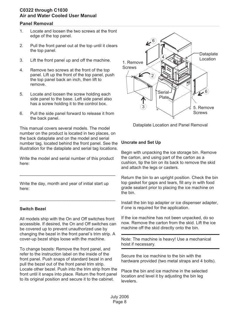
Panel Removal
1. Locate and loosen the two screws at the frontedge of the top panel.
2. Pull the front panel out at the top until it clearsthe top panel.
3. Lift the front panel up and off the machine.
4. Remove two screws at the front of the toppanel. Lift up the front of the top panel, pushthe top panel back an inch, then lift toremove.
5. Locate and loosen the screw holding eachside panel to the base. Left side panel alsohas a screw holding it to the control box.
6. Pull the side panel forward to release it fromthe back panel.
This manual covers several models. The modelnumber on the product is located in two places, onthe back dataplate and on the model and serialnumber tag, located behind the front panel. See theillustration for the dataplate and serial tag locations.
Write the model and serial number of this producthere:
________________________________________
Write the day, month and year of initial start uphere:
________________________________________
Switch Bezel
All models ship with the On and Off switches frontaccessible. If desired, the On and Off switches canbe covered up to prevent unauthorized use bychanging the bezel in the front panel’s trim strip. Acover-up bezel ships loose with the machine.
To change bezels: Remove the front panel, andrefer to the instruction label on the inside of thefront panel. Push snaps of standard bezel in andpull the bezel out of the front panel trim strip.Locate other bezel. Push into the trim strip from thefront until it snaps into place. Return the front panelto its original position and secure it to the cabinet.
Uncrate and Set Up
Begin with unpacking the ice storage bin. Removethe carton, and using part of the carton as acushion, tip the bin on its back to remove the skidand attach the legs or casters.
Return the bin to an upright position. Check the bintop gasket for gaps and tears, fill any in with foodgrade sealant prior to placing the ice machine onthe bin.
Install the bin top adapter or ice dispenser adapter,if one is required for the application.
If the ice machine has not been unpacked, do sonow. Remove the carton from the skid. Lift the icemachine off the skid directly onto the bin.
Note: The machine is heavy! Use a mechanicalhoist if necessary.
Secure the ice machine to the bin with thehardware provided (two metal straps and 4 bolts).
Place the bin and ice machine in the selectedlocation and level it by adjusting the bin leglevelers.
July 2006Page 8
C0322 through C1030Air and Water Cooled User Manual
Dataplate Location and Panel Removal
6
1. RemoveScrews
2
5. RemoveScrews
3
4
6
DataplateLocation
SerialPlate

Plumbing Requirements
All models require connection to cold, potablewater. A hand actuated valve within site of themachine is required. Air cooled models have asingle 3/8” FPT inlet water connection; a 3/8” FPTto 3/8” male flare adapter is supplied with themachine and can be used if desired.
Water cooled models have a 1/2" FPT drain fittingplus an additional 3/8” FPT condenser inlet waterconnection.
Water Filters
If connecting to water filtration, filter only the waterto the reservoir, not to the condenser. Install a newcartridge if the filters were used with a priormachine.
All models require drain tubing to be attached tothem. Air cooled models have a single ¾” FPTdrain fitting in the back of the cabinet. Water cooledmodels have the same fitting plus an additional ½”FPT drain fitting in the back of the cabinet.
Install new tubing when replacing a prior icemachine, as the tubing will have been sized for theold model and might not be correct for this one.
1. Connect water supply to water inlet fittings.3/8" OD tubing is recommended.
Note: This NSF listed model has a 1" anti-back flowair gap between the water inlet tube end and thehighest possible reservoir water level, no back flowdevice is required for the potable water inlet.
2. Connect drain tubing to drain fittings.
3. Route the drain tubing to building drain. Followlocal codes for air gap.
Drain Tubing:
Use rigid drain tubes and route them separately –
do not Tee into the bin’s drain and, if water cooled,
do not Tee the condenser drain into the reservoiror bin drain.
Vent the reservoir drain. A vertical vent at the backof the drain, extended about 8 - 10" will allow thegravity drain to empty and also keep any surgesduring draining from discharging water out thevent..
Horizontal runs of drain tubing need a ¼” fall perfoot of run for proper draining.
Follow all applicable codes.
August 2006Page 9
C0322 through C1030Air and Water Cooled User Manual
Water Fitting
Plumbing Connections
Floor Drain
WaterSupply
Water CooledSupply
Water Cooled Shown, Air Cooled Similar
WaterCooledDrain
Bin DrainConnection
ReservoirDrain
Connection
Drain Vent
PotableWater
Connection
Inlet WaterConnection

Electrical
The machine is not supplied with a power cord, onemust either be field installed or the machinehard-wired.
The dataplate on the back of the cabinet details thepower requirements, including voltage, phase,minimum circuit ampacity and maximum fuse size.HACR type circuit breakers may be used in placeof fuses. Extension cords are not permitted. Use ofa licensed electrician is recommended.
Electrical connections are made inside the junctionbox in the back panel of the ice machine.
1. Remove the junction box cover and route thepower cord through the access hole andproperly attach the power supply wires to theleads in the junction box.
2. Install a field supplied strain relief per code.Attach a ground wire to the ground connectionin the junction box.
3. Check voltage when complete.
4. Return the junction box cover to its originalposition and secure with the original screws.
The electrical disconnect switch with fuseprotection must be a two pole type with a minimumof 3 mm between open contacts.
Follow all applicable local, state and national
codes.
July 2006Page 10
C0322 through C1030Air and Water Cooled User Manual
Ground WireConnection
InstallStrainRelief
PowerSupplyWires
JunctionBoxCover
Electrical Connections, Back of Unit

Final Check List
After connections,
1. Wash out the bin. If desired, the interior of thebin could be sanitized.
2. Locate the ice scoop (if supplied) and have itavailable for use when needed.
Final Check List:
1. Is the unit located indoors in a controlledenvironment?
2. Is the unit located where it can receiveadequate cooling air?
3. Has the correct electrical power been suppliedto the machine?
4. Have all the water supply connections beenmade?
5. Have all the drain connections been made?
6. Has the unit been leveled?
7. Have all unpacking materials and tape beenremoved?
8. Is the correct switch bezel installed in the trimstrip?
9. Is the water pressure adequate?
10. Have the drain connections been checked forleaks?
11. Has the bin interior been wiped clean orsanitized?
12. Have any water filter cartridges been replaced?
13. Have all required kits and adapters beenproperly installed?
July 2006Page 11
C0322 through C1030Air and Water Cooled User Manual

Initial Start Up
1. Remove front panel. Check machine for anypacking or wires rubbing moving parts. Notelocation of control board in upper left corner ofthe machine’s front.
2. Remove tape securing curtain to evaporator.
3. Switch on the electrical power to the machine.Observe that some of the control’s indicatorlights glow and its display shows O.
4. Open the water supply valve.
5. Push and release the ON button. The codedisplay will begin to blink F.
The purge valve opens, the water pump starts andthe inlet water valve opens to add water to thereservoir. In a few seconds the purge valve closesand the water pump stops. Water will flow into themachine until the reservoir is full. The hot gas valveand harvest assist device will activate, then thecompressor and water pump will start. If it’s an aircooled model the fan(s) motors will begin to turn afew moments after the compressor starts. Thedisplay will show a continuous F. Five seconds laterthe hot gas valve will close and the harvest assistdevice will return to its standby position. Warm airwill be discharged from air cooled models.
6. Observe the Ready for Harvest indicator light.It may blink early in the cycle, that is normal.The control will ignore that signal for the first 6minutes of freeze.
7. During the Freeze cycle move the curtain andobserve that the SW1 or SW2 light on thecontrol board blinks On when the curtainmoves away from the evaporator and Off whenreturned to its normal position.
Note: Moving the curtain during the Freeze cyclehas no affect on control function, but will causewater to flow into the cube chute.
8. When enough ice has frozen, the Ready forHarvest indicator light will be on steady. Afterit’s been on steady for a few seconds Harvestwill begin.
The display shows an H. The hot gas valve opens,the air cooled fan motor(s) shut off and the harvestassist mechanism is activated. The purge valveopens to drain some water, when it does the inletwater valve opens to refill the reservoir. After a few
seconds the purge valve closes but the inlet watervalve continues to fill the reservoir. Harvestcontinues until the ice is released as a unit andforces the curtain to open. When the curtain opensit signals the controller which returns the unit to afreeze cycle.
9. Check the ice harvested for proper bridgethickness. The ice bridge is factory set at 1/8inch. If needed, adjust bridge thickness. DoNOT make it too thin.
10. Return the front panel to its normal positionand secure it to the machine.
11. Instruct the user in the operation of themachine and its maintenance requirements.
12. Fill out and mail the warranty registration form.
Typical Ice Making Cycle Times (minutes).
Listed times are for clean machines in properinstallations. Cycle length at startup will be longeruntil the system stabilizes.
Model70
oF air /
50oF. water
90oF. air /
70oF. water
C0322A 10-12 14-16
C0322W 9-11 10-12
C0522A 11-13 16-18
C0522W 13-15 13-15
C0330A 9-11 12-14
C0330W 8-10 9-11
C0530A 12-14 16-18
C0530W 10-12 11-13
C0630A 9-11 11-13
C0630W 7-9 10-12
C0830A 10-12 13-15
C0830W 11-13 12-14
C1030A 9-11 11-13
C1030W 9-11 10-12
July 2006Page 12
C0322 through C1030Air and Water Cooled User Manual
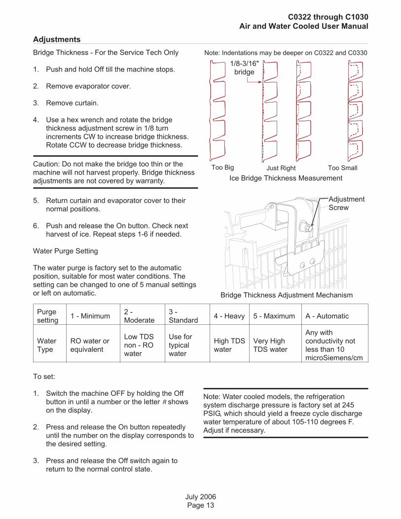
Adjustments
Bridge Thickness - For the Service Tech Only
1. Push and hold Off till the machine stops.
2. Remove evaporator cover.
3. Remove curtain.
4. Use a hex wrench and rotate the bridgethickness adjustment screw in 1/8 turnincrements CW to increase bridge thickness.Rotate CCW to decrease bridge thickness.
Caution: Do not make the bridge too thin or themachine will not harvest properly. Bridge thicknessadjustments are not covered by warranty.
5. Return curtain and evaporator cover to theirnormal positions.
6. Push and release the On button. Check nextharvest of ice. Repeat steps 1-6 if needed.
Water Purge Setting
The water purge is factory set to the automaticposition, suitable for most water conditions. Thesetting can be changed to one of 5 manual settingsor left on automatic.
Purgesetting
1 - Minimum2 -Moderate
3 -Standard
4 - Heavy 5 - Maximum A - Automatic
WaterType
RO water orequivalent
Low TDSnon - ROwater
Use fortypicalwater
High TDSwater
Very HighTDS water
Any withconductivity notless than 10microSiemens/cm
To set:
1. Switch the machine OFF by holding the Offbutton in until a number or the letter A showson the display.
2. Press and release the On button repeatedlyuntil the number on the display corresponds tothe desired setting.
3. Press and release the Off switch again toreturn to the normal control state.
July 2006Page 13
C0322 through C1030Air and Water Cooled User Manual
Bridge Thickness Adjustment Mechanism
Ice Bridge Thickness Measurement
AdjustmentScrew
Note: Indentations may be deeper on C0322 and C0330
Too Big Too SmallJust Right
Note: Water cooled models, the refrigerationsystem discharge pressure is factory set at 245PSIG, which should yield a freeze cycle dischargewater temperature of about 105-110 degrees F.Adjust if necessary.
1/8-3/16"bridge

Use and Operation
Once started, the ice machine will automaticallymake ice until the bin or dispenser is full of ice.When ice level drops, the ice machine will resumemaking ice.
Caution: Do not place anything on top of the icemachine, including the ice scoop. Debris andmoisture from objects on top of the machine canwork their way into the cabinet and cause seriousdamage. Damage caused by foreign material is notcovered by warranty.
There are four indicator lights at the front of themachine that provide information on the conditionof the machine.
Indicator Lights:
• Power
• Status
• Water
• De-scale & Sanitize
Indicator Lights & Their Meanings
Power Status Water De-Scale & Sanitize
Steady Green Normal Normal – bin full or making ice - -
Blinking GreenSelf TestFailure
Switching on or off - -
Blinking Red -Diagnostic shutdown or, if makingice, temperature sensor failure
Lack ofwater
-
Yellow - - -Time to de-scale andsanitize
BlinkingYellow
- - - In Cleaning mode
Light off No power Switched off Normal Normal
All Blinking Unit remotely locked out – check with leasing company
If the Water light is on, the machine has sensed alack of water. Check the water supply to themachine. The water could have been shut off or thewater filter cartridges might need to be changed.
If the De-Scale light is on, the machine hasdetermined that it needs to be cleaned. Contact anauthorized Scotsman service agent and have themachine cleaned, de-scaled and sanitized.
July 2006Page 14
C0322 through C1030Air and Water Cooled User Manual
Note: A Component Indicator Light switches ON toindicate that the component is operating.
Note: There are two Curtain Switch lights, SW1 andSW2. These single plate models have one curtainswitch light on all the time, as a curtain switch lightis ON when a curtain is either open or not present.
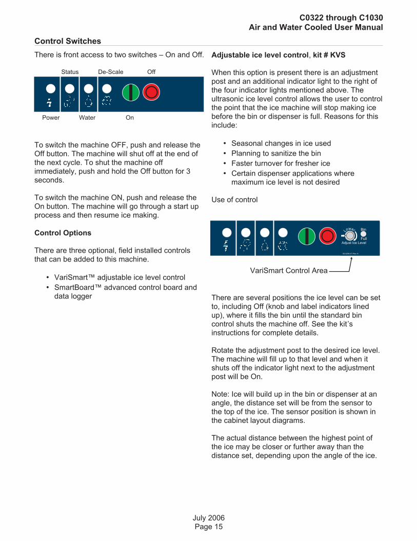
Control Switches
There is front access to two switches – On and Off.
To switch the machine OFF, push and release theOff button. The machine will shut off at the end ofthe next cycle. To shut the machine offimmediately, push and hold the Off button for 3seconds.
To switch the machine ON, push and release theOn button. The machine will go through a start upprocess and then resume ice making.
Control Options
There are three optional, field installed controlsthat can be added to this machine.
• VariSmart™ adjustable ice level control
• SmartBoard™ advanced control board anddata logger
Adjustable ice level control, kit # KVS
When this option is present there is an adjustmentpost and an additional indicator light to the right ofthe four indicator lights mentioned above. Theultrasonic ice level control allows the user to controlthe point that the ice machine will stop making icebefore the bin or dispenser is full. Reasons for thisinclude:
• Seasonal changes in ice used
• Planning to sanitize the bin
• Faster turnover for fresher ice
• Certain dispenser applications wheremaximum ice level is not desired
Use of control
There are several positions the ice level can be setto, including Off (knob and label indicators linedup), where it fills the bin until the standard bincontrol shuts the machine off. See the kit’sinstructions for complete details.
Rotate the adjustment post to the desired ice level.The machine will fill up to that level and when itshuts off the indicator light next to the adjustmentpost will be On.
Note: Ice will build up in the bin or dispenser at anangle, the distance set will be from the sensor tothe top of the ice. The sensor position is shown inthe cabinet layout diagrams.
The actual distance between the highest point ofthe ice may be closer or further away than thedistance set, depending upon the angle of the ice.
July 2006Page 15
C0322 through C1030Air and Water Cooled User Manual
Power Water On
Status De-Scale Off
02-4294-01 Rev. A.
Adjust Ice Level
Lower Bin
Full
VariSmart Control Area

Options
Advanced Feature Board, kit #KSB
When this option is present there is an additionaldisplay panel in the area below the main controlboard. It is not visible when the front panel is on.The Smart-Board’s features include:
• Seven day programmable ice level settingwhen used with the optional Ultrasonic icelevel control
• Recording of machine operation, includingcycle time.
• Calculation of average cycle time
• Recall of malfunctions with the time theyoccurred.
Ice
The cuber drops ice in large sections. That ice willbreak up into random parts as it falls into the bin,but some large sections may remain on top of theice in the bin. When removing ice, tap the groups ofice with an ice scoop to separate them into smallerunits. In a dispenser, this ice will break up intomostly individual cubes as the dispensemechanism moves the ice.
The ice in the bin will slope down from the right tothe left. This is normal.
Heat
Air cooled models will generate heat when inoperation. That heat is discharged out the back ofthe cabinet.
Noise
The ice machine will make noise when it is in icemaking mode. The compressor, fan motor(s) if aircooled and water pump all produce some sound. Itis also normal to hear some cracking just beforethe harvest cycle begins. In addition, during theharvest cycle the harvest assist solenoid will clicktwice as it pushes the ice out and returns to itsnormal position. The ice harvests as a unit or slab,which makes some noise when it impacts the bin ordispenser. These noises are all normal for thismachine.
July 2006Page 16
C0322 through C1030Air and Water Cooled User Manual
SmartBoard Advanced Feature Control™
See Instructions for Available Features
34SEL
02-4293-01 Rev A.
ENTER
ESC

Cleaning, Sanitation and Maintenance
This ice system requires three types ofmaintenance:
• Remove the build up of mineral scale from the ice machine’s water system and sensors.
• Sanitize the ice machine’s water system and the ice storage bin or dispenser.
• Clean or replace the air filter and clean the air cooled condenser (air cooled models only).
It is the User’s responsibility to keep the ice machine and ice storage bin in a sanitary condition. Withouthuman intervention, sanitation will not be maintained. Ice machines also require occasional cleaning oftheir water systems with a specifically designed chemical. This chemical dissolves mineral build up thatforms during the ice making process.
Sanitize the ice storage bin as frequently as local health codes require, and every time the ice machineis cleaned and sanitized.
The ice machine’s water system should be cleaned and sanitized a minimum of twice per year.
1. Remove the front panel.
2. Remove the evaporator cover.
3. If the machine is operating, push and releasethe Harvest button. When the machinecompletes the Harvest cycle it will stop. If thebin is full (b shows in display) push and releasethe Off button.
4. Remove all ice from the storage bin ordispenser.
5. Push and release the Clean button. The yellowClean light will blink and the display will showC. The machine will drain the reservoir and refillit. Go onto the next step when the reservoir hasfilled.
6. Pour 8 ounces of Scotsman Clear 1 icemachine scale remover into the reservoir.
7. Allow the ice machine scale remover tocirculate in the water system for at least 10minutes.
8. Push and release the Clean button again. Theyellow Clean light will be on continuously andthe machine will drain and refill the reservoirrepeatedly to purge out the ice machine scaleremover and residue.
9. Allow the drain and refill process to continue forat least 20 minutes.
10. Push and release the Off button. The cleancycle will stop and the display will show O.
Note: If unit has not been de-scaled for anextended period of time and significant mineralscale remains, repeat steps 5-10.
11. Mix a cleaning solution of 1 oz of ice machinescale remover to 12 ounces of water.
12. Locate curtain, push in on edge of curtain bypivot pin to release it. Pull curtain out ofmachine.
July 2006Page 17
C0322 through C1030Air and Water Cooled User Manual
Ice machine cleaner containsacids. Acids can cause burns.If concentrated cleanercomes in contact with skin,flush with water. If swallowed,do NOT induce vomiting.Give large amounts of wateror milk. Call Physicianimmediately. Keep out of thereach of children.
Pull Here
Push Here

13. Remove water distributor from ice machine.Inspect distributor for restricted orifice holes.Be sure all holes are fully open.
14. Locate ice thickness sensor. Squeezemounting legs together to release sensor.Wash the metal surfaces of the sensor and theadjustment screw with ice machine scaleremover solution. Also wash the waterdistributor and curtain with the ice machinecleaner solution.
15. Locate water level sensor. Squeeze catchestogether and pull up to remove sensor. Washmetal surfaces of sensor with ice machinescale remover solution.
16. Mix a solution of sanitizer.
Note: A possible sanitizing solution may be madeby mixing 1 ounce of liquid household bleach with 2gallons of warm (95-115
oF.) potable water.
17. Thoroughly wash all surfaces of the icethickness sensor, water level sensor, curtainand water distributor with the sanitizer solution.
18. Wash all interior surfaces of the freezingcompartment, including evaporator cover andright side panel liner with the sanitizer solution.
19. Return water level sensor, ice thicknesssensor, water distributor and curtain to theirnormal positions.
20. Push and hold the clean button to drain thereservoir. Push and release the clean buttonagain and when the purge valve indicator lightgoes out, immediately pour the remainingcleaning solution into the reservoir.
21. Circulate the sanitizer solution for 10 minutes,then push and release the Clean button.
22. Allow the water system to be flushed ofsanitizer for at least 20 minutes, then push andrelease the Off button.
23. Return the evaporator cover and front panel totheir normal position and secure with theoriginal fasteners.
24. Push and release the On button to resume icemaking.
Ice Storage Bin
1. Remove and discard all ice.
2. Mix a solution of 7 ounces of Scotsman Clear 1ice machine scale remover in 84 ounces ofpotable water and wash all interior surfaces ofthe ice storage bin to remove any mineral scalebuild up. Pour excess cleaner solution into thebin’s drain.
3. Mix a solution of sanitizer and thoroughly washall interior surfaces of the ice storage bin. Pourexcess sanitizer solution into the bin’s drain.
July 2006Page 18
C0322 through C1030Air and Water Cooled User Manual
Remove Water Distributor
Squeeze Tabs Together, Slide Out Until it Stops,Then Lift to Remove
Inspect Orifice Holes
Inspect Water Distributor
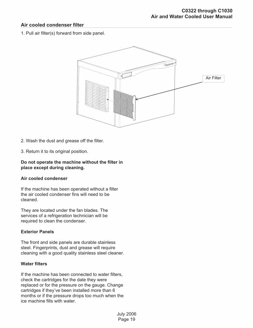
Air cooled condenser filter
1. Pull air filter(s) forward from side panel.
2. Wash the dust and grease off the filter.
3. Return it to its original position.
Do not operate the machine without the filter in
place except during cleaning.
Air cooled condenser
If the machine has been operated without a filterthe air cooled condenser fins will need to becleaned.
They are located under the fan blades. Theservices of a refrigeration technician will berequired to clean the condenser.
Exterior Panels
The front and side panels are durable stainlesssteel. Fingerprints, dust and grease will requirecleaning with a good quality stainless steel cleaner.
Water filters
If the machine has been connected to water filters,check the cartridges for the date they werereplaced or for the pressure on the gauge. Changecartridges if they’ve been installed more than 6months or if the pressure drops too much when theice machine fills with water.
July 2006Page 19
C0322 through C1030Air and Water Cooled User Manual
Air Filter

What to do before calling for service
Reasons the machine might shut itself off:
• Lack of water.
• Freeze cycle takes too long.
• Harvest cycle takes too long.
• High discharge temperature.
• Controller self test failure.
Check the following:
1. Has the water supply to the ice machine orbuilding been shut off? If yes, the ice machine willautomatically restart within 25 minutes after waterbegins to flow to it.
2. Has power been shut off to the ice machine? Ifyes, the ice machine will automatically restart whenpower is restored.
3. Has someone shut the water off to a watercooled unit? If yes, after the water supply has beenrestored the ice machine may need to be manuallyreset.
4. Is the curtain open because some ice is stuckunder it? If so, remove the ice and the machineshould start in a few minutes.
Note: Curtain can be removed & replaced anytimethe machine is in a standby mode or when it is in afreeze cycle. However, removal of the curtainduring freeze will result in water flowing into thebin. Removal of the curtain during harvestterminates harvest at that point and, if left off, willresult in the machine shutting off.
To Manually Reset the machine.
• Push and release the Off button.
• Push and release the On button.
To Shut the Machine Off:
1. Push and hold the Off button for 3 seconds oruntil the machine stops.
July 2006Page 20
C0322 through C1030Air and Water Cooled User Manual
Reset or Switch Off
Clear ice From Beneath Curtain
Clear IceFrom Here
Curtain

SCOTSMAN ICE SYSTEMS
775 Corporate Woods Parkway, Vernon Hills, IL 60061
800-533-6006
www.scotsman-ice.com
17-3083-01


