American Truckboxes, LLC., Installation Manual Web Page: www.truckbox.com 2018 American Truckboxes, LLC. Made in USA Page 1 Welcome to American Truckboxes, LLC®, Manufacturers of Installation Catalog Quality Built Tool Boxes WWW.TRUCKBOX.COM
Transcript
American Truckboxes, LLC., Installation Manual
Web Page: www.truckbox.com 2018 American Truckboxes, LLC. Made in USA Page 1
Welcome to American Truckboxes, LLC®, Manufacturers of
Installation
Catalog
Quality Built Tool Boxes
WWW.TRUCKBOX.COM
American Truckboxes, LLC., Installation Manual
Web Page: www.truckbox.com 2018 American Truckboxes, LLC. Made in USA Page 2
8. Under Deck Underbody Mount 10 19. L-Shape Mounting Brackets 22-26
9. Drawer Utility Boxes 11 20. Top Mount Brackets 27
10. Top Side Utility Boxes 12 21. BLB Bumper 28
11. Chest Boxes 13 22. Warranty & Special Notice 29
12. A-Frame Boxes 14 23.
Caution and Please Read Carefully Attention: Read and understand all instruction and warnings before installing and operating or using ATB product. Mounting box properly is
always very important. If done correctly, it will add longer life to your box. Always try to fasten box or brackets as parallel as possible, mount
box as high from the ground as possible.
Danger: Do not use ATB products for transporting or storing flammables, explosives, hazardous material, or hazardous waste, such as
containers of propane, gasoline, solvents, gun powder and acetylene. ATB products are designed and safe for use in storing and transporting
tools, equipment, and similar material. Any modification made to ATB products, or unintended use of ATB products, can or could create a
hazardous condition that can cause death, serious personal injury, or property damage.
Warning: Before mounting ATB products, use extra precautions on placement. ATB products can reduce driver's ability to clearly see
roadways, vehicular and pedestrian traffic, and other objects through the rear and side windows and mirrors of the vehicle. Make all
adjustments necessary to ensure maximum visibility. State and local laws may prohibit obstruction of windows in a moving vehicle.
Note: Before drilling, make sure all electrical wiring and components, fuel tank and associated components are not in the drilling
pattern.
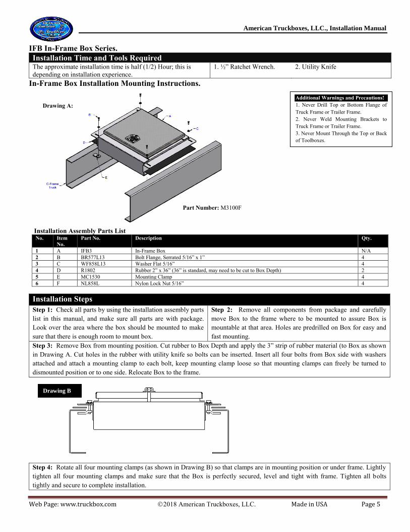
Warning and Precautions!
A. Never Drill Top or Bottom Flange of Truck Frame or Trailer Frame.
B. Never Weld Mounting Brackets to Truck Frame or Trailer Frame.
C. Never Mount Through the Top of any Box.
Maintaining & Caring For Your Box.
1. Lubricate hinges and all moving lock parts periodically with
light household oil.
2. Check and tighten bolts periodically.
3. Check and replace worn-out weather stripping as needed.
4. Check and replace worn-out gas springs.
Notice
2. The Manufacturer has the right to make changes in
material and design at any time without notice.
3. Product design and fit are based on vehicle design
available at the revision date. Check product design or
contact your representative, distributor or American
Truckboxes, LLC to verify fitting of product design.
Web Page: www.truckbox.com 2018 American Truckboxes, LLC. Made in USA Page 3
SB10 Step Box Series.
Installation Time and Tools Required The approximate installation time is one (1.5) Hours; this is depending on installation experience.
1. ¾” Ratchet Wrench. 2. ¾” Wrench
3. Tape Measure
4. Drill & 9/16” or 11/16” Bit 5. Utility Knife
6. Blocks
Step Box Installation Mounting Instructions:
M3000H Installation Assembly Parts List
M3000C Installation Assembly Parts List
No. Item No. Part No. Description Qty.
No. Item No. Part No. Description Qty.
1 A SB10 Step Box N/A
1 A SB10 Step Box N/A
2 B MC1258 Hook ½” x 5/8” Stud” (Grade 8) 4
2 B BH858R17 Bolt ½” x 2” (Grade 8) 4
3 C WF858V16 Washer Flat 5/8” 4
3 C WF858R15 Washer Flat ½” 4
4 D R1803 Rubber 3” x 12” 2
4 D R1803 Rubber 3” x 12” 2
5 E NL858V Nut Lock 5/8” 4
5 E NL858R Nut Lock ½” 4
Installation Steps
Step 1: Check all parts by using the installation assembly parts list in this manual,
and make sure all parts are with package. Look over the area where the box should
be mounted to make sure that there is enough room to mount box.
Step 2: Remove all components from package and carefully move Box to
the frame where to be mounted to assure Box is mountable at that area. Holes
are not predrilled in Box due to variety of different hole patterns.
Step 3: Remove Box from mounting position. Drill four holes in back of Box as shown in drawings below (11/16” diameter for Figure 1 and 9/16” diameter for
Figure 2).
Internal MountingBrackets
Truck Frame Rail
Rear View of Step Box(Figure 2)
A
158"
158"
138" To Center
Hole
138" To Center
Hole
A
Top Step
M3000C Mounting Kit
Internal MountingBrackets
Truck Frame Rail
Rear View of Step Box(Figure 1)
158"
158"
138" To Center
Hole
138" To Center
Hole
Top Step
M3000H Mounting Kit
AA B
B
C
C
C = Box Width Minus 2-3/4"
CalculationsA = B Minus 3-1/4"
C = Box Width Minus 2-3/4"
Calculations
A = B Plus a 3/4"
Step 4: Relocate Box back to mounting position. For M3000H Kit, go
to step No. 6.
Step 5: Mark the predrilled holes, patterned on the Box you just drilled
to the frame where holes need to be drilled. Remove Box and drill four
9/16” diameter holes at each mark on the frame (refer to truck O.E.M.
shop manual for recommended frame drilling instructions).
Step 6: Apply the 3” strip of rubber material (d) to Box (as shown in
Drawing A or B). Cut drilled holes in the rubber you just applied, with
a utility knife and relocate Box to the frame. Insert Hooks or Bolts with
washers, through the holes (as shown on Drawing A or B). Place one
flat washer under a lock nut and tighten all nuts securely to complete
installation.
Drawing A:
Part Number: M3000H
Drawing B:
Part Number: M3000C
Note: This Step Box is designed with
internal mounting brackets; no
external brackets are required
providing the cargo weight will not
exceed 150 lbs.
Use M2000 or M2100 L-Shape
Mounting Brackets for Cargo
Weight over 150lbs.
Note. If spacing is required due
to bolts or brackets on truck
frame place an aluminum spacer
between box and truck frame and
longer bolts will need to be used.
Warning and Precautions! Never Drill Top or Bottom Flange of
Truck Frame or Trailer Frame.
Never Weld Mounting Brackets to Truck
Frame or Trailer Frame.
Never Mount Through the Top of any
Box
American Truckboxes, LLC., Installation Manual
Web Page: www.truckbox.com 2018 American Truckboxes, LLC. Made in USA Page 4
SB20 Step Boxes - BB4 & BS4 Battery Box Series.
Installation Time and Tools Required The approximate installation time is one & a half (1.5) Hour;
M3500T & M3500TT- Installation Assembly Parts List No. Item No. Part No. Description Qty. (M3500T) Qty. (M3500TT)
1 A CU4 Compartment Utility Box N/A N/A
2 B Truck Box Truck box N/A N/A
3 C WF267L13 Washer Flat 5/16” 22 32
4 D R1803 Rubber 3” x Width of Box 1 N/A
5 E NL577L Nut Lock 5/16” 11 16
6 F BH577L13 Bolt 5/16” x 1” 11 16
7 G SH577K14 Screw Self Drilling #14 x 1.5” 6 N/A
8 H 1A320 Upper Mounting Side Bracket 2 N/A
9 I 1A320-1 Lower Mounting Side Bracket 2 N/A
10 J 1A324 Cross Top Bracket (Inner-Smaller) N/A 2
11 K 1A324-1 Cross Top Bracket (Outer-Bigger) N/A 2
Installation Steps Step 1: Check all parts by using the installation assembly parts list in this manual, and
make sure all parts are with package. Look over the area where the Box should be
mounted to make sure that there is enough room to mount Box.
Step 2: Remove all components from package and carefully move Box to top
rail position behind the cab where the box is to be mounted to assure Box is
mountable at that area and square box.
Step 3: Measure and/or mark the rail area under the box. Remove Box from mounting
position and flip box over. Mark three places to drill holes for mounting box center on
rail, (check truck rail if drillable in that area), and drill each hole in box. Apply the 3”
strip of rubber material on marked Box mounting surface as shown in Drawing A.
Step 4: Relocate Box back to mounting position on top of rails. Support Box by
shimming small pieces of wood between Box and truck box fender. Mark all
holes on truck rail, drilled in box and drill holes through truck rail, if need
relocate box to drill truck rail.
Step 5: Insert all three bolts from inside Box (as shown in drawing B). Attach two
washers, one on each sides and lock nut to each bolt and tighten all nuts securely.
Step 6: Assemble both side brackets (I & H) (with two bolts each) as shown in
Drawing C. Hold and square brackets to mounting position and mark top holes
(two each) on Box back (two mounting brackets as required per box).
Step 7: Drill holes with a 3/8” bit. Install bolts (as shown in drawing C), square bracket
and tighten bolts. Install the three self-drilling screws on bottom of each bracket. If
boxes are mounted on both side of truck, repeat steps 1 thru step 7 for 2nd box and then
move on to step 8. If an over the cab ladder rack is installed on pickup truck, top of
boxes can be bolted to rack and M3500TT brackets can be eliminated.
Step 8: If cross top brackets are used - Assemble both top brackets (J & K) (with
four bolts each) as shown in Drawing A. Hold and square brackets to mounting
position and mark all four holes (two each end of brackets) on Box back (two top
brackets as required per installation).
Step 9: Remove brackets and drill holes with a 3/8” bit. Install bolts (as shown in drawing A), and tighten all nuts securely.
Notes.
1. If your pickup truck is fitted with a plastic bed liner it may need to be trimmed, drilled or cut for proper installation of box. 2. Use touch-up paint on any drilled holes to prevent oxidation or rust.
3. Mounting clamp bolts may be difficult to turn or tighten due to locknut feature. Apply a small amount of grease (oil) to bolt before installing for ease
assembly
Drawing A:
Drawing C:
Additional Warnings and Precautions!
1. Never mount or drill through top of
box.
Drawing B:
American Truckboxes, LLC., Installation Manual
Web Page: www.truckbox.com 2018 American Truckboxes, LLC. Made in USA Page 13
TC Chest Box Series.
Installation Time and Tools Required The approximate installation time is a half (1/2) Hour; this
is depending on installation experience.
1. ½” Ratchet Wrench.
2. ½” Wrench
3. Tape Measure
4. Drill & 3/8” Bit
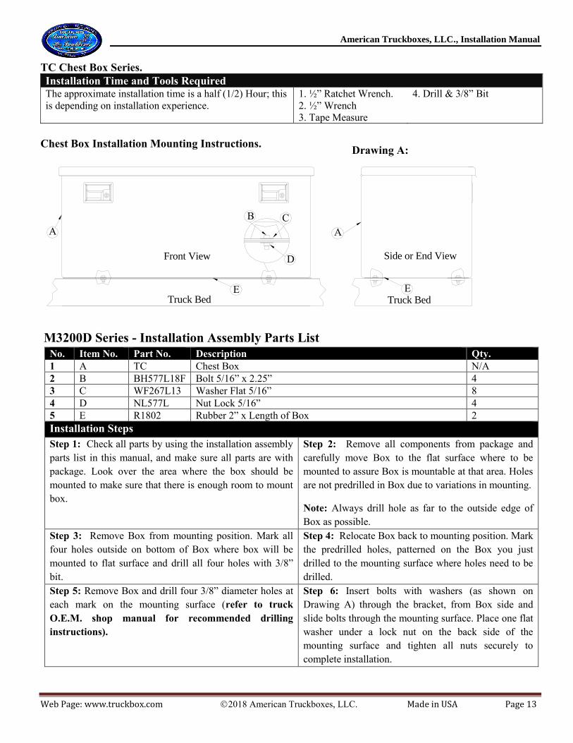
Chest Box Installation Mounting Instructions.
Front View Side or End View
Truck Bed Truck BedE
AA
E
CB
D
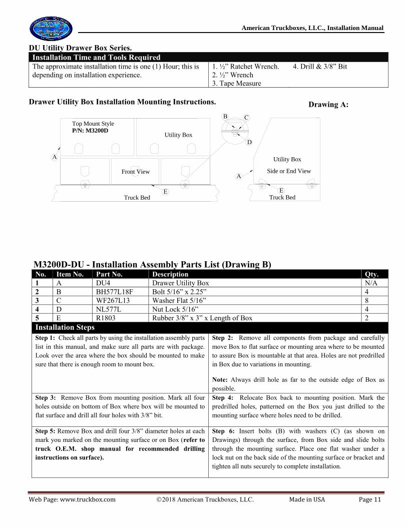
M3200D Series - Installation Assembly Parts List
No. Item No. Part No. Description Qty.
1 A TC Chest Box N/A
2 B BH577L18F Bolt 5/16” x 2.25” 4
3 C WF267L13 Washer Flat 5/16” 8
4 D NL577L Nut Lock 5/16” 4
5 E R1802 Rubber 2” x Length of Box 2
Installation Steps
Step 1: Check all parts by using the installation assembly
parts list in this manual, and make sure all parts are with
package. Look over the area where the box should be
mounted to make sure that there is enough room to mount
box.
Step 2: Remove all components from package and
carefully move Box to the flat surface where to be
mounted to assure Box is mountable at that area. Holes
are not predrilled in Box due to variations in mounting.
Note: Always drill hole as far to the outside edge of
Box as possible.
Step 3: Remove Box from mounting position. Mark all
four holes outside on bottom of Box where box will be
mounted to flat surface and drill all four holes with 3/8”
bit.
Step 4: Relocate Box back to mounting position. Mark
the predrilled holes, patterned on the Box you just
drilled to the mounting surface where holes need to be
drilled.
Step 5: Remove Box and drill four 3/8” diameter holes at
each mark on the mounting surface (refer to truck
O.E.M. shop manual for recommended drilling
instructions).
Step 6: Insert bolts with washers (as shown on
Drawing A) through the bracket, from Box side and
slide bolts through the mounting surface. Place one flat
washer under a lock nut on the back side of the
mounting surface and tighten all nuts securely to
complete installation.
Drawing A:
American Truckboxes, LLC., Installation Manual
Web Page: www.truckbox.com 2018 American Truckboxes, LLC. Made in USA Page 14
AFT A-Frame Box Series.
Installation Time and Tools Required The approximate installation time is a half (1/2) Hour; this
is depending on installation experience.
1. 5/16” Nut Setter Tip.
2. Tape Measure
3. Drill & ¼” Bit
A-Frame Box Installation Mounting Instructions.
Front View
Side or End View
A-Frame A-FrameD
AA
D
CB
M3300F Installation Assembly Parts List No. Item No. Part No. Description Qty.
1 A AFT A-Frame Box N/A
2 B SH577K15 Screw Self Drilling #14 x 1.5” 4
3 C WF267J13 Washer Flat 1/4” 4
4 D R1803 Rubber 3” x Length of Box 2
Installation Steps
Step 1: Check all parts by using the installation assembly parts
list in this manual, and make sure all parts are with package.
Look over the area where the box should be mounted to make
sure that there is enough room to mount box.
Step 2: Remove all components from package and carefully
move Box to the A-Frame surface where to be mounted to
assure Box is mountable at that area. Holes are not predrilled
in Box due to variations in mounting.
Note: Always drill hole as far to the outside edge of Box as
possible.
Step 3: Mark Box on bottom, by outlining both frames where
box will be mounted. Remove Box from mounting position and
flip box upside down on a pad. Make a center line between each
set of outlining lines that outline the frame where box was
resting on. Mark three holes per side, one in the center of center
line, two far to the outside edge of box as possible. Drill all six
holes with ¼” bit as marked.
Step 4: Apply one 3” rubber on each side to bottom of Box,
centered on center line the full length of Box. Relocate Box
back to mounting position. Screw all six self drilling screws
with washer in with drill and nut setter and tighten screws to
finish installation. (refer to trailer O.E.M. shop manual for
recommended drilling instructions).
Drawing A:
American Truckboxes, LLC., Installation Manual
Web Page: www.truckbox.com 2018 American Truckboxes, LLC. Made in USA Page 15
TS, TL & TT Series Auxiliary Fuel Tank
Installation Time and Tools Required The approximate installation time is two (1) Hours; this
is depending on installation experience.
1. Ratchet Wrench.
2. Wrench
3. Drill & Bit
4. Tape Measure
Auxiliary Tank Installation Instructions.
M3712-TMK Kit M3715-TMK Kit
No. Item Part No. Description Qty. Part No. Description Qty.
1 A Tank Fuel Tank/Box N/A Tank Fuel Tank/Box N/A
2 B BH858N22 3/8” x 3-1/4” Bolt 4 BH858N24 1/2” x 3-3/4” Bolt 4
Installation Steps Step 1: Check all parts by using the installation assembly parts
listed and make sure all parts are with package.
Step 2: Look over the area where the Tank should be mounted to
make sure that there is enough room to mount Tank and how to
best install the Tank
Step 3: Remove all components from package and locate Tank
where it is to be mounted to assure Tank is mountable at that
area. If Tank has a tool box make sure lid can open.
Step 4: Square Tank and mark the four holes on truck bed where
the Tank is to be mounted. Check truck wiring and hoses under
bed if none are path of your marked holes.
Step 5: Relocate the Tank to the side and drill all four holes in
truck bed. The holes size will depend on the mounting kit (see
chart above).
Step 6: After drilling the holes, clean the box from drilling debris
or dirt. Cut the 2” neoprene to the same length as tank depth and
apply to the truck box ridges on top part at four different locations.
Note: For installing Fuel Tank Kit, see Tank Kit Installation Sheet.
Step 7: Relocate tank back to mounting position and install the
bolts, washers, bushings, springs, and nuts as shown on drawing
Option 1 or Drawing B.
Step 8: Tighten all the nuts firmly. This should allow the tank to
anchored to the floor and still be able to shift if the truck box
twists
Notes. Use touch-up paint on any drilled holes to prevent oxidation or rust Caution: 1. Use an aluminum or light weight pump on aluminum Tanks, using a heavy pump can damage tank! 2. Never mount fuel
Tank directly to truck frame, or without the spring-loaded kit, for this can case tank failure and will void Tank warranty.
Drawing A:
Drawing B:
American Truckboxes, LLC., Installation Manual
Web Page: www.truckbox.com 2018 American Truckboxes, LLC. Made in USA Page 16
Fuel Connection Kits - Installation Sheet for TS, TL & TT Series
Installation Time and Tools Required The approximate installation time is two (2) Hours; this
is depending on installation experience.
1. Hose cutter.
2. Adj. wrench
3. Nut driver
4. ¾” bit & drill
Auxiliary Tank Installation Instructions.
“Professional installation by a certified technician is strongly recommended” Not responsible for altered products. No claims are made regarding any lifting devices. Any and all claims implied in this document excluded.
FTIK-10, FTIK-20 & FTIK-30 Kits No. Part No. Description Fill Line Size
Installation Assembly & Service Parts List. No. Item
No.
Part No. Description Qty.
1 A M2236/48/60 Mount Bracket Heavy Duty Top Mount (3 Piece) 2
2 B BR577L13 Bolt 5/16” x 1” Serrated 32
3 C WF267L13 Washer Flat 5/16” 32
4 D NL858L Nut Lock 5/16” 32
5 E Box Box N/A
Installation Steps
Step 1: Check all parts by using the parts list in Drawing A, to make sure all
parts are with mounting kit. Look over the area where the bracket or box
should be mounted to make sure that there is enough room to mount brackets
or box.
Step 2: Remove mounting brackets from the package. Assemble both
mounting brackets (A) together with the end pieces (1) like shown on Drawing
A, by using bolts (G), Washers (C) and locknuts (D). Adjust mount ends to
correct box width to correct adjustment for bracket to be mounted to deck and
tighten bolts. Carefully move brackets to deck where to be mounted. Secure
brackets to deck with two clamps to hold brackets in place.
Step 3: Mark the predrilled holes, patterned on the brackets to the deck
channel supports where holes need to be drilled. Mark holes as far too both
ends of brackets as possible, for best mounting result (this will be regulated by
the deck support channels). Relocate mount brackets and drill four 3/8” holes
in deck support channels per bracket (refer to truck O.E.M. manual for
recommended frame drilling instructions).
Step 4: Relocate mounting brackets back to the mounting area. Insert bolts
with washers (as shown on Drawing A (1)) through the bracket, from bracket
side and slide bolts through the deck supports. Place one flat washer under a
lock nut on the back side of the deck support and tighten all nuts securely to
complete installation of mounting bracket.
Step 5: Move Box to mounting brackets and center box under mounting
brackets. Use blocks or a lift device to hold box in place at mounting brackets.
Mark all eight holes using mounting brackets predrilled holes. Allow box to
drop down so holes can be drilled.
Step 6: Drill all eight holes with 3/8” bit on Box and relocate Box back to
Mounting position. Insert bolts with washers (as shown on Drawing A (2))
through the bracket, from bracket side and slide bolts through the Box. Place
one flat washer under a lock nut on the inside of Box and tighten all nuts
securely to complete installation of Box.
Drawing A:
Additional Warnings and
Precautions!
1. Never Drill Top or Bottom
Flange of Truck Frame or Trailer
Frame.
2. Never Weld Mounting
Brackets to Truck Frame or
Trailer Frame.
3. Never Mount Through the Top
or Back of Toolboxes.
American Truckboxes, LLC., Installation Manual
Web Page: www.truckbox.com 2018 American Truckboxes, LLC. Made in USA Page 28
Bumper BLB Series - Installation Mounting Instructions.
Diagram A:
SSBLB4L Installation Assembly Parts List No. Item
No.
Part No. Description Qty.
1 A SBLB Bumper N/A
2 B BH858R17 ½” x 2” Hex Bolt (Grade 8) 4
3 C WF858R ½” Lock Washer (Grade 8) 4
4 D NL858R ½” Nylon Lock Nut (Grade 8) 8
5 E SSLB-AS-14 ¼” Aluminum Spacers 4
Reflector or Reflection decals and License Plate Holder are optional.
Installation Steps Step 1: Check all parts by using the installation assembly parts list in
this manual, and make sure all parts are with package. Look over the
area where the Bumper should be mounted to make sure that there is
enough room to mount box.
Step 2: Remove all components from package and carefully move
Bumper to the frame where to be mounted, to assure Bumper is
mountable at that area. Holes are predrilled on Bumper for easy
mounting, but hole pattern may vary on truck.
Step 3: If hole pattern does not match, mark the predrilled holes
patterned, on the Truck Frame where holes need to be drilled. Remove
Bumper and drill four 1/2” diameter holes at each mark on the frame
(refer to truck O.E.M. shop manual for recommended frame
drilling instructions).
Step 6: Relocate Bumper to the frame. Insert Bolts with washers,
through the holes (as shown on Drawing A). Add spacers and place
one flat washer under a lock nut and tighten all nuts securely to
complete installation.
Note: Check and tighten bolts periodically. Note. If spacing is required due to truck frame design, place an aluminum spacer between bumper mount and truck frame as shown on diagram above.
Bumper Wiring Diagram Instructions.
Maintaining &
Caring for Your
Box.
Check and tighten
bolts periodically.
Additional Warnings and Precautions!
1. Never Drill Top or Bottom Flange of
Truck Frame or Trailer Frame.
2. Never Weld Mounting Brackets to
Truck Frame or Trailer Frame.
3. Never Mount Through the Top or Back
of Toolboxes.
American Truckboxes, LLC., Installation Manual
Web Page: www.truckbox.com 2018 American Truckboxes, LLC. Made in USA Page 29
Special Notice
This manual contains drawings and written material, which are for the sole purpose of mounting and providing guidelines for
installing our boxes and/or equipment in various configurations. Keep in mind that these are only intended as guidelines and not to
be construed as construction drawings or specifications.
America Truckboxes, LLC shall not be responsible in any way for anything other than the providing of equipment and materials
ordered. Guidelines shown in this manual may not meet or be in accordance with local, state, or federal regulations in effect at time
of installation.
American Truckboxes, LLC has the right to make changes in design at any time without notice.
Office Hours
Monday through Friday - 8:00am to 11:45am and 1:00pm to 5:00pm
American Truckboxes, LLC. 15750 6th Street SE, Blanchard, ND 58009