WARNING RISK OF FIRE • To reduce the risk of severe injury or death, follow all installation instructions. • • Install the clothes dryer according to these instructions and in accordance with local codes. • This dryer must be exhausted to the outdoors. • Use only rigid metal 4” diameter ductwork inside the dryer cabinet and use only UL approved transition ducting between the dryer and the home duct. • and installed in accordance with the instructions found in “Connecting materials are known to collapse, be easily crushed, and trap lint. These • Do not install or store this appliance in any location where it could be exposed to water and or weather. • NOTE: Installation and service of this dryer requires basic mechanical and electrical skills. It is your responsibility to contact Installation Instructions Electric Dryer 02 Questions on Installation? Call: 800.GE.CARES (US) or visit our Web site at: www.GEAppliances.com (US) BEFORE YOU BEGIN Read these instructions completely and carefully. • IMPORTANT- Save these instructions for local inspector’s use. • IMPORTANT- Observe all governing codes and ordinances. • Note to Installer - instructions with the customer. • Note to Customer - Keep these instructions with your Owner’s Manual for future reference. • or discarded, remove the dryer door. • Service information and the wiring diagram are located in the control console. • Do not allow children on or in the appliance. Close supervision of children isnecessary when the appliance is used near children. • Install the dryer where the temperature is dryer control system. • Product failure due to improper installation is not covered under the Warranty. TOOLS YOU WILL NEED PHILLIPS SCREWDRIVER SLIP JOINT PLIERS LEVEL FLAT BLADE SCREWDRIVER MATERIALS YOU WILL NEED GLOVES SAFETY GLASSES DRYER POWER CORD KIT (NOT PROVIDED WITH DRYER) 4" DUCT CLAMPS (2) OR 4" SPRING CLAMPS (2) EXHAUST HOOD 3/4" STRAIN RELIEF UL RECOGNIZED 4" DIA. METAL ELBOW 4" DIA. FLEXIBLE METAL (SEMI-RIGID) UL LISTED TRANSITION DUCT (IF NEEDED) KIT WX08X10077 (INCLUDES 2 ELBOWS) 4" DIA. METAL DUCT (RECOMMENDED) 4" DIA. FLEXIBLE METAL (FOIL TYPE) UL LISTED TRANSITION DUCT (IF NEEDED.) DUCT TAPE UL RATED 120/240V,30A WITH 3 OR 4 PRONGS. IDENTIFY THE PLUG TYPE AS PER THE HOUSE RECEPTACLE BEFORE PURCHASING LINE CORD. 4” COVER PLATE (IF NEEDED (KIT WE1M454) Minimum Clearance Other Than Alcove or Closet Installation Consideration must be given to provide adequate clearance for installation and service. 234D2008P002 31-16726-1 03-14 GE Printed in Mexico
Transcript
WARNING RISK OF FIRE• To reduce the risk of severe injury or death, follow all installation
instructions.• • Install the clothes dryer according to these instructions and in accordance
with local codes.• This dryer must be exhausted to the outdoors.• Use only rigid metal 4” diameter ductwork inside the dryer cabinet and use
only UL approved transition ducting between the dryer and the home duct.•
and installed in accordance with the instructions found in “Connecting
materials are known to collapse, be easily crushed, and trap lint. These
• Do not install or store this appliance in any location where it could be exposed to water and or weather.
•
NOTE: Installation and service of this dryer requires basic mechanical and electrical skills. It is your responsibility to contact
InstallationInstructions
Electric Dryer02
Questions on Installation? Call: 800.GE.CARES (US)or visit our Web site at: www.GEAppliances.com (US)
BEFORE YOU BEGINRead these instructions completely and carefully.
• IMPORTANT- Save these instructions for local inspector’s use.
• IMPORTANT- Observe all governing codes and ordinances.
• Note to Installer -instructions with the customer.
• Note to Customer - Keep these instructions with your Owner’s Manual for future reference.
• or discarded, remove the dryer door.
• Service information and the wiring diagram are located in the control console.
• Do not allow children on or in the appliance. Close supervision of children isnecessary when the appliance is used near children.
• Install the dryer where the temperature is
dryer control system.• Product failure due to improper installation
is not covered under the Warranty.
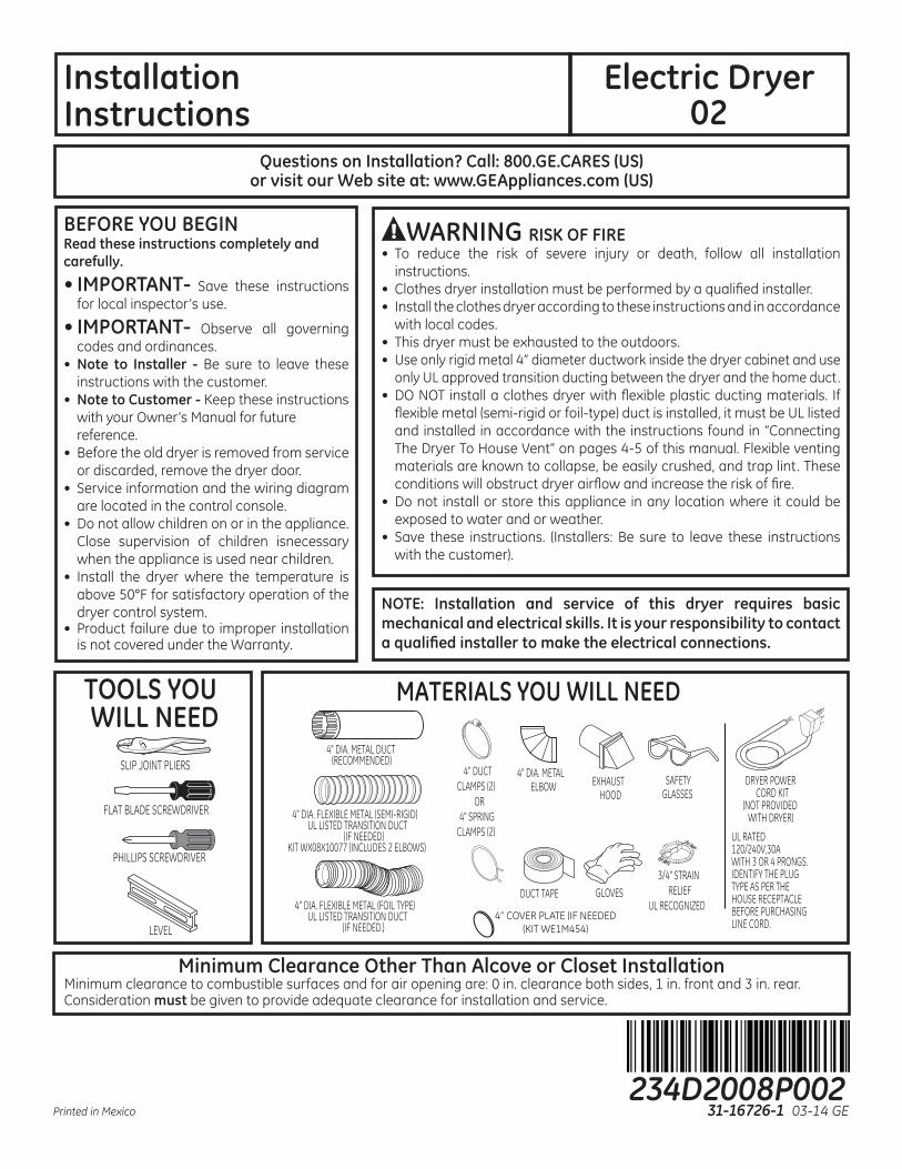
TOOLS YOUWILL NEED
PHILLIPS SCREWDRIVER
SLIP JOINT PLIERS
LEVEL
FLAT BLADE SCREWDRIVER
MATERIALS YOU WILL NEED
GLOVES
SAFETYGLASSES
DRYER POWERCORD KIT
(NOT PROVIDEDWITH DRYER)
4" DUCTCLAMPS (2)
OR4" SPRING
CLAMPS (2)
EXHAUSTHOOD
3/4" STRAINRELIEF
UL RECOGNIZED
4" DIA. METALELBOW
4" DIA. FLEXIBLE METAL (SEMI-RIGID)UL LISTED TRANSITION DUCT
(IF NEEDED) KIT WX08X10077 (INCLUDES 2 ELBOWS)
4" DIA. METAL DUCT(RECOMMENDED)
4" DIA. FLEXIBLE METAL (FOIL TYPE)UL LISTED TRANSITION DUCT
(IF NEEDED.)
DUCT TAPE
UL RATED 120/240V,30A WITH 3 OR 4 PRONGS. IDENTIFY THE PLUG TYPE AS PER THE HOUSE RECEPTACLE BEFORE PURCHASING LINE CORD.
4” COVER PLATE (IF NEEDED(KIT WE1M454)
Minimum Clearance Other Than Alcove or Closet Installation
Consideration must be given to provide adequate clearance for installation and service.
234D2008P00231-16726-1 03-14 GEPrinted in Mexico
Installation Instructions
2
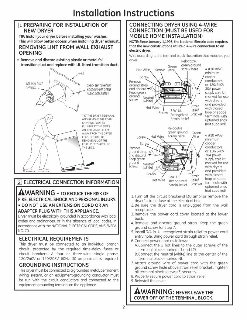
PREPARING FOR INSTALLATION OF NEW DRYER
TIP: Install your dryer before installing your washer.This will allow better access when installing dryer exhaust.
REMOVING LINT FROM WALL EXHAUST OPENING
• Remove and discard existing plastic or metal foil transition duct and replace with UL listed transition duct.
ELECTRICAL CONNECTION INFORMATION
WARNING - TO REDUCE THE RISK OF FIRE, ELECTRICAL SHOCK AND PERSONAL INJURY:• DO NOT USE AN EXTENSION CORD OR AN ADAPTER PLUG WITH THIS APPLIANCE.Dryer must be electrically grounded in accordance with local codes and ordinances, or in the absence of local codes, in
CONNECTING DRYER USING 4-WIRE CONNECTION (MUST BE USED FOR MOBILE HOME INSTALLATION)NOTE: Since January 1,1996, the National Electric code requires that the new constructions utilize a 4-wire connection to an electric dryer.Wire according to the terminal block illustration that matches your
dryer’s circuit fuse at the electrical box.
receptacle.
back.4. Remove and discard ground strap. Keep the green
ground screw for step 7.
A. Connect the 2 hot lines to the outer screws of the
7. Attach ground wire of power cord with the green
8. Properly secure power cord to strain relief.9. Reinstall the cover.
INTERNAL DUCTOPENING CHECK THAT EXHAUST
HOOD DAMPER OPENSAND CLOSES FREELY.
WALL
TILT THE DRYER SIDEWAYSAND REMOVE THE FOAMSHIPPING PADS BYPULLING AT THE SIDESAND BREAKING THEMAWAY FROM THE DRYERLEGS. BE SURE TOREMOVE ALL OF THEFOAM PIECES AROUNDTHE LEGS.
ELECTRICAL REQUIREMENTSThis dryer must be connected to an individual branch
GROUNDING INSTRUCTIONSThis dryer must be connected to a grounded metal, permanent
be run with the circuit conductors and connected to the equipment grounding terminal on the appliance.
WARNING: NEVER LEAVE THE COVER OFF OF THE TERMINAL BLOCK.
1
2
minimum copper conductors
power supply cord kit marked for use with dryers and provided with closed loop or spade terminals with upturned ends
Hot Wire
Hot Wire
Wire
Relocatre green ground screw here
Neutral
Strain Relief
Strain Relief
Screw
Screw
ScrewRemove ground strap and discard. Keep green ground screw.
Installation InstructionsCONNECTING DRYER USING 3-WIRE CONNECTION
3-wire ConnectionNot for use in Canada.DO NOT use for Mobile Home Installations.NOT for use on new construction.NOT for use on recreational vehicles.NOT for use in areas where local codes prohibit grounding through the neutral conduction.
dryer’s circuit fuse at the electrical box.
A. Connect the 2 hot lines to the outer screws of the
terminal of block and to green ground screw on cabinet
7. Properly secure power cord to strain relief.
8. Reinstall the cover.
WARNING: NEVER LEAVE THECOVER OFF OF THE TERMINAL BLOCK.
to grounded metal, cold water pipe, or other established ground determined by a qualified electrician.
Wire according to the terminal block illustration that matches
minimum copper conductors or
power supply cord kit marked for use with dryers and provided with closed loop or spade terminals with upturned
Hot Wire
Hot Wire
ground screwNeutral
Strain Relief
Strain Relief
Screw
Screw
Screw
Strap
minimum copper conductors or
power supply cord kit marked for use with dryers and provided with closed loop or spade terminals with upturned
Hot Wire
Hot Wire
ground screwNeutral
Strain Relief
Strain Relief
Screw
Screw
Screw
Strap
4
Installation Instructions3 EXHAUST INFORMATION
WARNING - IN CANADA AND IN THE UNITED STATES, THE REQUIRED EXHAUST DUCT DIAMETER IS 4 in (102mm). DO NOT USE DUCT LONGER THAN SPECIFIED IN THE EXHAUST LENGTH TABLE.
• Increase the drying times and the energy cost.• Reduce the dryer life.
The correct exhaust installation is YOUR RESPONSIBILITY. Problems due to incorrect installation are not covered by the warranty.Remove and discard existing plastic or metal foil transition duct and replace with UL listed transition duct.The MAXIMUM ALLOWABLE duct length and number of bends of the exhaust system depends upon the type of duct, number
noted below. The maximum duct length for rigid metal duct is shown in the table below.
• • • •
EXHAUST SYSTEM CHECK LISTHOOD OR WALL CAP• Terminate in a manner to prevent back drafts or entry of birds or other wildlife.
clogging.• Never install a screen in or over the exhaust duct. This could cause lint build up.•
4" DIA.
4"
4" DIA.
4" DIA.
2-1/2"
RECOMMENDED MAXIMUM LENGTHExhaust Hood Types
Recommended
No. of 90°Elbows
RigidMetal
RigidMetal
150 Feet135 Feet125 Feet115 Feet105 Feet
125 Feet115 Feet105 Feet
95 Feet85 Feet
01234
Use only for shortrun installations
5 95 Feet 75 Feet
EXHAUST LENGTHFOR LONG VENT MODELS
4" DIA.
4"
4" DIA.
4" DIA.
2-1/2"
RECOMMENDED MAXIMUM LENGTHExhaust Hood Types
Recommended
No. of 90°Elbows
RigidMetal
RigidMetal
90 Feet60 Feet45 Feet35 Feet25 Feet
60 Feet45 Feet35 Feet25 Feet15 Feet
01234
Use only for shortrun installations
EXHAUST LENGTHFOR NORMAL VENT MODELS
Installation Instructions
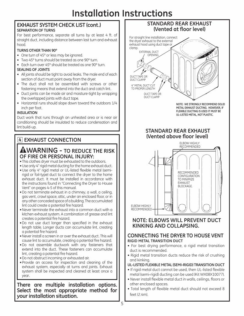
4 EXHAUST CONNECTION
There are multiple installation options. Select the most appropriate method for your installation situation.
WARNING - TO REDUCE THE RISK OF FIRE OR PERSONAL INJURY:• This clothes dryer must be exhausted to the outdoors.• Use only 4” rigid metal ducting for the home exhaust duct.
exhaust duct. It must be installed in accordance with the instructions found in “Connecting the Dryer to House
• Do not terminate exhaust in a chimney, a wall, a ceiling,
any other concealed space of a building. The accumulated
• Never terminate the exhaust into a common duct with a kitchen exhaust system. A combination of grease and lint
length table. Longer ducts can accumulate lint, creating
• Never install a screen in or over the exhaust duct. This will
• Do not assemble ductwork with any fasteners that extend into the duct. These fasteners can accumulate
• Do not obstruct incoming or exhausted air.• Provide an access for inspection and cleaning of the
exhaust system, especially at turns and joints. Exhaust system shall be inspected and cleaned at least once a year.
CONNECTING THE DRYER TO HOUSE VENTRIGID METAL TRANSITION DUCT
duct is recommended.• Rigid metal transition ducts reduce the risk of crushing
and kinking.UL-LISTED FLEXIBLE METAL (SEMI-RIGID) TRANSITION DUCT
other enclosed spaces.
DUCT TAPE ORDUCT CLAMP
DUCT TAPE ORDUCT CLAMP
4" METAL DUCT CUTTO PROPER LENGTH
EXTERNAL DUCTOPENING
For straight line installation, connect the dryer exhaust to the external exhaust hood using duct tape or clamp.
NOTE: WE STRONGLY RECOMMEND SOLID METAL EXHAUST DUCTING. HOWEVER, IF FLEXIBLE DUCTING IS USED IT MUST BE UL-LISTED METAL, NOT PLASTIC.
STANDARD REAR EXHAUST
STANDARD REAR EXHAUST
NOTE: ELBOWS WILL PREVENT DUCT KINKING AND COLLAPSING.
EXHAUST SYSTEM CHECK LIST (cont.)SEPARATION OF TURNS
straight duct, including distance between last turn and exhaust hood.TURNS OTHER THAN 90º
SEALING OF JOINTS• All joints should be tight to avoid leaks. The male end of each
section of duct must point away from the dryer.• The duct shall not be assembled with screws or other
fastening means that extend into the duct and catch lint.
the overlapped joints with duct tape.
inch per foot.INSULATIONDuct work that runs through an unheated area or is near air conditioning should be insulated to reduce condensation and
6
Installation Instructions
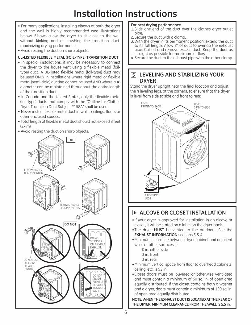
LEVELING AND STABILIZING YOUR DRYER
the 4 leveling legs, at the corners, to ensure that the dryer is level from side to side and front to rear.
6 ALCOVE OR CLOSET INSTALLATION• If your dryer is approved for installation in an alcove or
closet, it will be stated on a label on the dryer back.• The dryer MUST be vented to the outdoors. See the
EXHAUST INFORMATION• Minimum clearance between dryer cabinet and adjacent
• Closet doors must be louvered or otherwise ventilated
equally distributed. If the closet contains both a washer
of open area equally distributed.NOTE: WHEN THE EXHAUST DUCT IS LOCATED AT THE REAR OF THE DRYER, MINIMUM CLEARANCE FROM THE WALL IS 5.5 in.
5
LEVELSIDE-TO-SIDE
4 LEVELINGLEGS
LEVELFRONT-TO-BACK
without kinking and or crushing the transition duct,
• Avoid resting the duct on sharp objects.
UL-LISTED FLEXIBLE METAL (FOIL-TYPE) TRANSITION DUCT• In special installations, it may be necessary to connect
diameter can be maintained throughout the entire length of the transition duct.
other enclosed spaces.
• Avoid resting the duct on sharp objects.
For best drying performance
pipe.2. Secure the duct with a clamp.
to its full length. Allow 2” of duct to overlap the exhaust
4. Secure the duct to the exhaust pipe with the other clamp.
DRYER EXHAUST TO RIGHT, LEFT* OR BOTTOM CABINET
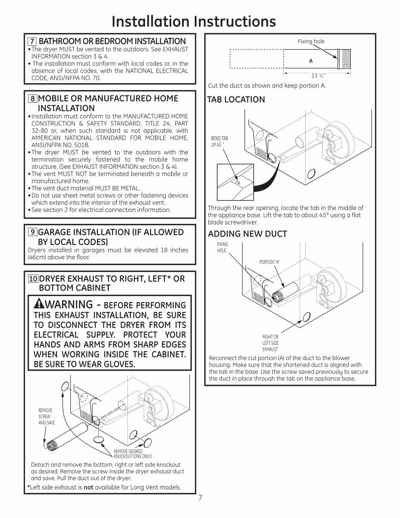
WARNING - BEFORE PERFORMING THIS EXHAUST INSTALLATION, BE SURE TO DISCONNECT THE DRYER FROM ITS ELECTRICAL SUPPLY. PROTECT YOUR HANDS AND ARMS FROM SHARP EDGES WHEN WORKING INSIDE THE CABINET. BE SURE TO WEAR GLOVES.
Installation Instructions
7
7 BATHROOM OR BEDROOM INSTALLATION
• The installation must conform with local codes or, in the absence of local codes, with the NATIONAL ELECTRICAL
MOBILE OR MANUFACTURED HOME INSTALLATION
• The dryer MUST be vented to the outdoors with the termination securely fastened to the mobile home
• The vent MUST NOT be terminated beneath a mobile or manufactured home.
• Do not use sheet metal screws or other fastening devices which extend into the interior of the exhaust vent.
• See section 2 for electrical connection information.
8 TAB LOCATION
ADDING NEW DUCTGARAGE INSTALLATION (IF ALLOWED BY LOCAL CODES)
9
Through the rear opening, locate the tab in the middle of the appliance base. Lift the tab to about 45º using a flat blade screwdriver.
BEND TABUP 45 o
Reconnect the cut portion (A) of the duct to the blower housing. Make sure that the shortened duct is aligned with the tab in the base. Use the screw saved previously to secure the duct in place through the tab on the appliance base.
RIGHT ORLEFT SIDEEXHAUST
PORTION "A"
FIXINGHOLE
Detach and remove the bottom, right or left side knockout as desired. Remove the screw inside the dryer exhaust duct and save. Pull the duct out of the dryer.
REMOVESCREWAND SAVE.
REMOVE DESIREDKNOCKOUT (ONE ONLY).
*Left side exhaust is not available for Long Vent models.
10
Cut the duct as shown and keep portion A.
A
2”
8
Installation InstructionsADDING ELBOW AND DUCT FOR EXHAUST TO LEFT OR RIGHT SIDE OF CABINET• Preassemble 4” elbow with 4” duct. Wrap duct tape
around joint.
opening and connect the elbow to the dryer internal duct.
CAUTION: Be sure not to pull or damage the electrical wires inside the dryer when inserting the duct.
• Apply duct tape as shown on the joint between the dryer internal duct and the elbow.
ADDING ELBOW FOR EXHAUST THROUGH BOTTOM OF CABINET• Insert the elbow through the rear opening and connect
it to the dryer internal duct.• Apply duct tape on the joint between the dryer internal
duct and elbow, as shown above.
EXHAUST CANBE ADDED TOLEFT OR RIGHT SIDE
DUCTTAPE
DUCTTAPE CAUTION:
Internal duct joints must be secured with tape, otherwise they may separate and cause a safety hazard.
ADDING COVER PLATE TO REAR OF CABINET (SIDES AND BOTTOM EXHAUST)
Connect standard metal elbows and ducts to complete
CAUTION:Internal duct joints must be secured with tape,otherwise they may separate and cause asafety hazard.
PL ATE(KIT WE1M454)
WARNING-NEVER LEAVE THE BACK OPENING WITHOUT THE PLATE
(Kit WE1M454).
Please go to www.GEAppliances.com or mail in
your product registration card.
ADVERTENCIA RIESGO DE INCENDIO• Para reducir el riesgo de una lesión grave o de muerte, cumpla con todas
las instrucciones de instalación.•
Instale la secadora de ropa de acuerdo con estas instrucciones y en cumplimiento de los códigos locales.
• Esta secadora debe tener una salida al exterior. • Utilice sólo un conducto rígido de metal de un diámetro de 4” dentro del
gabinete de la secadora y use sólo un conducto de transición aprobado por UL entre la secadora y el conducto doméstico.
•
aluminio), debe estar aprobado por UL e instalarse de acuerdo con las instrucciones de “Cómo conectar la secadora a la ventilación doméstica” de las páginas 4-5 de este manual. Los materiales de ventilación
condiciones obstruyen la corriente de aire de la secadora e incrementan el riesgo de incendio.
• No instale o almacene este aparato en un lugar donde se vea expuesto al agua y/o a las inclemencias del tiempo.
• instrucciones al consumidor).
NOTA: La instalación y reparación de esta secadora requieren capacidades mecánicas y eléctricas básicas. Es su responsabilidad
eléctricas.
Instrucciones de instalación
Secadora Eléctrica 02
¿Preguntas sobre la instalación? Llame al: 1-800-GECARES (EE.UU.) o visite nuestro sitio Web en: www.GEAppliances.com (EE.UU.)
ANTES DE COMENZARLea estas instrucciones por completo y con detenimiento.
• IMPORTANTE - Guarde estas instrucciones para el uso de inspectores locales.
• IMPORTANTE - códigos y ordenanzas vigentes.
• Nota al instalador -instrucciones con el consumidor.
• Nota al consumidor - Mantenga estas instrucciones con el Manual del Propietario para referencia futura.
•
• La información sobre reparaciones y el diagrama del cableado se encuentran en la consola de control.
estricta cuando el aparato es utilizado cerca de
• Instale la secadora en lugares donde la temperatura sea mayor a 50°F para un funcionamiento satisfactorio del sistema de control de la secadora.
• La garantía no cubre las fallas del producto debido a una instalación incorrecta.
HERRAMIENTASNECESARIAS
DESTORNILLADOR DE ESTRELLA
ALICATES DE JUNTA DESLIZANTE
NIVEL
DESTORNILLADOR PLANO
MATERIALES NECESARIOS
GUANTES
GAFAS DE SEGURIDAD
ABRAZADERAS DE CONDUCTO DE 4" (2)
OABRAZADERAS
DE RESORTE DE 4" (2)
CAMPANA DE SALIDA
ALIVIO DE TENSIÓN DE ¾” RECONOCIDO
POR UL
CODO DE METAL DE 4” DE DIÁ.
CONDUCTO DE TRANSICIÓN DE METAL FLEXIBLE (SEMI RÍGIDO) DE 4” DE DIÁ.
APROBADO POR UL (SI FUERA NECESARIO) KIT WX08X10077 (INCLUYE 2 CODOS)
CONDUCTO DE METAL DE 4” DE DIÁ(RECOMENDADO)
CONDUCTO DE TRANSICIÓN DE METAL FLEXIBLE (TIPO PAPEL DE ALUMINIO) DE 4” DE DIÁ.
APROBADO POR UL (SI FUERA NECESARIO)
CINTA ADHESIVA
KIT DE CABLE DE ENERGÍA DE LA SECADORA (NO PROVISTA CON LA SECADORA)CAPACIDAD UL DE220/240V,30ACON 3 O 4 PUNTAS.ANTES DE COMPRAR ELCORDÓN IDENTIFIQUEEL TIPO DE ENCHUFE DEACUERDO CON EL RECEPTÁCULODE LA CASA.
4 "PLACA DE CUBIERTA (SI ES NECESARIO
Espacio mínimo diferente a instalación en nichos o closets
frente y 3 pulg. en la parte trasera. Debe tenerse en cuenta un espacio libre adecuado para un funcionamiento y reparación correctos.
234D2008P00231-16726-1 03-14 GEImpreso en Mexico
Instrucciones de instalación
2
PREPARACIÓN PARA LA INSTALACIÓN DE UNA SECADORA NUEVA
CONSEJO: Instale su secadora antes de instalar la lavadora. Esto permitirá un mejor acceso cuando instale la salida de la secadora.
CÓMO QUITAR PELUSA DE LA ABERTURA DE LA SALIDA DE LA PARED
• plástico o de papel de aluminio y coloque un conducto de transición aprobado por UL.
INFORMACIÓN SOBRE CONEXIONES ELÉCTRICAS
ADVERTENCIA - PARA REDUCIR EL RIESGO DE INCENDIO, DESCARGA ELÉCTRICA Y LESIONES PERSONALES: • NO UTILICE UN CABLE DE EXTENSIÓN O UN ENCHUFE ADAPTADOR CON ESTE APARATO.La secadora debe contar con una conexión eléctrica a tierra en cumplimiento con los códigos y ordenanzas locales, o si éstos no existieran, de acuerdo con el CÓDIGO
CÓMO CONECTAR LA SECADORA USANDO UNA CONEXIÓN DE 4 CABLES (DEBE UTILIZARSE EN INSTALACIONES DE CASAS MÓVILES)NOTA: Desde el 1 de enero de 1996, el Código Eléctrico Nacional
cables a una secadora eléctrica.
del tomacorriente.3. Quite la tapa del cable de energía ubicada en la parte
trasera inferior. 4. Quite y descarte la cinta de conexión a tierra. Conserve
5. Instale un alivio de tensión de ¾ pulgadas reconocido
Pase el cable de energía a través del alivio de tensión.
9. Vuelva a instalar la tapa.
ABERTURA DE CONDUCTO INTERNA
PARED
VERIFIQUE QUE EL REGULADOR DE TIRO DE LA CAMPANA DE SALIDA SE ABRA Y CIERRE LIBREMENTE
INCLINE LA SECADORA DE COSTADO Y QUITE LAS ALMOHADILLAS DE ESPUMA PARA ENVÍO TOMÁNDOLAS DE LOS COSTADOS Y ARRANCÁNDOLAS DE LAS PATAS DE LA SECADORA. ASEGÚRESE DE QUITAR TODAS LAS PIEZAS DE ESPUMA UBICADAS ALREDEDOR DE LAS PATAS.
REQUISITOS ELÉCTRICOSEsta secadora debe conectarse a un circuito derivado individual, con la protección de los fusibles de tiempo
INSTRUCCIONES DE CONEXIÓN A TIERRAEsta secadora debe conectarse a un sistema de cableado permanente con conexión a tierra o debe utilizarse un
los conductores de circuito y conectarse a la terminal de conexión a tierra del aparato.
ADVERTENCIA: NUNCA OLVIDE DE VOLVER A COLOCAR LA TAPA DEL BLOQUE TERMINAL.
1
2
4 conductores
o kit de cable de suministro de energía de
marcado para su uso con secadoras y provisto con terminales de bucle cerrado
con extremos
Cable vivo
Cable vivo
Cable verde
Vuelva a colocar el tornillo verde de conexión
Neutral
tensión de 3/4” reconocido por UL
de alivio de tensión
Tornillo
Tornillo
Tornillo
Quite la cinta de conexión a tierra y descártela. Conserve el tornillo verde de conexión a tierra.
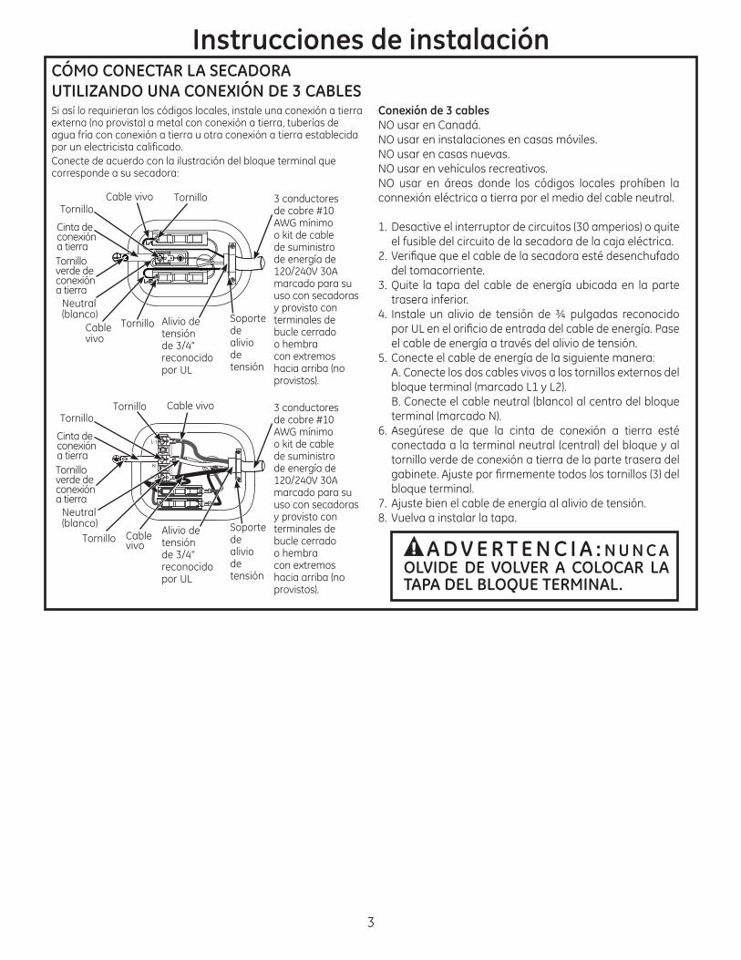
CÓMO CONECTAR LA SECADORA UTILIZANDO UNA CONEXIÓN DE 3 CABLES
agua fría con conexión a tierra u otra conexión a tierra establecida por un electricista calificado.
NO usar en Canadá.NO usar en instalaciones en casas móviles.NO usar en casas nuevas.
connexión eléctrica a tierra por el medio del cable neutral.
del tomacorriente.3. Quite la tapa del cable de energía ubicada en la parte
trasera inferior. 4. Instale un alivio de tensión de ¾ pulgadas reconocido
el cable de energía a través del alivio de tensión.
tornillo verde de conexión a tierra de la parte trasera del
8. Vuelva a instalar la tapa.
Instrucciones de instalación
3
A D V E R T E N C I A : N U N C A OLVIDE DE VOLVER A COLOCAR LA TAPA DEL BLOQUE TERMINAL.
3 conductores
o kit de cable de suministro de energía de
marcado para su uso con secadoras y provisto con terminales de bucle cerrado
con extremos
provistos).
Cable vivo
Cable vivo
Tornillo verde de conexión a tierra
Neutral
tensión de 3/4” reconocido por UL
de alivio de tensión
Tornillo
Tornillo
Tornillo
Cinta de conexión a tierra
Instrucciones de instalación
4
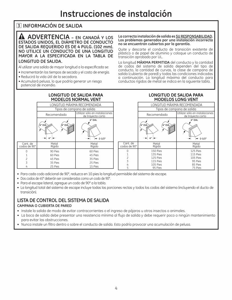
3 INFORMACIÓN DE SALIDA
ADVERTENCIA – EN CANADÁ Y LOS ESTADOS UNIDOS, EL DIÁMETRO DE CONDUCTO DE SALIDA REQUERIDO ES DE 4 PULG. (102 mm). NO UTILICE UN CONDUCTO DE UNA LONGITUD MAYOR A LA ESPECIFICADA EN LA TABLA DE LONGITUD DE SALIDA.
• Incrementarán los tiempos de secado y el costo de energía. • •
potencial de incendio.
La correcta instalación de salida es SU RESPONSABILIDAD. Los problemas generados por una instalación incorrecta no se encuentran cubiertos por la garantía.Quite y descarte el conducto de transición existente de
transición aprobado por UL.La longitud MÁXIMA PERMITIDA del conducto y la cantidad de codos del sistema de salida dependen del tipo de conducto, la cantidad de curvas, la clase de campana de
a continuación. La longitud máxima del conducto para conductos rígidos de metal se indica en la siguiente tabla.
• • Dos codos de 45° deberán ser considerados como un codo de 90°.• Para el escape lateral, agregue un codo de 90° a la tabla.•
transición).
4" DIA.
4"
4" DIA.
4" DIA.
2-1/2"
LONGITUD MÁXIMA RECOMENDADATipos de campana de salida
Recomendado
90 Pies60 Pies45 Pies35 Pies
60 Pies45 Pies35 Pies25 Pies
0123
25 Pies 15 Pies4
Utilizar sólo en instalacionesde trayecto corto
Cant. decodos de 90°
Metal Rígido
Metal Rígido
MODELOS NORMAL VENTLONGITUD DE SALIDA PARA
4" DIA.
4"
4" DIA.
4" DIA.
2-1/2"
150 Pies135 Pies125 Pies115 Pies105 Pies
125 Pies115 Pies105 Pies
95 Pies85 Pies
012345 95 Pies 75 Pies
MODELOS LONG VENTLONGITUD DE SALIDA PARA
LONGITUD MÁXIMA RECOMENDADATipos de campana de salida
Recomendado Utilizar sólo en instalacionesde trayecto corto
Cant. decodos de 90°
Metal Rígido
Metal Rígido
LISTA DE CONTROL DEL SISTEMA DE SALIDACAMPANA O CUBIERTA DE PARED
para evitar las obstrucciones. •
5
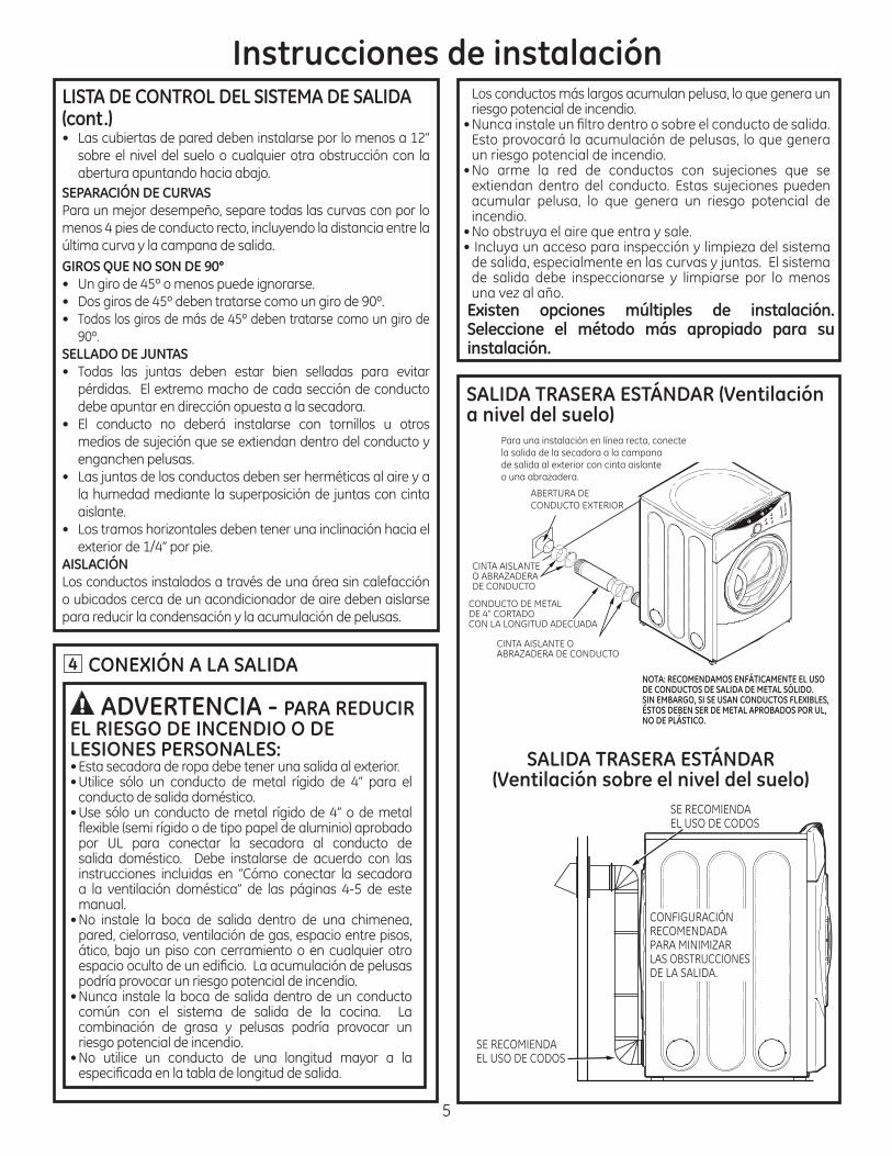
4 CONEXIÓN A LA SALIDA
ADVERTENCIA - PARA REDUCIR EL RIESGO DE INCENDIO O DE LESIONES PERSONALES:• Esta secadora de ropa debe tener una salida al exterior. • Utilice sólo un conducto de metal rígido de 4” para el
conducto de salida doméstico. • Use sólo un conducto de metal rígido de 4” o de metal
por UL para conectar la secadora al conducto de salida doméstico. Debe instalarse de acuerdo con las instrucciones incluidas en “Cómo conectar la secadora a la ventilación doméstica” de las páginas 4-5 de este manual.
pared, cielorraso, ventilación de gas, espacio entre pisos,
podría provocar un riesgo potencial de incendio. • Nunca instale la boca de salida dentro de un conducto
combinación de grasa y pelusas podría provocar un riesgo potencial de incendio.
• No utilice un conducto de una longitud mayor a la
NOTA: RECOMENDAMOS ENFÁTICAMENTE EL USO DE CONDUCTOS DE SALIDA DE METAL SÓLIDO. SIN EMBARGO, SI SE USAN CONDUCTOS FLEXIBLES, ÉSTOS DEBEN SER DE METAL APROBADOS POR UL, NO DE PLÁSTICO.
Para una instalación en línea recta, conecte la salida de la secadora a la campana de salida al exterior con cinta aislante o una abrazadera.
ABERTURA DE CONDUCTO EXTERIOR
CINTA AISLANTE O ABRAZADERA DE CONDUCTO
CONDUCTO DE METAL DE 4” CORTADO CON LA LONGITUD ADECUADA
CINTA AISLANTE O ABRAZADERA DE CONDUCTO
SALIDA TRASERA ESTÁNDAR (Ventilación a nivel del suelo)
SALIDA TRASERA ESTÁNDAR (Ventilación sobre el nivel del suelo)
SE RECOMIENDA EL USO DE CODOS
SE RECOMIENDA EL USO DE CODOS
CONFIGURACIÓN RECOMENDADA PARA MINIMIZAR LAS OBSTRUCCIONES DE LA SALIDA.
Seleccione el método más apropiado para su instalación.
riesgo potencial de incendio.
un riesgo potencial de incendio.
incendio.
• Incluya un acceso para inspección y limpieza del sistema
de salida debe inspeccionarse y limpiarse por lo menos
Instrucciones de instalaciónLISTA DE CONTROL DEL SISTEMA DE SALIDA (cont.)
SEPARACIÓN DE CURVAS
menos 4 pies de conducto recto, incluyendo la distancia entre la
GIROS QUE NO SON DE 90°
•
SELLADO DE JUNTAS
debe apuntar en dirección opuesta a la secadora. • El conducto no deberá instalarse con tornillos u otros
aislante.
AISLACIÓNLos conductos instalados a través de una área sin calefacción o ubicados cerca de un acondicionador de aire deben aislarse para reducir la condensación y la acumulación de pelusas.
6
Instrucciones de instalación
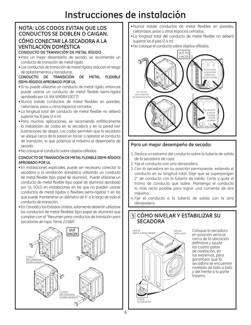
en posición vertical cerca de la ubicación
las cuatro patas de nivelación, en los extremos, para
secadora se encuentre nivelada de lado a lado y del frente a la parte trasera.
5
NOTA: LOS CODOS EVITAN QUE LOS CONDUCTOS SE DOBLEN O CAIGAN.
NIVELARLADO A LADO
4 PATAS DE NIVELACIÓN
NIVELARFRENTE A PARTE TRASERA
CODORECOMIENDA ENFÁTICAMENTE
CODOSRECOMIENDA ENFÁTICAMENTE
QUÉ HACER
CÓMO CONECTAR LA SECADORA A LA VENTILACIÓN DOMÉSTICACONDUCTO DE TRANSICIÓN DE METAL RÍGIDO
conducto de transición de metal rígido.• Los conductos de transición de metal rígidos reducen el riesgo
de aplastamientos y torceduras.CONDUCTO DE TRANSICIÓN DE METAL FLEXIBLE (SEMI-RÍGIDO) APROBADO POR UL
cielorrasos, pisos u otros espacios cerrados.
secado.
CONDUCTO DE TRANSICIÓN DE METAL FLEXIBLE (SEMI-RÍGIDO) APROBADO POR UL • En instalaciones especiales, puede ser necesario conectar la
secadora a la ventilación doméstica utilizando un conducto
conducto de transición. • En Canadá y los Estados Unidos, solamente deberán utilizarse
cumplan con el “Resumen para conductos de transición para
Para un mejor desempeño de secado:
Deslice un extremo del conducto sobre la tubería de salida de la secadora de ropa.
2. 3. Con la secadora en su posición permanente, extienda el
lo más recto posible para lograr una corriente de aire máxima.
4. abrazadera.
cielorrasos, pisos u otros espacios cerrados.
NO UTILICE UNA LONGITUD
DE SALIDA EXCESIVA
QUÉ NO HACER
NO COLOQUE LA SECADORA
SOBRE UNA SALIDA FLEXIBLE
NO APLASTE LA SALIDA
FLEXIBLE CONTRA
LA PARED
CÓMO NIVELAR Y ESTABILIZAR SU SECADORA
10 SALIDA DE LA SECADORA HACIA LA DERECHA, IZQUIERDA* O PARTE INFERIOR DEL GABINETE
ADVERTENCIA - ANTES DE EFECTUAR ESTA INSTALACIÓN DE SALIDA, ASEGÚRESE DE DESCONECTAR LA SECADORA DEL SUMINISTRO ELÉCTRICO. PROTEJA SUS MANOS Y BRAZOS DE LOS LADOS AFILADOS CUANDO TRABAJE DENTRO DEL GABINETE. ASEGÚRESE DE USAR GUANTES.
Instrucciones de instalación
Despegue y quite el recorte inferior, derecho o izquierdo, según corresponda. Quite el tornillo ubicado dentro
QUITE EL TORNILLO Y CONSÉRVELO
QUITE EL RECORTE DESEADO (SÓLO UNO)
7 INSTALACIÓN EN BAÑOS O DORMITORIOS• Esta secadora DEBE tener una ventilación al exterior. Ver
• La instalación debe cumplir con códigos locales o, si no
INSTALACIÓN EN CASAS MÓVILES O PREFABRICADAS
• La secadora DEBE tener ventilación al exterior con la
móvil o prefabricada. • • No utilice tornillos para placas de metal u otros dispositivos
de salida. • Ver la sección 2 sobre información sobre conexiones eléctricas.
8
INSTALACIÓN EN GARAJE (SI PERMITIDO POR LOS CODIGOS LOCALES)
9A través de la abertura trasera, ubique la lengüeta en el medio de la base del aparato. Levante la lengüeta hasta alrededor de 45°, utilizando un destornillador de lados planos.
GIRE LA LENGÜETA HASTA 45°
UBICACIÓN DE LA LENGÜETA
6 INSTALACIÓN EN NICHO O EN CLOSET
aparato. • Esta secadora DEBE tener una ventilación al exterior.
Ver la INFORMACIÓN SOBRE SALIDA secciones 3 y 4.
• El espacio libre mínimo entre el gabinete de la secadora
0 pulg. sobre ambos lados 3 pulg. en el frente 3 pulg. en la parte trasera• El espacio vertical mínimo desde el piso a los gabinetes
superiores, cielorraso, etc., es de 52 pulg.
tipo de ventilación y deben tener por lo menos 60 pulg.
el closet incluye una lavadora y una secadora, las puertas
espacio abierto distribuido uniformemente. NOTA: CUANDO EL CONDUCTO DE SALIDA ESTÁ UBICADO EN LA PARTE TRASERA DE LA SECADORA, EL ESPACIO LIBRE MÍNIMO DESDE LA PARED DEBE SER 5.5 PULGADAS.
* no aplica a los modelos Long Vent.
A
2
8
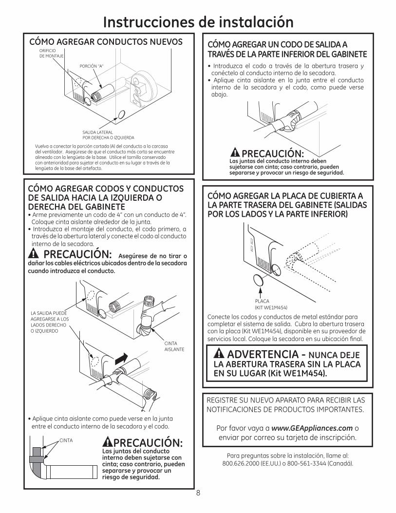
ADVERTENCIA - NUNCA DEJE LA ABERTURA TRASERA SIN LA PLACA EN SU LUGAR (Kit WE1M454).
Instrucciones de instalación
Vuelva a conectar la porción cortada (A) del conducto a la carcasa del ventilador. Asegúrese de que el conducto más corto se encuentre alineado con la lengüeta de la base. Utilice el tornillo conservado con anterioridad para sujetar el conducto en su lugar a través de la lengüeta de la base del artefacto.
SALIDA LATERAL POR DERECHA O IZQUIERDA
PORCIÓN “A”
ORIFICIO DE MONTAJE
LA SALIDA PUEDE AGREGARSE A LOS LADOS DERECHO O IZQUIERDO
CINTA AISLANTE
CÓMO AGREGAR CONDUCTOS NUEVOS
CINTA PRECAUCIÓN:Las juntas del conducto interno deben sujetarse con cinta; caso contrario, pueden separarse y provocar un riesgo de seguridad.
CÓMO AGREGAR LA PLACA DE CUBIERTA A LA PARTE TRASERA DEL GABINETE (SALIDAS POR LOS LADOS Y LA PARTE INFERIOR)
Conecte los codos y conductos de metal estándar para completar el sistema de salida. Cubra la abertura trasera
PRECAUCIÓN:Las juntas del conducto interno deben sujetarse con cinta; caso contrario, pueden separarse y provocar un riesgo de seguridad.
PLACA (KIT WE1M454)
Por favor vaya a www.GEAppliances.com o
CÓMO AGREGAR UN CODO DE SALIDA A TRAVÉS DE LA PARTE INFERIOR DEL GABINETE• Introduzca el codo a través de la abertura trasera y
conéctelo al conducto interno de la secadora.
interno de la secadora y el codo, como puede verse .
CÓMO AGREGAR CODOS Y CONDUCTOS DE SALIDA HACIA LA IZQUIERDA O DERECHA DEL GABINETE
través de la abertura lateral y conecte el codo al conducto interno de la secadora.
PRECAUCIÓN: dañar los cables eléctricos ubicados dentro de la secadora
entre el conducto interno de la secadora y el codo.