44
Signature Series Vehicles B8 A4/S4 Installation Guidelines STāSIS Engineering

Signature Series Vehicles B8 A4/S4 Installation Guidelines
STāSIS Engineering
Page 2 of 44
Table of Contents
Page Torque specs 3 Suspension
Front and Rear Suspension, Touring 4 Front and Rear Suspension, Challenge 12 Rear Anti-Roll Bar 25
Differential
Manual Transmission Center Differential
30
Exhaust 35
Exhaust Kit
Braking Monobloc Brake Kit 38 Bed-In Procedure 43
Post Installation Checklist 44

Page 3 of 44
B8 A4/S4 TORQUE VALUES Suspension and Wheels Front damper to upper mount 37 ft-lbs Front damper upper mount to body 56 ft-lbs Front damper fork pinch bolt 30 ft-lbs +
180º Front damper fork to lower link 66 ft-lbs Upper link pinch bolt 29 ft-lbs Rear damper to upper mount 26 ft-lbs Rear damper upper mount to body 37 ft-lbs Rear damper to upright 111 ft-lbs Rear sway bar link to lower control arm 30 ft-lbs Rear sway bar link to sway bar 30 ft-lbs Rear sway bar mounts 19 ft-lbs Wheel spacer bolts 90 ft-lbs Wheel lug bolts 90 ft-lbs Brakes Rotor set screw 48 in-lbs STaSIS Challenge bracket to upright 92 ft-lbs STaSIS Challenge caliper to bracket 70 ft-lbs Brake line to caliper 14 ft-lbs Exhaust Down pipe to mid pipe slip clamp 17 ft-lbs Hangers to body 17 ft-lbs Mufflers to mid pipe 17 ft-lbs Muffler adjustment bracket 17 ft-lbs Center Diff Torsen housing to transmission (short bolts) 7 ft-lbs +
90º Torsen housing to transmission (long bolts) 18 ft-lbs Tunnel crossmember to transmission mount 15 ft-lbs Tunnel crossmember to body 41 ft-lbs Driveshaft to output flange 30 ft-lbs Drive shaft heat shield 18 ft-lbs Tansmission drain plug 30 ft-lbs
Page 4 of 44
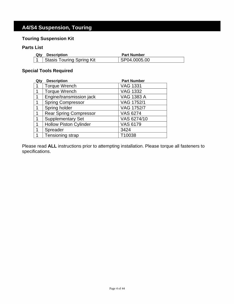
A4/S4 Suspension, Touring Touring Suspension Kit
Parts List Qty Description Part Number 1 Stasis Touring Spring Kit SP04.0005.00
Special Tools Required
Qty Description Part Number 1 Torque Wrench VAG 1331 1 Torque Wrench VAG 1332 1 Engine/transmission jack VAG 1383 A 1 Spring Compressor VAG 1752/1 1 Spring holder VAG 1752/7 1 Rear Spring Compressor VAS 6274 1 Supplementary Set VAS 6274/10 1 Hollow Piston Cylinder VAS 6179 1 Spreader 3424 1 Tensioning strap T10038
Please read ALL instructions prior to attempting installation. Please torque all fasteners to specifications.
Page 5 of 44
Front Removal and Install
1 Before removing any parts, park the car on a secure, stable, and level surface. Remove wheel trim; pull trim cap off light-alloy wheels (using puller in vehicle tool kit) and loosen (but do not remove) the wheel lug nuts. Jack the vehicle up, and place the car on four stable jack stands or use a professional vehicle lift. We recommend having two people available for certain steps of the installation.
2 Remove wheels
3 Before removing left suspension strut, remove headlight range control link from track control link. (2009 and older)
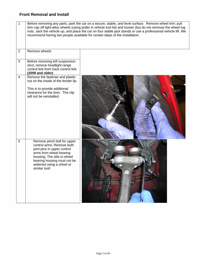
4 Remove the fastener and plastic nut on the inside of the fender lip. This is to provide additional clearance for the tires. The clip will not be reinstalled.
5 Remove pinch bolt for upper
control arms. Remove both joint pins in upper control arms from wheel bearing housing. The slits in wheel bearing housing must not be widened using a chisel or similar tool!
Page 6 of 44
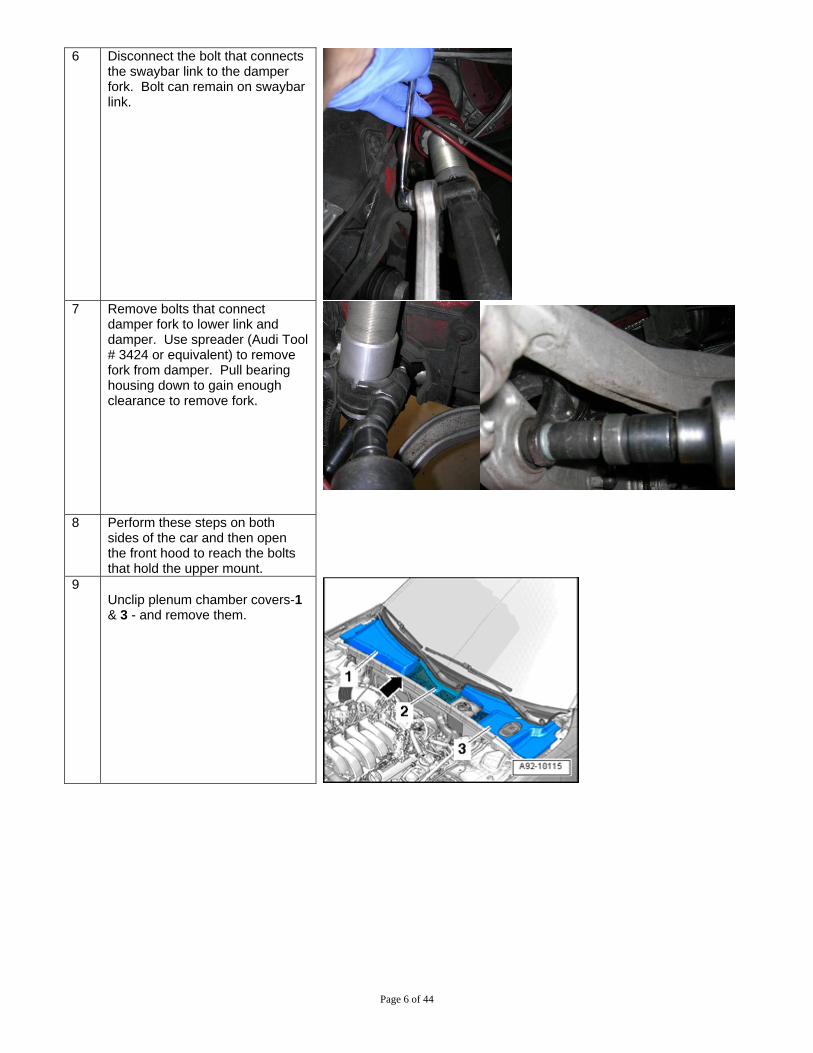
6 Disconnect the bolt that connects the swaybar link to the damper fork. Bolt can remain on swaybar link.
7 Remove bolts that connect
damper fork to lower link and damper. Use spreader (Audi Tool # 3424 or equivalent) to remove fork from damper. Pull bearing housing down to gain enough clearance to remove fork.
8 Perform these steps on both
sides of the car and then open the front hood to reach the bolts that hold the upper mount.
9 Unclip plenum chamber covers-1 & 3 - and remove them.

Page 7 of 44
10 Remove nut - 1 - . Remove filler neck - 3 - with filler tube from washer fluid reservoir and body opening - arrow B - .
11 Remove nuts - arrows - , move
coolant reservoir upward and lay it aside to access the mounting bolt.
Do not disconnect any coolant lines, reservoir does not have to be removed.
12 Remove bolts - arrows - and
remove suspension strut with the mounting bracket.
Remove similar bolts from passenger side and remove passenger side suspension strut with the mounting bracket.
13 Remove OEM damper and spring
from upper mount.
Page 8 of 44
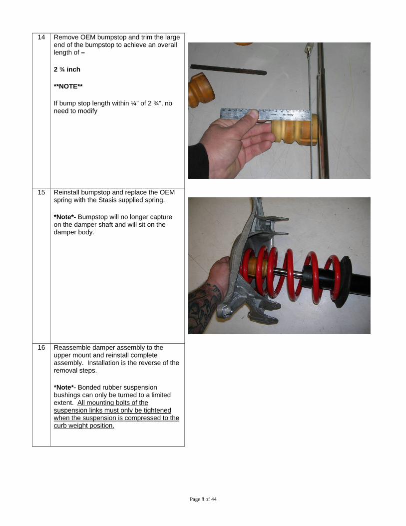
14 Remove OEM bumpstop and trim the large
end of the bumpstop to achieve an overall length of –
2 ¾ inch
**NOTE**
If bump stop length within ¼” of 2 ¾”, no need to modify
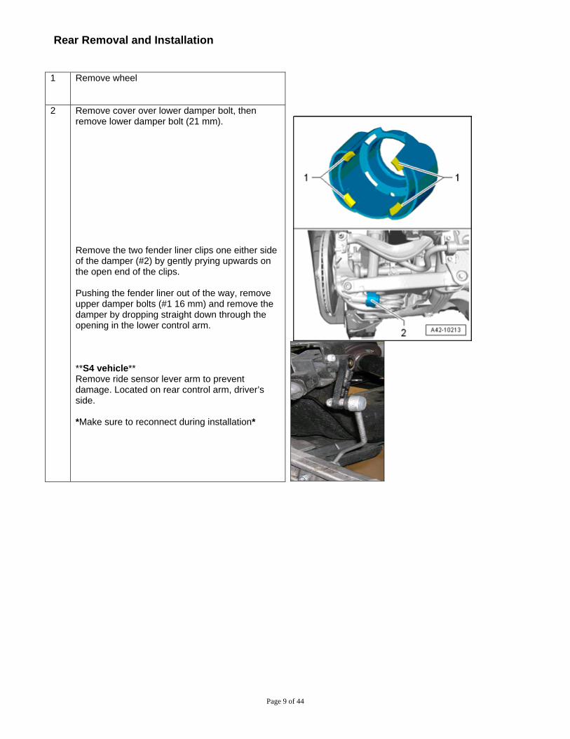
15 Reinstall bumpstop and replace the OEM
spring with the Stasis supplied spring.
*Note*- Bumpstop will no longer capture on the damper shaft and will sit on the damper body.
16 Reassemble damper assembly to the
upper mount and reinstall complete assembly. Installation is the reverse of the removal steps.
*Note*- Bonded rubber suspension bushings can only be turned to a limited extent. All mounting bolts of the suspension links must only be tightened when the suspension is compressed to the curb weight position.
Page 9 of 44
Rear Removal and Installation
1 Remove wheel
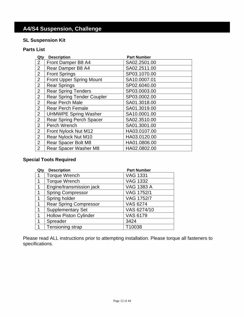
2 Remove cover over lower damper bolt, then remove lower damper bolt (21 mm). Remove the two fender liner clips one either side of the damper (#2) by gently prying upwards on the open end of the clips. Pushing the fender liner out of the way, remove upper damper bolts (#1 16 mm) and remove the damper by dropping straight down through the opening in the lower control arm. **S4 vehicle** Remove ride sensor lever arm to prevent damage. Located on rear control arm, driver’s side. *Make sure to reconnect during installation*

Page 10 of 44
3 Remove upper mount from damper and set aside.
4 Remove OEM bumpstop and trim the large end
of the bumpstop to achieve an overall length of –
4 3/8 inch **Note**
If bump stop length within ¼” of 2 ¾”, no need to modify
5 Remove rear coil springs with spring compressor tool VAS 6274 and VAS 6274/10.

Page 11 of 44
6 Install STaSIS rear spring with the spring compressor. Progressive coils towards the top.
7 Install damper assembly and torque to: Upper bolt: 37 ft-lbs Lower bolt: 111 ft-lb Note – Bonded rubber suspension bushings can only be turned to a limited extent. The mounting bolts of the suspension links must only be tightened when the suspension is compressed to the curb weight position.
8 Install wheels and tighten. Lower the car onto its wheels and torque all wheel lug bolts to the recommended torque. Note: Check wheel alignment after suspension installation
Page 12 of 44
A4/S4 Suspension, Challenge SL Suspension Kit
Parts List Qty Description Part Number 2 Front Damper B8 A4 SA02.2501.00 2 Rear Damper B8 A4 SA02.2511.00 2 Front Springs SP03.1070.00 2 Front Upper Spring Mount SA10.0007.01 2 Rear Springs SP02.6040.00 2 Rear Spring Tenders SP03.0003.00 2 Rear Spring Tender Coupler SP03.0002.00 2 Rear Perch Male SA01.3018.00 2 Rear Perch Female SA01.3019.00 2 UHMWPE Spring Washer SA10.0001.00 2 Rear Spring Perch Spacer SA02.3510.00 2 Perch Wrench SA01.3001.00 2 Front Nylock Nut M12 HA03.0107.00 2 Rear Nylock Nut M10 HA03.0120.00 2 Rear Spacer Bolt M8 HA01.0806.00 2 Rear Spacer Washer M8 HA02.0802.00
Special Tools Required
Qty Description Part Number 1 Torque Wrench VAG 1331 1 Torque Wrench VAG 1332 1 Engine/transmission jack VAG 1383 A 1 Spring Compressor VAG 1752/1 1 Spring holder VAG 1752/7 1 Rear Spring Compressor VAS 6274 1 Supplementary Set VAS 6274/10 1 Hollow Piston Cylinder VAS 6179 1 Spreader 3424 1 Tensioning strap T10038
Please read ALL instructions prior to attempting installation. Please torque all fasteners to specifications.
Page 13 of 44
Front Removal
1 Before removing any parts, park the car on a secure, stable, and level surface. Remove wheel trim; pull trim cap off light-alloy wheels (using puller in vehicle tool kit) and loosen (but do not remove) the wheel lug nuts. Jack the vehicle up, and place the car on four stable jack stands or use a professional vehicle lift. We recommend having two people available for certain steps of the installation.
2 Remove wheels
3 Before removing left suspension strut, remove headlight range control link from track control link.
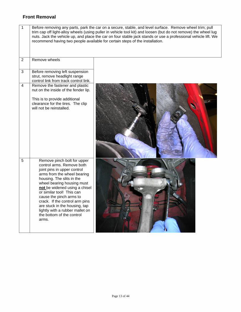
4 Remove the fastener and plastic nut on the inside of the fender lip. This is to provide additional clearance for the tires. The clip will not be reinstalled.
5 Remove pinch bolt for upper
control arms. Remove both joint pins in upper control arms from the wheel bearing housing. The slits in the wheel bearing housing must not be widened using a chisel or similar tool! This can cause the pinch arms to crack. If the control arm pins are stuck in the housing, tap lightly with a rubber mallet on the bottom of the control arms.
Page 14 of 44
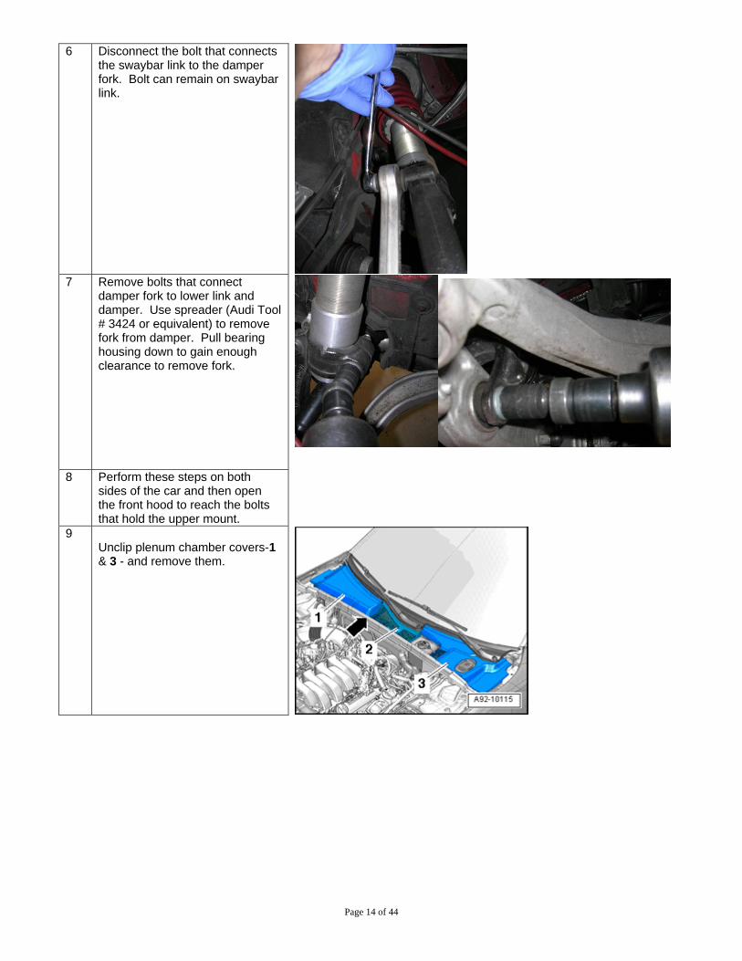
6 Disconnect the bolt that connects the swaybar link to the damper fork. Bolt can remain on swaybar link.
7 Remove bolts that connect
damper fork to lower link and damper. Use spreader (Audi Tool # 3424 or equivalent) to remove fork from damper. Pull bearing housing down to gain enough clearance to remove fork.
8 Perform these steps on both
sides of the car and then open the front hood to reach the bolts that hold the upper mount.
9 Unclip plenum chamber covers-1 & 3 - and remove them.
Page 15 of 44
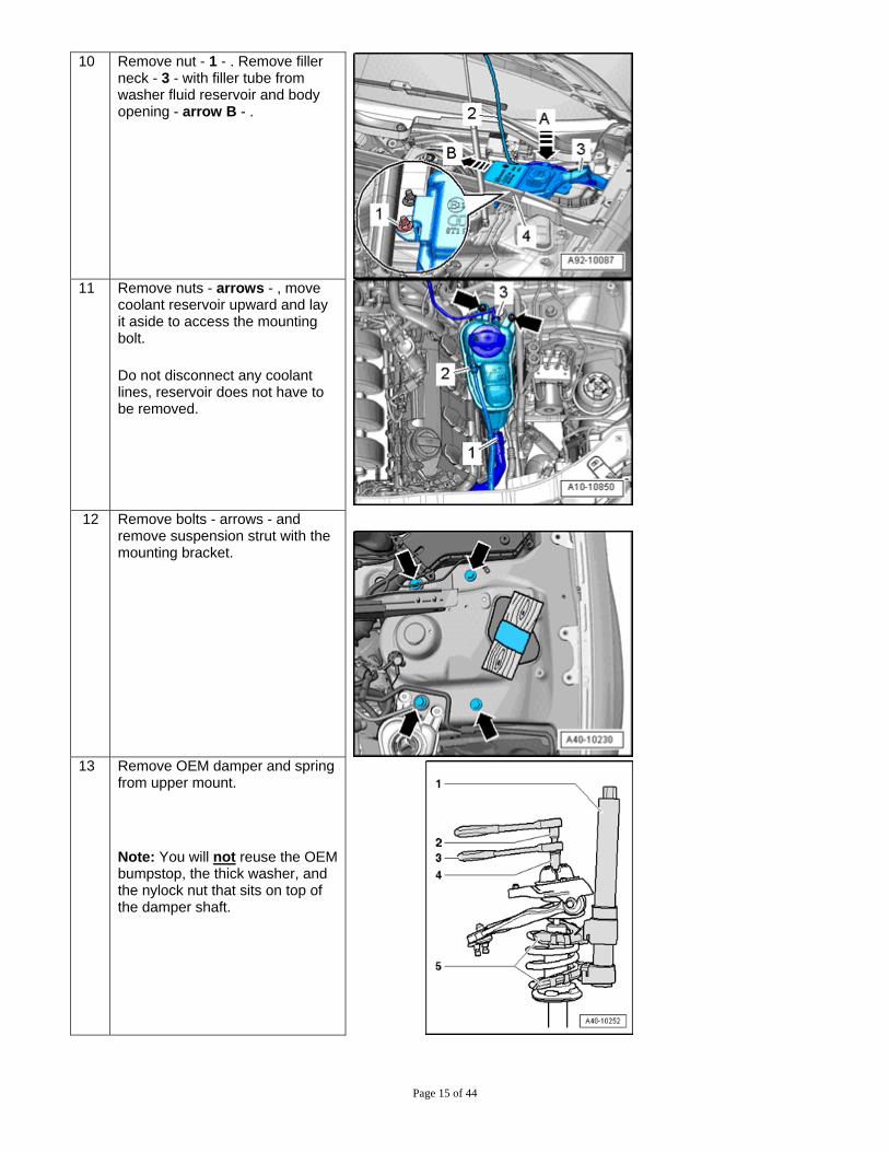
10 Remove nut - 1 - . Remove filler neck - 3 - with filler tube from washer fluid reservoir and body opening - arrow B - .
11 Remove nuts - arrows - , move
coolant reservoir upward and lay it aside to access the mounting bolt.
Do not disconnect any coolant lines, reservoir does not have to be removed.
12 Remove bolts - arrows - and
remove suspension strut with the mounting bracket.
13 Remove OEM damper and spring
from upper mount.
Note: You will not reuse the OEM bumpstop, the thick washer, and the nylock nut that sits on top of the damper shaft.

Page 16 of 44
14 Remove swaged aluminum upper
spring seat retainer. Use a small chisel and hammer to bend over the swaged lip. A die grinder can also be used to grind the lip off of the center of the aluminum retainer.
15 Install spring with delrin upper mount onto the STaSIS damper.
Install upper cradle and rubber upper mount onto the damper assembly. Hold upper damper pin in between the cradle and mount with a wrench while tightening the nut for the damper pin to the rubber upper mount. Tighten nylock nut to 37 ft-lbs.
CAUTION – DO NOT grab the damper shaft with any tools while tightening the nylock nut.
NOTE – Spring assembly will be loose at preset perch height. This is normal and will get loaded once installed in the vehicle.
Page 17 of 44
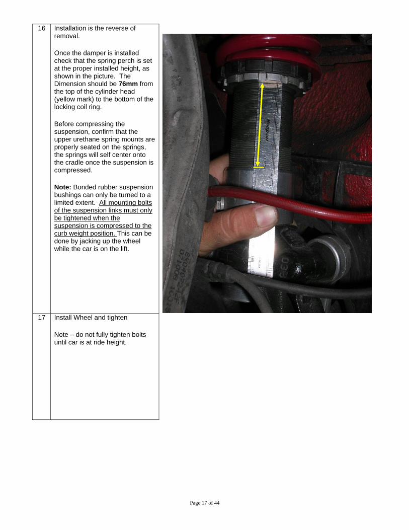
16 Installation is the reverse of removal.
Once the damper is installed check that the spring perch is set at the proper installed height, as shown in the picture. The Dimension should be 76mm from the top of the cylinder head (yellow mark) to the bottom of the locking coil ring.
Before compressing the suspension, confirm that the upper urethane spring mounts are properly seated on the springs, the springs will self center onto the cradle once the suspension is compressed.
Note: Bonded rubber suspension bushings can only be turned to a limited extent. All mounting bolts of the suspension links must only be tightened when the suspension is compressed to the curb weight position. This can be done by jacking up the wheel while the car is on the lift.
17 Install Wheel and tighten
Note – do not fully tighten bolts until car is at ride height.

Page 18 of 44
Rear Removal
1 Remove wheel
2 Remove upper damper bolts. Then remove lower damper bolt and remove damper. Note: Discard the lower bolt cover. It will not be reused. *S4 Vehicle* Remove ride sensor lever arm to prevent damage. Located on rear control arm, driver’s side. *Make sure to reconnect during installation*
Page 19 of 44
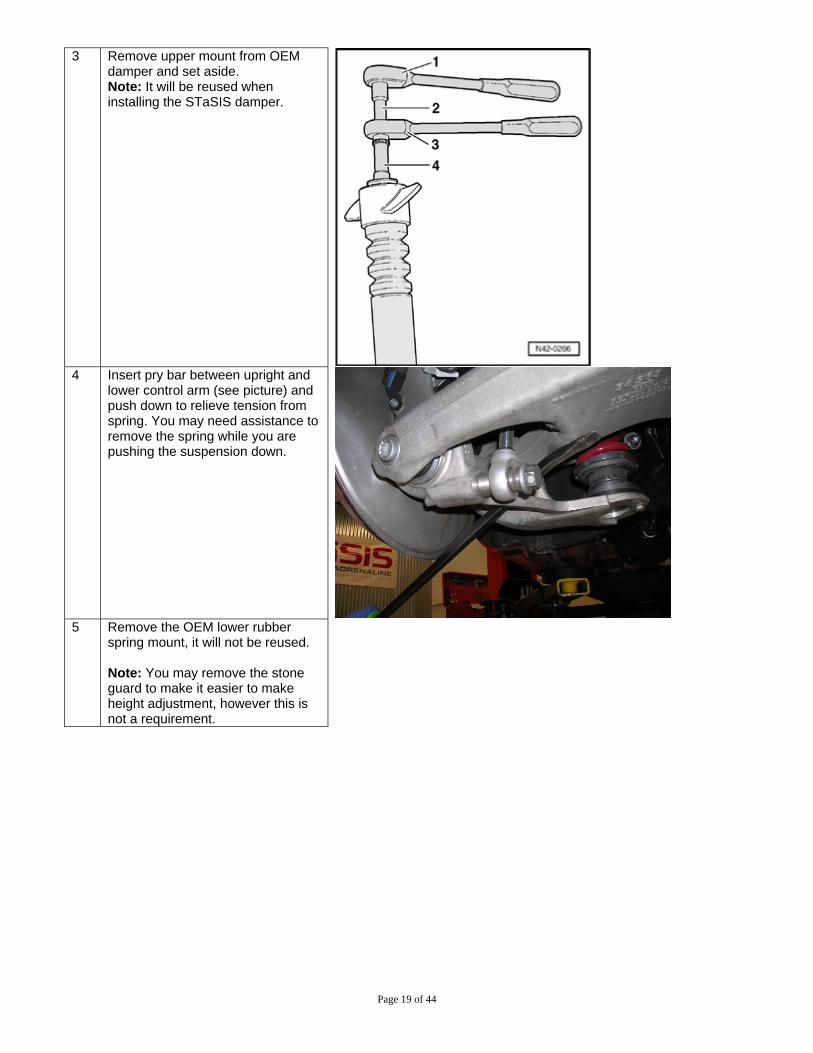
3 Remove upper mount from OEM damper and set aside. Note: It will be reused when installing the STaSIS damper.
4 Insert pry bar between upright and
lower control arm (see picture) and push down to relieve tension from spring. You may need assistance to remove the spring while you are pushing the suspension down.
5 Remove the OEM lower rubber
spring mount, it will not be reused. Note: You may remove the stone guard to make it easier to make height adjustment, however this is not a requirement.

Page 20 of 44
Rear Installation 6 Install STaSIS lower spring perch
onto lower control arm and secure with the supplied bolt. Note: Check that the perch is set to the proper installed height. As shown in the picture below. The dimension should be 64mm from the bottom of the rear spring perch spacer to the spring seat (yellow mark). DO NOT include the UHMWPE washer thickness in the measurement.

Page 21 of 44
7 Install STaSIS spring and OEM upper rubber mount. Earlier kits include a tender spring with a coupler on top of the main spring. Note: You will have to use a pry bar in the same manner used to remove the OEM spring
8 Install the OEM upper damper
mount onto the STaSIS damper. Grab cylinder head with a wrench and tighten nylock nut to 37 ft-lbs.
9 Install damper assembly and torque to: Upper bolt: 37 ft-lbs Lower bolt: 111 ft-lb, longer bolt spacer goes against the upright, short spacer between the bolt head and damper end eye. Note – Bonded rubber suspension bushings can only be turned to a limited extent. The mounting bolts of the suspension links must only be tightened when the suspension is compressed to the curb weight position. This can be done by jacking up the wheel while the car is on the lift.
Page 22 of 44
10 Install wheels and tighten. Lower the car onto its wheels and torque all wheel lug bolts to the recommended torque. Check ride height – See next page STaSIS recommended ride heights- Front - 13 1/2” from the center of the wheel to the fender lip Rear - 13 3/8” from the center of the wheel to the fender lip Note: Check wheel alignment after suspension installation
Rev. 1 11/2/08
Page 23 of 44
STaSIS Signature Line Ride Height Adjustment
Ride height inspection and adjustment procedure:
1. After completing installation of the kit, set the vehicle on the ground and drive the car around the block to settle the suspension. To take ride height measurements MAKE SURE THE VEHICLE IS PARKED ON A LEVEL SURFACE. VERY IMPORTANT!
2. Measure the ride height of the vehicle at four points for future reference. Measure from the center of the
wheels to the bottom of the fender lip. 3. If you are pleased with this ride height then you are done, save the measurements for future reference.
If not continue to step 4. 4. Calculate the difference between the actual ride height and the ride height you would like the car to sit
at for the right front wheel. For optimum handling we recommend this be done with the driver in the car and ¾ of a tank of fuel. We recommend that the distance between the center of the wheels and the bottom of the fender lip is not set below 13.0 inches. The suspension is operating too close to its maximum bump travel and handling can be negatively impacted.
5. The ratio between the front shock body motion and wheel motion is about 0.65 to 1 and the rear is 0.80
to 1. This means that the wheel travels about 1 inch for every 0.65 inches of shock body travel on the front and 0.80 inches of spring travel on the rear. Therefore, for example, if you wanted to lower the car ½ inch from its current ride height at the right front wheel, then you would have to lower the lower spring perch on the right front shock body by ½ x 0.65 = 0.32 inches. The rear motion ratio is calculated the same way.
6. Repeat steps 4 & 5 for the left front, left rear and right rear wheels. 7. Armed with the data from steps 4,5 & 6, securely jack the car up and place it on four jack stands.
Remove the wheels if necessary to reach the lower spring perches. For the front dampers, loosen the lower perch lock ring and thread the lower perch up or down by the amount you have calculated in step 5. The rear spring perch does not have a locking ring and can be turned freely. Record the location of the perches so you can have it as a future reference if needed. Once the desired height is attained, tighten the locking perch against the spring perch.
8. Place the wheels back on the car and lower it to the ground. Drive the car around the block or press up
and down on the car 3 or 4 times at each of the four wheels to settle the suspension before you make any measurements. Make sure the car is in the exact same location as before and go to step 2.

Page 24 of 44
STaSIS Signature Line Maintenance Instructions Custom Valved Ohlins Threaded Steel Dampers The STASIS Coil Over kit is designed to provide superior service for the lifetime of your vehicle. As this suspension system is a race car derived kit with high performance components, routine maintenance is required to insure the optimal operation of your suspension system. We recommend the following steps are performed bi-annually, preferably before and after the winter season. Vehicles that are exposed to more abusive environments, such as sea salt, road salt or dirt roads may necessitate more frequent maintenance.
1. Securely support the vehicle on four jack stands and remove the road wheels. 2. Clean the threaded portion of the damper with a non metallic brush using soap and water. 3. We recommend lowering or raising the lower spring perch to allow access to clean the
threaded portion of the damper that is covered by the perches. 4. Lubricate the threaded portion of the damper with “Boeshield T9” lubricant-protectant or a
similar wax based lubricant. 5. Return the perches to their original location and tighten the locking perches. Spray
protectant on the remaining components of the damper assembly.
6. Check the rear spherical bearings and verify that they are properly lubricated.
7. Service your dampers with STaSIS every 2 years to maintain product warranty and optimal functionality.
8. If you have any questions about this, please call STaSIS at 707-935-9700.
Secure the road wheels and return the vehicle to the ground. Watch that the springs seat properly on the spring perches

Page 25 of 44
A4/S4 Suspension *When performing complete Sig.Series package, removing OEM exhaust prior to ARB highly recommended* Rear Anti-Roll Bar
Applications List Qty Description Part Number 1 A4 B8 STaSIS Rear ARB 24 mm SA15.2100.00 1 S4 B8 STaSIS Rear ARB 28mm SA15.3100.00 Tools Required
Description 13mm Socket 10mm Triple Square Socket 16mm Socket 16mm Box End Wrench Medium Prybar
Torque Values
ARB Mounting Bracket Bolts, 10mm Triple Square 29 N m Lower Drop Link Bolts 54 N m Upper Drop Link Bolts 54 N m Chassis Cross Brace Bolts 54 N m Exhaust Muffler Hanger Nuts 20 N m

Page 26 of 44
1 Before removing any parts, jack the vehicle up, and place the vehicle on four stable jack stands or use
a professional vehicle lift.
2 Support the exhaust and remove the two exhaust muffler hanger nuts (one per side), 13mm socket.
3 Gently pry the two center exhaust rubber hangers of off the exhaust. Use a lubricant (i.e. WD-40) if required.
Page 27 of 44
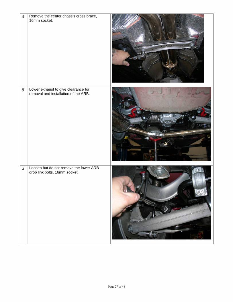
4 Remove the center chassis cross brace, 16mm socket.
5 Lower exhaust to give clearance for removal and installation of the ARB.
6 Loosen but do not remove the lower ARB drop link bolts, 16mm socket.

Page 28 of 44
7 Disconnect upper ARB drop link bolts from the ARB and rotate link to the side, 16mm end wrenches
8 Remove the bolts attaching the ARB brackets to the subframe (both sides), 10mm Triple Square Socket.
9 Remove the stock ARB from the car. Gently pry off the ARB mount brackets and rubber bushings (these will be re-used with the STaSIS ARB). OEM ARB bushings have enough flex to accommodate the STaSIS ARB.

Page 29 of 44
10 Install the OEM bushings and mounting brackets with a centered distance of 26 ¾” between the bolt centers of each clamp.
11 Install STaSIS ARB into vehicle. It may be necessary to deflect the upper control arm by gently using a pry bar as shown to facilitate the installation.
12 Once located, installation is the reverse of all removal steps. Make sure to locate drop link bolts into the ARB before tightening the ARB Mounting Bracket bolts. Torque all fasteners to the specifications shown. *NOTE*: After mounting to the vehicle, make sure your ARB is centered between the two clamps to avoid possible binding and interference with suspension components during vehicle operation.

Page 30 of 44
A4/S4 Center Differential Installation Parts List:
Qty Description Part Number 1 High Bias Torsen DL01.0012.00
Special Tools Required
Qty Description Part Number 1 Drip Tray VAG 1306 1 Torque Wrench VAG 1331
Removal
1 Loosen quick-release fasteners - 2 and 3 - and remove rear noise insulation.
2 Disconnect exhaust system at clamps – arrows
Disengage rear section of exhaust system at rubber mounting and remove

Page 31 of 44
3 If installed, remove heat shield for drive shaft - arrows
4 Remove bolts – arrows – at transmission/drive shaft
flange. Slide drive shaft together toward rear final drive. The constant velocity joints can be moved axially.
5 Secure drive shaft to selector rod. Place drip tray VAG
G1306 under transmission. Support transmission using engine/transmission jack V.A.G 1383 A with transmission support T10337 attached.
6 Remove tunnel crossmember bolts - arrows -
Page 32 of 44
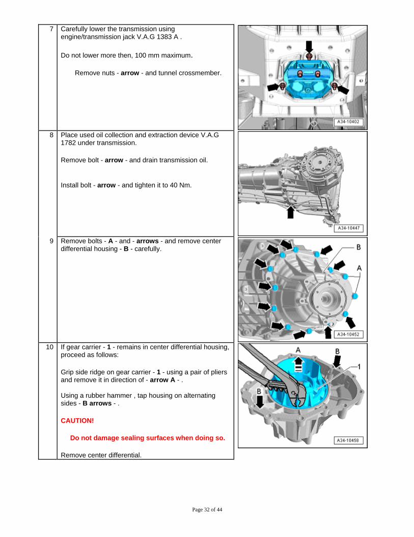
7 Carefully lower the transmission using engine/transmission jack V.A.G 1383 A .
Do not lower more then, 100 mm maximum.
Remove nuts - arrow - and tunnel crossmember.
8 Place used oil collection and extraction device V.A.G
1782 under transmission.
Remove bolt - arrow - and drain transmission oil.
Install bolt - arrow - and tighten it to 40 Nm.
9 Remove bolts - A - and - arrows - and remove center
differential housing - B - carefully.
10 If gear carrier - 1 - remains in center differential housing,
proceed as follows:
Grip side ridge on gear carrier - 1 - using a pair of pliers and remove it in direction of - arrow A - . Using a rubber hammer , tap housing on alternating sides - B arrows - .
CAUTION!
Do not damage sealing surfaces when doing so.
Remove center differential.

Page 33 of 44
Installation
11 Install gear carrier on transmission as follows:
Installation position: The tab on gear carrier - arrow A - must be in opening in transmission housing - arrow B - .
12 Clean both joint surfaces in the housing.
Position center differential - 2 - over gear carrier - 1 - . Insert plate spring - 5 - , adjustment shim(s) - 4 - and spring - 3 - in center differential housing - 6 - . Plate spring installation location - 5 - : The camber on inner diameter - arrow - faces toward center differential housing - 6 - . Apply sealing paste AMV 188 001 02 evenly and not too thick. Then position center differential housing - 6 - on transmission.
13 Press center differential housing - B - on until it makes contact with transmission housing and hold it securely.
Install and tighten new bolts - arrows - . Tightening specification: 7 ft-lbs plus an additional 90 degree turn. Tighten bolts - A - Tightening specification: 18 ft-lbs.
Page 34 of 44
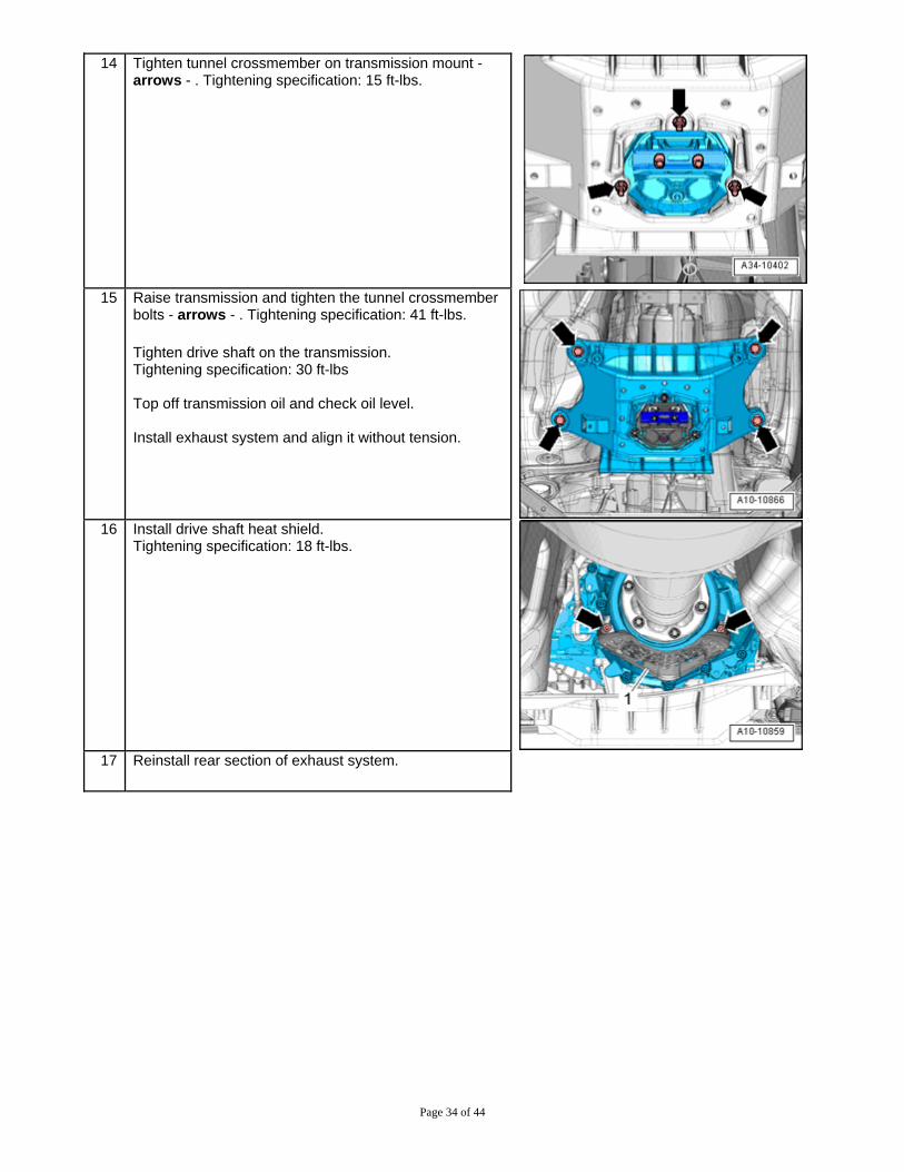
14 Tighten tunnel crossmember on transmission mount - arrows - . Tightening specification: 15 ft-lbs.
15 Raise transmission and tighten the tunnel crossmember
bolts - arrows - . Tightening specification: 41 ft-lbs.
Tighten drive shaft on the transmission. Tightening specification: 30 ft-lbs Top off transmission oil and check oil level. Install exhaust system and align it without tension.
16 Install drive shaft heat shield.
Tightening specification: 18 ft-lbs.
17 Reinstall rear section of exhaust system.

Page 35 of 44
A4/S4 Exhaust Exhaust Kit Installation
Applications Qty Description Part Number 1 A4 Sig Series Twin Tip Exhaust EX05.A4B8.00 1 S4 Sig Series Quad Tip Exhaust, Low SE221-E10-01-00 1 S4 Sig Series Quad Tip Exhaust, High SE221-E10-02-00 Instructions
1 Place vehicle in secure position. Remove factory exhaust system up to the catalytic converter assembly. Leave rubber hangers in position.
2 Using a 10mm socket, remove the 3 plastic nuts holding the right side cavity cover. *S4 Vehicle* Steps 2-6 do not apply
3 Remove the push clip retainer in the rear right corner of the cavity cover. Remove the cover from the vehicle.

Page 36 of 44
4 Gently pull to remove the stock rear valence.
5 Install the supplied exhaust hanger onto the right
side muffler.
6 Install the supplied heat shield for the right side of
the vehicle using the speed nuts pictured above.

Page 37 of 44
7 Make sure there is adequate clearance between the heat shield and the sway bar. The heat shield should be tight against the chassis. If not, gently bend the heat shield. Attach new valence by gently pressing on tabs across the bumper. Attention: S-line vehicles must trim the new valence to the provided template to avoid interference during operation.
8 Install mid pipe and driver’s side muffler into position. Slipping it into the mid-pipe and secure loose enough for adjustment
9
Remove hardware from adjustment bracket. Be sure to keep them for reinstallation.
10
Install passenger side into position. Slipping it into the mid-pipe and secure loose enough for adjustment.
11
Reinstall hardware for adjustable bracket and tighten flanges and bracket with mufflers aligned and spaced evenly. Confirm the side-side distances are equal (x). Loosen nut (arrow) on adjustable bracket and align muffler as necessary. Torque nut to 23 Nm (17 ft-lb)
12 Loosen factory hangers at rear of muffler with 13mm
wrench. Using the slots in these hangers and the adjustable bracket, position tips in centers of bumper cutouts.
13 Test drive and check for rattles. Re-adjust as necessary to provide proper clearance.

Page 38 of 44
A4/S4 Brakes
Optional STaSIS Monobloc Brake Kit
Parts List: Qty Description Part Number
1 Rotor Alcon 370X32 RH BR01.1006.00 1 Rotor Alcon 370X32 LH BR01.1007.00 4 SHCS M12x1.750x60 12.9 Blue HA01.1206.75 1 Caliper Alcon Mono6 RH Trailing BR03.1002.00 1 Caliper Alcon Mono6 LH Trailing BR03.1003.00 2 Bracket B8 14.5 Mono6 BR04.1400.00 1 Line Kit Audi Front Alcon BR20.1007.00 2 Brake Line Stop Washer BR20.1008.00 1 Project Mµ NS Pad Set BP01.6001.00 1 Fluid Motul 5.1 BP99.1000.00
Installation Guidelines
Please follow these guidelines when installing the front brake kit. • Torque all fasteners to specification. Do not use an impact wrench. • The rotors are side-specific, rotational direction is labeled. Open portion of crescents face toward the
direction of rotation. • The rotors have been dynamically balanced by machining the outer edge. Flat spots along the outer
diameter are normal and will not affect the performance of the rotor. • Tighten hydraulic connections with a line wrench. • Bleed brakes properly to assure proper brake operation; the use of a power bleeder is
recommended. • Ensure all ABS sensor and Pad wear sensor plugs are reconnected. • Proper pad bedding is essential to proper brake operation. • Initially drive the car with low braking force to check brake operation; then follow all steps listed in the
bedding process outlined at the end of this instruction manual. • During bedding do not thermally shock the rotors with aggressive braking before the rotors have come
up to temperature. Cracks on new rotors can form due to thermal shock. Gradually increase brake pressures as instructed in the bedding procedure.
• After bedding brakes re-torque wheel nuts to proper torque specifications. • If vibration occurs during normal usage, check for abnormal pad wear deposits on the rotor. Double
check all fasteners and repeat the bedding process 2-3 cycles until the pad deposits on the rotor becomes uniform.
• If the vehicle is driven in adverse weather conditions, STaSIS Engineering recommends annual cleaning and inspection of the rotor crescents. A common source of vibration can be attributed to dirt completely filling in the crescents on the inboard side of the rotors which in turn will not allow the pad to function properly.
• Brake rotor wall thickness wear limit is 1.0 mm per side of rotor. Rotor face runout limit +/- 0.010 in, when taking measurement make sure rotor is tightened down to the hub at all 5 bolt locations.
Page 39 of 44
Instructions
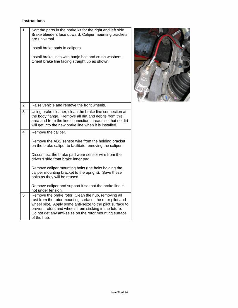
1 Sort the parts in the brake kit for the right and left side.
Brake bleeders face upward. Caliper mounting brackets are universal. Install brake pads in calipers. Install brake lines with banjo bolt and crush washers. Orient brake line facing straight up as shown.
2 Raise vehicle and remove the front wheels. 3 Using brake cleaner, clean the brake line connection at
the body flange. Remove all dirt and debris from this area and from the line connection threads so that no dirt will get into the new brake line when it is installed.
4 Remove the caliper. Remove the ABS sensor wire from the holding bracket on the brake caliper to facilitate removing the caliper. Disconnect the brake pad wear sensor wire from the driver’s side front brake inner pad. Remove caliper mounting bolts (the bolts holding the caliper mounting bracket to the upright). Save these bolts as they will be reused. Remove caliper and support it so that the brake line is not under tension.
5 Remove the brake rotor. Clean the hub, removing all rust from the rotor mounting surface, the rotor pilot and wheel pilot. Apply some anti-seize to the pilot surface to prevent rotors and wheels from sticking in the future. Do not get any anti-seize on the rotor mounting surface of the hub.

Page 40 of 44
6 Install caliper mounting brackets using the stock mounting bolts and torque to 92 ft-lb. The bracket will mount to the outside face of the upright with the angle flange going over the mounting ears in the upright. The OEM bolts will fit through the upright from the backside and thread into the bracket.
7 Install the new rotors making sure they are free of dirt
and grease. Tighten the rotor retaining bolt to 48 in-lbs.
8 Place the caliper with the brake pads installed onto the
caliper mounting bracket and install the caliper mounting bolts M12 x 1.75 x 60 and torque to 70 ft-lb. If the caliper will not go over the rotor because the pads are too close together, push the pads back using a pad spreader. Note: When rotating, the rotor must always pass the small caliper piston first. Therefore in a trailing caliper application like we have here the small caliper piston will be at the bottom of the caliper. The purpose is to insure even pad wear.
Page 41 of 44
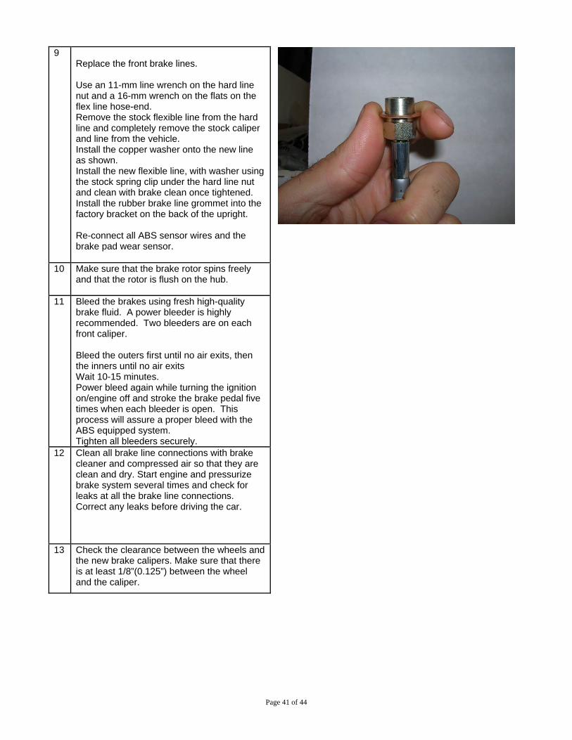
9
Replace the front brake lines. Use an 11-mm line wrench on the hard line nut and a 16-mm wrench on the flats on the flex line hose-end. Remove the stock flexible line from the hard line and completely remove the stock caliper and line from the vehicle. Install the copper washer onto the new line as shown. Install the new flexible line, with washer using the stock spring clip under the hard line nut and clean with brake clean once tightened. Install the rubber brake line grommet into the factory bracket on the back of the upright. Re-connect all ABS sensor wires and the brake pad wear sensor.
10 Make sure that the brake rotor spins freely and that the rotor is flush on the hub.
11 Bleed the brakes using fresh high-quality brake fluid. A power bleeder is highly recommended. Two bleeders are on each front caliper. Bleed the outers first until no air exits, then the inners until no air exits Wait 10-15 minutes. Power bleed again while turning the ignition on/engine off and stroke the brake pedal five times when each bleeder is open. This process will assure a proper bleed with the ABS equipped system. Tighten all bleeders securely.
12 Clean all brake line connections with brake cleaner and compressed air so that they are clean and dry. Start engine and pressurize brake system several times and check for leaks at all the brake line connections. Correct any leaks before driving the car.
13 Check the clearance between the wheels and the new brake calipers. Make sure that there is at least 1/8”(0.125”) between the wheel and the caliper.
Page 42 of 44
14 Verify that all bolts are tight and torque the wheel lug bolts.
15 Test drive the car using the brakes gently.
16 WARNING: Do not aggressively test the brakes until they are properly bedded.
17 Bed the pads and rotors. See the Bedding Procedure attached to these installation instructions. After brakes are fully bedded recheck wheel lug bolt torque.
Page 43 of 44
STaSIS Bedding Procedure After installing new pads, rotors, or both, it is necessary to properly bed the pad to the rotor before using the brakes to their full capacity. What is bedding? Bedding is the process of depositing a layer of pad material (often called the transfer layer or transfer film) onto the surface of the rotor. Brake rotors used on OEM style brake systems do not require this transfer layer as the braking system is relying on friction between the pad and the rotor material to slow the vehicle down. On STaSIS rotors, the bond between the pad and the transfer layer is much stronger and the frictional characteristics of the pad/transfer layer interface are far better than those of a pad/rotor interface. It is therefore crucial to bed pads properly to ensure the reliability, performance, and longevity of your STaSIS/ALCON brake system. When should I bed pads and rotors? Bedding is recommended whenever you install new pads or rotors, or experience vibrations while braking. • For new pads and rotors, bedding allows the manufacturing resins in the pads to burn off
slowly to avoid uneven deposits or pad glazing. Bedding also allows the rotors to relieve any thermal stresses incurred during the manufacturing process.
• Vibrations felt through the brake pedal are most commonly a result of uneven pad deposition, which is remedied by re-bedding the existing components.
Bedding Process
1. Upon initial installation do not bed the rotors immediately. Drive the vehicle with normal to light braking for 1-2 days to allow the pad and rotor surfaces to conform better before bedding in at higher temperatures.
2. Find a suitable road. You will need a relatively straight road with minimal traffic where you can safely (and legally!) reach speeds up to 65 MPH.
3. Once the car has been driven with light braking for a few miles to bring the rotors up to the proper operating temperature, bring the car up to approximately 65 MPH. Gently apply constant pressure (about 10%) to the brakes, bringing the car down to about 20 MPH.
4. Accelerate briskly back to 65 MPH. Apply the brakes again, however this time use more force (about 20%).
5. Repeat steps 2 and 3, each successive time applying more pressure. Your last two brake applications should engage or nearly engage the ABS system.
6. Do not immediately stop the vehicle with your foot on the brakes after step 5, the concentrated heat from the pad sitting on a non-rotating rotor will warp the rotor. Drive vehicle using absolutely minimal brake application to cool the rotors to ambient temperature (freeway driving).
7. Once the system has cooled, repeat the entire process. After completing two heat cycles on the rotors, check the rotors for an even, slightly hazy coating (often with a slight blue tint). Any spotting or blotches indicate uneven pad deposition. Repeat the process until the rotor surface is even.
Page 44 of 44
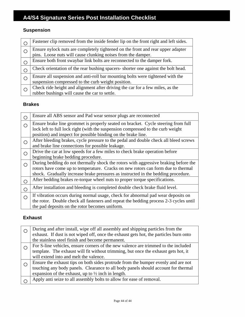
A4/S4 Signature Series Post Installation Checklist Suspension o Fastener clip removed from the inside fender lip on the front right and left sides.
o Ensure nylock nuts are completely tightened on the front and rear upper adapter pins. Loose nuts will cause clunking noises from the damper.
o Ensure both front swaybar link bolts are reconnected to the damper fork.
o Check orientation of the rear bushing spacers- shorter one against the bolt head.
o Ensure all suspension and anti-roll bar mounting bolts were tightened with the suspension compressed to the curb weight position.
o Check ride height and alignment after driving the car for a few miles, as the rubber bushings will cause the car to settle.
Brakes
o Ensure all ABS sensor and Pad wear sensor plugs are reconnected
o Ensure brake line grommet is properly seated on bracket. Cycle steering from full lock left to full lock right (with the suspension compressed to the curb weight position) and inspect for possible binding on the brake line.
o After bleeding brakes, cycle pressure to the pedal and double check all bleed screws and brake line connections for possible leakage.
o Drive the car at low speeds for a few miles to check brake operation before beginning brake bedding procedure.
o During bedding do not thermally shock the rotors with aggressive braking before the rotors have come up to temperature. Cracks on new rotors can form due to thermal shock. Gradually increase brake pressures as instructed in the bedding procedure.
o After bedding brakes re-torque wheel nuts to proper torque specifications.
o After installation and bleeding is completed double check brake fluid level.
o If vibration occurs during normal usage, check for abnormal pad wear deposits on the rotor. Double check all fasteners and repeat the bedding process 2-3 cycles until the pad deposits on the rotor becomes uniform.
Exhaust o During and after install, wipe off all assembly and shipping particles from the
exhaust. If dust is not wiped off, once the exhaust gets hot, the particles burn onto the stainless steel finish and become permanent.
o For S-line vehicles, ensure corners of the new valence are trimmed to the included template. The exhaust will fit without trimming, but once the exhaust gets hot, it will extend into and melt the valence.
o Ensure the exhaust tips on both sides protrude from the bumper evenly and are not touching any body panels. Clearance to all body panels should account for thermal expansion of the exhaust, up to ½ inch in length.
o Apply anti seize to all assembly bolts to allow for ease of removal.


