MINI Cooper Hardtop 2002-2006 (R50) IMPORTANT ! • Read this Installation Guide completely before beginning the installation. • This is a guide – your vehicle may vary. ALWAYS check behind panels & components before drilling, cutting, or screwing into any part of a vehicle. Contents INSTALLATION GUIDE MODEL 1101S SUBWOOFER SYSTEM DIY SKILL LEVEL REQUIRED 3 5 INSTALLATION DIFFICULTY OUT OF 4 INSTALLATION TIME Hrs PRINTING INSTRUCTIONS: LANDSCAPE ORIENTATION, FIT TO PAGE OVERVIEW .................................................................................... 2 BEFORE YOU BEGIN! ................................................................... 2 WHAT’S IN THE BOX .................................................................... 3 TOOLS YOU WILL NEED .............................................................. 5 INSTALLATION: A. PREP ThE VEhICLE .................................................................. 6 B. RUN ThE POwER & GROUND wIRES .......................................... 7 C. SIGNAL wIRING ....................................................................... 8 D. MOUNT AMPLIFIER & CONNECT wIRING ...................................... 9 E. INSTALL ThE ENCLOSURE MOUNTS............................................ 10 F. PREP & INSTALL ThE ENCLOSURE ............................................ 11 G. TESTING & RECOMMENDED INITIAL SETTINGS ............................. 12 TIPS & TUNING ........................................................................... 13 TROUBLESHOOTING ................................................................. 13
• LAyOUT & IDENTIFy ALL COMPONENTS & hARDwARE. USE ExTRA CARE TO BE CERTAIN yOU hAVE PROPERLy IDENTIFIED EACh SCREw.
• INSTALLATION VARIES DEPENDING ON whEThER yOUR VEhICLE IS FACTO-Ry-EqUIPPED wITh ThE STANDARD 6 SPEAkER OR UPGRADED hk AUDIO SySTEM. MAkE SURE yOU hAVE PROPERLy IDENTIFIED yOUR VEhICLE. INSTALLATION STEPS ARE LABELED AS FOLLOwS:
- [6SPk ONLy] APPLy ONLy TO STANDARD 6 SPEAkER VEhCILES
- [hk ONLy] APPLy ONLy TO hk EqUIPPED VEhICLE
- IF NO NOTATION IS LISTED, ThE INSTALLATION STEP APPLIES TO ALL VEhICLES
• NOTE: EACh kIT MAy APPLy TO MORE ThAN ONE VEhICLE MODEL AND MAy INCLUDE ExTRA ITEMS. DISREGARD ANy ITEMS NOT MENTIONED IN ThE INSTRUCTIONS FOR yOUR VEhICLE.
• NOTE: DO NOT DEVIATE FROM ThESE INSTRUCTIONS OR ThE INCLUDED hARDwARE. EVERy COMPONENT OF ThIS SySTEM hAS BEEN CAREFULLy SELECTED By OUR ENGINEERS. FAILURE TO FOLLOw ThESE INSTRUC-TIONS OR CORRECTLy IDENTIFy AND USE ThE SUPPLIED hARDwARE MAy RESULT IN POOR PERFORMANCE AND POSSIBLE SAFETy hAzARDS.
Overview Before You BeginThIS GUIDE COVERS INSTALLATION OF ThE MINI COOPER MODEL 1101S SUB-
wOOFER SySTEM IN 2002-2006 MINI COOPER hARDTOPS (R50).
ThE SUBwOOFER ENCLOSURE INSTALLS IN ThE FLOOR OF ThE LUGGAGE COMPART-MENT (AkA ThE “BOOT”). ThE SUB AMPLIFIER INSTALLS IN ThE SMALL COMPART-MENT ON ThE DRIVER’S SIDE OF ThE BOOT AND MOUNTS TO AN INCLUDED ALUMINUM BRACkET. A REMOTE LEVEL CONTROL INSTALLS AT ThE DASh FOR ON-ThE-FLy SUBwOOFER ADjUSTMENT.
POwER & GROUND wIRES ARE PRE-TERMINATED AND ASSEMBLED AND ARE RUN DOwN ThE LEFT SIDE OF ThE VEhICLE. ThE AUDIO INPUT SIGNAL AND TURN-ON SIGNAL ARE TAPPED AT ThE BACk OF ThE RADIO (OR AT ThE AMP FOR hk-EqUIPPED VEhI-CLES). ThE SIGNAL wIRING IS RUN TO ThE DASh-MOUNTED REMOTE LEVEL CONTROL AND ThEN BACk TO ThE SUB AMPLIFIER.
V. SubwooferencloSureHardwareKIt1. NEUTRIk SPEAk-ON CONNECTOR w/GASkET2. #10 x 2.5” PAN hEAD SCREw (3) 3. #10 x 1.5” PAN hEAD SCREw (6)4. ¼” x 1” hEx hEAD BOLT5. #10 x 1” BLACk PAN hEAD SCREw (8)6. #10 x ¾” PAN hEAD SCREw (8)7. #4 x ¾” BLACk PAN hEAD SCREw (4)8. ThREADED INSERT (3)9. ThREADED INSERT INSTALLATION wRENCh
VII. aMplIfIerMountIngKIt(rearMount)27. AMPLIFIER MOUNTING BRACkET28. M6 FLANGE NUT (1) & wAShERS (2)29. SCREw GROMMET30. #8 x ½” TRUSS hEAD SCREw (1)31. #6 x 3/8” PAN hEAD SCREw (4)
2
11
98
10
21
3534302976543
26
27
14
13
*SELECT COMPONENTS FOR IDENTIFICATION - NOT ALL COMPONENTS ShOwN BELOw
Detach straps (1) and slide the parcel shelf out of guides (2).
Remove the luggage compartment floor panel. The floor panel will not be placed back into the vehicle and can be stored.
A. PREPTHEVEHICLE
7. detacHrIgHt&leftSIderearpanel
[HK ONLY]
Depress latches (1) and remove cover.
Remove screws (2) and (3).
Repeat this step for the LEFT side. The left side does not need to be removed (see next step), it just needs to be loosened to facilitate access for mounting the amplifier.
8. reMoVerIgHtSIderearpanel
[HK ONLY]
Detach the rear seat belt at the bottom with a Torx T-50. Pull the panel towards the interior of the vehicle releasing the friction clips (2). Then lift up on the panel, freeing it from the metal retaining clips attached along the top of the panel (1).
Reinstallation is the reverse of the above. Guide the panel onto the retaining clips (1) first. You may find it easier to bend the clips open slightly.
5. reMoVerearSeat(part2)The outside of each seat back has a pin that sits in a “T” shaped keyway. Rotate each seat back up to about 45 degrees and pull toward the center of the vehicle to release.
4. reMoVerearSeat(part1)Fold down the rear seat backs. Remove the 10mm bolt at the base of the center attachment of the rear seat backs. Pry the catch up. Lift up on the seat back to release.
3. reMoVerearSIll
Locate the three expansion rivets (1) at the lower edge of the rear sill. Pry out the center-pin of each expansion rivet with a flat screwdriver or panel removal tool. Pry out the base of the expansion rivet. Pull the bottom of the rear sill toward the front of the vehicle to clear the metal “D” rings. Pull the whole panel upwards, releasing the friction clips (2). Keep the center-pins with the expansion rivets to avoid confusion with similar pins removed in later steps.
2. reMoVefloorpanel
Pry the center pin (1) out of the two retaining clips. Remove the floor panel (2).
6. reMoVerearSeatbottoM
Pull up firmly on the front of the edge of the rear seat bottom to release. The back of the seat is attached by wire rod loops hooked into down-ward facing tabs. Press down on the back edge of the seat bottom and pull forward to release .
Remove the Torx T-50 bolt. Remove the metal rod that secures the bottom of the seat belt.
15. pulldowntHeKneebolSter
Pull in and down firmly on the top of the Knee Bolster (the panel under the steering wheel) to release the top. Lift each outer edge to release the hinges at the bottom. Remove and set aside.
16. fISHpowerwIretHrougHfIrewall
Locate the wire pass-thru grommet in the upper left of the area behind the knee bolster (just above and left of the top of the clutch pedal, if present). Feed your electrician’s fish tape through this grommet and into the engine compartment. Locate the fish tape in the engine compartment (see item (1) from step 14). Tape the end of the power wire to the fish tape and pull it into the cabin.
14. routetHepowerwIretotHebattery
Open the bonnet. Remove the battery cover (2). Determine the routing of the power wire from the battery to the pass-thru grommet in the firewall. On some vehicles you may need to drill a small hole in the plastic bulkhead around the battery compartment to pass the wire thru.
12. reMoVeleftdoorSIlltrIM(part3)[Seat shown removed for clarity]
Remove the door seal over the entire length of the right door sill by lifting it up and off. Pull Door Sill Panel (2) inward, releasing clips (3). This requires a firm pull at each of the clip locations. Remove the small trim piece (1) by pulling it toward the rear of the vehicle, releasing spring clip.
11. reMoVeleftdoorSIlltrIM(part2)Remove the expansion rivet (1) from the front of the Door Sill (in the footwell area). Pull firmly inward all along the
B. POWER&GROUNDWIRING10. reMoVeleftdoorSIlltrIM(part1)The top of the Left Rear Interior Panel locks over the Left Door Sill Trim and must be released to remove the Door Sill. Pull inward firmly on the bottom of the front of the Left Rear Panel, releasing the friction clips (1) for just this portion. It is not necessary
13. reMoVetHerIgHtdoorSIlltrIMRepeat the previous three steps for the Right Side of the vehicle.
Mount the PAC LC1 Remote Level Control in the location of your choice with the self-adhesive 3M Dual-lock or the screws provided with the Level Con-trol. Our preference is under the bottom of the center console as shown.
NOTE: If using the 3M Dual-lock, wipe both surfaces with one of the Alcohol Prep Pads before applying.
20. InputSIgnalwIrIngoVerVIew
The input signal connection is made by tapping into the signal at the factory head unit. The signal is routed through the remote volume control, and then down the right side of the vehicle and then over to the subwoofer amplifier. The connection for the remote turn on lead for the ARC amplifier is also made at the head unit, and runs down the left side of the vehicle with the power wire and to the amp.
19. attacHgroundwIre&runwIreStoaMp
Pull up the carpet behind the driver’s seat and locate the Common Ground. Remove the nut with a 10mm socket and connect the ring terminal of the Ground Wire here.
Insert your fish tape from the rear quarter panel until it exits by the ground wire connection. Fish both the Power & Ground wires to the small compartment on the driver’s side of the boot.
18. feedpowerwIrealongdoorSIll
Run the Power Wire along the drivers side door sill area, behind the right side rear interior panel.
17. attacHbatterylead Remove the auxiliary nut on the battery post and attach the power wire. Do not install the fuse into the holder yet.
Secure any loose sections of wire with wire ties. Pull any remaining slack wire into the cabin.
C.SIGNALWIRING[6SPKVEHICLESONLY]
22. routeSIgnalwIreS
Connect the RCA-to-Stripped Wire Pigtails to the “IN” leads on the Remote Level Control and RCA Interconnects to the “OUT”. Route these wires up around the console, under and behind the glove box, along the passenger side door sill, and behind the right rear interior panel to the h/k amplifier area.
23. IdentIfySIgnalwIreS
Unplug the X10266 connector of the h/k amplfier (A18). Locate the wires identified in the chart below. Each set of ++ and -- wires should be a twisted pair. Confirm the wire by checking the pin number, which can be observed by removing the gray and black sections from the housing by lifting/releasing the retaining notch at the open end of the housing. If you are not sure you have identified the correct wires contact us before proceeding!
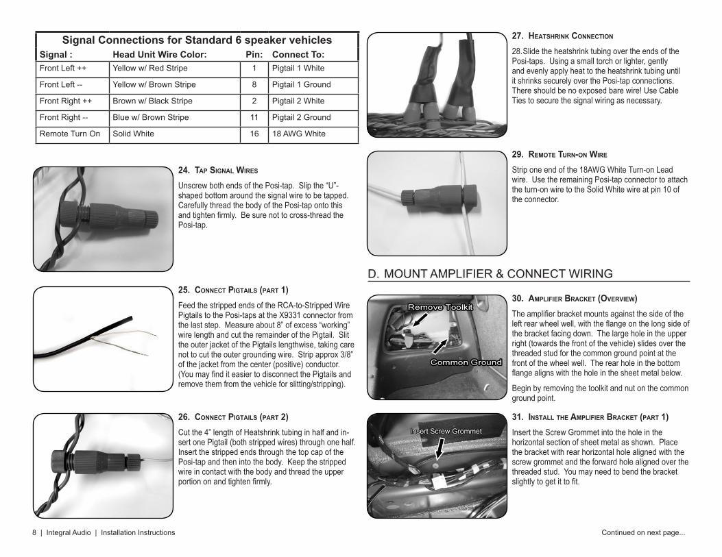
Unscrew both ends of the Posi-tap. Slip the “U”-shaped bottom around the signal wire to be tapped. Carefully thread the body of the Posi-tap onto this and tighten firmly. Be sure not to cross-thread the Posi-tap.
30. aMplIfIerbracKet(oVerVIew)The amplifier bracket mounts against the side of the left rear wheel well, with the flange on the long side of the bracket facing down. The large hole in the upper right (towards the front of the vehicle) slides over the threaded stud for the common ground point at the front of the wheel well. The rear hole in the bottom flange aligns with the hole in the sheet metal below.
Begin by removing the toolkit and nut on the common ground point.
31. InStalltHeaMplIfIerbracKet(part1)Insert the Screw Grommet into the hole in the horizontal section of sheet metal as shown. Place the bracket with rear horizontal hole aligned with the screw grommet and the forward hole aligned over the threaded stud. You may need to bend the bracket slightly to get it to fit.
29. reMoteturn-onwIre
Strip one end of the 18AWG White Turn-on Lead wire. Use the remaining Posi-tap connector to attach the turn-on wire to the Solid White wire at pin 10 of the connector.
27. HeatSHrInKconnectIon
28. Slide the heatshrink tubing over the ends of the Posi-taps. Using a small torch or lighter, gently and evenly apply heat to the heatshrink tubing until it shrinks securely over the Posi-tap connections. There should be no exposed bare wire! Use Cable Ties to secure the signal wiring as necessary.
26. connectpIgtaIlS(part2)Cut the 4” length of Heatshrink tubing in half and in-sert one Pigtail (both stripped wires) through one half. Insert the stripped ends through the top cap of the Posi-tap and then into the body. Keep the stripped wire in contact with the body and thread the upper portion on and tighten firmly.
25. connectpIgtaIlS(part1)Feed the stripped ends of the RCA-to-Stripped Wire Pigtails to the Posi-taps at the X9331 connector from the last step. Measure about 8” of excess “working” wire length and cut the remainder of the Pigtail. Slit the outer jacket of the Pigtails lengthwise, taking care not to cut the outer grounding wire. Strip approx 3/8” of the jacket from the center (positive) conductor. (You may find it easier to disconnect the Pigtails and remove them from the vehicle for slitting/stripping).
D.MOUNTAMPLIFIER&CONNECTWIRING
Signal Connections for Standard 6 speaker vehiclesSignal : Head Unit Wire Color: Pin: Connect To:FrontLeft++ Yelloww/RedStripe 1 Pigtail1White
32. InStalltHeaMplIfIerbracKet(part2)Leaving the Common Ground connection in place, put the two 6mm washers over the Common Ground threaded stud, then the bracket, and finally the 6mm nut. Tighten the nut using a deep 10mm socket.
Fasten the #8 X ½” Screw through the rear hole in the bracket and into the Screw Grommet. Prevent the Grommet from turning with a straight pick or small screwdriver inserted into the split in the side.
39. tHreadedInSertS(oVerVIew)Self-Sealing Threaded Inserts are used to secure the enclosure to the vehicle. It is important that you follow these installation steps carefully and com-pletely. An extra Insert is provided in case you run into trouble.
40. InStalltHreadedInSertS(part1)Using a 7/16” bit (NOT a ½” bit!), drill holes in the 2 positions marked on the boot floor. Do not let the drill bit penetrate more than ¼” through the sheet metal. You may find it helpful to use a cut-to-length wood block as a stop for the drill. It is important to drill the holes EXACTLY where they were marked.
Remove any metal burrs - the hole must have clean edges.
37. attacHtHeMountIngbracKetS
Remove the enclosure. Align the brackets with the lines marked in the previous step. Place the bottom of the bracket approx 1/4” above the bottom edge of the enclosure. Attach the bracket with the #10 x ¾” Pan Head Screws. Replace the enclosure and confirm hole locations are correctly market. Remove the enclosure.
36. MarKforbracKetplaceMent
Temporarily replace the Rear Sill. Center the subwoofer enclosure in the boot. Place a Mount-ing Bracket on either side with the single-hole side centered over the indicated raised area of the boot floor. Keep the hole at least 3/8” away from the edges of the raised area of the sheet metal. Cut a notch the carpet edge if necessary. Mark the center with a marker or center punch. Mark the location of the vertical sides of the bracket against the enclosure with a pencil.
35. MountaMplIfIer
Mount the Amplifier to the bracket using the (4) #6 x 3/8” screws. Use the pre-drilled hole locations. Place the wire bundle (that was loosened earlier) in the gap between the amp and the sheet metal.
34. aMplIfIerconnectIonS
Connect the Power, Ground, and Remote Turn-on Lead wires to the amplifier. Connect the RCA Inter-connects. Set the Signal input selector on the amp to “RCA”. Connect the Speaker Wire to the Amp using the “bridged” connection locations. Refer to the Amp manual if needed.
33. SpeaKerwIre
Cut 2 feet from the length of 16AWG Speaker Cable and set aside. Split and strip the ends of the remain-ing 6 feet. Attach the positive wire to the L+ connec-tor on the amp, negative to R-. Attach the Banana Plugs to the other end by loosening the 3mm Allen screw, inserting the wire, and tightening the screw.
Run the Speaker Wire from the amp area to the cen-ter of the vehicle, routing it along & under the carpet trim at the front of the boot area.
41. InStalltHreadedInSertS(part2)Using a utility knife, carefully trim the PVC jacket out of the center of the Self-Sealing Threaded Inserts as shown. Insert the 1” Hex Bolt through the Installation Tool. Then thread the 1” Hex Bolt into the Threaded Insert. Be sure the “nubs” on the Installation Tool face the top of the Threaded Insert. These “nubs” are what grip the Insert and prevent it from turning during installation.
47. InStalltHeencloSure
Place the enclosure back into the boot. Connect the Banana Plugs to the Terminal Cup. Insert the Rosette Thumbscrews through the Mounting Brackets and screw into the Threaded Inserts. If you made a mistake drilling the holes and the Thumbscrews do not line up, drill larger holes in the mounting brackets.
NOTE: We recommend coating the threads of the Rosette Thumbscrews with grease to keep them operating smoothly and avoid corrosion.
48. HowtoreMoVetHefalSefloorThe False Floor Panel slides through the hatch opening and rests on the floor supports. To remove, simply push down on the edge near the rear seat backs, lift, and remove – clean, simple, easy!
46. MounttHefloorSupportS(part2)Mount the Stand-offs centered approx 2” in from the edges of the enclosure. Mark and drill 1/8” pilot holes. Attach the supports with the Screws and Cup Washers.
IMPORTANT: Tighten the screws until the metal Washer is recessed below the top of the Rubber Stand-off, providing a soft surface for the False Floor. If this is not done, the floor will rattle on the washer/screw-head.
45. MounttHefloorSupportS(part1)The floor supports are assembled with one Rubber Stand-off, one Cup Washer, and one #10 x 1.5” Pan Head Screw.
NOTE: The Stand-offs may have warped in transit. To get them to stack cleanly, wrap a few turns of electrical tape around them at the seam. Remove after installation.
44. MounttHeSpeaKer
Mount the speaker with the #10 x 1” Black Pan Head Screws. The speaker is snug fit! Tighten the screws in a “star” pattern, go slowly and take care not to strip them. Make sure the speaker flange is flush against the enclosure – the gasket on the back of the speaker flange MUST make an airtight seal.
43. wIrIng&terMInalcup
Split and strip the ends of the remaining 2 feet of 16AWG Speaker Cable. Crimp the (4) female ¼” Quick Disconnects to the wire and connect one pair the Terminal Cup and the other to the speaker, observing correct polarity. If possible, we strongly encourage soldering these connections instead of the (4) disconnects. Mount the Terminal Cup using the (4) #6 x ¾” Black Pan Head Screws.
42. InStalltHreadedInSertS(part3)Insert the Threaded Inserts into the holes drilled in the previous step. Keep the Insert vertical and keep the head of the Insert flush against the sheet metal and carefully tighten the bolt by hand with a wrench (do not use a powered tool of any kind) until you begin to feel resistance and the insert is secure. Take your time - do not over-tighten. Remove the 1” Hex bolt. If you have trouble with an Insert, you can remove it by partially unthreading the 1” Hex bolt and tapping it with a hammer.
To remove the enclosure, simply disconnect the speaker wire, unscrew the Rosette Thumbscrews, and remove.
WARNING: Do not allow the Banana Plug connec-tors to short (touch each other) while the system is energized.
52. recoMMendedInItIalaMplIfIerSettIngS
Gain: 20% (see ARC manual)
Output: LOW (low-pass crossover)
Crossover: 80 Hz
Bass Boost: 0
Input: RCA In (button should be OUT)
Factory Radio Bass Level: -2
50. reconnecttHebattery&InStallfuSeReconnect the Battery Negative Terminal and Install one of the 30 amp AGU fuses in the fuse block. A spare fuse is included.
G.TESTING&RECOMMENDEDINITIALSETTINGS
51. teStforcorrectoperatIon
Turn on the system and check for correct operation. Once you have confirmed that everything is operating correctly, reinstall all panels and trim removed during the installation. Use the provided electrical tape and cable ties to wrap and secure wiring bundles and har-nesses as necessary.
TEST!
12|IntegralAudio|InstallationInstructions
• TUNING & PERFORMANCE: The factory audio system is “tuned” to provide exaggerated bass at around 60Hz, giving the temporary illusion of better bass performance. Unfortunately the factory speakers aren’t capable of producing this exaggerated level of bass without creating distortion that affects the other frequencies the speaker is asked to produce. The Integral Audio subwoofer sys-tem allows the correction of this factory “tuning”. Because the subwoofer system has an independent volume control, the “Bass” EQ setting on the headunit can be lowered. This reduces the exaggerated bass level being sent to the factory speakers and eliminates the greatest source of distortion in the system, improving the transient response of the factory speakers. The recommended initial settings listed earlier will give nearly flat frequency response in the sub-bass region.
• SIGNAL SOURCE QUALITY: A poor quality signal will always sound poor no matter how good an audio system is. If you are using MP3s or home-burned CDs it is critical that you understand the limitations and impacts of digital compression methods. MP3s at less than 256kbps will have noticeable loss of quality. Satel-lite radio is also compressed and will have similar quality issues. Non-commer-cially obtained music (especially downloaded via P2P file-sharing) recordings are often re-mixed by third parties and will have been compressed in an unknown and uncontrolled manner. If you want good quality sound, use only commercial CDs or MP3s compressed at 256kbps or 320kbps.
• FACTORY RADIO SETTINGS: Please note that the settings (Bass, Treble, Fade, Balance, AUX input level, etc.) are stored on the Key FOB & are specific to the Source (Radio, CD, AUX). You will need to edit and save the settings for each source and each FOB to have consistent sound.
Having Trouble? The best thing to do is contact us at [email protected] or via the phone number listed on the receipt that was emailed to you. We’ll get you fixed up!