060-00786611/16 in (17 mm)
9/16 in (14 mm)
11/16 in (17 mm)
Installation guide
Pressure switch KP 15A
060R
9752
060R
9752
© Danfoss | DCS (jmn) | 2016.11 DKRCI.PI.C00.C3.22 | 520H11519 | 1
CAUTION:Do not mount the control in a position where dirt, sediment or oil will affect the operation of the control.
t1 min .: -40 °F (-40 °C)t1 max.: 65 °C (149 °F)
Ambient temperatures / Mounting requirements Test pressure (Ptest)
Connections
Mounting
Cutting ring
ptest max. 20 bar (285 psig)PS/MWP
ptest max. 35 bar (510 psig)PS/MWP
Refrigerants:R717, R22, R134a, R404A, R407A, R407C, R407F, R422B, R422D, R438A, R448A, R449A, R450A, R452A, R507A, R513AFor complete list of approved refrigerants, go to http://products.danfoss.com/all-products/
Cable entry1/2 in int. thread accepts 1/2 in NPT or NPS
© Danfoss | DCS (jmn) | 2016.112 | 520H11519 | DKRCI.PI.C00.C3.22
CAUTION: The mounting panel must be plane to avoid damage of control.
Enclosure
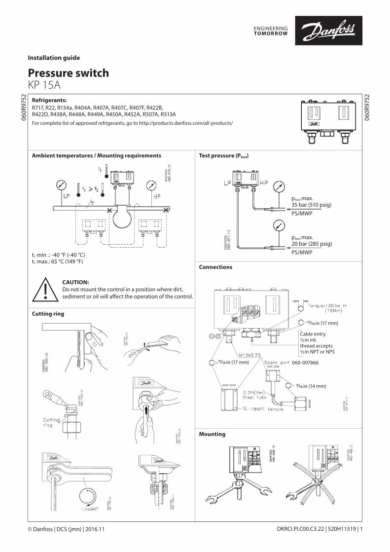
WiringAll wiring should conform to the NationalElectrical Code and local regulations.
SPDTControls with low pressure (LP) signal
Terminal block
Controls with low pressure (LP) and high pressure (HP) signal)
Terminal block
CAUTION:Use terminal screws furnished in the contact block.Use tightening torque 20 lb. in (2.3 Nm).Use copper wire only.
Low pressure (LP) side:A-C close on LP riseA-C open on LP drop
High pressure (HP) side:A-C open on HP riseA-C close on HP drop
LP signal option:A-B close on LP drop
See label for current wiring inside cover.
CAUTION: Use terminal screws furnished in the contact block.Use tightening torque 20 lb. in (2.3 Nm).Use copper wire only.
Low pressure (LP) side:A-C close on LP riseA-C open on LP drop
High pressure (HP) side:A-C open on HP riseA-C close on HP drop
LP signal option:A-B close on LP drop
HP signal option:A-D close on HP rise
Function
Contact load ratings
See label inside cover
120 V AC 16 FLA, 96 LRA
240 V AC 8 FLA, 48 LRA
240 V DC 12 W pilot duty
CAUTION:Disconnect power supply before wiring connections are made or service to avoid possible electrical shock or damage to equipment. Do never touch live parts with your fingers or with any tool.
= Load
= Signal option
= Bellows movement on pressure rise
= Bellows movement on pressure drop
Note!
max 1/8 in (3 mm)
B: Enclosure ~NEMA1 C: Enclosure ~NEMA2A: 8 – 32 UNC (M4)
Reset options
© Danfoss | DCS (jmn) | 2016.11 DKRCI.PI.C00.C3.22 | 520H11519 | 3
LP man. LP auto. LP auto. LP man.
HP man. HP man. HP auto. HP auto.
Manual tripping (Electrical contacts/wiring test)
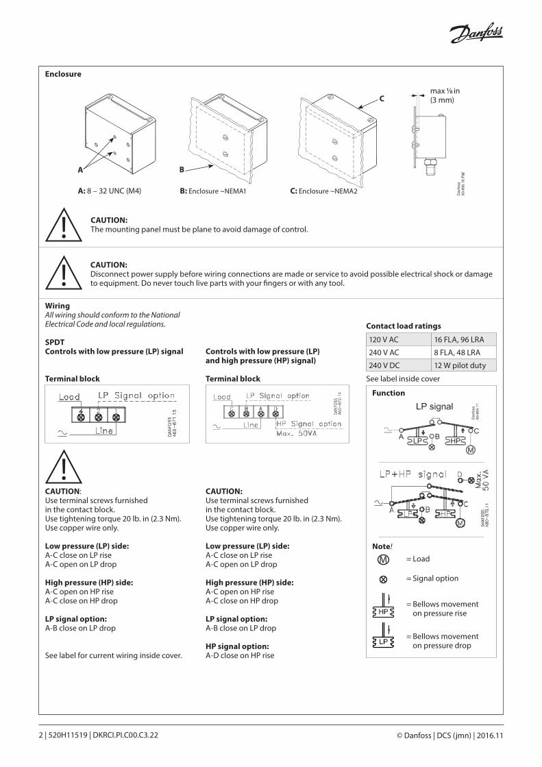
Note:On controls with LP and/or HP man. reset, push corresponding LP and/or HP man. reset knob during tripping.
Trip:use FINGERS ONLY! (Do NOT use screwdriver)
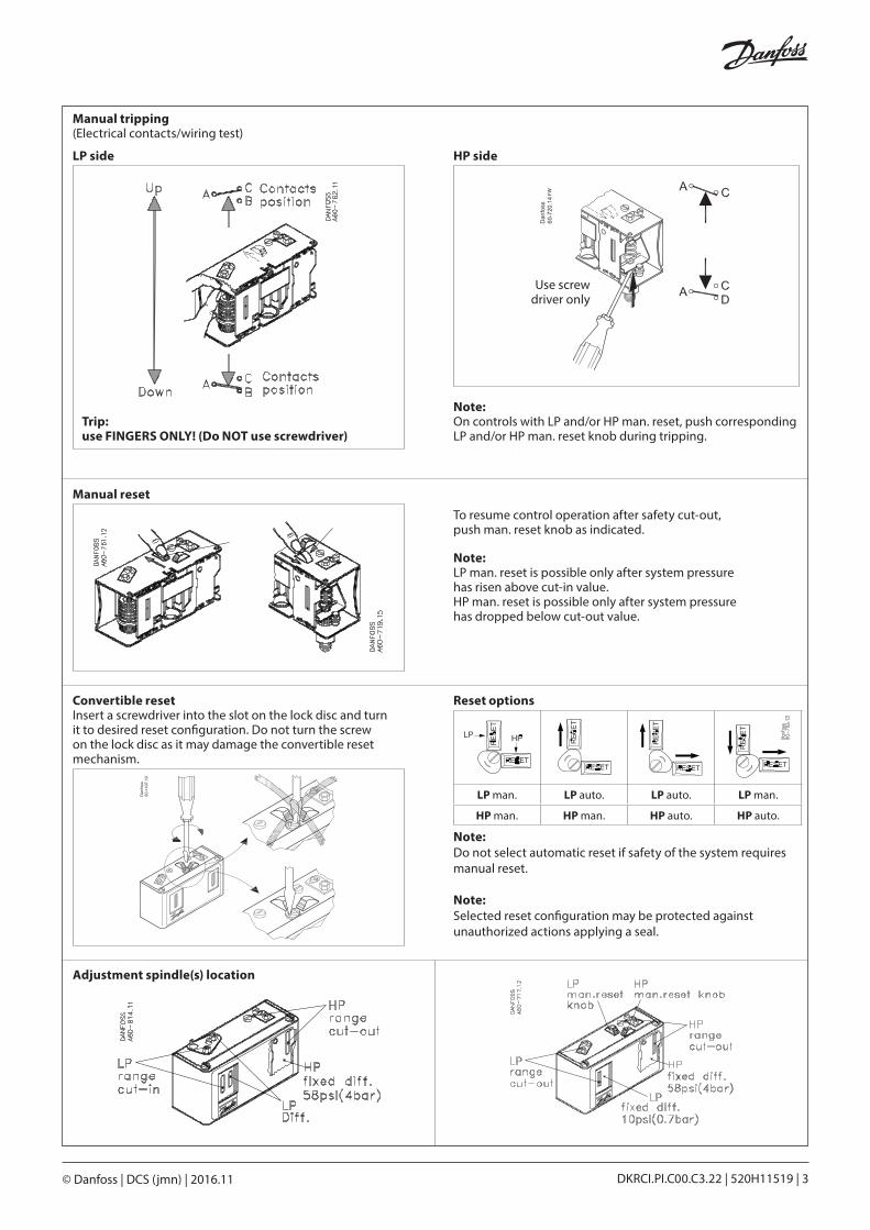
To resume control operation after safety cut-out, push man. reset knob as indicated.
Note:LP man. reset is possible only after system pressure has risen above cut-in value. HP man. reset is possible only after system pressure has dropped below cut-out value.
Manual reset
Convertible resetInsert a screwdriver into the slot on the lock disc and turn it to desired reset configuration. Do not turn the screw on the lock disc as it may damage the convertible reset mechanism.
Note: Do not select automatic reset if safety of the system requires manual reset.
Note: Selected reset configuration may be protected against unauthorized actions applying a seal.
LP side HP side
Adjustment spindle(s) location
Use screw driver only
© Danfoss | DCS (jmn) | 2016.114 | 520H11519 | DKRCI.PI.C00.C3.22
Adjustment
Note:Remove lockplate before adjustment.Replace lockplate after adjustment (if desired).
1. Adjust range spindle to desired CUT-IN value.
2. Adjust differential spindle to desired DIFFERENTIAL (DIFF.) value.
CUT-IN minus DIFFERENTIAL equals CUT-OUT
Example: Example:
CUT-IN equals CUT-OUT plus DIFFERENTIAL
CUT-OUT minus DIFFERENTIAL equals CUT-IN
1. Adjust range spindle to desired CUT-IN value.
2. DIFFRENTIAL (DIFF.) is fixed. Value printed on scale plate.
1. Adjust range spindle to desired CUT-OUT value.
2. DIFFRENTIAL (DIFF.) is fixed. Value printed on scale plate.
CUT-IN – DIFF. = CUT-OUT30 psig – 10 psi = 20 psig(2.1 bar) (0.7 bar) (1.4 bar)
CUT-OUT + DIFF. = CUT-IN12 psig + 10 psi = 22 psig(0.8 bar) (0.7 bar) (1.5 bar)
Example:CUT-OUT – DIFF. = CUT-IN203 psig – 58 psi = 145 psig(14 bar) (4 bar) (10 bar)
Low pressure (LP) side setting High pressure (HP) side settingSetting
KP 15A with LP auto. reset only KP 15A with HP auto./man. resetKP 15A with LP man. reset only KP 15A with convertible LP auto./man. reset
1
2
LP scale
1
2
LP scale
1
2
HP scale
10 psi (0.7 bar)/rev.
LP range LP differential
HP range
Increase 360°
Decrease360°
Increase 360°
Decrease360°
Decrease 360°
Increase360°
2 psi (0.15 bar)/rev.
33 psi (2.3 bar)/rev.
15/64 in (6 mm)
Lockplate