32
Ford Homes INSTALLATION GUIDE

Ford Homes
INSTALLATIONGUIDE

Weathertex® is Natural Australian hardwood timber Weatherboards and Architectural Panels. Whether you are seeking
external timber cladding for a renovation, extension, new home, or any commercial application, Weathertex weatherboards
and Architectural Panels offer an endless variety of external timber cladding solutions.
Weathertex puts sustainability and durability at the forefront of all our products. This ensures Weathertex delivers natural,
long-lasting, eco-friendly timber products to customers in Australia and around the world. Sustainably manufacturing a
highly durable product is an important part of Weathertex’s environmental impact. Made from environmentally sustainable
Australian hardwood, Weathertex is an all natural product with 97% hardwood and 3% natural wax with no chemical
additives.
Weathertex produces 100% of its product from sustainable new growth Australian hardwood in an ISO 9001 certified
process. All hardwood sourced for the production of Weathertex products comes from local new growth forests within
150 kilometres of the site. Weathertex has worked to ensure the raw timber for the production of its reconstituted natural
hardwood is sourced from local sawmill tailings, thinnings and sustainably managed forests. No old growth hardwood is
ever used, so the sourcing of our timber has minimal environmental impact and avoids depletion of our natural resources.
Introduction i
Weathertex Product Range 1 - 3
Weathertex Accessories Range 4 - 7
Fasteners and Gun Nailing 9
Product Information 10 - 12
General Requirements - All Products 12 - 15
Installation - Cavity Wall Systems 16 - 17
Installation - Weathertex Weatherboards 18 - 19
Installation - Weatherboards 20
Installation - Primelok Weatherboards 20
Installation - Selflok Weatherboards 21
Installation - Wall Shingles 21
Installation - Weathergroove 22
Installation - ExteriorBoard
and High ImpactBoard 23
Rubix Panel 24
Warranty 29
ISO 9001 Lic1864 SAI Global * Refer to Weathertex Manufacturer's Warranty Conditions
C O N T E N T S
I N T R O D U C T I O N

1
WEATHERTEX WEATHERBOARDS
Smooth and textured surface planks for lapped applications.
CLASSIC 3660mm x 200mm 3660mm x 300mm Smooth Ruff-Sawn
RUSTICATED3660mm x 200mm Smooth Ruff-Sawn
SELFLOK WEATHERBOARDS
Selflok Weatherboards are routed during manufacturing with a self-locking feature to allow each board to accurately align above one another, providing a clean and neat finish. Semi-concealed fixing in many wind areas is also possible. Ecogroove Woodsman available unprimed.
MILLWOOD3660mm x 300mm
OLD COLONIAL3660mm x 300mm
Smooth Ruff-Sawn Smooth
This product range is available in Australia. Outside of Australia, the product range is subject to availability. Please refer to your country's distributor for full range.
All Weathertex products have a thickness of 9.5mm and are primed as a standard feature. Some products as identified
below, are also available unprimed.
ECOGROOVE 150*3660mm x 300mm Smooth Woodsman
ECOGROOVE 300*3660mm x 300mm Smooth Woodsman
TEXWOOD3660mm x 300mm Smooth
* Refers to groove spacing.
W E AT H E RT E X P R O D U C T R A N G E
* Refers to groove spacing.
WALL SHINGLES
Regular vertically grooved Ruff-Sawn Weatherboards for overlapping shingles effect. Notched lower edge.Please note that wall shingles are supplied unprimed.
1195mm x 225mm

2
WEATHERGROOVE
Smooth, Ruff-Sawn or Woodsman surface texture with regular grooves. Rebated long edges combine with Weathergroove joiners to give a seamless vertical grooved wall. Woodsman available unprimed.
ExteriorBoard Sizes: 3660mm x 1220mm 2745mm x 1220mm 2440mm x 1220mm 1830mm x 1220mm 1220mm x 1220mm 915mm x 1220mm
EXTERIORBOARD AND HIGH IMPACTBOARD
ExteriorBoard and High ImpactBoard* offer the sought after modern express joint style by incorporating both vertical and horizontal express joins. Smooth and Woodsman surfaces are available, Woodsman is available unprimed .
WEATHERTEX ARCHITECTURAL PANELS
Smooth Ruff-Sawn Woodsman
Smooth Woodsman (3660 x 1220mm only) (MTO)
3660mm x 1196mm
3050mm x 1196mm
2745mm x 1196mm
2440mm x 1196mm
Groove Spacing 150mm
PRIMELOK WEATHERBOARDS
Smooth or textured profiled planks which feature the Primelok® aligning spline for increased accuracy, up to 20% faster installation than similar width lapped planks, and concealed fixing.
PRIMELOK 2003660mm x 200mm Smooth Ruff-Sawn Woodsman
BRAIDWOOD3660mm x 200mm Smooth Ruff-Sawn
FEDERATION3660mm x 170mm Smooth Ruff-Sawn
SHADOWOOD3660mm x 170mm Smooth
* High ImpactBoard is only available in smooth and sizes 3660mm x 1220mm and 2745mm x 1220mm.
* Refer to Weathertex Manufacturer's Warranty

3
RUBIX PANEL
Rubix Panel is a self-locking Architectural Panel designed to be joined on or off-stud.
NATURAL WOODSMAN
Weathertex Natural Woodsman range offers the characteristics and look of raw, undressed timber.
Weathertex’s Natural Woodsman (unprimed) surface provides unique appearance options, not achievable with the use of paints or pigmented finishes. When installed natural, the Natural Woodsman surface has the characteristics and look of raw, undressed timber. The natural surface can be oiled to maintain the look of fresh, brown timber or, alternatively it can be left untreated and allowed to age naturally. If allowed to age, the surface will weather and grey similar to other natural timber.
When purchasing and installing Weathertex Natural Woodsman, there are a number of things to keep in mind. Painting natural board with a pigmented finish will void all warranty. If a pigmented painted finish is to be applied, it must be onto Weathertex’s primed board. If the raw surface is to be oiled, a good quality, exterior grade timber oil such as a decking oil must be used. Weathertex recommends the appearance of a satin style oil. To maintain the fresh brown appearance and prevent aging and greying, the oil must be applied and maintained in accordance with the oil manufacturer’s instructions.
Weathertex's natural finished products are covered by a 7 year warranty not to rot, split or crack. Please refer to the Weathertex Manufacturer's Warranty for full details. If the board is to be installed untreated and allowed to weather naturally it may develop some small black spots on the surface. This is carbon which is inherent with the manufacturing process. These small black spots are not mould and will not affect the performance or longevity of the product.
Ecogroove 150 Natural
Ecogroove 300 Natural
Vgroove 300 Natural
ExteriorBoardNatural
(3660x1220mm only)
(MTO)
Weathergroove Natural
(3660x1196mm only)
Sizes: 1200mm x 1200mm 1200mm x 900mm
* Refer to Weathertex Manufacturer's Warranty
* Refer to Weathertex Manufacturer's Warranty

4
W E AT H E RT E X A C C E S S O R I E S R A N G E
PRODUCT LENGTH (mm) SUITED TO:
WEATHERBOARD JOINERS
200 Smooth or Ruff-Sawn
300 Smooth
Classic 200mm Weatherboards
Primelok Classic 200mm
Classic 300mm Weatherboards
RUSTICATED JOINERS
200 Smooth
200 Ruff-Sawn
Rusticated Smooth
Rusticated Ruff-Sawn
BRAIDWOOD JOINERS
200 Smooth
200 Ruff-Sawn
Primelok Braidwood Smooth
Primelok Braidwood Ruff-Sawn
FEDERATION JOINERS
170 Smooth
170 Ruff-Sawn
Primelok Federation Smooth
Primelok Federation Ruff-Sawn
SHADOWOOD JOINER
170 Smooth Primelok Shadowood Smooth
MILLWOOD JOINERS
300 Smooth
300 Ruff-Sawn
Selflok Millwood Smooth
Selflok Millwood Ruff-Sawn
OLD COLONIAL JOINER
300 Smooth Selflok Old Colonial Smooth
ECOGROOVE 150 JOINERS
300 Smooth
300 Woodsman
Selflok Ecogroove 150 Smooth
Selflok Ecogroove 150 Woodsman
ECOGROOVE 300 JOINERS
300 Smooth
300 Woodsman
Selflok Ecogroove 300 Smooth
Selflok Ecogroove 300 Woodsman
TEXWOOD JOINER
300 Smooth Selflok Texwood Smooth
SHINGLE JOINER
255 Weathertex Wall Shingles
170mm CONCEALED JOINER
170 Primelok 170 Weatherboards
200mm CONCEALED JOINER
200Classic 200mm Weatherboards
Primelok 200mm Weatherboards
300mm CONCEALED JOINER
300 Selflok 300mm Weatherboards
Ruff-Sawn

5
a
CAVITY WALL SYSTEM
SMALL CAVITY CLOSER
1830 a = 10Selflok Weatherboards, Weathergroove, ExteriorBoard, High ImpactBoard
LARGE CAVITY CLOSER
1830 a = 20Classic 200 and 300mm Weatherboards, Primelok Weatherboards
WEATHERTEX WRAPSHIELD
60m x 1350mm
All Weathertex Weatherboards and Architectural Panels when installed using the cavity fix method
CAVITY BATTENS 1220mm x 45mm All cavity constructions
W E AT H E RT E X A C C E S S O R I E S R A N G E
PRODUCT LENGTH (mm) SUITED TO:
PRIMELOK STARTER STRIP
1830All Weathertex Primelok Weatherboards
WEATHERGROOVE JOINERS
2440, 2745, 3050, 3660 Weathergroove
WEATHERGROOVE HORIZONTAL JOINERS
3660Weathergroove Smooth
Weathergroove Ruff-Sawn
PVC DEEP CHANNEL JOINER
3660 ExteriorBoard, High ImpactBoard
SMALL CORNER PLUG
Traditional Small External Aluminium Corner
LARGE CORNER PLUG
Traditional Large External Aluminium Corner

6
PRODUCT LENGTH (mm) DIMENSION SUITED TO:
LF ALUMINIUM CORNERS
SMALL INTERNAL LF ALUMINIUM CORNER
3660a = 27
b = 11
Selflok Weatherboards, Weathergroove, ExteriorBoard, High ImpactBoard
LARGE INTERNAL LF ALUMINIUM CORNER
3000a = 27
b = 21
Primelok Weatherboards, Rusticated, Classic Weatherboards
SMALL EXTERNAL LF ALUMINIUM CORNER
3660a = 27
b = 11
Selflok Weatherboards, Weathergroove, ExteriorBoard, High ImpactBoard
LARGE EXTERNAL LF ALUMINIUM CORNER
3000a = 27
b = 21
Primelok Weatherboards, Rusticated, Classic Weatherboards
SMALL WINDOW SURROUND
3660 a = 11Selflok Weatherboards, Weathergroove, ExteriorBoard, High ImpactBoard
LARGE WINDOW SURROUND
3660 a = 21Primelok Weatherboards, Rusticated, Classic Weatherboards
WINDOW CORNERSuited to finish corner junctions between window surrounds and LF corners
TRADITIONAL ALUMINIUM CORNERS
SMALL INTERNAL ALUMINIUM CORNER
3660a = 35
b = 11
Selflok Weatherboards, Weathergroove, ExteriorBoard, High ImpactBoard
LARGE INTERNAL ALUMINIUM CORNER
3000a = 35
b = 21
Primelok Weatherboards, Rusticated, Classic Weatherboards
SMALL EXTERNAL ALUMINIUM CORNER
3660a = 35
b = 11
Selflok Weatherboards, Weathergroove, ExteriorBoard, High ImpactBoard
LARGE EXTERNAL ALUMINIUM CORNER
3000a = 35
b = 21
Primelok Weatherboards, Rusticated, Classic Weatherboards
a
a
b
a
b
a
T R I M T E C A C C E S S O R I E S All Trimtec Accessories are made from anodised aluminium.
a
b
b
a
7
a
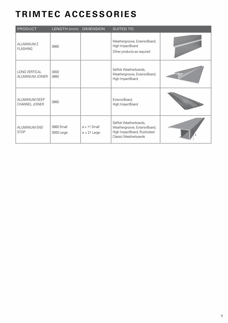
PRODUCT LENGTH (mm) DIMENSION SUITED TO:
ALUMINIUM Z FLASHING
3660Weathergroove, ExteriorBoard, High ImpactBoard
Other products as required
LONG VERTICAL ALUMINIUM JOINER
3000 3660
Selflok Weatherboards, Weathergroove, ExteriorBoard, High ImpactBoard
ALUMINIUM DEEP CHANNEL JOINER
3660ExteriorBoard, High ImpactBoard
ALUMINIUM END STOP
3660 Small
3000 Large
a = 11 Small
a = 21 Large
Selflok Weatherboards, Weathergroove, ExteriorBoard, High ImpactBoard, Rusticated Classic Weatherboards
T R I M T E C A C C E S S O R I E S

8
PAINTINGAnodised aluminium products must be coated with a suitable etch primer prior to painting, then normal commercially available top coats are able to be applied. Please contact the paint manufacturer for advice with these coating systems.
SURROUNDING MATERIALSCorrosion of aluminium may be exacerbated when contact is made with other metallic materials commonly used in construction.
Iron and Steel
Under humid conditions or areas close to the sea, the corrosion rate of aluminium may be accelerated when in contact with structural steel. To improve the performance of the aluminium product under these circumstances the steel should be coated.
Non-ferrous metals
Contact with copper and its alloys must also be avoided. Coating of these components is a satisfactory method of minimising this effect. Note: there are various timber products which have been treated with metallic compounds which may promote
corrosion under this system. Check this before using.
Non-metals
Contact with fresh concrete, mortars, plasters and fibre cement product should be avoided. These materials can release traces of alkaline materials which can cause a rapid corrosive staining of the aluminium product.
Damp or unseasoned timber may also cause a corrosive effect on the aluminium. This should be primed with a zinc chromate undercoat and sealed with a suitable top coat.
Adhesives should contain less than 0.1% chlorides.
Weathertex aluminium products have been anodised to provide a protective coating to the corrosive elements mentioned above.
MAINTENANCEStandard maintenance of exposed anodised aluminium corners should include periodic cleaning on at least a six month interval. In an industrial or marine location this frequency should increase because of the more severe environment. The following cleaning method is recommended.
use Methylated Spirits only. Minimise the contact time as much as possible and rinse thoroughly with fresh water.
STORAGE AND HANDLINGAnodised aluminium products should be stored in a dry and flat position away from any potentially corrosive materials. Timber or soft bearers at a distance no more than one metre apart should be used to support the product. Prolonged exposure to moisture will promote corrosion. This should be avoided and if experienced, immediately correct. The products are subject to damage or could damage other materials they are brought in contact with.
The edges and cut corners of the product may cause personal injury if brought into contact with the body. Wear glasses, gloves and protect skin where possible.
When cutting use appropriate personal protective equipment such as eye protection and avoid air borne metal fragments.
WEATHERTEX ANODISED ALUMINIUM

9
Gun nailing can be used as an alternative to specified hand driven nails. Generally, gun nails should have equivalent dimensions, head size, etc. to hand driven nails and must be galvanised or suitably coated for external use.
Suitable nail guns for the installation of Weathertex with the nails below includes, but may not be limited to:
Notes:
1. Installers using gun nailing must assure themselves that the appearance of the finished nailed Weathertex is suitable for the intended use. Generally, head sizes in excess of 6mm or T and D headshape nails may not produce a satisfactory finish on Selflok profiles or any other face fixed profiles eg. Weathergroove.
2. Nails MUST NOT be overdriven.This can reduce the holding capacity of the Weathertex. If the nailing depth cannot be adequately controlled when gun nailing, then it is preferable to under-drive and tap home with a hammer.
Supplier
DUO-FAST
For Softwood Frames
STANLEY BOSTITCH
D41260 D41510
PASLODE B20561VD41580
Nails
AC45R250-GAL AC50R250-GAL
DUO-FAST
For Hardwood Frames
STANLEY BOSTITCH
D41260 D41510
PASLODE B20565VD41600
AC45P250-GAL AC50P250-GAL
DUO-FAST
For Steel Frames (1.0 - 2.0mm for use in Geographic regions up to C2 only)
D41060
D42360
Description
45mm ring shank galvanised nail
50mm ring shank galvanised nail
45mm ring shank galvanised nail
50mm ring shank galvanised nail50mm ring shank D-HEAD galvanised nail
50mm ring shank stainless steel nail
45mm galvanised flat head nail (ring)
50mm galvanised flat head nail (ring)
45mm galvanised flat head nail
50mm galvanised flat head nailImpulse 50 x 2.87mm mechanical gal value pack
50mm screw shank stainless steel nail
32mm screw hardened dacrotised coil nail (Primelok, Selflok Profiles)
40mm screw hardened dacrotised coil nail (Classic lapped profiles)
For ease of installation, the following accessories are available through Weathertex stockists.
Notes:
1. All fasteners (nails and screws) must be galvanised or suitably coated to resist corrosion for external application. (Australian Standard AS 3566, Class 3 for screws).
2. Coastal locations can be very corrosive to fasteners, especially within distances of up to 500m from the sea. When installed in high corrosion zones, fasteners (nails and screws) must be made of materials appropriate to the desired life of the system and geographical location. Stainless Steel Nails and Class 4 Screws may be necessary in these zones. The advice of the fastener supplier should be sought.
3. The fasteners specified are minimum lengths required for each specific profile. If there is additional material between the Weathertex and the stud eg. packing, then the fastener length must be increased to provide the same fastener depth in the stud. See Cavity Fixing System Installation Instructions.
4. Nails MUST NOT be overdriven. This can reduce the holding capacity of the Weathertex.
Product
WEATHERTEX NAILS
Nails
FLAT HEAD NAILS
50 x 2.8mm countersunk head galvanised nail
Length (mm) Suited to:
Classic, Rusticated, Selflok, Shingles,Architectural Panels
50 x 2.8mm flat head galvanised nail All Primelok Weatherboards fixed onto softwood frames
60 x 2.8mm flat head galvanised nail For Weatherboards fixed onto softwood frames on cavity system
Product Suited to:
ITW Buildex Countersunk Rib Head Wingtek Screw (class 3) No.8 - 18x35mm
Screws
ITW Buildex FibreZips M5 - 18 x 30mm Countersunk Head
Fixing Weathertex Weatherboards and Architectural Panels to 1.0 - 2.5mm steel frames
For fixing Primelok, Selflok to steel frames 0.55 - 1.0mm thick
FA S T E N E R S
G U N N A I L I N G

10
WEATHERBOARDS Length mm Width mm Units per pack Contents m2
Classic 200 3660 197 144 103.8 Classic 300 3660 298 96 104.7 Rusticated 3660 197 144 103.8 Wall Shingles 1195 225 120 32.3
Millwood 3660 298 96 104.7 Old Colonial 3660 298 96 104.7 Ecogroove 150 3660 298 96 104.7Ecogroove 300 3660 298 96 104.7Texwood 3660 298 96 104.7Vgroove300 3660 298 96 104.7
DIMENSIONS AND PACKAGING
Thermal Insulation
R-Value of Total
Wall m2K/W
0.41.3
1.7
1.9
Insulation within wall
framing cavity
Nil
Double sided perforated reflective foil laminate (rfl) dished between studs
R1.5 bulk insulation between studs with breather foil or building paper under Weathertex
R1.8 bulk insulation between studs with breather foil or building paper under Weathertex
A wall consisting of 100mm x 50mm timber studs at 450mm centres, clad with Weathertex and lined internally with 5.5mm
transmission class can be increased to around STC 38-40 by using fibreglass or insulating board beneath the internal lining. Further STC data can be obtained in the “Weathertex and Fire” Factsheet.
Primelok 200 3660 197 144 103.8 Braidwood 3660 197 144 103.8 Federation 3660 170 168 104.5 Shadowood 3660 170 168 104.5
ExteriorBoard 12 x 4 3660 1220 24 107.2 9 x 4 2745 1220 24 80.37 8 x 4 2440 1220 24 71.4 6 x 4 1830 1220 24 53.6 4 x 4 1220 1220 48 71.4 4 x 3 1220 915 48 53.6 Rubix Panel4 x 4 1200 1200 48 69.14 x 3 1200 900 48 51.8Weathergroove 12 x 4 3660 1196 24 105.1 10 x 4 3050 1196 24 87.5 9 x 4 2745 1196 24 78.8 8 x 4 2440 1196 24 70.0 High ImpactBoard 12 x 4 3660 1220 24 107.2 9 x 4 2745 1220 24 80.37
PRIMELOK WEATHERBOARDS Length mm Width mm Units per pack Contents m2
ARCHITECTURAL PANELS Length mm Width mm Units per Contents m2
The thermal conductivity of Weathertex Weatherboard is 0.195W/mK. The thermal resistance R-value for the 9.5mm thickness is 0.05m2K/W.
ENERGY EFFICIENT HOUSING: is an initiative of the Australian Greenhouse Office and has been adopted by most States. House designs are assessed on a “star” rating principle (1 to 5 stars with 5 being the best). A Weathertex clad timber frame, internally lined and with various levels of insulation within the cavity will contribute to the achievement of energy efficiency.
THERMAL INSULATION
SOUND TRANSMISSION
Unit
kg/m3
kg/m2
MPaMPa%%
Typical Values
990*9.430
45007.50.25
DensityMass/Unit AreaModulus of RuptureModulus of ElasticityMoisture content ex millHygro-Expansivity = change in face dimensions over the range of 50% to 90% relative humidity
Property
PHYSICAL PROPERTIES
* Note: ImpactBoard has a guaranteed minimum density rating of 1025 kg/m3.
SELFLOK WEATHERBOARDS Length mm Width mm Units per pack Contents m2
P R O D U C T I N F O R M AT I O N

11
Weathertex direct fixing system has been subject to simulated wind suction forces at the Cyclone Testing Station, James Cook University, Townsville, Queensland, and in our own laboratory. When fixed as specified to timber studs the Weathertex profiles are suitable for use as shown. Wind classifications are as defined in AS4055-2006 “Wind Loads for Housing” and calculations use a local pressure factor for planks within 1200mm of the building corner. Other country standards are available on request.
HIGH WIND AREAS
Notes:
1. AS4055 -2006 Wind Classification N3 is equivalent to a maximum ultimate limit state design gust wind speed of 50m/s (NZS 3604:1999 classification very high). N4 and N5 are equivalent to 61m/s and 74m/s respectively.
2. If additional information is required, please call customer service on 1800 040 080.
Weathertex products are easy to cut and shape with a normal hand or power saw. Weathertex may be stacked two or three high for multiple cutting. Primelok Weatherboards should be cut individually to protect the aligning spline. Where required, edges may be trimmed with a smoothing plane or sandpaper. Holes are easily drilled with high speed drills or clean cutter bits.
CUTTING
Several Weathertex wall-cladding systems have been tested for use as structural bracing when fixed using the direct fix method of installation. The data given below are for use with limit state design criteria specified in Australian Standard AS 1684-1999, Residential timber-framed construction. Tie-down fixing and other construction detail must be as specified in AS 1684 for the appropriate wind classification.
WEATHERTEX AS STRUCTURAL BRACING
WEATHERTEX ARCHITECTURAL PANELSWeathertex Architectural Panels products when fixed directly as specified have the bracing capacity as shown. Minimum wall length to achieve the stated capacity is 900mm for on-stud construction and 2400mm for off-stud construction. In off-stud construction the length of the bracing wall used in the calculation must have a stud at each end of the wall to which the panels are nailed.
Weathertex Structural Bracing
Jointing
Method
On-stud
Nail Spacing
Top & Bottom Plates
(mm)
Nail Spacing Vertical
Sheet edges (mm)
Nail Spacing
Intermediate studs and
nogging (mm)
Bracing Capacity
(kN/m)
Type A Bracing Units
per 1.2m
wall length
Off-stud150150
150N/A
300300
4.01.8
1.60.7
Note: If additional bracing strength is required from an off-stud join please call customer service on 1800 040 080 for information.
Frame Product Highest wind Classification
Regions A & B Regions C & D
Fastener Fixing Stud
Centres(mm)
Unlined Wall Internally
Lined
Unlined Wall Internally
Lined
Weathertex Weatherboards
Timber 200mm Classic, Rusticated Weathertex
Nails
Traditional 450 N5 N5 C2 C3600 N4 N4 C1 C2
Selflok Weatherboards Weathertex
Nails
Traditional 450 N5 N5 C2 C3600 N4 N4 C1 C2
Semi-concealed 450 N4 N5 N/A N/A600 N3 N4 N/A N/A
DUO D31150 Semi-concealed 450 N4 N5 N/A C2Wall Shingles Weathertex
Nails
Traditional 450 N5 N5 C2 C3600 N2 N2 N/A N/A
Steel Selflok Weatherboards DUO D31150 Semi-concealed 450 N5 N6 C1 C2600 N4 N4 C1 C2
Weathertex Primelok Weatherboards
Timber Federation and Shadowood Weathertex
Nails
Traditional 450 N5 N5 C2 C3600 N4 N4 C1 C2
Classic and Braidwood Weathertex
Nails
Traditional 450 N4 N4 C1 C2600 N2 N3 N/A C1
0.75mm
Steel
Federation and Shadowood FAP32V5 Traditional 450 N4 N4 C1 C2Classic and Braidwood FAP32V5 Traditional 450 N3 N4 C1 C2
1mm Steel Classic and Braidwood FAP32V5 Traditional 450 N4 N4 C1 C21.2mm Steel Classic and Braidwood FAP32V5 Traditional 450 N4 N5 C2 C3Weathertex Architectural Panels
Timber Architectural Panels - Joined ON stud Weathertex
Nails
Traditional 450 N5 N5 C2 C3600 N3 N4 N/A C2
Weathergroove - Joined OFF stud Weathertex
Nails
Traditional 450 N4 N4 C1 C2600 N2 N3 N/A C1
0.75mm
Steel
Architectural Panels - Joined ON stud FAP32V5 Traditional 450 N4 N5 N/A C2Weathergroove - Joined OFF stud FAP32V5 Traditional 450 N4 N5 N/A C2
1mm Steel Architectural Panels - Joined ON stud DUO D31150 Traditional 450 N6 N6 N/A N/A600 N6 N6 N/A N/A

12
Timber or steel frames shall comply with the NCC. Where applicable, timber frames shall be in accordance with Australian Standard 1684 - Residential Timber - Framed Construction. Steel frames must be erected in accordance with the manufacturer’s requirements. Frames shall be straight and true with studs at a maximum of 600mm centres. Timber shall be seasoned, as unseasoned timber is prone to shrinkage and can cause sheets and frames to move.
FRAMING
Lower framing timbers must be isolated from ground moisture by suitable damp-proof courses or termite shielding. Similarly, Weatherboards or Architectural Panels must not be placed in direct contact with masonry, brickwork or concrete. Where necessary use strips of polyethylene to isolate the materials. Allow at least 150mm clearance between the bottom edge of Weathertex Weatherboards and Architectural Panels and
paved surfaces which are exposed to the weather and at least 225mm clearance to unprotected ground.
DAMP-PROOF COURSES (DPC)
Before fixing Weathertex, all wall openings, vertical and horizontal joins, sills, heads and corners must be weatherproofed with flashing to comply with NCC and the roof and eaves installed to prevent moisture exposure on the back of the Weathertex. Flash horizontal joins between Architectural Panels with Weathertex Aluminium Z Flashing. Failure to appropriately flash all penetrations voids the Weathertex Manufacturer's Warranty.On walls projecting from the roof line in upper storey construction, keep the bottom edge of Weathertex Weatherboards 50mm clear of the lower storey roof claddings. Weatherproof with an approved flashing.
For Direct Fix: Vapour permeable sarking must be used directly under Weathertex Weatherboards.
For Cavity Fix: A suitable breather membrane must be used.
FLASHING AND WEATHERPROOFING
Foundation design must comply with AS 2870 “Residential Slabs and Footings - Construction” and the National Construction Code (NCC) formerly the Builder's Code of Australia (BCA). The grade of adjacent finished ground must slope away from the building to avoid the possibility of water accumulating.
SITE AND FOUNDATION
It is the responsibility of the specifier to identify moisture related risks associated with any particular building design.Wall construction design must effectively manage moisture, considering both the interior and exterior environments of the building, particularly in buildings that have a high risk of wind driven rain or are artificially heated or cooled. Adequate ventilation and design consideration must be provided to ensure that the wall cavity and the back of the Weathertex board remains dry at all times. In addition, all wall openings, penetrations, junctions, connections, window heads, sills and jambs must incorporate appropriate NCC complying flashing for waterproofing. The other materials, components and installation methods used to manage moisture in the walls, must comply with the requirements of relevant standards and the NCC.
MOISTURE MANAGEMENT
The following installation instructions and guides refer to the Australian and New Zealand standards. In other countries,
please refer to relevant equivalent national or regional standards or certifiers requirements.
Weathertex provides a full suite of CAD drawings (refer to the Weathertex website) which should be used in conjunction
with the instructions in this installation guide.
Note: All drawings in this installation guide are for demonstration purposes only. Cavity fixing diagrams and vapour
permeable sarking have been omitted for clarity.
WEATHERTEX ON STEEL FRAMES
Installing Weathertex onto a steel frame is generally similar to installing Weathertex on a timber frame. Weathertex supports both frame types and Weathertex’s range of Weatherboards and Architectural Panels are suited to installation on either timber of steel.
G E N E R A L R E Q U I R E M E N T S A L L P R O D U C T S
Weathertex products should be stored flat, under cover and on timber bearers spaced at maximum centres of 600mm.When storing Weathertex outside, keep the stack clear of the ground and cover with waterproof materials to prevent
water staining.
STORAGE
The normal health and safety precautions should be taken when working with wood panel products. Machine tools should be fitted with dust extractors and work areas kept clean. If dust levels exceed Worksafe Australia Standards the wearing of a dust mask (AS 1715 and AS 1716) and safety glasses (AS 1337) is recommended. Storage and work areas should be adequately ventilated.For more information please telephone 1800 040 080 for your copy of the Weathertex Exterior Cladding Material Safety Data Sheet or visit www.weathertex.com.au to download a copy.
HEALTH AND SAFETY

13
There is however some differences which the installer must be aware of when installing Weathertex products onto a steel frame. The following outlines the technical information unique to steel frame installation.
THERMAL BREAKS
National Construction Code (NCC): Volume 2 – Housing Provisions
Since 2007 there has been a Thermal Break provision within the Energy Efficiency requirements of the NCC. The provision is included to prevent thermal bridging across the wall cavity.
Thermal Bridging
Thermal bridging is the transfer of heat across a conductive path. This conductive path is created between the internal and external lining of a wall by a steel frame. Steel is a good conductor of heat and offers minimal resistance to its flow. The movement of heat across a steel frame leads to a reduction in the R-value of the overall wall system and thus means the building heats up excessively in summer and loses heat in winter. This movement of heat significantly reduces the efficiency of the building’s heating and cooling systems. To address this issue, the NCC introduced provisions for the inclusion of thermal breaks to be installed to interrupt thermal bridging.
Construction with Thermal Breaks
The NCC requires a thermal break with an R-value of not less than 0.2 to be installed between the Weathertex external cladding and the metal framing members to separate both elements.
Not only is it a NCC requirement, the inclusion of a thermal break also increases the energy efficiency of the constructed building which contributes toward BASIX points. It also means less energy is required to maintain a comfortable climate within the home which reduces energy bills and the buildings environmental footprint.
Weathertex recommends the following two options as suitable thermal breaks to comply with the NCC requirement.
Softwood Timber Battens
Softwood timber battens are easily installed to provide a suitable thermal break between Weathertex and a steel frame. The softwood timber battens shall be 20mm deep and wide enough to cover the face of the frame. For example if 70x35mm steel frame is chosen, the battens shall be 20x35mm at suitable length. Battens must be secured to all studs and noggings.
Weathertex Breather Membrane must be installed between the steel frame and the battens. Vapour permeable sarking is not suitable in this case. The breather membrane can be secured by the timber battens as they are installed along a wall. Final fixings will hold battens firmly in place but they must be temporarily fixed to the frame by gun nails at 600mm centres before the cladding can be installed. Ensure a 20mm gap between nogging battens and stud battens.
To stop vermin and other material entering the cavity, the base of the cavity must be sealed using the Weathertex Large Cavity Closer. A cavity closer must be installed at the base of the wall and above window heads and inter-storey flashings. The bottom of the battens is inserted into the cavity closer.
Fix the cavity closer to the base plate at 300mm centres with 30x2.8mm flat head nails. Butt-join cavity closer ends and ensure the closers are fixed in a straight, level line. It is important that the openings in the cavity closer are kept clear and unobstructed to allow free drainage and ventilation of the cavity.
Once the wall has been battened out, Weathertex’s standard fixing instructions shall be followed to install the cladding on to the frame. In the case of installing Weathertex Primelok Weatherboards, this includes fixing a Weathertex Primelok Starter strip to the timber battens. The bottom edge of the starter strip must not be above the bottom edge of the cavity closer.
See Weathertex’s current full installation guide for fixing details and further instructions.
Extruded polystyrene strips
Extruded polystyrene strips are an alternative to softwood timber battens for a thermal break solution. The extruded polystyrene strips shall be 12mm deep and wide enough to cover the face of the frame. For example if a 70x35mm steel frame is chosen, the battens shall be 12x35mm at suitable length. Battens must be secured to all studs and noggings.
Weathertex Breather Membrane must be installed between the steel frame and the battens. Vapour permeable sarking is not suitable in this case. The breather membrane must be held in place temporarily before the battens and the Weathertex are installed. Gun nails are suitable to fix the breather membrane to the frame.

14
TIMBER BOX CORNERSExternal: Weatherboards and Architectural Panels may be butted up to 50 x 25mm finish size or rebated primed timber stops. Prime any cut ends. Install waterproof flashing around corner studs prior to fixing timber stops. When joining Weatherboards and Architectural Panels up to other materials (for example brickwork) provide 3mm clearance.
Internal: Butt Weatherboards and Architectural Panels up to 25mm x 25mm finish size primed timber stops. Prime any cut ends with solvent-based wood primer. Alternatively, Weatherboard and Architectural Panels ends may be scribed and cut to fit the planks on the adjoining wall.
ALUMINIUM END STOPS AND WINDOW SURROUNDSWeathertex End Stops and Window Surrounds are a versatile flashing designed to give a stylish, modern, aesthetically pleasing result to your next project. The lightweight, anodised aluminium Weathertex End Stops and Window Surrounds can be used vertically at any junction, giving you the contemporary finish of straight lines and comfort in its ability to dispel even the heaviest of rain. Designed to suit both Weathertex Weatherboard and Architectural Panel products, the Weathertex End Stop and Window Surround are your vertical flashing solution in defeating water ingress.
Waterproofflashing
Timber stop
RebatedTimber stop
ALUMINIUM CORNERSAluminium, like all metals, is subject to thermal expansion/contraction. As a guide it is recognised that aluminium moves by as much as 0.1% of its length over a temperature change of 30 degrees celsius. For this reason it is recommended that expansion gaps be used when working over lengths of greater than 6 metres. This also applies for ends which are to be brought to a rigid stop.Internal and external corners can be fixed with hot dipped galvanised flat head nails and then permanently fixed by the Weathertex fasteners specified for each profile penetrating the flashing wings.
CORNER TREATMENTS
Internal and External Aluminium Corners
Aluminium Internal Corner Aluminium External Corner
After fixing the breather membrane to the frame, the expanded polystyrene strips must be secured to all studs and noggings. Nails or
screws cannot be used to secure expanded polystyrene strips to the frame. Instead, double-sided adhesive tape or construction adhesive is suitable to hold the strips in place on the frame. Final fixings will hold extruded polystyrene strips firmly in place. Ensure a 20mm gap between the strips on the noggings and the strips on the studs.
To stop vermin and other material entering the cavity, the base of the cavity must be sealed using the Weathertex Small Cavity Closer. A cavity closer must be installed at the base of the wall and above window heads and inter-storey flashings. The bottom of the extruded polystyrene strips is inserted into the cavity closer.
Fix the cavity closer to the base plate at 300mm centres with 30x2.8mm flat head nails. Butt-join cavity closer ends and ensure the closers are fixed in a straight, level line. It is important that the openings in the cavity closer are kept clear and unobstructed to allow free drainage and ventilation of the cavity.
Once the wall has had all thermal breaks installed, Weathertex’s standard fixing instructions shall be followed to install the cladding on to the frame.
* Traditional Aluminium Corners shown above

15
Surfaces should be free from dirt, dust or grease. Fill holes with a high quality proprietary grade, acrylic-based flexible paintable filler. Solvent based or two-part fillers such as epoxy are not suitable and cannot be used.
The primed surface of Weatherboards and Architectural Panels are suitable for the application of exterior grade 100% acrylic or solvent-based paint systems.
Weathertex Wall Shingles, should be painted with an exterior 100% acrylic, tannin blocking paint which is suitable for direct application to timber. The paint manufacturer’s recommendations on paint suitability, mixing and application, should also be followed.
For Acrylic and Solvent-based finishes follow manufacturers instructions.
Paint colour can have an effect on the performance of Weathertex products. As Weathertex is a timber product, its dimensions will change with changes in moisture content. Dark paint colours can allow surfaces in warmer climates to become very hot
in direct sunlight leading to loss of moisture and subsequent shrinkage of the Weatherboard. Plastic joiners can also distort at
high temperature. Light paint colours will lead to better thermal efficiency of the building and minimise problems due to moisture change.
ALWAYS PAINT PRIMED WEATHERTEX WEATHERBOARDS, ARCHITECTURAL PANELS AND WEATHERTEX SHINGLES WITHIN 60 DAYS OF
FIXING. FAILURE TO OBSERVE THIS REQUIREMENT MAY RESULT IN POOR ADHESION OF THE TOP COAT AND MAY VOID WARRANTY.
PAINTING AND MAINTENANCE
PAINT COLOUR
PREPARATION
PAINTING
Regularly wash the painted surface with water to remove dirt and grime and to improve the performance of the coating. Generally, exterior surface coatings deteriorate by chalking rather than flaking. When repainting becomes necessary and the surface is unbroken, wash down with water. Remove all loose chalk, dirt and dust by sanding, and dust off. Rectify any defects and fill where necessary. Apply a minimum of two coats of paint in accordance with the paint manufacturer’s recommendations.
MAINTENANCE
Sawn edges of Weatherboards and Architectural Panels must be primed with solvent-based or acrylic tannin resistant wood primer. A sprayable primer is the most efficient method.
To comply with good building practice, timber mouldings, including corner stops and trims, should be primed with exterior, solvent-based or acrylic tannin resistant wood primer before installation.
PRIMING
WEATHERTEX AND TERMITES
Weathertex currently provides a warranty which protects against a variety of conditions including (but not exclusive of) the product supplied being fit for purpose, and will not rot, split or crack. In addition to this, Weathertex is warranted against termite attack, provided the following conditions are adhered to.A termite mitigation plan complying with all local, state and federal requirements and best-practice guidelines must be in place and maintained from the time that the Weathertex is delivered to site and for the life of the product. Provided that the plan and its maintenance can be demonstrated, then the normal Weathertex warranty at the time of purchase will apply to the Weathertex.

16
Cavity system diagram for Weatherboards Cavity system diagram for sheets and panels
Stud Frame
Wall Insulation
Cavity Batten
Nogging
Cavity Closer
Slab
5-10mm gapbetweenbattens
Stud Frame
Wall Insulation
Cavity Batten
Cavity Closer
Slab
Breather Membrane
Breather Membrane
20mm Gap
CAVITY BATTENS
Weathertex provides and recommends the use of Weathertex cavity battens which are 1200 x 45 x 9.5mm. Note 1
When installing Weathertex Weatherboards cavity battens must be installed onto all studs.
When installing Weathertex Sheets or Architectural Panels, cavity battens must be installed onto all studs and noggings. Ensure a 20mm gap between nogging battens and stud battens to allow for drainage of any moisture.
Cavity battens provide the separation between the breather membrane on the wall frame and the cladding. Cavity battens must be installed onto each stud and must be:
Note 1 ;
(this will assist in maintaining them on the frame and keeping them straight),
To provide the best protection for your wall against moisture and mould related problems Weathertex highly recommends the use of a cavity fixing system. A cavity system creates a space within the wall that allows airflow to remove any moisture that accumulates in this space either from wind driven rain or condensation.
Fixing your Weathertex cladding using the cavity system provides the best defence for your internal lining, frame, insulation and cladding against the damaging effects of moisture.
If the cavity system is not the chosen method of construction, sufficient ventilation within the wall must be otherwise provided or warranty may be void.
When designing for cold climates or buildings with a high internal vapour pressure, a vapour barrier on the interior side of the frame may be required in addition to the breather membrane on the exterior face of the frame. In such cases, the advice of the vapour barrier manufacturer should be sought.
BREATHER MEMBRANE
Weathertex provide and recommend Weathertex Wrapshield breather membrane (breather foils are not suitable for use in the Cavity Wall Systems).
A breather membrane is a physical barrier between the studs and the Weathertex cladding. Specifically designed to allow water vapour to pass through, the breather membrane holds the insulation in place and affords effective protection during construction and for the life of the building against wind driven rain, snow or dust.
When installing Weathertex using the cavity installation method, in accordance with AS/NZS 4200.1, the chosen breather membrane must:
I N S TA L L AT I O N C AV I T Y WA L L S Y S T E M S
Notes:
1) Please check local regulations and/or certifiers for recommended batten thickness.

17
CAVITY CLOSER
To stop vermin and other material entering the cavity, the base of the cavity must be sealed using the Weathertex cavity closer. Designed not to interrupt airflow in the cavity, a cavity closer strip must be installed at the base of the wall and at other points where a cavity is created by the design.
Fix the cavity closer to the base plate at 300mm centres along the closer with 30 x 2.8mm flat head galvanised nails. Butt-join cavity closer ends and ensure the closers are fixed in a straight, level line. It is important that the openings in the cavity closer are kept clear and unobstructed to allow free drainage and ventilation of the cavity.
For Classic 300 and 200mm Weatherboards, and Primelok Weatherboards use 20mm Cavity Closer.
For Selflok Weatherboards, Weathergroove, ExteriorBoard and ImpactBoard use 10mm Cavity Closer.
INFILL INSULATION
Care should be taken when installing bulk insulation to ensure the stud cavity is not over-filled. Over filling the stud cavity with bulk insulation will impinge in the cavity created by the cavity battens and hence reduce its effectiveness, and may void warranty.
FIXINGS
When installing Weathertex using the cavity installation system, fixing lengths must be increased to 60mm.
INSTALLATION OF WEATHERTEX WEATHERBOARDS AND ARCHITECTURAL
PANELS USING THE CAVITY FIXING SYSTEM
Once the cavity system is established on the frame, follow Weathertex’s direct fix instructions to fix the cladding to the battens.
Interior Lining
Insulation
Breather Membrane
Cavity Battens
Weathertex Weatherboards
Cavity Closer

18
Set a horizontal datum or base line around the perimeter of the building. Mark with nails and string line.
Measure the wall height from the datum and determine the number of Weatherboard rows.
PREPARATION
*Average width
WALL HEIGHT COVERAGE Weathertex Weatherboard Selflok Primelok
Profile Classic Classic Rusticated Wall Shingles Millwood Primelok Federation
Old Colonial Braidwood Shadowood
Ecogroove 150
Ecogroove 300
Texwood
Vgroove 300
Weatherboard 200 300 200 225 300 200 170
width
Weatherboard 20 20 25 40 19 25 25 lap
Number Wall height coverage – mm
of rows
1 197* 298* 197* 225* 298* 197* 168*
2 374 576 369 425 577 369 311
3 551 854 541 625 856 541 454
4 728 1132 713 825 1135 713 597
5 905 1410 885 1025 1414 885 740
6 1082 1688 1057 1225 1693 1057 883
7 1259 1966 1229 1425 1972 1229 1026
8 1436 2244 1401 1625 2251 1401 1169
9 1613 2522 1573 1825 2530 1573 1312
10 1790 2800 1745 2025 2809 1745 1455
11 1967 3078 1917 2225 3088 1917 1598
12 2144 3356 2089 2425 3367 2089 1741
13 2321 3634 2261 2625 3646 2261 1884
14 2498 3912 2433 2825 3925 2433 2027
15 2675 4190 2605 3025 4204 2605 2170
16 2852 4468 2777 3225 4483 2777 2313
17 3029 4746 2949 3425 4762 2949 2456
18 3206 5024 3121 3625 5041 3121 2599
19 3383 5302 3293 3825 5320 3293 2742
20 3650 5580 3465 4025 5599 3465 2885
The table below shows the number of Weatherboard rows to cover walls of a given height. The information is based on the average width of the Weatherboard and the minimum recommended lap.
Weathertex Selflok and all Primelok profiles have set Weatherboard laps. The top row of Weatherboard may require cutting to fit to the eaves.
The lap on Weathertex Classic Weatherboards and Wall Shingles may be increased to give equal width rows over the wall height.
Example:
WEATHERBOARD COVERAGE
I N S TA L L AT I O N W E AT H E RT E X W E AT H E R B O A R D S

19
USING TRADITIONAL JOINERS Form joins between Weatherboard ends using joiners selected to suit the particular product. Refer to “Accessories”.
Stagger joins randomly throughout the wall. Joins should be formed midway between the studs. When fitting Weatherboards, bring the ends into moderate contact with the splayed edges or nibs within the joiner. Do not force ends tightly together.
Simply cut joiners to fit at window heads, sills and eaves. Notes:
1) On first row of Weathertex Rusticated remove leg gauge from back of joiner.
2) To fit joiners to cut ends of Primelok Weatherboards it is necessary to trim back the plastic spline.
As a natural timber product, Weathertex inherently expands and contracts with changes in its moisture content. To
accommodate this movement, Weathertex’s traditional joiners have been designed to provide the correct spacing
between adjoining planks, and cover any changes in dimensions of the product.
Weathertex also provides concealed joiners. When using concealed joiners, movement in the planks may result in visible
bulging or concaving of the sealant used. In some cases, such as where extreme changes in moisture have occurred, the
sealant may pull away from the board leaving a crack between the sealant and the board. This movement will not affect
the performance or water-tightness of the join, though it may be aesthetically displeasing to some. If this would cause an
issue, Weathertex recommends the use of the traditional joiner.
JOINING
CONCEALED JOINERS When using the concealed joiner the following instructions MUST be followed:
1. Any cut ends must be primed with a solvent-based exterior wood primer or an acrylic tannin resistant wood primer.
2. Insert the primed butt edge of the Weatherboard into the concealed joiner, resting the bottom edge on the base and locking into position under the top flange. The edge of the Weatherboard should be in moderate contact with the centre nibs within the joiner. Do not force ends tightly together. The top flange will be hidden by the overlap of the board.
3. Insert the primed edge of the next Weatherboard into the other side of the joiner against the centre nibs. A 6mm gap will be left when both ends are in contact with the centre nibs.
4. Fasten the Weatherboard to the wall at each stud in accordance with product requirements. Ensure nails do not pass through joiner.
5. Using a caulking gun, run a line of quality, flexible, paintable acrylic sealant up the length of the concealed joiner. Always
follow the sealant manufacturer's application instructions. Gaps should be filled with a flexible sealant such as Sikaflex PRO
2HP or Fuller Super Seal HPR25.
6. After drying, use a sharp blade to remove the excess sealant so the join is clean and flush with the Weatherboards.Notes:
1) When installing Primelok Weatherboards it may be necessary to trim back the plastic spline to fit joiners.
BUTT-JOINING ON STUDWeatherboards can ONLY be butt-joined over studs on lengths of wall up to 5.5m long.
Cut ends must be primed with a solvent-based exterior wood primer or an acrylic tannin resistant primer. Bring ends into moderate contact with one another and fasten both ends to the stud. Movement of Weatherboards due to moisture changes may cause butt joins to open up after installation, particularly on longer wall lengths in full sun that are painted in darker colours.
Step 2 Step 3 Step 4 Step 5 Step 6
Joiner positioned
midwaybetween stud

20
Nail 12mm fromedges and ends
Lap gaugeMinimum lapcover 20mm
Plank
Nail
Stud
Board
Nail
First Row
WeathertexStrip
Timber trimbetween bearers
First Row: Trim between the ends of bearers to enable the fixing of a Weathertex strip and the first plank. Fix a 35mm x 9.5mm strip of Weathertex Weatherboard 5mm up from the datum.
Rest the first Weatherboard on the datum line nails. Fasten the bottom edge through the Starter Strip into the timber framing. Fit joiners as work proceeds.
Successive Rows: Use the storey rod, lap gauge or Joiner to position Weatherboards and maintain uniform rows. Check rows for level.
Fastening: Refer to “Accessories” for fastener types and sizes.
At laps, fasten through both Weatherboards into the stud. One fastener per stud, located at least 12mm from edges and ends.
(NOTE THAT PRIMELOK WEATHERBOARDS SHOULD NOT BE FIXED IN THIS MANNER - see Primelok Installation)
Drive fixings flush with the plank surface. No punching is permitted. Screws may be driven up to 2mm below the plank surface. Fill holes with a high quality proprietary grade, acrylic-based flexible paintable filler. Solvent based or two-part fillers such as epoxy
are not suitable and cannot be used.
Starter Strips: Fix the Weathertex Primelok Starter Strips to the frame so that the bottom edge of the strip is level with the bottom of the base plate and is straight and level for the full length of the wall. When installing on a cavity system, the large cavity closer is used as a starter strip instead of the Primelok Starter Strip. Use 30mm x 2.5mm galvanised flat head nails for timber frames or No. 8x12mm pan head self-drilling screws for steel frames. Screws should be coated to resist corrosion.
Space fasteners at 300mm centres along the strips. Butt join starter strip ends together and ensure the strips are fixed in a straight, level line.
First Row: Position the first Weatherboard so that the spline locks over the starter strip. Press the Weatherboard down into the strip and fasten along the top edge of the board to every stud. Keep fasteners 15mm from the top edge. Continue fixing the first row and position joiner over adjoining Weatherboard ends and between the starter strips. To fit join to cut ends, trim back the spline on the back of the Weatherboard using a hacksaw or sharp knife.
Successive Rows: Simply position each Weatherboard so that the spline locks over the splayed top edge on the preceding row. Press the Weatherboard down and fix along the top edge at every stud. Check rows for level.
Nail Weatherboards to timber frames with galvanised flat head nails. Use screws when fixing to light gauge steel frames. Refer to “Accessories”.
Fix with one fastener at each stud and at all Weatherboard row ends. Commence fixing at one end of the Weatherboard and work along the edge. Alternatively, start midway along the Weatherboard and work outwards towards the ends.
Keep fasteners 15mm down from the top edge so that they will be hidden by the
overlapping Weatherboard. Drive fixings flush with the plank surface. No punching is permitted. Screws may be driven up to 2mm below the plank surface. Fill holes with a high quality proprietary grade, acrylic-based flexible paintable filler. Solvent based or two-part fillers such
as epoxy are not suitable and cannot be used.
Starter stripSpline aligns
into starter strip
I N S TA L L AT I O N W E AT H E R B O A R D S
I N S TA L L AT I O N P R I M E L O K W E AT H E R B O A R D S

21
SELFLOK SEMI CONCEALED FIXIn some wind areas (see wind classification table) Selflok Weatherboards can also be fixed with one fixing concealed. In this case, one fixing must be placed 30mm from the bottom edge of plank as per traditional fix. The other fixing must be placed 15mm below the top edge of the plank. This fixing is concealed by the next plank when it is installed. All other factors of installation are according to traditional fix instructions.
TRADITIONAL FIXFirst Row: Rest the rebated edge of the first row of Weatherboards on datum line nails.
Fasten Weatherboards directly to the frame with two fasteners at each stud. Keep fasteners 30mm up from the bottom edge. Fit joiners as work proceeds.
Successive Rows: Rest the rebated edge of Selflok Weatherboards on the row below. The Selflok joint provides a 20mm overlap. Fastening: Fix with two fasteners at each stud. Keep fasteners 12mm minimum from ends, 30mm up from lower Weatherboard edges and approximately 140mm apart.
Drive fixings flush with the plank surface. No punching is permitted. Screws may be driven up to 2mm below the plank surface. Fill holes with a high quality proprietary grade, acrylic-based flexible paintable filler. Solvent based or two-part fillers such as epoxy
are not suitable and cannot be used.
I N S TA L L AT I O N S E L F L O K W E AT H E R B O A R D S
First Row: Trim between the ends of bearers to enable the fixing of a starter strip and the first shingle plank. The Starter Strip shall be a 35mmx9.5mm strip of Weathertex Weatherboard fixed 25mm up from the datum. Align base of the first shingle with datum line. Fix bottom edge through the starter strip into the timber framing.
Successive Rows: Use the storey rod or lap gauge to position shingles with a minimum lap cover of 40mm. Maintain uniform rows and check rows for level.
Fastening: Nail shingles to timber frames with Weathertex nails. Use screws when fixing to metal frames. Refer to “Accessories” for fastener types and sizes.
At laps, fasten through both shingles into the stud. Use one nail per stud, located at least 12mm from edges and ends. Drive fixings flush with the plank surface. No punching is permitted. Screws may be driven up to 2mm below the plank surface. Fill holes with a high quality proprietary grade, acrylic-based flexible paintable filler. Solvent based or two-part fillers such as epoxy are not
suitable and cannot be used.
Joining: Form joins progressively with 6mm joiners that fit the rebated shingle ends. Do not force ends tightly together. Where possible, locate joins over studs and fasten ends as shown. If joining between studs, fasten each adjoining shingle to at least two studs. Stagger joins throughout the wall.
Stud
Joiner
Nail 12mm from edges and ends
Minimum lap cover 40mm
Lap
gauge
I N S TA L L AT I O N WA L L S H I N G L E S

22
Preparation: For general framing and construction details refer to “General Requirements”.
Plan sheet layout with long edges vertical*. If the vertical joins are to be formed between studs, then sheet edges must be supported with Weathergroove Joiner over nogging at 750mm maximum centres.
Establish a horizontal datum or base line at least 6mm below the base of the frame and mark with nails and string line.* Weathergroove cannot be installed horizontally. Weathertex Ecogroove planks may be suitable if horizontal grooves are required.
Joining:
VERTICAL JOINSMust be formed using Weathergroove Joiner as specified in “Accessories”. This joiner will provide the necessary clearance to accommodate movement.
Weathergroove has unique rebated edges for joining with the Weathergroove Joiner, the exposed surface of which are the same width as the grooves in the sheet. Joins may occur over studs or between studs to combine with the sheet grooves and maintain a regular vertical Weatherboard effect.
HORIZONTAL JOINS USING ALUMINIUM
FLASHING For horizontal joins, use the Aluminium Z Flashing, or horizontal PVC joiner. The horizontal joins must be supported by noggings.
Step 4Step 3Step 2Step 1
Note: Weathergroove Woodsman shown. Direct fix method shown. In the interest of clarity cavity fixing method and vapour permeable sarking have been omitted.
Note: Grooves in Weathergroove are omitted for clarity of drawing.
45mm min
Vapour PermeableSarking
12mm
6mm
Flashing
Weathertex Sheet
I N S TA L L AT I O N W E AT H E R G R O O V E
Fixing detail for Weathergroove:
1. Stud spacing is maximum 600mm centres.
2. Nails are 50mm x 2.8mm galvanised Weathertex nails (hand driven) or 45mm x 2.5mm ring-shanked, flat-head, galvanised gun nails (Duo-fast C25 -45-RGD or equivalent). Please refer to fixing accessories for more details.
3. Nailing detail for each sheet as shown. Nailing shall be no closer than 12mm from the sheet edges and must not be in the grooves of grooved sheets. Nails must not penetrate the Weathergroove Joiner. Drive fixings flush with
the plank surface. No punching is permitted. Screws may be driven up to 2mm below the plank surface. Fill holes with a high quality proprietary grade, acrylic-based flexible paintable filler. Solvent based or two-part fillers such as epoxy are not
suitable and cannot be used.
4. Off-stud joins are made using the relevant joiner over noggings at maximum 750mm centres.

23
ExteriorBoard and High ImpactBoard installation requires the use of the PVC or Aluminium Deep Channel Joiner.
The following installation instructions MUST be followed:
1. The stud frame must be arranged so that all edges of the ExteriorBoard or High ImpactBoard and the Deep Channel Joiner are supported on double studs and double noggings. The joiner is to be centred on the studs and noggings.
2. Any cut ends of Weathertex must be primed with a solvent-based exterior wood primer or an acrylic tannin resistant
wood primer.
3. Position the vertical Deep Channel Joiner over the entire height of the wall. Position smaller horizontal Deep Channel Joiners so that the channel meets the vertical joiner channel, but does not run across it. Channels are to run vertically without the possibility of water pooling at a junction point. The joiner should be fixed in place using 25mm flat head nails. The joiner will be held firmly in place by the sheet fixings. Do not fix the PVC Deep Channel Joiner with a nail gun as this will damage the joiner.
4. Prior to the placement of the sheet, run a 5mm bead of quality, flexible, paintable sealant (Silkaflex PRO 2HP or Super Seal HPR25) into the corner of the Deep Channel Joiner.
5. Push the ExteriorBoard or High ImpactBoard into the sealant so that the sealant is evenly distributed around the edges of the sheet, and the sheet fits flush with the Deep Channel Joiner. Ensure that there is enough sealant to completely fill the exposed joiner to board joint. Excess sealant extruding from the joint can be wiped/cut off before the sealant sets.
6. Commence fixing using recommended pattern. Fixings are to be positioned at spacings of 150mm around the perimeter of the sheet with fixings at 300mm centres throughout the sheet on all available studs and noggings. Fixings must be positioned a minimum 12mm from the edge of the sheet.
Fixings can be Weathertex nails or screws. For best results, use a minimum 35mm screw with countersunk head (AS3566, Class 3). Pre drill holes and provide a 2mm countersink. Fill holes with a high quality proprietary grade, acrylic-based flexible paintable filler. Solvent based or two-part fillers such as epoxy are not suitable and cannot be used.
Note of caution: Deep Channel Joiner may become permanently deformed if allowed to bend. Store in a flat position to protect the channel ribs.
Step 3Step 1 Step 2
* Refer to the Weathertex Manufacturer's Warranty.
I N S TA L L AT I O N E X T E R I O R B O A R D A N D H I G H I M PA C T B O A R D

24
I N S TA L L AT I O N R U B I X PA N E L
Weathertex Rubix Panel is a self locking Architectural Panel which is available in 2 sizes: 2)
2)
As a self-locking profile, Rubix Panel does not require any joiners and is simple and quick to install.
For general framing and construction details refer to the “General Requirements” section of this installation guide. For information about fixings, refer to the “Fixings” section of this installation guide.
Plan sheet layout with the rebated faces either:
or
This is shown in the diagram below. Once the sheet orientation is chosen for the first panel, all sheets
must be orientated in the same direction. This is crucial to the performance of the product as it ensures the upper sheets always overlap the face of the sheets below and must be adhered to for warranty to be provided. The back of the Rubix sheet is also printed with the word 'Top' on two sides to indicate which of the panel can be orientated to the top.
Designed to be joined on or off stud, Weathertex Rubix Panel provides unprecedented flexibility and ease of installation. There is no need to pre-plan the stud layout, nor is there a need to cut panels to meet studs for joins.
These instructions outline the standard fixing method for Weathertex Rubix Panel. The standard fix method must be used when Weathertex Rubix Panel is to be used externally. Using this fixing method, Weathertex Rubix Panel is suitable for wind zones up to non-cyclonic wind zone N6 and cyclonic wind zone C3.
Rebated EdgesTop and Right OR
Rebated EdgesTop and Left
PREPARATION
EXTERNAL INSTALLATION - STANDARD FIX
25
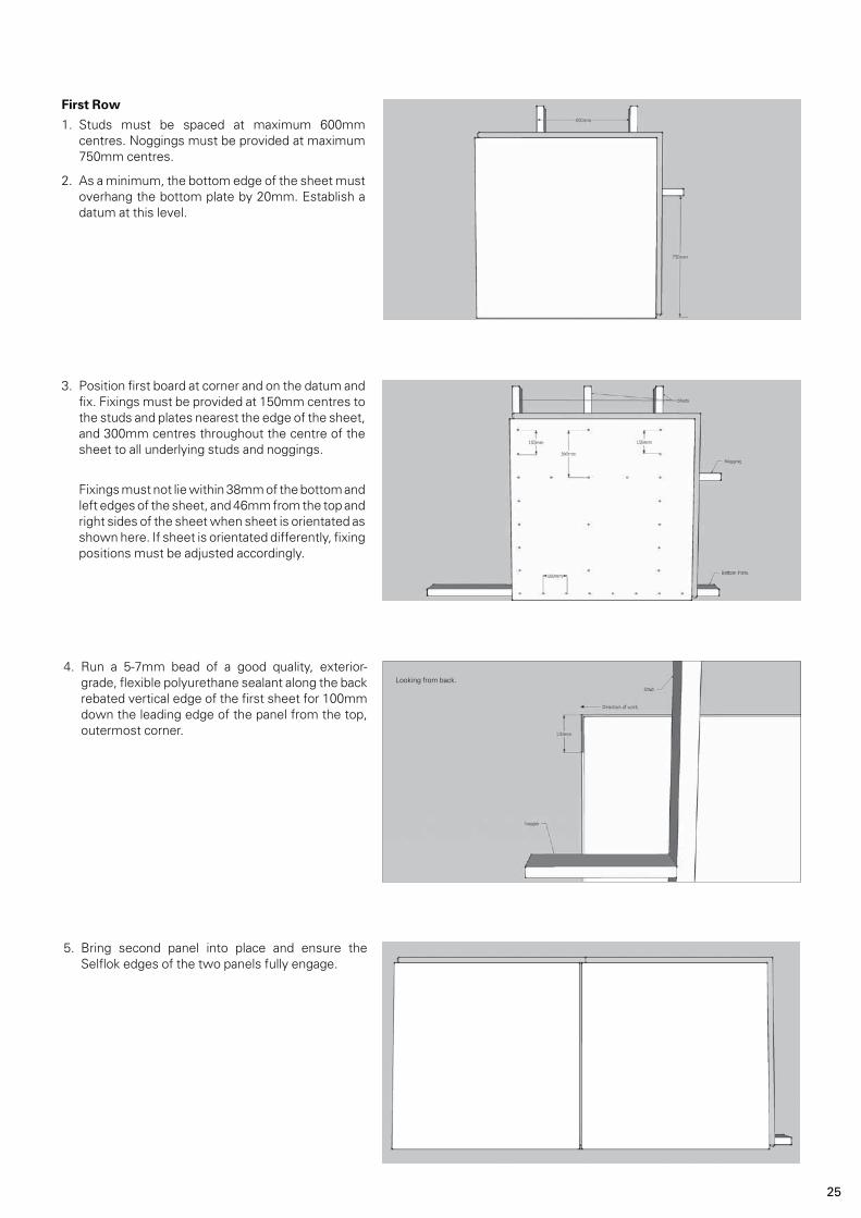
4. Run a 5-7mm bead of a good quality, exterior-grade, flexible polyurethane sealant along the back rebated vertical edge of the first sheet for 100mm down the leading edge of the panel from the top, outermost corner.
First Row
1. Studs must be spaced at maximum 600mm centres. Noggings must be provided at maximum 750mm centres.
2. As a minimum, the bottom edge of the sheet must overhang the bottom plate by 20mm. Establish a datum at this level.
3. Position first board at corner and on the datum and fix. Fixings must be provided at 150mm centres to the studs and plates nearest the edge of the sheet, and 300mm centres throughout the centre of the sheet to all underlying studs and noggings.
Fixings must not lie within 38mm of the bottom and left edges of the sheet, and 46mm from the top and right sides of the sheet when sheet is orientated as shown here. If sheet is orientated differently, fixing positions must be adjusted accordingly.
5. Bring second panel into place and ensure the Selflok edges of the two panels fully engage.
Looking from back.

26
Second Row
8. Starting from the same side of the wall as the bottom row, run a 5-7mm bead of a good quality, exterior-grade, flexible polyurethane sealant along the back rebated edge of the first sheet for 100mm either side of the join where two sheets below meet. This row of sealant is crucial to the installation and must be maintained throughout the life of the product to prevent water ingress.
View from the side of the wall showing run of sealant along back of Selflok section.
Looking down from the top you should see the Selflok fully engaged as is shown in the diagram below.
6. Secure second sheet as for first sheet.
7. Repeat to secure all first row sheets along wall. Trim the last sheet to length as required.
27
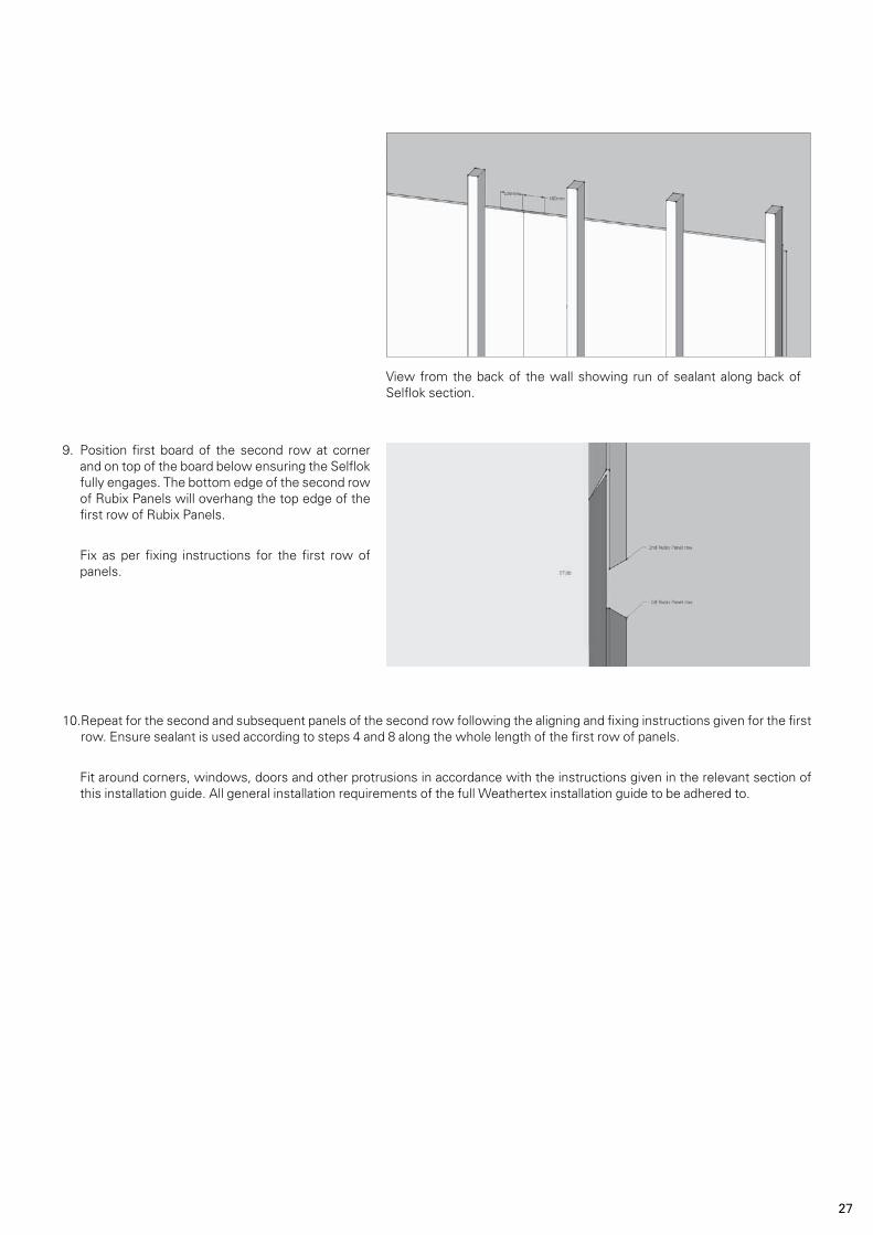
View from the back of the wall showing run of sealant along back of Selflok section.
9. Position first board of the second row at corner and on top of the board below ensuring the Selflok fully engages. The bottom edge of the second row of Rubix Panels will overhang the top edge of the first row of Rubix Panels.
Fix as per fixing instructions for the first row of panels.
10. Repeat for the second and subsequent panels of the second row following the aligning and fixing instructions given for the first row. Ensure sealant is used according to steps 4 and 8 along the whole length of the first row of panels.
Fit around corners, windows, doors and other protrusions in accordance with the instructions given in the relevant section of this installation guide. All general installation requirements of the full Weathertex installation guide to be adhered to.

28
INTERNAL INSTALLATION - CONCEALED FIXING
(FOR INTERNAL USE OF RUBIX PANEL ONLY)
These fixings are concealed by the corresponding Selflok section of the adjoining panels.
When installing Weathertex Rubix Panel internally, there is the option to conceal the fixings. When installing Rubix Panels using the concealed fixing method, the fixings in each panel are installed through the Selflok section of the panel.
As such, when using the concealed fixing method internally, horizontal and vertical joins must fall on studs and noggings, respectively.
The following fixing pattern shows the location of the fixings when using the concealed fixing method. All other factors of installing Rubix Panel using the concealed fixing method are as per the traditional fix instructions above.
When subsequent sheets are installed, the fixings are concealed.

29
MANUFACTURER’S WARRANTY1. Weathertex Pty Ltd A.B.N 67 084 713 986 (“Weathertex”) warrants that the Products supplied are of first quality, free from defect in material, design and workmanship, and in conformity with the technical specifications detailed in the published Weathertex Installation Guide that is current at the date of purchase.2. Natural Woodsman Board Weathertex warrants that its Natural
(Brown) Board Products will not rot, split or crack for a period of 7 (seven) years from the date of purchase when installed and maintained in accordance with Weathertex current published materials.
Pre Primed ExteriorBoard, High Impact Board & Rubix Panel Weathertex warrants that its ExteriorBoard Products will not rot, split or crack for a period of 10 (ten) years from the date of purchase when installed and maintained in accordance with Weathertex current published materials.
Pre Primed Board Weathertex warrants that its pre primed board Products will not rot, split or crack for a period of 25 (twenty-five) years from the date of purchase when prepared, installed and maintained in accordance with Weathertex current published materials. 3. A reference to Products in these warranty terms and conditions does not include accessory products listed “Accessories” in the Weathertex Price List (“Accessory Products”). Weathertex warrants that the Accessory Products will be free from defect in material and workmanship for a period of 7 years from the date of purchase for the purpose of clarity, the warranties provided in clause 1 and 2 do not apply to Accessory Products.
CONDITIONS OF THE WARRANTY4. The warranties provided in clauses 1, 2 and 3 are only available to the original purchaser (“Purchaser”) who provides Weathertex with proof of purchase and who makes the claim in writing within 30 days from the point in time when the defect becomes apparent or should have become apparent.5. Weathertex will not be liable for any warranty claims made under clauses 1 and 2 if any of the following apply: (a) the Products are not installed used or maintained in accordance with applicable instructions and/or specifications, including installation and site conditions provided by Weathertex (including the published Weathertex Installation Guide that is current at the date of purchase); (b) the building in which the Products are installed does not comply with all relevant Building Codes and Regulations, Standards, and Council/Authority/Regulator requirements; (c) the Purchaser has not complied with any service instructions which Weathertex may give or any subsequent request as to a modification of the Products which Weathertex may make from time to time in writing; (d) the defect is caused by the use of materials, parts or accessory products that are not supplied, recommended, or approved by Weathertex; (e) the Products are not maintained, prepared or installed by authorised installation contractors in circumstances where Weathertex has directed the Purchaser to ensure that the Products are maintained, prepared or installed by such authorised installation contractors; or (f) the repair, rectification or replacement of the Products is required as a result of normal wear and tear or necessitated in whole or in part by the fault or negligence of any person other than Weathertex.6. Further to clause 5 and without limiting clause 5, Weathertex, under no circumstances will be liable for any claims, damages, or defects arising from or in any way attributable to: (a) acts of God, fire, flood or other severe weather conditions or unusual climatic conditions; (b) performance of paint/coatings applied to the Products; (c) development of any algae, bacteria or fungi on the Products (whether on the exposed or unexposed surfaces); (d) poor workmanship; or (e) any other losses or damages (whether direct or indirect) including property damage or personal injury, consequential loss, economic loss or loss of profits arising in contract or negligence.
REMEDIES7. Should the Purchaser’s warranty claim made under clauses 1 and/or 2 be valid, then the remedy provided by Weathertex will be limited to either of the following as chosen by Weathertex: (a) Weathertex replacing the Products provided the claim is accepted by Weathertex and subject to such replacement Products being available in the manufacturing inventory at the time the claim is accepted by Weathertex. Otherwise, Weathertex will provide such replacement Products when they become available. The cost of replacing the Products being, at all material times, limited to the applicable sliding scale. (b) Weathertex repairing the Products provided the claim is accepted by Weathertex and subject to the cost of repairing the Products being, at all material times, limited to the applicable sliding scale.
8. Should the Purchaser’s warranty claim made under clause 3 be valid, then the remedy provided by Weathertex will be limited to Weathertex replacing the Accessory Products provided the claim is accepted by Weathertex and subject to such replacement Accessory Products being available in the manufacturing inventory at the time the claim is accepted by Weathertex. Otherwise, Weathertex will provide such replacement Accessory Products when they become available.9. The Purchaser is not entitled to any other remedies with respect to a warranty claim.10. Any replacement works will be conducted in accordance with the Building Codes and Regulations, Standards, and Council/Authority Regulator requirements applicable at the time of construction. Where the Building Codes and Regulations, Standards, and Council/ Authority Regulator requirements have changed after the Products were purchased, Weathertex will not be responsible for any costs associated with ensuring that the replacement works comply with the updated Building Codes and Regulations, Standards, and Council/ Authority Regulator requirements.11. Where an approved claim requires re-coating of the Products the Purchaser acknowledges and agrees to accept minor colour variations between the existing or original colour and the re-coated replacement Products.12. Except as provided for in these terms and to the fullest extent permitted by law, all terms, statements, warranties and conditions whether express, implied, statutory or otherwise, relating to the subject matter of these terms or to these terms generally are excluded. Nothing contained herein excludes or modifies any rights the Purchaser may have under the Australian Trade Practices Act 1974 (Cth) (or equivalent in other countries as determined by Weathertex in its sole discretion).
DISCLAIMER13. Recommendations made by Weathertex are based on good building practice and are not a complete statement of all relevant data. As the installation of the Products is influenced by and relies on factors outside the control of Weathertex, Weathertex assumes no responsibility for works/systems used in connection with the installation of the Products and their suitability to satisfy relevant Building Codes and Regulations, Standards, and Council/Authority /Regulator requirements.14. Unless specifically stated otherwise, this warranty applies to Weathertex products purchased and installed according to the Weathertex Installation Guide in Australia, Asia, Pacific Region and New Zealand.
Table 1: Sliding Scale of Warranty Repair CostsNatural Woodsman Board
Years of Service (commencing on
the date of purchase)
0 to 4 Years 4 to 7 Years
Limit of Warranty Repair Costs covered
subject to Claim being accepted 100% of replacement/repairing costs covered by Weathertex 50% of replacement/repairing costs covered by Weathertex
Table 3: Sliding Scale of Warranty Repair CostsPre Primed Board
Years of Service (commencing on
the date of purchase)
0 to 7 Years 8 to 15 Years
16 to 25 Years
Limit of Warranty Repair Costs covered
subject to Claim being accepted
100% of replacement/repairing costs covered by Weathertex 50% of replacement/repairing costs covered by Weathertex
25% of replacement/repairing costs covered by Weathertex
Table 2: Sliding Scale of Warranty Repair CostsPre Primed ExteriorBoard, High Impact Board & Rubix Panel
Years of Service (commencing on
the date of purchase)
0 to 6 Years 7 to 10 Years
Limit of Warranty Repair Costs covered
subject to Claim being accepted 100% of replacement/repairing costs covered by Weathertex 50% of replacement/repairing costs covered by Weathertex
Weathertex is made in Australia by Weathertex Pty Ltd ABN 67 084 713 986, Masonite Road, Raymond Terrace, NSW 2324
The information in this manual related to Weathertex’s product as developed and manufactured at the time of printing. Importantly, Weathertex follows a policy of continuous product testing and improvement. For this and other reasons Weathertex reserves the right to make any changes or modifications to this manual and any other relevant document as and when it considers necessary and without notice. Accordingly, users of Weathertex’s products are
encouraged to regularly contact Weathertex to obtain the current manual. This Installation Guide was printed September 2011.
w w w. w e a t h e r t e x . c o m . a u
P h : 1 8 0 0 0 4 0 0 8 0 F a x : 1 8 0 0 6 4 7 9 2 6
I n t . P h : + 6 1 2 4 9 8 0 3 1 0 0
* Refer to the Weathertex Manufacturer’s Warranty Conditions
PEFC/21-31-09


