ATTENTION INSTALLING PERSONNELAs a professional installer, you have an obligation to know theproduct better than the customer. This includes all safety pre-cautions and related items.
Prior to actual installation, thoroughly familiarize yourself withthis Instruction Manual. Pay special attention to all safety warn-ings. Often during installation or repair, it is possible to placeyourself in a position which is more hazardous than when theunit is in operation.
Remember, it is your responsibility to install the product safelyand to know it well enough to be able to instruct a customer inits safe use.
Safety is a matter of common sense...a matter of thinking beforeacting. Most dealers have a list of specific, good safetypractices...follow them.
The precautions listed in this Installation Manual are intendedas supplemental to existing practices. However, if there is adirect conflict between existing practices and the content ofthis manual, the precautions listed here take precedence.
RECOGNIZE THIS SYMBOL
AS A SAFETY PRECAUTION
NOTE: Please contact your distributor or our website listedbelow for the applicable Specification Sheet referred to in thismanual.
Installer: Affix all manualsadjacent to the unit.
These furnaces comply with requirements embodied inthe American National Standard / National Standard ofCanada ANSI Z21.47·CSA-2.3 Gas Fired Central Furnaces.
IOG-2021A05/2019
INSTALLATION INSTRUCTIONS FOR*MES80 / *CES80 GAS FURNACE (CATEGORY I ) (CATÉGORY I )
is a registered trademark of Maytag Corporation or its related companies and is used under license. All rights reserved.
COMBUSTION AND VENTILATION AIR REQUIREMENTS ........... 10CATEGORY I VENTING (VERTICAL VENTING) ............................ 10EXTERIOR MASONRY CHIMNEYS
(CATEGORY I FURNACES ONLY) ......................................... 12Checklist Summary .......................................................... 12Check 1 - Proper chimney termination .......................... 12Check 2 - Any solid or liquid fuel appliances
Cancer and Reproductive Harm -www.P65Warnings.ca.gov
PROP 65 WARNINGFOR CALIFORNIA CONSUMERS
0140M00517-A
ONLY PERSONNEL THAT HAVE BEEN TRAINED TO INSTALL, ADJUST, SERVICE OR REPAIR (HEREINAFTER, “SERVICE”) THE EQUIPMENT SPECIFIED IN THIS MANUAL SHOULD SERVICE THE EQUIPMENT. THE MANUFACTURER WILL NOT BE RESPONSIBLE FOR ANY INJURY OR PROPERTY DAMAGE ARISING FROM IMPROPER SERVICE OR SERVICE PROCEDURES. IF YOU SERVICE THIS UNIT, YOU ASSUME RESPONSIBILITY FOR ANY INJURY OR PROPERTY DAMAGE WHICH MAY RESULT. IN ADDITION, IN JURISDICTIONS THAT REQUIRE ONE OR MORE LICENSES TO SERVICE THE EQUIPMENT SPECIFIED IN THIS MANUAL, ONLY LICENSED PERSONNEL SHOULD SERVICE THE EQUIPMENT. IMPROPER INSTALLATION , ADJUSTMENT, SERVICING OR REPAIR OF THE EQUIPMENT SPECIFIED IN THIS MANUAL, OR ATTEMPTING TO INSTALL, ADJUST, SERVICE OR REPAIR THE EQUIPMENT SPECIFIED IN THIS MANUAL WITHOUT PROPER TRAINING MAY RESULT IN PRODUCT DAMAGE, PROPERTY DAMAGE, PERSONAL INJURY OR DEATH.
2
ELECTRICAL CONNECTIONS ................................................... 15Wiring Harness ............................................................... 15115 Volt Line Connections ............................................. 16Fossil Fuel Applications .................................................. 16Junction Box Relocation ................................................. 1624 Volt Thermostat Wiring ............................................ 16GME8 & AMEH8 Furnaces
with 2-Stage Condenser Field Wiring ........................ 17Setting the Heat Anticipator .......................................... 17115 Volt Line Connection of Accessories ....................... 17Electronic Air Cleaner ..................................................... 1724 Vac Humidifier ........................................................... 17
GAS SUPPLY AND PIPING ...................................................... 18High Altitude Derate ....................................................... 18Propane Gas Conversion ................................................ 18Gas Piping Connections .................................................. 19Upflow Installations ........................................................ 20Counterflow Installations ............................................... 20Gas Piping Checks ........................................................... 20Propane Gas Tanks and Piping ....................................... 21
CIRCULATING AIR AND FILTERS ............................................. 22Ductwork - Air Flow ........................................................ 22Filters - Read This Section BeforeInstalling The Return Air Ductwork ................................ 22Upright Installations ....................................................... 22Circulation Air Filters ...................................................... 22Horizontal Installations .................................................. 23
SEQUENCE OF OPERATION(INTEGRATED IGNITION CONTROL) ................................... 23
Power Up ......................................................................... 23Heating Mode ................................................................. 24Cooling Mode.................................................................. 24Fan Only Mode ............................................................... 24
GOODMAN DAMAGE ARISING FROM IMPROPER SERVICE OR SERVICE PROCEDURES. IF YOU INSTALL OR PERFORM SERVICE ON THIS UNIT, YOU ASSUME RESPONSIBILITY FOR ANY PERSONAL INJURY OR PROPERTY DAMAGE WHICH MAY RESULT. MANY JURISDICTIONS REQUIRE A LICENSE TO INSTALL OR SERVICE HEATING AND AIR CONDITIONING EQUIPMENT.
WILL NOT BE RESPONSIBLE FOR ANY INJURY OR PROPERTY
WARNING
SAFETY CONSIDERATIONS
Adhere to the following warnings and cautions when installing,adjusting, altering, servicing, or operating the furnace. To ensureproper installation and operation, thoroughly read this manualfor specifics pertaining to the installation and application of thisproduct.
This furnace is manufactured for use with natural gas. It may befield converted to operate on L.P. gas by using the appropriate L.P.conversion kit listed in the PROPANE GAS/HIGH ALTITUDE INSTAL-LATIONS section of this manual
Install this furnace only in a location and position as specified inLOCATION REQUIREMENTS & CONSIDERATIONS section and INSTAL-LATION POSITIONS section of this manual.
Provide adequate combustion and ventilation air to the furnaceas specified in COMBUSTION & VENTILATION AIR REQUIREMENTSsection of this manual.
Combustion products must be discharged to the outdoors. Con-nect this furnace to an approved vent system only, as specified inCATEGORY 1 VENTING section of this manual.
Never test for gas leaks with an open flame. Use a commerciallyavailable soap solution made specifically for the detection ofleaks to check all connections, as specified in GAS SUPPLY ANDPIPING section of this manual.
Always install a furnace to operate within the furnace’s intendedtemperature-rise range with a duct system which has externalstatic pressure within the allowable range, as specified on thefurnace rating plate and OPERATIONAL CHECKS section of theseinstructions.
When a furnace is installed so that supply ducts carry air circu-lated by the furnace to areas outside the space containing thefurnace, the return air shall also be handled by duct(s) sealed tothe furnace casing and terminating outside the space containingthe furnace.
A gas-fired furnace for installation in a residential garage mustbe installed as specified in the LOCATION REQUIREMENTS ANDCONSIDERATIONS section of this manual.
This furnace may be used as a construction site heater only ifcertain conditions are met. These conditions are listed in the PROD-UCT APPLICATION section of this manual.
TO PREVENT PERSONAL INJURY OR DEATH DUE TO IMPROPER INSTALLATION, ADJUSTMENT, ALTERATION, SERVICE OR MAINTENANCE, REFER TO THIS MANUAL. FOR ADDITIONAL ASSISTANCE OR INFORMATION, CONSULT A QUALIFIED INSTALLER, SERVICER AGENCY OR THE GAS SUPPLIER.
WARNING
FIRE OR EXPLOSION HAZARDFAILURE TO FOLLOW THE SAFETY WARNINGS EXACTLY COULD RESULT IN SERIOUS INJURY, DEATH OR PROPERTY DAMAGE. NEVER TEST FOR GAS LEAKS WITH AN OPEN FLAME. USE COMMERCIALLY AVAILABLE SOAP SOLUTION MADE SPECIFICALLY FOR THE DETECTION OF LEAKS TO CHECK ALL CONNECTIONS. A FIRE OR EXPLOSION MAY RESULT CAUSING PROPERTY DAMAGE, PERSONAL INJURY OR LOSS OF LIFE.
RISQUE D’INCENDIE OU D’EXPLOSION
SI LES CONSIGNES DE SÉCURITÉ NE SONT PAS SUIVIES À LA LETTRE, CELA PEUT ENTRAÎNER LA MORT, DE GRAVES BLESSURES OU DES DOMMAGES MATÉRIELS. NE JAMAIS VÉRIFIER LA PRÉ SENCE DE FUITES DE GAZ AU MOYEN D'UNE FLAMME NUE. VÉRIFIER TOUS LES RACCORDS EN UTILISANT UNE SOLUTION SAVONNEUSE COMMERCIALE CONÇ UE SPÉ CIALEMENT POUR LA DÉTECTION DE FUITES. UN INCENDIE OU UNE EXPLOSION RISQUE DE SE PRODUIRE, CE QUI PEUT ENTRAÎNER LA MORT, DES BLESSURES OU DES DOMMAGES MATÉRIELS.
IF THE INFORMATION IN THESE INSTRUCTIONS IS NOT FOLLOWED EXACTLY, A FIRE OR EXPLOSION MAY RESULT CAUSING PROPERTYDAMAGE, PERSONAL INJURY OR LOSS OF LIFE.
DO NOT STORE OR USE GASOLINE OR OTHER FLAMMABLE VAPORS AND LIQUIDS IN THE VICINITY OF THIS OR ANY OTHER APPLIANCE.
DO NOT TRY TO LIGHT ANY APPLIANCE.DO NOT TOUCH ANY ELECTRICAL SWITCH; DO NOT USE ANY PHONE IN YOUR BUILDING.IMMEDIATELY CALL YOUR GAS SUPPLIER FROM A NEIGHBOR’S PHONE. FOLLOW THE GAS SUPPLIER’S INSTRUCTIONS.IF YOU CANNOT REACH YOUR GAS SUPPLIER, CALL THE FIRE DEPARTMENT.
INSTALLATION AND SERVICE MUST BE PERFORMED BY A QUALIFIED INSTALLER, SERVICE AGENCY OR THE GAS SUPPLIER.
WHAT TO DO IF YOU SMELL GAS:
WARNING
THIS PRODUCT CONTAINS OR PRODUCES A CHEMICAL OR CHEMICALS WHICH MAY CAUSE SERIOUS ILLNESS OR DEATH AND WHICH ARE KNOWN TO THE STATE OF CALIFORNIA TO CAUSE CANCER, BIRTH DEFECTS OR OTHER REPRODUCTIVE HARM.
WARNING
4
HEATING UNIT SHOULD NOT BE UTILIZED WITHOUT REASONABLE, ROUTINE, INSPECTION, MAINTENANCE AND SUPERVISION. IF THE BUILDING IN WHICH ANY SUCH DEVICE IS LOCATED WILL BE VACANT, CARE SHOULD BE TAKEN THAT SUCH DEVICE IS ROUTINELY INSPECTED, MAINTAINED AND MONITORED. IN THE EVENT THAT THE BUILDING MAYBE EXPOSED TO FREEZING TEMPERATURES AND WILL BE VACANT, ALL WATER-BEARING PIPES SHOULD BE DRAINED, THE BUILDING SHOULD BE PROPERLY WINTERIZED, AND THE WATER SOURCE CLOSED. IN THE EVENT THAT THE BUILDING MAY BE EXPOSED TO FREEZING TEMPERATURES AND WILL BE VACANT, ANY HYDRONIC COIL UNITS SHOULD BE DRAINED AS WELL AND, IN SUCH CASE, ALTERNATIVE HEAT SOURCES SHOULD BE UTILIZED.
WARNING
TO PREVENT POSSIBLE PROPERTY DAMAGE, PERSONAL INJURY OR DEATH DUE TO ELECTRICAL SHOCK, THE FURNACE MUST BE LOCATED TO PROTECT THE ELECTRICAL COMPONENTS FROM WATER.
WARNING
CARBON MONOXIDE POISONING HAZARDFailure To Follow The Steps Outlined Below For Each Appliance Connected To The Venting System Being Placed Into Operation Could Result In Carbon Monoxide Poisoning Or Death. The Following Steps Shall Be Followed For Each Appliance Connected To The Venting System Being Placed Into Operation, While All Other Appliances Connected To The Venting System Are Not In Operation: 1) Seal Any Unused Openings In The Venting System. 2) Inspect The Venting System For Proper Size And Horizontal Pitch, As Required In The National Fuel Gas Code, Ansi Z223.1/nfpa 54 Or The Natural Gas And Propane Installation Code, Csa B149.1 And These Instructions. Determine That There Is No Blockage Or Restriction, Leakage, Corrosion And Other Deficiencies Which Could Cause An Unsafe Condition. 3) As Far As Practical, Close All Building Doors And Windows And All Doors Between The Space In Which The Appliance(s) Connected To The Venting System Are Located And Other Spaces Of The Building.4) Close Fireplace Dampers. 5) Turn On Clothes Dryers And Any Appliance Not Connected To The Venting System. Turn On Any Exhaust Fans, Such As Range Hoods And Bathroom Exhausts, So They Are Operating At Maximum Speed. Do Not Operate A Summer Exhaust Fan. 6) Follow The Lighting Instructions. Place The Appliance Being Inspected Into Operation. Adjust The Thermostat So Appliance Is Operating Continuously.7) Test For Spillage From Draft Hood Equipped Appliances At The Draft Hood Relief Opening After 5 Minutes Of Main Burner Operation. Use The Flame Of A Match Or Candle.8) If Improper Venting Is Observed During Any Of The Above Tests, The Venting System Must Be Corrected In Accordance With The National Fuel Gas Code, Ansi Z223.1/nfpa 54 And/or Natural Gas And Propane Installation Code, Csa B149.1. 9) After It Has Been Determined That Each Appliance Connected To The Venting System Properly Vents When Tested As Outlined Above, Return Doors, Windows, Exhaust Fans, Fireplace Dampers And Any Other Gas-fired Burning Appliance To Their Previous Conditions Of Use.
RISQUE D’INTOXICATION AU MONOXYDE DE CARBONESi les étapes décrites ci-dessous ne sont pas suivies pour chacun des appareils raccordés au système de ventilation au moment de sa mise en marche, cela peut entraîner une intoxication au monoxyde de carbone ou la mort. Les étapes suivantes doivent être suivies pour chacun des appareils raccordés au système de ventilation au moment de sa mise en marche, alors que tous les autres appareils raccordés au système de ventilation ne sont pas en marche:1) Sceller toutes les ouvertures inutilisées du système de ventilation. 2) Inspecter le système de ventilation afin de vérifier si la taille et l’inclinaison par rapport à l’horizontale sont conformes aux exigences du National Fuel Gas Code, ANSI Z223.1/NFPA 54 ou du Code d’installation du gaz naturel et du propane, CSA B149.1 et à ces instructions. Vérifier qu’il n’y pas d’obstruction ou de pourraient entraîner une situation dangereuse. 3) Si possible, fermer toutes les portes et fenêtres du bâtiment ainsi que toutes les portes séparant l’endroit où se trouvent les appareils raccordés au système de ventilation et less autres zones du bâtiment. 4) Fermer le registre des foyers.5) Mettre les sécheuses en marche ainsi que tous les autres appareils qui ne sont pas raccordés au systéme de ventilation. Mettre en marche tous les ventilateurs de tirage, comme celui des hottes de cuisine et des salles de bains, et les régler à la puissance maximale. Ne pas mettre en marche les ventilateurs d’été.6) Suivre les instructions d’allumage. Mettre en marche l’appareil soumis à l’inspection. Régler le thermostat de manièr à ce que l’appareil fonctionne en continu. 7) Vérifier la présence de fuite au niveau de l’ouverture du coupe-tirage des appareils qui en sont dotés après 5 minutes de fontionnement du brûleur principal. Utiliser la flamme d’une allumette ou d’une bougie. 8) Si un problème de ventilation est observé pendant l’un des essaid décrits ci-dessus, des correctifs doivent être apportés au système de ventilation conformé National Fuel Gas Code, Ansi Z223.1/nfpa 54 And/or Natural Gas And Propane Installation Code, Csa B149.1. 9) Une fois qu’il été déterminé que chaque appareil raccordé au système de ventilation fontionne correctement au moyen des essais décrits ci-dessus, les portes, les fenêtres, les ventilateurs, les registres de foyer et tous les autres appareils de combustion alimentés au gaz doivent être remis dans leur état initial.
5
B10259-216CO can cause serious illness including permanent braindamage or death.
Advertencia especial para la instalación de calentadores ó manejadoras de aire en áreas cerradas como estacionamientos ó cuartos de servicio.
B10259-216
El monóxido de carbono puede causar enfermedades severas como daño cerebral permanente ó muerte.
Las emisiones de monóxido de carbono pueden circular a travésdel aparato cuando se opera en cualquier modo.
B10259-216
RISQUE D'EMPOISONNEMENT AU MONOXYDE DE CARBONE
Le monoxyde de des
carbone peut causer des maladies graves telles quedommages permanents au cerveau et meme la mort.
Cette ventilation est nécessaire pour éviter le danger d'intoxicationau CO pouvant survenir si un appareil produisant du monoxyde de carbone continue de fonctionner au sein de la zone confinée.
SHOULD OVERHEATING OCCUR OR THE GAS SUPPLY FAIL TO SHUT OFF, TURN OFF THE MANUAL GAS SHUTOFF VALVE EXTERNAL TO THE FURNACE BEFORE TURNING OFF THE ELECTRICAL SUPPLY.
WARNING
POSSIBLE PROPERTY DAMAGE, PERSONAL INJURY OR DEATH DUE TO FIRE, EXPLOSION, SMOKE, SOOT, CONDENSATION, ELECTRICAL SHOCK OR CARBON MONOXIDE MAY RESULT FROM IMPROPER INSTALLATION, REPAIR OPERATION, OR MAINTENANCE OF THIS PRODUCT.
WARNING
TO PREVENT PERSONAL INJURY OR DEATH DUE TO IMPROPER INSTALLATION, ADJUSTMENT, ALTERATION, SERVICE OR MAINTENANCE, REFER TO THIS MANUAL. FOR ADDITIONAL ASSISTANCE OR INFORMATION, CONSULT A QUALIFIED INSTALLER, SERVICER AGENCY OR THE GAS SUPPLIER.
WARNING
TO PREVENT PERSONAL INJURY OR DEATH DUE TO ASPHYXIATION, THIS FURNACE MUST BE CATEGORY I VENTED. DO NOT VENT USING CATEGORY III VENTING.PROVISIONS MUST BE MADE FOR VENTING COMBUSTION PRODUCTS OUTDOORS THROUGH A PROPER VENTING SYSTEM. THE LENGTH OF FLUE PIPE COULD BE A LIMITING FACTOR IN LOCATING THE FURNACE.
WARNING
ADDITIONAL SAFETY CONSIDERATIONS• This furnace is approved for Category I Venting only.• Provisions must be made for venting combustion
products outdoors through a proper venting system. Thelength of flue pipe could be a limiting factor in locatingthe furnace.
SHIPPING INSPECTION
All units are securely packed in shipping containers tested ac-cording to International Safe Transit Association specifications.The carton must be checked upon arrival for external damage. Ifdamage is found, a request for inspection by carrier’s agent mustbe made in writing immediately.
The furnace must be carefully inspected on arrival for damageand bolts or screws which may have come loose in transit. In theevent of damage the consignee should:1. Make a notation on delivery receipt of any visible damage
to shipment or container.2. Notify carrier promptly and request an inspection.3. With concealed damage, carrier must be notified as soon
as possible - preferably within five days.4. File the claim with the following support documents within
a nine month statute of limitations.• Original or certified copy of the Bill of Lading, or
indemnity bond.• Original paid freight bill or indemnity in lieu thereof.• Original or certified copy of the invoice, showing trade
and other discounts or reductions.• Copy of the inspection report issued by carrier ’s
representative at the time damage is reported to carrier.
The carrier is responsible for making prompt inspection of dam-age and for a thorough investigation of each claim. The distribu-tor or manufacturer will not accept claims from dealers for trans-portation damage.
Keep this literature in a safe place for future reference.
6
ELECTROSTATIC DISCHARGE (ESD) PRECAUTIONS
NOTE: Discharge body’s static electricity before touching unit.An electrostatic discharge can adversely affect electrical compo-nents.
Use the following precautions during furnace installation and ser-vicing to protect the integrated control module from damage. Byputting the furnace, the control, and the person at the same elec-trostatic potential, these steps will help avoid exposing the inte-grated control module to electrostatic discharge. This procedureis applicable to both installed and non-installed (ungrounded)furnaces.1. Disconnect all power to the furnace. Do not touch the
integrated control module or any wire connected to thecontrol prior to discharging your body’s electrostaticcharge to ground.
2. Firmly touch a clean, unpainted, metal surface of thefurnaces near the control. Any tools held in a person’shand during grounding will be discharged.
3. Service integrated control module or connecting wiringfollowing the discharge process in step 2. Use caution notto recharge your body with static electricity; (i.e., do notmove or shuffle your feet, do not touch ungrounded objects,etc.). If you come in contact with an ungrounded object,repeat step 2 before touching control or wires.
4. Discharge your body to ground before removing a newcontrol from its container. Follow steps 1 through 3 ifinstalling the control on a furnace. Return any old or newcontrols to their containers before touching anyungrounded object.
TO THE INSTALLER
Before installing this unit, please read this manual thoroughly tofamiliarize yourself with specific items which must be adhered to,including but not limited to: unit maximum external static pres-sure, gas pressures, BTU input rating, proper electrical connec-tions, circulating air temperature rise, minimum or maximum CFM,and motor speed connections, and venting. These furnaces aredesigned for Category I venting only.
TO PREVENT PROPERTY DAMAGE, PERSONAL INJURY OR DEATH DUE TO FIRE, DO NOT INSTALL THIS FURNACE IN A MOBILE HOME, TRAILER, OR RECREATIONAL VEHICLE.
WARNING
PRODUCT APPLICATION
This furnace is primarily designed for residential home-heatingapplications. It is NOT designed or certified for use in mobilehomes, trailers or recreational vehicles. Neither is it designed orcertified for outdoor applications. The furnace must be installedindoors (i.e., attic space, crawl space, or garage area provided thegarage area is enclosed with an operating door).
This furnace can be used in the following non-industrial commer-cial applications:
Nursing homes, Hotels/motels, Common or office areas
In such applications , the furnace must be installed with the fol-lowing stipulations:
• It must be installed per the installation instructionsprovided and per local and national codes.
• It must be installed indoors in a building constructed onsite.
• It must be part of a ducted system and not used in a freeair delivery application.
• It must not be used as a “make-up” air unit.• All other warranty exclusions and restrictions apply.
This furnace may be used as a construction site heater ONLY if thefollowing conditions are met:
• The vent system is permanently installed per theseinstallation instructions.
• A room thermostat is used to control the furnace. Fixedjumpers that provide continuous heating CANNOT be usedand can cause long term equipment damage. Bi-metalthermostats, or any thermostat affected by vibration mustnot be used during construction.
• Return air ducts are provided and sealed to the furnace.• A return air temperature range between 60ºF (16ºC) and
80ºF (27ºC) is maintained.• Air filters are installed in the system and replaced daily
during construction and upon completion ofconstruction.
• The input rate and temperature rise are set per thefurnace rating plate.
• 100% outside air must be used for combustion duringconstruction. Temporary ducting may be used to supplyoutside air to the furnace for combustion – do not connectthis duct directly to the furnace. Size this duct accordingto NFPA 54/ANSI Z223.1 section for Combustion andVentilation Air.
• The furnace heat exchanger, components, duct system,air filters and evaporator coils are thoroughly cleanedfollowing final construction clean up by a qualifiedperson.
• All furnace operating conditions (including ignition,input rate, temperature rise and venting) are verified bya qualified person according to these installationinstructions.
• Furnace doors must be in place on the furnace while thefurnace is operating in any mode.
Damage or repairs due to failure to comply with these require-ments are not covered under the warranty.
NOTE: The Commonwealth of Massachusetts requires that thefollowing additional requirements must also be met:
• Gas furnaces must be installed by a licensed plumber orgas fitter.
• A T-handle gas cock must be used.• If the unit is to be installed in an attic, the passageway to
and the service area around the unit must have flooring.
7
Downflow models GD(H,S) ARE NOT APPROVED FOR HORIZON-TAL OR UPFLOW INSTALLATIONS. For these models, use only theinstructions for downflow installation only.
TO PREVENT POSSIBLE EQUIPMENT DAMAGE, PROPERTY DAMAGE, PERSONAL INJURY OR DEATH, THE FOLLOWING BULLET POINTS MUST BE OBSERVED WHEN INSTALLING THIS UNIT.
WARNING
Follow the instructions listed below when selecting a furnace lo-cation. Refer also to the guidelines provided in Combustion andVentilation Air Requirements.
• Centrally locate the furnace with respect to the proposedor existing air distribution system.
• Ensure the temperature of the return air entering thefurnace is between 55°F and 100°F when the furnace isheating.
• If the furnace is installed in an application where thetypical operating sound level of a furnace is deemedobjectionable, an optional sound reduction kit isavailable. Consult your local distributor for more details.
• Provisions must be made for venting combustionproducts outdoors through a proper venting system. Thelength of flue pipe could be a limiting factor in locatingthe furnace.
• Ensure adequate combustion air is available for thefurnace. Improper or insufficient combustion air canexpose building occupants to gas combustion productsthat could include carbon monoxide. Refer toCombustion and Ventilation Air Requirements.
• The furnace must be level. If the furnace is to be set ona floor that may become wet or damp at times, thefurnace should be supported above the floor on aconcrete base sized approximately 1-1/2" larger than thebase of the furnace.
• Ensure upflow or horizontal furnaces are not installeddirectly on carpeting, or any other combustible material.The only combustible material allowed is wood.
• Exposure to contaminated combustion air will result insafety and performance-related problems. Do not installthe furnace where the combustion air is exposed to thefollowing substances:
chlorinated waxes or cleanerschlorine-based swimming pool chemicals
water softening chemicalsdeicing salts or chemicals
carbon tetrachloridehalogen type refrigerants
cleaning solutions (such as perchloroethylene)printing inks
paint removersvarnishes
hydrochloric acidcements and glues
antistatic fabric softeners for clothes dryersand masonry acid washing materials
• If the furnace is used in connection with a cooling unit,install the furnace upstream or in parallel with the
TO PREVENT PROPERTY DAMAGE, PERSONAL INJURY OR DEATH DUE TO FIRE, DO NOT INSTALL THIS FURNACE IN A MOBILE HOME, TRAILER, OR RECREATIONAL VEHICLE.
WARNING
To ensure proper furnace operation, install, operate and main-tain the furnace in accordance with these installation and op-eration instructions, all local building codes and ordinances. Intheir absence, follow the latest edition of the National Fuel GasCode (NFPA 54/ANSI Z223.1), and/or CAN/CSA B149 InstallationCodes, local plumbing or waste water codes, and other applicablecodes.
A copy of the National Fuel Gas Code (NFPA 54/ANSI Z223.1) canbe obtained from any of the following:
American National Standards Institute25 West 43rd Street, 4th Floor
New York, NY 10036
National Fire Protection Association1 Batterymarch Park
Quincy, MA 02169-7471
CSA International8501 East Pleasant Valley
Cleveland, OH 44131
The rated heating capacity of the furnace should be greater thanor equal to the total heat loss of the area to be heated. The totalheat loss should be calculated by an approved method or in ac-cordance with “ASHRAE Guide” or “Manual J-Load Calculations”published by the Air Conditioning Contractors of America.
In the USA, this furnace MUST be installed in accordance with thelatest edition of the ANSI Z223.1 booklet entitled “National FuelGas Code” (NFPA 54), and the requirements or codes of the localutility or other authority having jurisdiction. Additional helpfulpublications available from the NFPA are, NFPA 90A - Installationof Air Conditioning and Ventilating System and NFPA 90B - WarmAir Heating and Air Conditioning System.
All venting shall be in accordance with the National Fuel GasCode, ANSI Z223.1, or applicable local building and/or air condi-tioning codes.
NOTE: Furnaces with NOx screens meet the California NOx emis-sion standards and California seasonal efficiency standards. AN-NUAL inspections of the furnace and its vent system is stronglyrecommended.
LOCATION REQUIREMENTS AND CONSIDERATIONS
Your unit model type determines which installation proceduresmust be used. For *MH8, *MS8, and GHS8 models, you must followinstructions for Horizontal Left, Horizontal Right or Upflow instal-lations only. These furnaces are not approved for Downflow in-stallations.
8
cooling unit coil. Premature heat exchanger failure willresult if the cooling unit coil is placed ahead of thefurnace.For vertical (upflow or downflow) applications, theminimum cooling coil width shall not be less than furnacewidth minus 1”. Additionally, a coil installed above anupflow furnace or under a counterflow furnace may bethe same width as the furnace or may be one size largerthan the furnace. Example: a “C” width coil may beinstalled with a “B” width furnace.
For upflow applications, the front of the coil and furnacemust face the same direction.
• If the furnace is installed in a residential garage, positionthe furnace so that the burners and ignition source arelocated not less than 18 inches (457 mm) above the floor.Protect the furnace from physical damage by vehicles.
• If the furnace is installed horizontally, the furnace accessdoors must be vertical so that the burners fire horizontallyinto the heat exchanger. Do not install the unit with theaccess doors on the “up/top” or “down/bottom” side ofthe furnace.
• Do not connect this furnace to a chimney flue that servesa separate appliance designed to burn solid fuel.
• For counterflow installations, the air conditioning coilmust be downstream from the heat exchanger of thefurnace.
• Counterflow installation over a noncombustible floor.Before setting the furnace over the plenum opening,ensure the surface around the opening is smooth andlevel. A tight seal should be made between the furnacebase and floor by using a silicon rubber caulkingcompound or cement grout.
• Counterflow installation over a combustible floor. Ifinstallation over a combustible floor becomes necessary,use an accessory subbase (see Specification Sheetapplicable to your model for details). A special accessorysubbase must be used for upright counterflow unitinstallations over any combustible material includingwood. Follow the instructions with the subbase for properinstallations. Do not install the furnace directly oncarpeting, tile, or other combustible material other thanwood flooring. (NOTE: The subbase will not be requiredif an air conditioning coil is installed between the supplyair opening on the furnace and the floor.
Top - 1"
SideClearance - 1"
Back - 0"
Front Clearance - 3"
Vent Pipe Clearance to Combustibles-6" using Single Wall Connector or 1"using B-1 vent.
• Adequate combustion/ventilation air must be suppliedto the closet.
• Furnace must be completely sealed to floor or base.Combustion/ ventilation air supply pipes must terminate12" from top of closet and 12" from floor of closet. DONOT remove solid base plate for side return.
• Return air ducts must be completely sealed to the furnaceand terminate outside the enclosure surfaces.
CLEARANCES AND ACCESSIBILITY
Clearance in accordance with local installation codes, therequirements of the gas supplies and the manufacturer ’sinstallation instructions.
Dégaugement conforme aux codes d’installation locaux, auxexigences du fournisseur de gaz et aux instrions d’installatino dufabricant.
Unobstructed front clearance of 24" for servicing is recommended.TOP
B1-VENT SINGLE (PLENUM)
1" 6" 1" 3" 0" 1"
VENT SIDES FRONT BACK
Top clearance for horizontal configuration - 1"
INSTALLATION POSITIONS
An upflow furnace may be installed in an upright position or hori-zontal on either the left or right side panel. Do not install thisfurnace on its back. For vertically installed upflow furnaces, re-turn air ductwork may be attached to the side panel(s) and/orbasepan. For horizontally installed upflow furnaces, return airductwork must be attached to the basepan. For counterflow fur-naces, return ductwork must be attached to the top end of theblower compartment.
NOTE: Ductwork must never be attached to the back of thefurnace.
9
Line contact to framing is permitted when installed in the horizon-tal configuration. Line contact is defined as the portion of thecabinet that is formed by the intersection of the top and side.ACCESSIBILITY CLEARANCE, WHERE GREATER, SHOULD TAKE PRE-CEDENCE OVER MINIMUM FIRE PROTECTION CLEARANCE. A gas-fired furnace for installation in a residential garage must be in-stalled so that the ignition source and burners are located notless than eighteen inches (18") above the floor and is protectedor located to prevent physical damage by vehicles. A gas furnacemust not be installed directly on carpeting, tile, or other com-bustible materials other than wood flooring.
FURNACE SUSPENSIONIf suspending the furnace from rafters or joist, use 3/8" threadedrod and 2”x2”x3/8” angle iron as shown below. The length of rodwill depend on the application and the clearances necessary.
Suspended Furnace
EXISTING FURNACE REMOVAL
NOTE: When an existing furnace is removed from a venting systemserving other appliances, the venting system may be too large toproperly vent the remaining attached appliances.The following vent testing procedure is reproduced from theAmerican National Standard/National Standard of Canada forGas-Fired Central Furnaces ANSI Z21.47-Latest Edition, CSA-2.3-Latest Edition Section 1.23.1. The following steps shall be fol-lowed with each appliance connected to the venting systemplaced in operation, while any other appliances connected to theventing system are not in operation:
a. Seal any unused openings in the venting system;b. Inspect the venting system for proper size and
horizontal pitch, as required by the National Fuel GasCode, ANSI Z223.1 or the CAN/CSA B149 InstallationCodes and these instructions. Determine that there isno blockage or restriction, leakage, corrosion and otherdeficiencies which could cause an unsafe condition;
c. In so far as practical, close all building doors andwindows and all doors between the space in which theappliance(s) connected to the venting system arelocated and other spaces of the building. Turn on clothesdryers and any appliance not connected to the ventingsystem. Turn on any exhaust fans, such as range hoodsand bathroom exhausts, so they shall operate atmaximum speed. Do not operate a summer exhaust fan.Close fireplace dampers;
HORIZONTAL INSTALLATION
Recomended Installarion Positions
Forhorizontal installations,
insert the#8 x 5/8 screw
from theliterature package.
10
d. Follow the lighting instructions. Place the appliance beinginspected in operation. Adjust thermostat so applianceshall operate continuously;
e. Test for draft hood equipped appliance spillage at thedraft hood relief opening after 5 minutes of main burneroperation. Use the flame of a match or candle;
f. After it has been determined that each applianceconnected to the venting system properly vents whentested as outlined above, return doors, windows,exhaust fans, fireplace dampers and any other gasburning appliance to their previous conditions of use;
g. If improper venting is observed during any of the abovetests, the common venting system must be corrected.
Corrections must be in accordance with the latest edition of theNational Fuel Gas Code NFPA 54/ANSI Z223.1 and/or CAN/CSAB149 Installation Codes.
If resizing is required on any portion of the venting system, usethe appropriate table in the latest edition of the National FuelGas Code ANSI Z223.1 and/or CAN/CSA B149 Installation Codes.
THERMOSTAT LOCATION
In an area having good air circulation, locate the thermostatabout five feet high on a vibration-free inside wall. Do not installthe thermostat where it may be influenced by any of the follow-ing:
• Drafts, or dead spots behind doors, in corners, or undercabinets.
• Hot or cold air from registers.• Radiant heat from the sun.• Light fixtures or other appliances.• Radiant heat from a fireplace.• Concealed hot or cold water pipes, or chimneys.• Unconditioned areas behind the thermostat, such as an
outside wall.
Consult the instructions packaged with the thermostat for mount-ing instructions and further precautions.
COMBUSTION AND VENTILATION AIR REQUIREMENTS
TO AVOID PROPERTY DAMAGE, PERSONAL INJURY OR DEATH, SUFFICIENT FRESH AIR FOR PROPER COMBUSTION AND VENTILATION OF FLUE GASES MUST BE SUPPLIED. MOST HOMES REQUIRE OUTSIDE AIR BE SUPPLIED INTO THE FURNACE AREA.
WARNING
Improved construction and additional insulation in buildings havereduced heat loss by reducing air infiltration and escape arounddoors and windows. These changes have helped in reducing heat-ing/cooling costs but have created a problem supplying combus-tion and ventilation air for gas fired and other fuel burning appli-ances. Appliances that pull air out of the house (clothes dryers,exhaust fans, fireplaces, etc.) increase the problem by starvingappliances for air.
House depressurization can cause back drafting or improper com-bustion of gas-fired appliances, thereby exposing building occu-pants to gas combustion products that could include carbon mon-oxide.
If this furnace is to be installed in the same space with other gasappliances, such as a water heater, ensure there is an adequatesupply of combustion and ventilation air for all appliances. Referto the latest edition of the National Fuel Gas Code NFPA 54/ANSIZ223.1 or CAN/CSA B149 Installation Codes or applicable provi-sions of the local building codes for determining the combustionair requirements for the appliances.
This furnace must use indoor air for combustion. It cannot be in-stalled as a direct vent (i.e., sealed combustion) furnace.
Most homes will require outside air be supplied to the furnacearea by means of ventilation grilles or ducts connecting directlyto the outdoors or spaces open to the outdoors such as attics orcrawl spaces.
CATEGORY I VENTING (VERTICAL VENTING)
TO PREVENT POSSIBLE PERSONAL INJURY OR DEATH DUE TO ASPHYXIATION, THIS FURNACE MUST BE CATEGORY I VENTED. DO NOT VENT USING CATEGORY III VENTING.
WARNING
Category I Venting is venting at a non-positive pressure. A fur-nace vented as Category I is considered a fan-assisted applianceand the vent system does not have to be “gas tight.” NOTE: Singlestage gas furnaces with induced draft blowers draw products ofcombustion through a heat exchanger allowing, in some instances,common venting with natural draft appliances (i.e. water heat-ers). All installations must be vented in accordance with NationalFuel Gas Code NFPA 54/ANSI Z223.1 - latest edition. In Canada, thefurnaces must be vented in accordance with the National Stan-dard of Canada, CAN/CSA B149.1 and CAN/CSA B149.2 - latest edi-tions and amendments.
NOTE: Masonry vent kit (MVK-01 and MVK-02) is to only be usedon interior masonry chimneys or qualifying exterior masonrychimney applications identified in the MVK kit installationinstructions. To ensure safe and reliable operation, use only thekit listed for your model.
Kit Input KBTU Range Limit SettingMVK-01 40-100 250°FMVK-02 120-140 290°F
Note: This kit is for use on Amana® brand and Goodman® brand 80% AFUE,33” tall “H” and “S” model furnaces installed in the upflow position only.
NOTE: The vertical height of the Category I venting system mustbe at least as great as the horizontal length of the venting system.
11
TO PREVENT POSSIBLE PERSONAL INJURY OR DEATH DUE TO ASPHYXIATION, COMMON VENTING WITH OTHER MANUFACTURER’S INDUCED DRAFT APPLIANCES IS NOT ALLOWED.
WARNING
The minimum vent diameter for the Category I venting system is asshown:
UPFLOW COUNTERFLOW40 4 Inch 4 Inch60 4 Inch 4 Inch80 4 Inch 4 Inch100 5 Inch 5 Inch120 5 Inch N/A140 5 Inch N/A
MODELMINIMUM VENT
Under some conditions, larger vents than those shown above maybe required or allowed. When an existing furnace is removed froma venting system serving other appliances, the venting system maybe too large to properly vent the remaining attached appliances.
Upflow or Horizontal units are shipped with the induced draftblower discharging from the top of the furnace. (“Top” is as viewedfor an upflow installation.) The induced draft blower can be ro-tated 90 degrees with the (0270F01119) chimney transition bot-tom kit for Category I venting. For upflow models installed verti-cally or horizontally, a four inch single wall pipe can be used toextend the induced draft blower outlet 1/2” beyond the furnacecabinet. THIS PRODUCT IS NOT DESIGNED FOR COUNTERCLOCK-WISE INDUCED DRAFT BLOWER ROTATION.
Vent the furnace in accordance with the National Fuel Gas CodeNFPA 54/ANSI Z223.1 - latest edition.
Venting - Furnace Installed in Horizontal Position
THIS FURNACE IS NOT DESIGN CERTIFIED TO BE HORIZONTALLYVENTED THROUGH AN EXTERIOR SIDE WALL.
The following describes an optional venting procedure when thefurnace is installed in the horizontal left discharge position.
To rotate the induced draft blower clockwise, you will need topurchase one (0270F01119) chimney transition bottom kit.
1. Disconnect electrical power from the furnace.2. Disconnect the induced draft blower power leads, flue pipe,
and pressure switch tubing.3. Remove the round cutout from the right side of the wrapper.4. Remove and save the four screws that fasten the induced
draft blower to the flue collector box.5. Remove and save the three screws that hold the chimney
assembly to the induced draft blower.6. Remove and save the four screws that fasten the chimney
top to the chimney bottom.7. Remove the chimney transition bottom from the transition
bottom kit.8. Install the chimney top with the four screws retained from
step 6 onto the new chimney transition bottom from thetransition bottom kit.
9. Remove the induced draft blower and install the newchimney assembly to it using the three screws retainedfrom step 5.
10. Rotate the induced draft blower 90 degrees to the right,feed the flue pipe through the round cutout from the outsideof the wrapper, and fit onto the chimney top assembly.Secure the pipe to the chimney top from the front, top, andbottom using (3) screws and rotating the induced draftblower to properly orient the assembly. NOTE: If the pipesection is less than 18”, then attach it directly to the chimneytop on 3 sides and feed it through the round cutout from theinside of the wrapper.
11. Reattach the induced draft blower using the (4) screwsretained from step 3. Ensure the gasket located betweenthe induced draft blower and collector box is rotatedaccordingly.
12. Reconnect the induced draft blower power leads. NOTE: Ifthe wires are not long enough, pull extra wire from the wirebundle in the blower compartment.
13. Reconnect the remaining flue pipe, and the pressure switchtubing. Ensure that all wires and the pressure switch tubingis at least one inch from the flue pipe, or any other hotsurface.
14. Restore power to furnace.NOTE: In a horizontal installation the air conditioning coil mustbe adequately supported by proper brackets and supports.Inadequate coil support can result in furnace cabinet distortionand air leakage.
Counterflow units are shipped with the induced draft blower dis-charging from the top of the furnace. (“Top” as viewed for a coun-terflow installation.)
Vent the furnace in accordance with the National Fuel Gas CodeNFPA54/ANSI Z223.1-latest edition.
NEVER ALLOW THE PRODUCTS OF COMBUSTION, INCLUDING CARBON MONOXIDE, TO ENTER THE RETURN DUCTWORK OR CIRCULATION AIR SUPPLY.
WARNING
EXTERIOR MASONRY CHIMNEYS (CATEGORY I FURNACES ONLY)An exterior masonry chimney is defined as a “Masonry” chimneyexposed to the outdoors on one or more sides below the roofline.” The ability to use a clay lined masonry chimney dependson a parameter not associated with interior chimneys. This vari-able is the geographic location of the installation. Researchershave discovered that the winter design temperatures have a di-rect impact on the suitability of this type of venting. In mostsituations, the existing masonry chimneys will require a properlysized metallic liner.
12
POSSIBILITY OF PROPERTY DAMAGE, PERSONAL INJURY OR DEATH DAMAGING CONDENSATION CAN OCCUR INSIDE MASONRY CHIMNEYS WHEN A SINGLE FAN-ASSISTED CATEGORY I APPLIANCE (80% AFUE FURNACE) IS VENTED WITHOUT ADEQUATE DILUTION AIR. DO NOT CONNECT AN 80% FURNACE TO A MASONRY CHIMNEY UNLESS THE FURNACE IS COMMON VENTED WITH A DRAFT HOOD EQUIPPED APPLIANCE OR THE CHIMNEY IS LINED WITH A METAL LINER OR TYPE B METAL VENT. ALL INSTALLATIONS USING MASONRY CHIMNEYS MUST BE SIZED IN ACCORDANCE WITH THE APPROPRIATE VENTING TABLES. IF AN 80% FURNACE IS COMMON VENTED WITH A DRAFT HOOD EQUIPPED APPLIANCE, THE POTENTIAL FOR CONDENSATION DAMAGE MAY STILL EXIST WITH EXTREMELY COLD CONDITIONS, LONG VENT CONNECTORS, EXTERIOR CHIMNEYS, OR ANY COMBINATION OF THESE CONDITIONS. THE RISK OF CONDENSATION DAMAGE IS BEST AVOIDED BY USING MASONRY CHIMNEY AS A PATHWAY FOR PROPERLY SIZED METAL LINER OR TYPE B METAL VENT.
WARNING
Wash
Clay Tile Size: 8" x 8" x12"(Each x 24" Length)
1/2" to 1" Air Space
Second Floor
First Floor
Attic Floor
Roof Line
ThroatDamper
Breech
Clean OutFan AssistedForced AirFurnace
Natural DraftWater Heater
Water HeaterVent Connector
Basement Floor
F.A.F. VentConnector
Typical Multiple Flue Clay Tile Chimney
CHECKLIST SUMMARY
This checklist serves as a summary of the items to be checkedbefore venting an 80+ furnace into a masonry chimney. In addi-tion, we recommend that a qualified serviceman use this check-list to perform a yearly inspection of the furnace venting system.
This checklist is only a summary. For detailed information on eachof the procedures mentioned, see the paragraph referenced witheach item.
Proper ChimneyTermination?
(Check 1)
Chimney channelfree of solid and
liquid fuelappliances?(Check 2)
Change ventingarrangements
(Fix 2)
Crown in goodcondition(Check 3)
Rebuild crown(Fix 3)
and/or Reline(Fix 4)
Reline(Fix 4)
Reline(Fix 4)
Cleanout free ofdebris?
(Check 4)
Liner in goodcondition?(Check 5)
Reline(Fix 4)
Dilution airavailable?(Check 6)
Complete theinstallation.(Check 7)
CHECK 1 - PROPER CHIMNEY TERMINATION.
A masonry chimney used as a vent for gas fired equipment mustextend at least three feet above the highest point where it passesthrough the roof. It must extend at least two feet higher than anyportion of a building within a horizontal distance of 10 feet. Inaddition, the chimney must terminate at least 3 feet above anyforced air inlet located within 10 feet. The chimney must extend atleast five feet above the highest connected equipment draft hoodoutlet or flue collar.
If the chimney does not meet these termination requirements,but all other requirements in the checklist can be met, it may bepossible for a mason to extend the chimney. If this will not bepractical, see Fix 1.
13
CHECK 3 - CHIMNEY CROWN CONDITION.
Damage from condensate usually shows up first in the crown. Ifany of the following trouble signs are present, the condition of thecrown is not satisfactory:a) Crown leaningb) Bricks missingc) Mortar missingd) Tile liner crackede) No tile linerf) Salt staining at mortar joints. (White stains, and mortar
becomes sandy and/or erodes.)
For problems a, b, or c, see Fix 3. If problems d, e, or f are present,see Fix 4. IMPORTANT: It may be necessary to follow both Fix 3 andFix 4.
CHECK 4 - DEBRIS IN CLEANOUT
A cleanout (dropleg) must be present such that the upper edge ofthe cleanout cover is at least 12 inches below the lower edge of thelowest chimney inlet opening.
A chimney without a cleanout could become partially blocked bydebris. If no cleanout is present, the chimney must be relined (Fix4). Remove the cleanout cover, and examine the cleanout for de-bris. If significant amounts of any of the following are found:
• Fuel oil residue• Bricks• Mortar or sand• Pieces of the tile liner• Rusted pieces of the metallic liner - reline the chimney
(Fix 4).
CHECK 5 - LINER CONDITION.If a metal liner is present, it must be checked. It cannot be as-sumed that all existing metal liners are correctly installed and ingood condition.
Remove the lowest existing vent connector, and examine the insideof the elbow or tee at the base of the liner. A small amount of sootmay be considered acceptable, provided the installer vacuums itaway. If rusted pieces of the liner have collected here, the metalliner must be removed and replaced (Fix 4).
Next, gently tap the inside of the liner with a Phillips screwdriver.If the screwdriver perforates the liner, or if the tapping does notsound like metal hitting metal, the liner must be removed andreplaced (Fix 4).
Remember that all appliances must be vented inside the liner.Venting one appliance inside the liner and another appliance out-side the liner is not acceptable.
Next, use a flashlight and small mirror to sight up the liner. B ventmust be supported so as to not come into direct contact with thechimney walls or tile liner. If it is not, it can probably be rehung soas to be acceptable. A thimble or fire stop may be helpful here.
Wall orParapet
2' Min.2' Min.3' Min.
Chimney
10' or Less
10' or Less
2' Min.3' Min.
Chimney
Termination 10 Feet Or Less From Ridge, Wall or Parapet
More than 10’
Wall orParapet
NOTE: No Heightabove parapetrequired when distancefrom walls or parapet ismore than 10 feet.
Termination More Than 10 Feet From Ridge, Wall or Parapet
CHECK 2 - ANY SOLID OR LIQUID FUEL APPLIANCES VENTED INTO THIS
CHIMNEY CHANNEL
Solid fuel appliances include fireplaces, wood stoves, coal furnaces,and incinerators.
Liquid fuel appliances include oil furnaces, oil-fired boilers andoil-fired water heaters.
Appliances which burn propane (sometimes referred to as LP (liq-uefied petroleum)) gas are considered gas-fired appliances.
14
• Masonry chimneys with no air gap between the liner andthe bricks. (In practice, this can be difficult to detect.)
• Exterior chimneys (The tables in National Fuel Gas CodeNFPA 54/ANSI Z223.1 - latest edition and in the NationalStandard of Canada, CAN/CSA B149.1 and CAN/CSA B149.2- latest editions and amendments assume interiorchimneys.)
If, in the judgment of the local gas utility, installer, and/or localcodes; one or more of the above factors is likely to present aproblem, the chimney must be relined (Fix 4).
FIX 1 - LINER TERMINATION
Any cap or roof assembly used with a liner must be approved bythe liner manufacturer for such use. The liner and cap/roof as-sembly must then terminate above the roof in accordance with themanufacturer’s instructions.
In some cases, a shorter extension above the roof may be possiblewith a liner than would be required with a masonry chimney.
For further information on relining, see Fix 4.
FIX 2 -CHANGE VENTING ARRANGEMENTS
If the masonry chimney has more than one channel, it may bepossible to vent the gas appliances into one channel and vent thesolid or liquid fuel appliance(s) into another channel(s). Do notvent an 80+ Furnace inside of a metal liner with other appliancesvented outside the liner.
Alternatively, the homeowner may agree to discontinue use of thefireplace (solid fuel appliance). If so, the tile liner must be cleanedto remove creosote buildup. The fireplace opening must then bepermanently sealed.
If oil-fired appliance(s) are being replaced by gas-firedappliance(s), the tile liner must first be cleaned to remove the fueloil residue.
If none of the above options is practical, the furnace may need tobe vented vertically with a B Vent.
Under some conditions, a 90%+ furnace could be installed ratherthan an 80% furnace. The 90%+ furnace can be vented horizontallyor vertically through PVC pipe.
FIX 3 - REBUILD THE CROWN
If the chimney crown is damaged, a qualified mason must repairit in accordance with nationally recognized building codes or stan-dards. One such standard which may be referenced is the Stan-dard for Chimneys, Fireplaces, Vents, and Solid Fuel Burning Ap-pliances, ANSI/NFPA 211.
FIX 4 - RELINING
Relining options include B vent and flexible liners.
If the chimney has diagonal offsets, B vent probably cannot beused.
Flexible liners should be hung straight or nearly straight. If it isspiraled in the chimney and in good condition, it should be rehung.To do this, break the top seal; pull up and cut off the excess linerlength, and refit the top seal. Use caution when doing this, as thecut edges of flexible liners may be sharp.
The surfaces of the liner must be physically sound. If gaps or holesare present, the metal liner must be removed and replaced (Fix 4).Finally, confirm that the metal liner is the correct size for theappliances to be installed. Use the GAMA tables and rules.
If a metal liner is not present, a clay tile liner must be present, orthe chimney must be lined (Fix 4).
Use a flashlight and small mirror at the cleanout or vent connec-tor to inspect the clay tile liner. If any of the following problemsare present:
• Tile sections misaligned• Tile sections missing• Gaps between tile sections• Signs of condensate drainage at the cleanout or vent
connectors• Mortar protruding from between tile sections• Use of sewer pipe or drainage pipe rather than an
approved fire clay tile reline the chimney (Fix 4).
Next, measure the size of the liner. It may be possible to do thisfrom the cleanout. The liner must be at least as large as the mini-mum size established by the tables in National Fuel Gas CodeNFPA 54/ANSI Z223.1 - latest edition and in the National Standardof Canada, CAN/CSA B149.1 and CAN/CSA B149.2 - latest editionsand amendments. If the liner is too small or too large, then thechimney must be relined (Fix 4).
CHECK 6 - DILUTION AIR.
If gas-fired appliances are to be vented into a clay tile liner, asource of dilution air is required.
Dilution air cannot be obtained through:• Induced draft appliances• Natural draft appliances with vent dampers
Sufficient dilution air can ordinarily be obtained through the drafthood of a natural draft appliance only if the appliance’s ventconnector does not include a vent damper. If dilution air will notbe available, the chimney must be relined (Fix 4).
CHECK 7 - COMPLETE THE INSTALLATION.
If Checks 1 through 6 have been satisfactory, and the liner is anacceptable size as determined by the tables in National Fuel GasCode NFPA 54/ANSI Z223.1 - latest edition and in the NationalStandard of Canada, CAN/CSA B149.1 and CAN/CSA B149.2 - latesteditions and amendments, then the clay tile liner can probably beused as a vent for the gas appliances. However, the installer mustkeep in mind the following factors which may render the tile linerunsuitable for use as a vent:
• Extremely cold weather• Long vent connectors
15
• It is required by your local building codes.
Even if none of those three conditions exist which require addi-tional liner insulation, the installer may wish to consider it if:
• The local climate is very cold.• The chimney is very tall.• The vent connectors used are very long or have a large
number of elbows.• Local experience indicates that flexible liners installed
without insulation are likely to have condensationproblems.
Insulation must be selected and installed in accordance with theliner manufacturer’s instructions.
Finally, cap the chimney and terminate the liner in accordancewith the liner manufacturer’s instructions.
ELECTRICAL CONNECTIONS
HIGH VOLTAGE !TO AVOID THE RISK OF ELECTRICAL SHOCK, WIRING TO THE UNIT MUST BE POLARIZED AND GROUNDED.
WARNING
HIGH VOLTAGE !TO AVOID PERSONAL INJURY OR DEATH DUE TO ELECTRICAL SHOCK, DISCONNECT ELECTRICAL POWER BEFORE SERVICING OR CHANGING ANY ELECTRICAL WIRING.
WARNING
LABEL ALL WIRES PRIOR TO DISCONNECTION WHEN SERVICING CONTROLS. WIRING ERRORS CAN CAUSE IMPROPER AND DANGEROUS OPERATION. VERIFY PROPER OPERATION AFTER SERVICING.
CAUTION
HIGH VOLTAGE !TO AVOID THE RISK OF INJURY, ELECTRICAL SHOCK OR DEATH, THE FURNACE MUST BE ELECTRICALLY GROUNDED IN ACCORDANCE WITH LOCAL CODES OR IN THEIR ABSENCE, WITH THE LATEST EDITION OF THE NATIONAL ELECTRIC CODE.
WARNING
WIRING HARNESS
The wiring harness is an integral part of this furnace. Field alter-ation to comply with electrical codes should not be required. Wiresare color coded for identification purposes. Refer to the wiringdiagram for wire routings. If any of the original wire as suppliedwith the furnace must be replaced, it must be replaced with wir-ing material having a temperature rating of at least 105° C. Anyreplacement wiring must be a copper conductor.
If B vent is to be used, it must be supported adequately. Supports(such as fire stops or thimbles) must be used to prevent the B ventfrom coming into direct contact with the tile liner or chimneywalls. Direct contact would result in higher heat loss, with anincreased possibility of poor venting system performance.
It is not acceptable to vent one appliance inside the B vent andother appliances outside. The excess space between the B vent andthe chimney walls must be covered at the top of the chimney by aweatherproof, corrosion resistant flashing.
The B vent should then be topped with a listed vent cap. The listedvent cap will, when installed per the manufacturer’s instructions,prevent problems due to rain, birds, or wind effects.
A B-vent installed as described in this section is considered to bean enclosed vent system, and the sizing tables in National FuelGas Code NFPA 54/ANSI Z223.1 - latest edition and in the NationalStandard of Canada, CAN/CSA B149.1 and CAN/CSA B149.2 - latesteditions and amendments may be used.
If a flexible liner is to be used, it must be made of the propermaterials:
• For most residential applications, an aluminum linershould be acceptable.
• If the combustion air supplied to the furnace will becontaminated with compounds containing chlorine orfluorine, a liner of AL 29-4C stainless steel should beused. Common sources of chlorine and fluorinecompounds include indoor swimming pools and chlorinebleaches, paint strippers, adhesives, paints, varnishes,sealers, waxes (which are not yet dried) and solventsused during construction and remodeling. Variouscommercial and industrial processes may also be sourcesof chlorine/fluorine compounds.
• Heavier gauge 300 and 400 series stainless steel linerswere developed for use with oil or solid fuel appliances.They are not suitable for use with gas-fired appliances.Flexible liners specifically intended and tested for gasapplications are listed in the UL “Gas and Oil EquipmentDirectory”. (UL Standard 1777).
For sizing of flexible liners, see the tables in the National Fuel GasCode NFPA 54/ANSI Z223.1 - latest edition and in the NationalStandard of Canada, CAN/CSA B149.1 and CAN/CSA B149.2 - latesteditions and amendments.
To install the liner, read and follow the liner manufacturer’s in-structions and your local codes. Excess liner length should bepulled out of the chimney and cut off. Use caution when doing this,as the cut edges of flexible liners may be sharp. Do not spiralexcess liner inside of the chimney. Support the liner as recom-mended by the liner manufacturer.
Some manufacturers of flexible liners offer an insulation sleevedesigned to be added to the liner before it is installed in the chim-ney. (Poured insulation, either vermiculite or other materials, isno longer recommended.) Insulation will need to be added to theflexible liner if:
• It is required by the liner manufacturer’s instructions.• The previous liner was properly sized and installed, and
suffered from condensation damage.
16
115 VOLT LINE CONNECTIONS
Before proceeding with electrical connections, ensure that the sup-ply voltage, frequency, and phase correspond to that specified onthe unit rating plate. Power supply to the furnace must be NECClass 1, and must comply with all applicable codes. The furnacemust be electrically grounded in accordance with local codes or,in their absence, with the latest edition of The National ElectricCode, ANSI NFPA 70 and/or The Canadian Electric Code CSA C22.1.
Use a separate fused branch electrical circuit containing properlysized wire, and fuse or circuit breaker. The fuse or circuit breakermust be sized in accordance with the maximum overcurrent pro-tection specified on the unit rating plate. An electrical disconnectmust be provided at the furnace location.
Line voltage wiring must enter into the junction box provided withthe furnace.
NOTE: Line polarity must be observed when making fieldconnections.FOSSIL FUEL APPLICATIONS
This furnace can be used in conjunction with a heat pump in afossil fuel application. A fossil fuel application refers to a com-bined gas furnace and heat pump installation which uses an out-door temperature sensor to determine the most cost efficient meansof heating heat pump or gas furnace.
A heat pump thermostat with two stages of heat is required toproperly use a furnace in conjunction with a heat pump. Refer tothe fossil fuel kit installation instructions for additional thermo-stat requirements.
Strictly follow the wiring guidelines in the fossil fuel kit installa-tion instructions. All furnace connections must be made to thefurnace integrated control module and the FURNACE terminal stripon the fossil fuel control board.
JUNCTION BOX RELOCATION
EDGES OF SHEET METAL HOLES MAY BE SHARP. USE GLOVES AS A PRECAUTION WHEN REMOVING HOLE PLUGS.
WARNING
Line voltage connections can be made through either the right orleft side panel. The furnace is shipped configured for a right sideelectrical connection. To make electrical connections through theopposite side of the furnace, the junction box must be relocated tothe left side prior to making electrical connections. To relocatethe junction box, perform the following steps.
TO PREVENT PERSONAL INJURY OR DEATH DUE TO ELECTRIC SHOCK, DISCONNECT ELECTRICAL POWER BEFORE INSTALLING OR SERVICING THIS UNIT.
WARNING
1. Remove both doors from the furnace.2. Remove and save the screws holding the junction box to
the right side of the furnace.3. Models that have the junction box located in the burner
compartment will need to move the junction box directlyover.
4. Attach the junction box to the left side of the furnace, usingthe screws removed in step 2.
5. Check the location of the wiring. Confirm that it will not bedamaged by heat from the burners or by the rotation of thefan. Also confirm that wiring location will not interferewith filter removal or other maintenance.
After the junction box is in the desired location, use washers toconnect field-supplied conduit to the junction box in accordancewith NEC and local codes. Connect hot, neutral, and ground wiresas shown in the furnace wiring diagram. The wires and groundscrew are located in the furnace junction box.
NOTE: In downflow applications the power leads should be routedthrough the supplied wire tabs when rotating junction box to theleft side.Low voltage wires may be connected to the terminal strip.
IMPORTANT NOTE: To avoid possible equipment malfunction, routethe low voltage wires to avoid interference with filter removal orother maintenance.
HIGH VOLTAGE !TO AVOID THE RISK OF INJURY, ELECTRICAL SHOCK OR DEATH, THE FURNACE MUST BE ELECTRICALLY GROUNDED IN ACCORDANCE WITH LOCAL CODES OR IN THEIR ABSENCE, WITH THE LATEST EDITION OF THE NATIONAL ELECTRIC CODE.
WARNING
To ensure proper unit grounding, the ground wire should run fromthe furnace ground screw located inside the furnace junction boxall the way back to the electrical panel. NOTE: Do not use gaspiping as an electrical ground. To confirm proper unit grounding,turn off the electrical power and perform the following check.1. Measure resistance between the neutral (white)
connection and one of the burners.2. Resistance should measure 10 ohms or less.
This furnace is equipped with a blower door interlock switch whichinterrupts unit voltage when the blower door is opened for servic-ing. Do not defeat this switch.
17
24 VOLT THERMOSTAT WIRING
NOTE: Wire routing must not interfere with circulator bloweroperation, filter removal, or routine maintenance.Low voltage connections can be made through either the right orleft side panel. Thermostat wiring entrance holes are located inthe blower compartment. The following figure shows connectionsfor a “heat only” system and “heat/cool system”.
FurnaceControl
FurnaceControl
RemoteCondensing
Unit
HeatingRoom Thermostat
Heating/CoolingRoom Thermostat
WW
Typical Field Wiring (24 VAC Control Circuit)
This furnace is equipped with a 40 VA transformer to facilitateuse with most cooling equipment. Consult the wiring diagram,located on the blower compartment door, for further details of115 Volt and 24 Volt wiring.
A single-stage thermostat with only one heating stage can be usedto control this furnace.
SETTING THE HEAT ANTICIPATOR
The heat anticipator in older, non electronic room thermostatsmust be adjusted correctly to obtain the proper number of cyclesper hour and to prevent “overshooting” the setting. Set the heatanticipator setting to 0.7 amps. Follow the thermostatmanufacturer’s instructions on how to adjust the heat anticipa-tor.
115 VOLT LINE CONNECTION OF ACCESSORIES
HIGH VOLTAGE !TO AVOID PERSONAL INJURY OR DEATH DUE TO ELECTRICAL SHOCK, DISCONNECT ELECTRICAL POWER BEFORE SERVICING OR CHANGING ANY ELECTRICAL WIRING.
WARNING
The furnace integrated control module is equipped with line volt-age accessory terminals for controlling power to an optional field-supplied electronic air cleaner.
The accessory load specifications are as follows:
Electronic Air Cleaner 1.0 Amp maximum at 120 VAC
Turn OFF power to the furnace before installing any accessories.Follow the air cleaner manufacturers’ instructions for locating,mounting, grounding, and controlling these accessories. Acces-sory wiring connections are to be made through the 1/4" quickconnect terminals provided on the furnace integrated controlmodule. The electronic air cleaner hot terminal is identified asEAC-H and the neutral terminal is identified as NEUTRAL. All field
wiring must conform to applicable codes. Connections shouldbe made as shown in the following illustration.
EA
C-H
Line
Tran
sfor
mer
Line
Tran
sfor
mer
EA
C
Air Cleaner
Control ModuleHot 120 VAC Neutral 120 VAC
OptionalAccessories
If it is necessary for the installer to supply additional line voltagewiring to the inside of the furnace, the wiring must conform toall local codes, and have a minimum temperature rating of 105°C.All line voltage wire splices must be made inside the furnace junc-tion box.
The integrated control module electronic air cleaner terminals(EAC) are energized with 115 volts whenever the circulator bloweris energized.
24 VAC HUMIDIFIER
The yellow wire connected to the I.D. Blower pressure switch ispowered anytime the pressure switch is closed and provides 24VAC humidifier control. Remove the yellow wire and connect afield supplied jumper wire with a “piggyback” terminal to thepressure switch terminal. Reconnect the yellow wire to the “piggy-back” terminal on the jumper wire and then connect the 24 VACline of the humidifier to the stripped end of the jumper wire. Usinga wire nut or a field-supplied quick connect terminal can makethis connection. The wiring must conform to all local and nationalcodes. Connect the COM side of the humidifier to the C terminal onthe furnace control board (or to the COM side of the 24 VAC trans-former). DO NOT CONNECT 115V HUMIDIFIER TO THESE TERMI-NALS.
GAS SUPPLY AND PIPING
The furnace rating plate includes the approved furnace gas inputrating and gas types. The furnace must be equipped to operate onthe type of gas applied. This includes any conversion kits re-quired for alternate fuels and/or high altitude.
CAUTIONTO PREVENT UNRELIABLE OPERATION OR EQUIPMENT DAMAGE, THE INLET GAS SUPPLY PRESSURE MUST BE AS SPECIFIED ON THE UNIT RATING PLATE WITH ALL OTHER HOUSEHOLD GAS FIRED APPLIANCES OPERATING.
Inlet gas supply pressures must be maintained within the rangesspecified in the following table. The supply pressure must beconstant and available with all other household gas fired appli-ances operating. The minimum gas supply pressure must be main-tained to prevent unreliable ignition. The maximum must not beexceeded to prevent unit overfiring.
18
NOTE: Do not remove the gas valve inlet plug before the gas lineis installed. Replace if water or debris has been introduced.
Natural Gas Minimum: 4.5" w.c. Maximum: 10.0" w.c.Propane Gas Minimum: 11.0" w.c. Maximum: 13.0" w.c.
INLET GAS SUPPLY PRESSURE
NOTE: Adjusting the minimum supply pressure below the limitsin the above table could lead to unreliable ignition. Gas input tothe burners must not exceed the rated input shown on the ratingplate. Overfiring of the furnace can result in premature heatexchanger failure. Gas pressures in excess of 13 inches watercolumn can also cause permanent damage to the gas valve.At all altitudes, the manifold pressure must be within 0.3 inchesw.c. of that listed in the Specification Sheet applicable to yourmodel for the fuel used. At all altitudes and with either fuel, the airtemperature rise must be within the range listed on the furnacenameplate. Should this appliance be converted to LP, refer to theinstructions included in the factory authorized LP conversion kit.
HIGH ALTITUDE DERATE
IMPORTANT NOTE: The furnace, as shipped, requires no change torun between 0 - 5500 feet. Do not attempt to increase the firing rateby changing orifices or increasing the manifold pressure below5500 feet. This can cause poor combustion and equipment failure.High altitude installations above 5500 feet may require both apressure switch and an orifice change. These changes are neces-sary to compensate for the natural reduction in the density of boththe gas fuel and the combustion air at higher altitude.
For installations above 5500 feet, please refer to your distributorfor required kit(s).
Contact the distributor for a tabular listing of appropriatemanufacturer’s kits for propane gas and/or high altitude installa-tions. The indicated kits must be used to insure safe and properfurnace operation. All conversions must be performed by a quali-fied installer, or service agency.
PROPANE GAS CONVERSION
WARNINGPOSSIBLE PROPERTY DAMAGE, PERSONAL INJURY OR DEATH MAY OCCUR IF THE CORRECT CONVERSION KITS ARE NOT INSTALLED. THE APPROPRIATE KITS MUST BE APPLIED TO ENSURE SAFE AND PROPER FURNACE OPERATION. ALL CONVERSIONS MUST BE PERFORMED BY A QUALIFIED INSTALLER OR SERVICE AGENCY.
This unit is configured for natural gas. The appropriatemanufacturer’s propane gas conversion kit, must be applied forpropane gas installations. Refer to the “Propane Gas and/or HighAltitude Installations” section for details.
If converting to LP gas, it is recommended that an LPLP0* kit alsobe installed. The use of this kit will prevent the furnace from firingwhen the LP gas supply pressure is too low to support propercombustion.
Models using Single Stage Gas Valves
Altitude Gas Kit Orifice ManifoldPressure
PressureSwitch
Propane LPT-03 #55 10.0" w.c.
0 - 5500
Natural None #45 3.5" w.c.
None
Contact your distributor for a tabular listing of appropriatemanufacturer’s kits for propane gas and/or high altitude instal-lations. The indicated kits must be used to insure safe and properfurnace operation. All conversions must be performed by a quali-fied installer, or service agency.
GAS PIPING CONNECTIONS
TO AVOID POSSIBLE UNSATISFACTORY OPERATION PMENT, USE THE PROPER SIZE
OF NATURAL/PROPANE GAS PIPING NEEDED WHEN RUNNING PIPE FROM THE METER/TANK TO THE FURNACE.
OR EQUIPMENT DAMAGE DUE TO UNDERFIRING OF EQUI
WARNING
When sizing gas lines, be sure to include all appliances which willoperate simultaneously.
The gas piping supplying the furnace must be properly sized basedon the gas flow required, specific gravity of the gas, and length ofthe run. The gas line installation must comply with local codes,or in their absence, with the latest edition of the National FuelGas Code, NFPA 54/ANSI Z223.1.
Natural Gas Capacity of PipeIn Cubic Feet of Gas Per Hour (CFH)
Length of Nominal Black Pipe SizePipe in Feet 1/2" 3/4" 1" 1 1/4" 1 1/2"
(Pressure 0.5 psig or less and pressure drop of 0.3" W.C.; Based on0.60 Specific Gravity Gas)
CFH = BTUH Furnace Input Heating Value of Gas (BTU/Cubic Foot)
19
To connect the furnace to the building’s gas piping, the installermust supply a ground joint union, drip leg, manual shutoff valve,and line and fittings to connect to gas valve. In some cases, theinstaller may also need to supply a transition piece from 1/2"pipe to a larger pipe size.
The following stipulations apply when connecting gas piping.• Use black iron or steel pipe and fittings for the building
piping.• Use pipe joint compound on male threads only. Pipe
joint compound must be resistant to the action of thefuel used.
• Use ground joint unions.• Install a drip leg to trap dirt and moisture before it can
enter the gas valve. The drip leg must be a minimum ofthree inches long.
• Install a 1/8" NPT pipe plug fitting, accessible for testgage connection, immediately upstream of the gas supplyconnection to the furnace.
• Use two pipe wrenches when making connection to thegas valve to keep it from turning. The orientation of thegas valve on the manifold must be maintained as shippedfrom the factory.
• Install a manual shutoff valve between the gas meterand unit within six feet of the unit. If a union is installed,the union must be downstream of the manual shutoffvalve, between the shutoff valve and the furnace.
• Tighten all joints securely.• Connect the furnace to the building piping by one of the
following methods:
– Rigid metallic pipe and fittings.
– Semi-rigid metallic tubing and metallic fittings.Aluminum alloy tubing must not be used in exteriorlocations.
– Use listed gas appliance connectors in accordancewith their instructions. Connectors must be fully inthe same room as the furnace.
– Protect connectors and semi-rigid tubing againstphysical and thermal damage when installed. Ensurealuminum-alloy tubing and connectors are coated toprotect against external corrosion when in contactwith masonry, plaster, or insulation, or subjected torepeated wetting by liquids such as water (except rainwater), detergents, or sewage.
Drip Leg
Ground Joint Pipe UnionTo Be Installed
Ahead of Gas Valve
OPTIONAL:Reducing Coupling
1/2” x 1/8” with 1/8”Pipe Plug to Measure
Line Gas Pressure
Height RequiredBy Local Code
Location of Manual Valve(Installed Ahead of
Ground Joint Pipe Union)
General Furnace Layout
UPFLOW INSTALLATIONS
A ground joint union, drip leg, and manual shutoff valve mustalso be supplied by the installer. In some cases, the installer mayalso need to supply a transition piece from 1/2" to another pipesize.
When the gas piping enters through the side of the furnace, theinstaller must supply the following fittings (starting from the gasvalve nipple elbow):
• Straight pipe to reach the exterior of the furnace.• A ground joint union, drip leg, and manual shutoff valve
must also be supplied by the installer.
COUNTERFLOW INSTALLATIONS
When the gas piping enters through the left side of the furnace,the installer must supply the following fittings, starting at thegas valve:
- Nipple- Elbow- Straight pipe to reach the exterior of the furnace
A ground joint union, drip leg and manual shutoff valve must alsobe supplied by the installer. In most cases, the installer may alsoneed to supply a transition piece from ½” to another pipe size.
GAS PIPING CHECKS
Before placing unit in operation, leak test the unit and gas connec-tions.
TO AVOID THE POSSIBILITY OF EXPLOSION OR FIRE, NEVER USE A MATCH OR OPEN FLAME TO TEST FOR LEAKS.
WARNING
Check for leaks using an approved chloride-free soap and watersolution, an electronic combustible gas detector, or other ap-proved testing methods.
20
NOTE: Never exceed specified pressures for testing. Higherpressure may damage the gas valve and cause subsequentoverfiring, resulting in heat exchanger failure.Disconnect this unit and shutoff valve from the gas supply pipingsystem before pressure testing the supply piping system with pres-sures in excess of 1/2 psig (3.48 kPa).
This unit must be isolated from the gas supply system by closingits manual shutoff valve before pressure testing of gas supplypiping system with test pressures equal to or less than 1/2 psig(3.48 kPa).
PROPANE GAS TANKS AND PIPING
IF THE GAS FURNACE IS INSTALLED IN A BASEMENT, AN EXCAVATED AREA OR CONFINED SPACE, IT IS STRONGLY RECOMMENDED TO CONTACT A PROPANE SUPPLIER TO INSTALL A GAS DETECTING WARNING DEVICE IN CASE OF A GAS LEAK.
SINCE PROPANE GAS IS HEAVIER THAN AIR, ANY LEAKING GAS CAN SETTLE IN ANY LOW AREAS OR CONFINED SPACES.
PROPANE GAS ODORANT MAY FADE, MAKING THE GAS UNDETECTABLE EXCEPT WITH A WARNING DEVICE.
•
•
WARNING
A gas detecting warning system is the only reliable way to detecta propane gas leak. Rust can reduce the level of odorant in pro-pane gas. Do not rely on your sense of smell. Contact a localpropane gas supplier about installing a gas detecting warningsystem. If the presence of gas is suspected, follow the instruc-tions in the Safety Considerations section of this manual.
All propane gas equipment must conform to the safety standardsof the National Board of Fire Underwriters, NBFU Manual 58.
For satisfactory operation, propane gas pressure must be 10 inchWC at the furnace manifold with all gas appliances in operation.Maintaining proper gas pressure depends on three main factors:1. Vaporization rate, depending on temperature of the liquid,
and “wetted surface” area of the container or containers.
2. Proper pressure regulation. (Two-stage regulation isrecommended for both cost and efficiency).
3. Pressure drop in lines between regulators, and betweensecond stage regulator and the appliance. Pipe size willdepend on length of pipe run and total load of allappliances.
Complete information regarding tank sizing for vaporization, rec-ommended regulator settings, and pipe sizing is available frommost regulator manufacturers and propane gas suppliers.
Use a pipe thread compound that is approved for natural gas andLP gas.
Refer to the following illustration for typical propane gas instal-lations and piping.
Sizing Between First and Second Stage Regulator*Maximum Propane Capacities listed are based on 2 psig pressure drop at 10 psig setting.Capacities in 1,000 BTU/hour.
Sizing Between Second Stage and Appliance Regulator*Maxim um Propane Capacities lis ted are bas ed on 2 ps ig press ure drop at 10 ps ig setting.Capacities in 1,000 BTU/hour.
CIRCULATING AIR AND FILTERS
DUCTWORK - AIR FLOW
NEVER ALLOW THE PRODUCTS OF COMBUSTION, INCLUDING CARBON MONOXIDE, TO ENTER THE RETURN DUCT WORK OR CIRCULATION AIR SUPPLY.
WARNING
Duct systems and register sizes must be properly designed forthe CFM and external static pressure rating of the furnace.Ductwork should be designed in accordance with the recom-mended methods of “Air Conditioning Contractors of America”Manual D.
A duct system must be installed in accordance with Standards ofthe National Board of Fire Underwriters for the Installation of Air
21
Conditioning, Warm Air Heating and Ventilating Systems. Pam-phlets No. 90A and 90B.
A closed return duct system must be used, with the return ductconnected to the furnace. NOTE: Ductwork must never be attachedto the back of the furnace. For installations requiring more than1800 CFM, use a bottom return or two sided return. Supply andreturn connections to the furnace may be made with flexible jointsto reduce noise transmission. To prevent the blower from inter-fering with combustion air or draft when a central return is used,a connecting duct must be installed between the unit and theutility room wall. Furnace is shipped with the top flanges in theflat position. Before installing a coil or ducts, the flanges must bebent 90°. A room, closet, or alcove must not be used as a return airchamber.
When the furnace is used in connection with a cooling unit, thefurnace should be installed in parallel with or on the upstreamside of the cooling unit to avoid condensation in the heating ele-ment. With a parallel flow arrangement, the dampers or othermeans used to control the flow of air must be adequate to preventchilled air from entering the furnace and, if manually operated,must be equipped with means to prevent operation of either unitunless the damper is in the full heat or cool position.
Damper must be in open position when appliance main burner(s)is operating.
Le registre doit être ouvert lorsque tout brûleur principal del’appareil est en état de fonctionnement.
When the furnace is installed without a cooling coil, it is recom-mended that a removable access panel be provided in the outletair duct. This opening shall be accessible when the furnace is in-stalled and shall be of such a size that the heat exchanger can beviewed for visual light inspection or such that a sampling probecan be inserted into the airstream. The access panel must be madeto prevent air leaks when the furnace is in operation.
NOTE: In a horizontal installation the air conditioning coil mustbe adequately supported by proper brackets and supports.Inadequate coil support can result in furnace cabinet distortionand air leakage.
When the furnace is heating, the temperature of the return airentering the furnace must be between 55°F and 100°F.
When a furnace is installed so that supply ducts carry air circu-lated by the furnace to areas outside the space containing thefurnace, the return air shall also be handled by a duct sealed tothe furnace casing and terminating outside the space containingthe furnace.
FILTERS - READ THIS SECTION BEFORE INSTALLING THE RETURN AIR
DUCTWORK
Filters must be used with this furnace. Discuss filter maintenancewith the building owner. Filters do not ship with this furnace,but must be provided by the installer. Filters must comply withUL900 or CAN/ULCS111 standards. Damage or repairs due to fail-ure to install filters in the furnace are not covered under the war-ranty.
NOTE: An undersized opening will cause reduced airflow.
UPRIGHT INSTALLATIONS
Depending on the installation and/or customer preference, dif-fering filter arrangements can be applied. Filters can be installedin the central return register or a side panel external filter rack kit(upflows), or the ductwork above a downflow furnace. As an al-ternative, a media air filter or electronic air cleaner can be usedas the primary filter.
CIRCULATION AIR FILTERS
One of the most common causes of a problem in a forced airheating system is a blocked or dirty filter. Circulating air filtersmust be inspected monthly for dirt accumulation and replaced ifnecessary. Failure to maintain clean filters can cause prematureheat exchanger failure.
A new home may require more frequent replacement until allconstruction dust and dirt is removed. Circulating air filters areto be installed in the return air duct external to the furnace cabi-net.
Upflow / HorizontalModels
Minimum Recommended Filter Size^
*0403A* 1 - 16 X 25 Side or 1 - 14 X 24 Bottom Return*0603A* 1 - 16 X 25 Side or 1 - 14 X 24 Bottom Return*0604B* 1 - 16 X 25 Side or Bottom Return*0803B* 1 - 16 X 25 Side or Bottom Return*0804B* 1 - 16 X 25 Side or Bottom Return*0805C* 1 - 16 X 25 Side or Bottom Return¹*0805D* 2 - 16 X 25 Side or 1 - 20 X 25 Bottom Return*1005C* 2 - 16 X 25 Side or 1 - 20 X 25 Bottom Return*1205D* 2 - 16 X 25 Side or 1 - 24 X 24 Bottom Return
Downflow Models Minimum Recommended Filter Size^
*0403A* 2 - 10 X 20 or 1 - 14 X 25 Top Return*0603A* 2 - 10 X 20 or 1 - 14 X 25 Top Return*0804B* 2 - 14 X 20 or 1 - 16 X 25 Top Return*1005C* 2 - 14 X 20 or 1 - 20 X 25 Top Return
^ Other size filters of equal or greater dimensions may be used, filters may also be centrally located
¹ = use 2 - 16 X 25 filters and two side returns or 20 X 25 filter on bottom return if furnace is connected to a cooling unit over 4 tons nominal capacity
22
Consider installing an air cleaner with deep-pleated media filter at the time of furnace installation. A deep-pleated filter with a MERVrating of 8 (minimum) will often provide better filtration to protect equipment and the air distribution system than a standard 1" filterand often has lower static pressure loss than a 1" filter. Also a deep-pleated filter will typically require less frequent replacementintervals. Avoid using highly restrictive 1" filters which produce static pressure loss greater than .25" W.C. In some installations theminimum filter size required (consult filter sizing chart) will not lend itself to a filter installation on the side of the furnace. Theinstallation of a centrally installed air cleaner cabinet or a return duct filter installation may offer more practicality.
Clean Comfort™ brand MERV 11 air cleaners have 5¼” media filters and are available in the following configurations. Consult yourdistributor for information on our complete line of IAQ Clean Comfort™ products.
Air cleaner installation location Maximum Heating Airflow Filter (Media) Dimensions Part NumberAir
Cleaner Family
Side or bottom return 1200 CFM 16 in X 20 in x 5¼" AM11-1620-5
Side or bottom return 1600 CFM 16 in X 25 in x 5¼" AM11-1625-5
Side or bottom return 1600 CFM 20 in X 20 in x 5¼" AM11-2020-5
Side or bottom return 2000 CFM 20 in X 25 in x 5¼" AM11-2025-5
Side return
(for 2 separate returns)
Side return (Right angle) 2000 CFM 20 in X 25 in x 5¼" AM11-2025-5RA AM11-5RA
Bottom return (platform) 2000 CFM 20 in X 25 in x 5¼" AM11-2832-5PP
Bottom return (platform) 2000 CFM 20 in X 25 in x 5¼" AM11-2843-5PP
AM11-5
2 X 1600 CFM 2, 16 in X 25 in x 5¼" AM11-3225-5 AM11-3225
AM11-5PP
AM11-5 AM11-5RA AM11-5PP
Family Family Family
HORIZONTAL INSTALLATIONS
Filters must be installed in either the central return register or inthe return air duct work.
SEQUENCE OF OPERATION (INTEGRATED IGNITION CONTROL)Refer to Timing Charts for sequencing.
POWER UP
• 115 VAC power applied to furnace.
• Integrated ignition control performs internal checks.
• Integrated ignition LED will light.
• Integrated ignition control monitors safety circuitscontinuously.
• Furnace awaits call from thermostat.
23
HEATING MODE
(MODE DIP SWITCH IS SET TO “1 STG” POSITION)
The normal operational sequence in heating mode is as follows:• R and W thermostat contacts close, initiating a call for
heat.• Integrated control module performs safety circuit checks.• Induced draft blower is energized for 15 second pre-purge
period causing pressure switch contacts to close.• Igniter warm up begins after 15 second prepurge expires.• Gas valves open at end of igniter warm up period, delivering
gas to burners and establishing flame.• Integrated control module monitors flame presence. Gas
valve will remain open only if flame is detected.• Circulator blower is energized on high heat speed following
a fixed thirty second blower on delay. Electronic air cleanerterminals are energized with circulator blower.
• Furnace operates; integrated control module monitorssafety circuits continuously.
• R and W thermostat contacts open, completing the callfor heat.
• Gas valve closes, extinguishing flame.• Induced draft blower is de-energized following a fifteen
second post purge.• The circulator blower remains on high speed for the
selected heat off delay period.• Furnace awaits the next call from thermostat.
COOLING MODE
The normal operational sequence in cooling mode is as follows:• R and Y thermostat contacts close, initiating a call for cool.• Integrated control module performs safety circuit checks.• Outdoor fan and compressor are energized.• Circulator blower is energized on cool speed following a
fixed five second on delay. Electronic air cleaner terminalsare energized with circulator blower.
• Furnace circulator blower and outdoor cooling unit run,integrated control module monitors safety circuitscontinuously.
• R and Y thermostat contacts open, completing the call forcool.
• Outdoor fan and compressor are de-energized.• Circulator blower is de-energized following a fixed forty
five second cool off delay period. Electronic air cleanerterminals are de-energized.
• Furnace awaits the next call from thermostat.
FAN ONLY MODE
The normal operational sequence in fan only mode is as follows:• R and G thermostat contacts close, initiating a call for fan.• Integrated control module performs safety circuit checks.
• Circulator blower is energized on low heat speed.Electronic air cleaner terminals are energized.
• Circulator blower runs, integrated control modulemonitors safety circuits continuously.
• R and G thermostat contacts open, completing the call forfan.
• Circulator blower is de-energized. Electronic air cleanerterminals are de-energized.
• Furnace awaits the next call from thermostat.
START-UP PROCEDURE AND ADJUSTMENT
Furnace must have a 115 VAC power supply properly connectedand grounded. Proper polarity must be maintained for correctoperation. An interlock switch prevents furnace operation if theblower door is not in place. Keep the blower access door in placeexcept for inspection and maintenance.
This furnace is also equipped with a self-diagnosing electroniccontrol module. In the event a furnace component is not operatingproperly, the control module LED will flash on and off in a factory-programmed sequence, depending on the problem encountered.This light can be viewed through the observation window in theblower access door. Refer to the Troubleshooting Chart for fur-ther explanation of the fault codes.
FURNACE OPERATION
Purge gas lines of air prior to start-up. Do not purge lines into anenclosed burner compartment.
Check for leaks using an approved chloride-free soap and watersolution, an electronic combustible gas detector, or other approvedmethod. Verify that all required kits (propane gas, high altitude,etc.) have been appropriately installed.
NOTE: An interlock switch prevents furnace operation if the blowerdoor is not in place. Keep the blower access doors in place exceptfor inspection and maintenance.FURNACE START-UP
1. Close the manual gas shutoff valve external to the furnace.
2. Turn off the electrical power to the furnace.
3. Set the room thermostat to the lowest possible setting.
4. Remove the burner compartment door.
NOTE: This furnace is equipped with an ignition device whichautomatically lights the burner. Do not try to light the burner byhand.5. White-Rodgers valves: Push the switch to the OFF position.
Honeywell valves: Slide the switch to the OFF position.
6. Wait five minutes then smell for gas. Be sure to check nearthe floor, as some types of gas are heavier than air.
7. If gas can be smelled following the five minute waitingperiod in Step 6, immediately follow the instructions onPage 3 of this manual. If you do not smell gas after fiveminutes:
White-Rodgers valves: Push the switch to the ON position.
Honeywell valves: Slide the switch to the ON position.
24
8. Replace the door on the front of the furnace.
9. Open the manual gas valve external to the furnace.
10. Turn on the electrical power supply to the furnace.
11. Set the room thermostat to the desired temperature.
NOTE: There is an approximate 30 second delay between ther-mostat energizing and burner firing.
FURNACE SHUTDOWN
1. Set the thermostat to lowest setting.
2. Turn off the electrical power supply to the furnace.
3. Remove the burner compartment door.
4. White-Rodgers valve: Push switch to the OFF position.
Honeywell valve: Slide the switch to the OFF position.
5. Close manual gas shutoff valve external to the furnace.
6. Replace the door on the unit.
GAS SUPPLY PRESSURE MEASUREMENT
CAUTIONTO PREVENT UNRELIABLE OPERATION OR EQUIPMENT DAMAGE, THE INLET GAS SUPPLY PRESSURE MUST BE AS SPECIFIED ON THE UNIT RATING PLATE WITH ALL OTHER HOUSEHOLD GAS FIRED APPLIANCES OPERATING.
HIGH VOLTAGE !DISCONNECT ALL POWER BEFORE SERVICING OR INSTALLING THIS UNIT. MULTIPLE POWER SOURCES MAY BE PRESENT. FAILURE TO DO SO MAY CAUSE PROPERTY DAMAGE, PERSONAL INJURY OR DEATH.
WARNING
MODELS USING SINGLE STAGE GAS VALVES
The line pressure supplied to the gas valve must be within therange specified below. The supply pressure can be measured atthe gas valve inlet pressure tap or at a hose fitting installed in thegas piping drip leg. The supply pressure must be measured withthe unit OFF. To measure inlet pressure, use the following proce-dure.
White-Rodgers Model 36J22
Gas Valve On/OffSelector Switch
InletPressureTap
Pressure Regulator(under cap screw)
OutletPressureTap
Honeywell Model VR8215 (Single-Stage)1. Turn OFF gas to furnace at the manual gas shutoff valve
external to the furnace.2. Turn OFF all electrical power to the system.3. Inlet pressure tap connections:
a. Honeywell Valve:Remove the inlet pressure Tap plug. Install an 1/8” NPThose barb fitting into the outlet pressure tap.
b. White-Rodgers valve:Back inlet pressure test screw (inlet pressure Tap out oneturn (counterclockwise, not more than one turn).
4. Attach a hose and manometer to the outlet pressure barbfitting (Honeywell valve) or inlet pressure Tap White-Rodgers valve).
5. Turn ON the gas supply.6. Turn On power and close thermostat “R” and “W” contacts
to provide a call for heat.7. Using a leak detection solution or soap suds, check for
leaks at outlet pressure Tap plug (Honeywell valve) or screw(White-Rodgers valve). Bubbles forming indicate a leak.SHUT OFF GAS AND REPAIR ALL LEAKS IMMEDIATELY!
8. Measure the gas supply pressure with burners firing.Adjust supply pressure using the Inlet Gas Supply Pressuretable shown below. If supply pressure reading differs fromthe table, make necessary adjustments to pressureregulator, gas piping size, etc., and/or consult with localgas utility.
Natural Gas Minimum: 4.5" w.c. Maximum: 10.0" w.c.Propane Gas Minimum: 11.0" w.c. Maximum: 13.0" w.c.
INLET GAS SUPPLY PRESSURE
9. Turn OFF all electrical power and gas supply to the system.10. Remove the manometer hose from the hose barb fitting
or inlet pressure Tap.11. Replace inlet pressure tap:
a. Honeywell valve:Remove the 1/8” NPT hose barb fitting from the inletpressure tap. Replace the inlet pressure Tap plug andseal with a high quality thread sealer.
b. White-Rodgers valve:Turn inlet pressure test screw in to seal pressure port(clockwise, 7 in-lb minimum).
12. Retest for leaks. If bubbles form, shut down gas and repairleaks immediately.
25
counterclockwise to decrease pressure. Replace regulatorcover screw.
10. Turn OFF all electrical power and gas supply to the system.11. Remove the manometer hose from the hose barb fitting
or outlet pressure Tap.12. Replace outlet pressure tap:
a. Honeywell valve:Remove the 1/8” NPT hose barb fitting from the outletpressure tap. Replace the outlet pressure boss plug andseal with a high quality thread sealer.
b. White-Rodgers valve: Turn outlet pressure test screw into seal pressure port (clockwise, 7 in-lb minimum).
13. Turn ON electrical power and gas supply to the system.14. Close thermostat contacts to provide a call for heat.15. Retest for leaks. If bubbles form, SHUT OFF GAS AND
REPAIR ALL LEAKS IMMEDIATELY!to increase pressure or counterclockwise to decrease pressure.
Replace regulator cover screw.11. Turn off all electrical power and gas supply to the system.12. Remove the manometer hose from the hose barb fitting
or outlet pressure Tap.13. Replace outlet pressure tap:
a. Honeywell valve: Remove the 1/8" NPT hose barb fittingfrom the outlet pressure tap. Replace the outlet pressureTap plug and seal with a high quality thread sealer.
b. White-Rodgers valve: Turn outlet pressure test screwin to seal pressure port (clockwise, 7 in-lb minimum).
14. Turn on electrical power and gas supply to the system.15. Close thermostat contacts “R” and “W1/W2” to energize
the valve.
Range NominalNatural High Stage 3.2 - 3.8" w.c. 3.5" w.c.Propane High Stage 9.7 - 10.3" w.c. 10.0" w.c.
Manifold Gas PressureGas
GAS INPUT RATE MEASUREMENT (NATURAL GAS ONLY)
The gas input rate to the furnace must never be greater than thatspecified on the unit rating plate. To measure natural gas inputusing the gas meter, use the following procedure.1. Turn OFF the gas supply to all other gas-burning appliances
except the furnace.2. While the furnace is operating, time and record one
complete revolution of the smallest gas meter dial.3. Calculate the number of seconds per cubic foot (sec/ ft3) of
gas being delivered to the furnace. If the dial is a two cubicfoot dial, divide the number of seconds recorded in step 2by two.
4. Calculate the furnace input in BTUs per hour (BTU/ hr).Input equals the installation’s gas heating value multipliedby a conversion factor (hours to seconds), divided by thenumber of seconds per cubic foot. The measured inputmust not be greater than the input indicated on the unitrating plate.EXAMPLE:Installation’s gas heating (HTG) value: 1,000 BTU/ft3
(Obtained from gas supplier)
13. Turn ON electrical power and gas supply to the system.14. Turn valve switch ON.
GAS MANIFOLD PRESSURE MEASUREMENT AND ADJUSTMENT
TO PREVENT UNRELIABLE OPERATION OR EQUIPMENT DAMAGE, THE GAS MANIFOLD PRESSURE MUST BE AS SPECIFIED ON THE UNIT RATING PLATE. ONLY MINOR ADJUSTMENTS SHOULD BE MADE BY ADJUSTING THE GAS VALVE PRESSURE REGULATOR.
CAUTION
HIGH VOLTAGE !DISCONNECT ALL POWER BEFORE SERVICING OR INSTALLING THIS UNIT. MULTIPLE POWER SOURCES MAY BE PRESENT. FAILURE TO DO SO MAY CAUSE PROPERTY DAMAGE, PERSONAL INJURY OR DEATH.
WARNING
MODELS USING SINGLE STAGE GAS VALVES
This valve is shipped from the factory with the regulator preset(see control label).
Consult the appliance rating plate to ensure burner manifold pres-sure is as specified. If another outlet pressure is required, followthese steps.1. Turn OFF gas to furnace at the manual gas shutoff valve
external to the furnace.2. Turn OFF all electrical power to the system.3. Outlet pressure tap connections:
a. Honeywell valve:Remove the outlet pressure Tap plug. Install an 1/8” NPThose barb fitting into the outlet pressure tap.
b. White-Rodgers valve:Back outlet pressure test screw (outlet pressure Tap) outone turn (counterclockwise, not more than one turn).
4. Attach a hose and manometer to the outlet pressure barbfitting (Honeywell valve) or outlet pressure Tap (White-Rodgers valve).
5. Turn ON the gas supply.6. Turn ON power and close thermostat “R” and “W” contacts
to provide a call for heat.7. Using a leak detection solution or soap suds, check for
leaks at outlet pressure Tap plug (Honeywell valve) or screw(White-Rodgers valve). Bubbles forming indicate a leak.SHUT OFF GAS AND REPAIR ALL LEAKS IMMEDIATELY!
8. Measure the gas manifold pressure with burners firing.Adjust manifold pressure using the following Manifold GasPressure table.
Natural Gas 3.2" - 3.8" w.c.
Propane Gas 9.7" - 10.3" w.c.
Manifold Gas Pressure
9. Remove regulator cover screw from the outlet pressureregulator and turn screw clockwise to increase pressure or
26
Installation’s seconds per cubic foot: 34 sec/ ft3
Conversion Factor (hours to seconds): 3600 sec/hrInput = (Htg. value x 3600) ÷ seconds per cubic footInput = (1,000 BTU/ft3 x 3600 sec/hr) ÷ 34 sec/ ft3
Input = 106,000 BTU/hrThis measured input must not be greater than the inputindicated on the unit rating plate.
5. Turn ON gas and relight appliances turned off in step 1.Ensure all the appliances are functioning properly and thatall pilot burners are operating.
TEMPERATURE RISE
Air temperature rise is the temperature difference between sup-ply and return air. The proper amount of temperature rise is usu-ally obtained when the unit is operated at the rated input withthe “as shipped” blower speed. If the correct amount of tem-perature rise is not obtained, it may be necessary to change theblower speed.
An incorrect temperature rise can cause condensing in or over-heating of the heat exchanger. Determine and adjust the tempera-ture rise as follows. The temperature rise must be within the rangespecified on the rating plate or Specification Sheet applicable toyour model. (Please contact your distributor or our website for theapplicable Specification Sheet referred to in this manual.)
SUPPLY AIR
RETURN AIR
Temperature Rise Measurement
1. Operate furnace with burners firing approximately 15minutes. Ensure all registers are open and all duct dampersare in their final (fully or partially open) position.
2. Place thermometers in the return and supply ducts as closeto the furnace as possible. Thermometers must not beinfluenced by radiant heat by being able to “see” the heatexchanger.
3. Subtract the return air temperature from the supply airtemperature to determine the air temperature rise. Allowadequate time for thermometer readings to stabilize.
4. Adjust temperature rise by adjusting the circulator blowerspeed. Increase blower speed to reduce temperature rise.Decrease blower speed to increase temperature rise. Referto the following section for speed changing details.
CIRCULATOR BLOWER SPEED ADJUSTMENT
TO AVOID PERSONAL INJURY OR DEATH DUE TO ELECTRICAL SHOCK, TURN OFF POWER TO THE FURNACE BEFORE CHANGING SPEED TAPS.
WARNING
Furnaces are equipped with EEM circulator blower motor. Referto the Blower Performance Data in the back of the manual forproper selection of heating and cooling speeds. The cooling speedis set at (T5), Heating at (T2) and circulation at (T1). These blowerspeeds should be adjusted by the installer to match the installa-tion requirements so as to provide the correct heating tempera-ture rise and the correct cooling CFM.
To adjust the circulator blower speed, proceed as follows:1. Turn OFF power to the furnace.2. Select the heating and cooling blower speeds that match
the installation requirements from the airflow table in theSpecification Sheet applicable to your model. (Pleasecontact your distributor or our website for the applicableSpecification Sheet referred to in this manual.)
3. Turn ON power to furnace.4. Verify proper temperature rise as outlined in Temperature
Rise section.
OPERATIONAL CHECKS
WARNING
TO AVOID PERSONAL INJURY OR DEATH, DO NOT REMOVE ANY INTERNALCOMPARTMENT COVERS OR ATTEMPT ANY ADJUSTMENT. ELECTRICALCOMPONENTS ARE CONTAINED IN BOTH COMPARTMENTS. CONTACT AQUALIFIED SERVICE AGENT AT ONCE IF AN ABNORMAL FLAME APPEARANCESHOULD DEVELOP.
CHECKING DUCT STATIC
Refer to your furnace rating plate for the maximum ESP (externalduct static) rating.
Total external static refers to everything external to the furnacecabinet. Cooling coils, filters, ducts, grilles, registers must all beconsidered when reading your total external static pressure. Thesupply duct pressure must be read between the furnace and thecooling coil. This reading is usually taken by removing the “A”shaped block off plate from the end on the coil; drilling a test holein it and reinstalling the block off plate. Take a duct static readingat the test hole. Tape up the test hole after your test is complete.The negative pressure must be read between the filter and thefurnace blower.
Too much external static pressure will result in insufficient airthat can cause excessive temperature rise. This can cause limitswitch tripping and heat exchanger failure.
27
To determine total external duct static pressure, proceed as fol-lows;1. With clean filters in the furnace, use a draft gauge (inclined
manometer) to measure the static pressure of the returnduct at the inlet of the furnace. (Negative Pressure)
2. Measure the static pressure of the supply duct. (PositivePressure)
3. The difference between the two numbers is .4” w.c.Example:static reading from return duct = -.1" w.c.static reading from supply duct = .3" w.c.total external static pressure on this system = .4" w.c.
NOTE: Both readings may be taken simultaneously and read di-rectly on the manometer if so desired. If an air conditioner coil orElectronic Air Cleaner is used in conjunction with the furnace, thereadings must also include theses components, as shown in thefollowing drawing.
4. Consult proper tables for the quantity of air.
If the total external static pressure exceeds the maximum listedon the furnace rating plate, check for closed dampers, registers,undersized and/or oversized poorly laid out duct work.
The burner flames should be inspected with the burner compart-ment door installed. Flames should be stable, quiet, soft, and blue(dust may cause orange tips but they must not be yellow). Flamesshould extend directly outward from the burners without curling,floating, or lifting off. Flames must not impinge on the sides of theheat exchanger firing tubes.
Burner Flame
TO AVOID PERSONAL INJURY OR DEATH, DO NOT REMOVE ANY INTERNAL COMPARTMENT COVERS OR ATTEMPT ANY ADJUSTMENT. ELECTRICAL COMPONENTS ARE CONTAINED IN BOTH COMPARTMENTS. CONTACT A QUALIFIED SERVICE AGENT AT ONCE IF AN ABNORMAL FLAME APPEARANCE SHOULD DEVELOP.
WARNING
SAFETY CIRCUIT DESCRIPTION
GENERAL
A number of safety circuits are employed to ensure safe and properfurnace operation. These circuits serve to control any potentialsafety hazards and serve as inputs in the monitoring and diagno-sis of abnormal function. These circuits are continuously moni-tored during furnace operation by the integrated control module.
INTEGRATED CONTROL MODULE
The integrated control module is an electronic device which con-trols all furnace operations. Responding to the thermostat, themodule initiates and controls normal furnace operation, and moni-tors and addresses all safety circuits. If a potential safety con-cern is detected, the module will take the necessary precautionsand provide diagnostic information through an LED.
PRIMARY LIMIT
The primary limit control is located on the partition panel andmonitors heat exchanger compartment temperatures. It is an au-tomatic reset, temperature sensor. The limit guards against theoverheating resulting from insufficient air passing over the heatexchanger.
AUXILIARY LIMIT
The auxiliary limit control is located either on or near the circula-tor blower and monitors heat exchanger compartment tempera-tures. The control is an automatic reset, temperature sensor. Itguards against overheating resulting from insufficient air pass-ing over the heat exchanger. The auxiliary limit control is suitablefor both horizontal right and horizontal left installations. Regard-less of airflow direction, it does not need to be relocated.
ROLLOUT LIMITS
The rollout limit controls are mounted on the burner/manifoldassembly and monitor the burner flame. They are manual-reset,
28
RESETTING FROM LOCKOUT
Furnace lockout results when a furnace is unable to achieve igni-tion after three attempts. It is characterized by a non-functioningfurnace and a one flash diagnostic LED code from the red LED. Ifthe furnace is in “lockout”, it will (or can be) reset in any of thefollowing ways.1. Automatic reset. The integrated control module will
automatically reset itself and attempt to resume normaloperations following a one hour lockout period.
2. Manual power interruption. Interrupt 115 volt power tothe furnace for 1 - 20 seconds.
3. Manual thermostat cycle. Lower the thermostat so thatthere is no longer a call for heat for 1 - 20 seconds thenreset to previous setting.
NOTE: If the condition which originally caused the lockout stillexists, the control will return to lockout. Refer to the DiagnosticChart for aid in determining the cause.
MAINTENANCE
TO AVOID ELECTRICAL SHOCK, INJURY OR DEATH, DISCONNECT ELECTRICAL POWER BEFORE PERFORMING ANY MAINTENANCE. IF YOU MUST HANDLE THE IGNITER, HANDLE WITH CARE. TOUCHING THE IGNITER ELEMENT WITH BARE FINGERS, ROUGH HANDLING, OR VIBRATION COULD DAMAGE THE IGNITER RESULTING IN PREMATURE FAILURE. ONLY A QUALIFIED SERVICER SHOULD EVER HANDLE THE IGNITER.
WARNING
ANNUAL INSPECTION
The furnace should be inspected by a qualified installer, or ser-vice agency at least once per year. This check should be performedat the beginning of the heating season. This will ensure that allfurnace components are in proper working order and that theheating system functions appropriately. Pay particular attentionto the following items. Repair or service as necessary.
• Flue pipe system. Check for blockage and/or leakage.Check the outside termination and the connections atand internal to the furnace.
• Heat exchanger. Check for corrosion and/or buildupwithin the heat exchanger passageways.
• Burners. Check for proper ignition, burner flame, andflame sense.
• Wiring. Check electrical connections for tightness and/or corrosion. Check wires for damage.
• Filters.
temperature sensors. This limit guards against burner flamesnot being properly drawn into the heat exchanger.
PRESSURE SWITCHES
The pressure switches are normally-open, negative air pressure-activated switches. They monitor the airflow (combustion air andflue products) through the heat exchanger via pressure taps lo-cated on the induced draft blower. These switches guard againstinsufficient airflow (combustion air and flue products) throughthe heat exchanger.
FLAME SENSOR
The flame sensor is a probe mounted to the burner/manifold as-sembly which uses the principle of flame rectification to deter-mine the presence or absence of flame.
TROUBLESHOOTING
ELECTROSTATIC DISCHARGE (ESD) PRECAUTIONS
NOTE: Discharge body’s static electricity before touching unit.An electrostatic discharge can adversely affect electricalcomponents.Use the following precautions during furnace installation and ser-vicing to protect the integrated control module from damage. Byputting the furnace, the control, and the person at the same elec-trostatic potential, these steps will help avoid exposing the inte-grated control module to electrostatic discharge. This procedureis applicable to both installed and uninstalled (ungrounded) fur-naces.1. Disconnect all power to the furnace. Do not touch the
integrated control module or any wire connected to thecontrol prior to discharging your body’s electrostaticcharge to ground.
2. Firmly touch a clean, unpainted, metal surface of thefurnace away from the control. Any tools held in a person’shand during grounding will be discharged.
3. Service integrated control module or connecting wiringfollowing the discharge process in step 2. Use caution notto recharge your body with static electricity; (i.e., do notmove or shuffle your feet, do not touch ungrounded objects,etc.). If you come in contact with an ungrounded object,repeat step 2 before touching control or wires.
4. Discharge your body to ground before removing a newcontrol from its container. Follow steps 1 through 3 ifinstalling the control on a furnace. Return any old or newcontrols to their containers before touching anyungrounded object.
DIAGNOSTIC CHART
Refer to the troubleshooting chart in the Appendix for assistancein determining the source of unit operational problems. The reddiagnostic LED blinks to assist in troubleshooting the unit. Thenumber of blinks refer to a specific code.
29
qualified servicer using steel wool. The flame sense signal shouldbe 1 to 3 microamps.
IGNITER (QUALIFIED SERVICER ONLY)
At room temperature, the igniter ohm reading should be from37 - 68 ohms.
BURNERS
TO PREVENT PERSONAL INJURY OR DEATH, DO NOT REMOVE ANY INTERNAL COMPARTMENT COVERS OR ATTEMPT ANY ADJUSTMENT. ELECTRICAL COMPONENTS ARE CONTAINED IN BOTH COMPARTMENTS. CONTACT A QUALIFIED SERVICE AGENT AT ONCE IF AN ABNORMAL FLAME APPEARANCE SHOULD DEVELOP.
WARNING
Periodically during the heating season, make a visual check ofthe burner flames. Turn the furnace on at the thermostat. Waita few minutes, since any dislodged dust will alter the normal flameappearance. Flames should be stable, quiet, soft and blue withslightly orange tips. They should not be yellow. They should ex-tend directly outward from the burner ports without curling down-ward, floating or lifting off the ports.
CLEANING (QUALIFIED SERVICER ONLY)1. Shut off electric power and gas supply to the furnace.2. Disconnect the rollout limit wires, flame sensor wire, and
disconnect the igniter plug.
LABEL ALL WIRES PRIOR TO DISCONNECTION WHEN SERVICING CONTROLS. WIRING ERRORS CAN CAUSE IMPROPER AND DANGEROUS OPERATION. VERIFY PROPER OPERATION AFTER SERVICING.
CAUTION
3. Remove four (4) screws securing the burner box top.
THE IGNITER IS FRAGILE AND CAN BE EASILY DAMAGED. USE EXTREME CAUTION WHEN REMOVING THE BURNER BOX TOP.
CAUTION
4. Remove the screws securing the burners to the burnerbracket. Remove the burners.
5. Use bottle brush to clean burner insert and inside of burner.6. Replace burner (opposite of removal). Ensure burners are
fully seated on burner bracket and are properly aligned.Replace burner box top. Reconnect wiring.
7. Turn on electric power and gas supply to the furnace.8. Check furnace for proper operation. Refer to “Operational
Checks” section to verify burner flame characteristics.
BEFORE LEAVING AN INSTALLATION
• Cycle the furnace with the thermostat at least three times.Verify cooling and fan only operation.
• Review the Owner’s Manual with the homeowner anddiscuss proper furnace operation and maintenance.
• Leave literature packet near furnace.
FILTERS
TO AVOID PROPERTY DAMAGE, PERSONAL INJURY OR DEATH, DISCONNECT ELECTRICAL POWER BEFORE REMOVING FILTERS. NEVER OPERATE FURNACE WITHOUT A FILTER INSTALLED BECAUSE DUST AND LINT WILL BUILD UP ON INTERNAL PARTS RESULTING IN LOSS OF EFFICIENCY, EQUIPMENT DAMAGE AND POSSIBLE FIRE.
WARNING
A return air filter is not supplied with this furnace; however, theremust be a means of filtering all of the return air. The installer willsupply filter(s) at the time of installation.
FILTER MAINTENANCE
Improper filter maintenance is the most common cause of inad-equate heating or cooling performance. Filters should be cleaned(permanent) or replaced (disposable) every two months or as re-quired.
HIGH VOLTAGE!TO PREVENT PROPERTY DAMAGE, PERSONAL INJURY OR DEATH DUE TO ELECTRICAL SHOCK, DISCONNECT ELECTRICAL POWER TO THE FURNACE BEFORE REMOVING THE FILTER OR PERFORMING ANY OTHER MAINTENANCE.
WARNING
Become familiar with filter location and procedures for removal,cleaning and replacing them. If help is needed, contact the in-staller of the furnace or a qualified servicer.
FILTER REMOVAL
Depending on the installation, differing filter arrangements canbe applied. Filters can be installed in either the central returnregister or a side panel external filter rack (upflow only). A mediaair filter or electronic air cleaner can be used as an alternatefilter. Follow the filter sizes given in the Recommended MinimumFilter size table or instruction provided by the media or electronicair cleaner manufacturer to ensure proper unit performance.
To remove filters from an external filter rack in an upright upflowinstallation, follow the directions provided with external filterrack kit. For further details, see your distributor.
INDUCED DRAFT AND CIRCULATOR BLOWER MOTORS
The bearings in the induced draft blower and circulator blowermotors are permanently lubricated by the manufacturer. No fur-ther lubrication is required. Check motor windings for accumula-tion of dust which may cause overheating. Clean as necessary.
FLAME SENSOR (QUALIFIED SERVICER ONLY)
Under some conditions, the fuel or air supply can create a nearlyinvisible coating on the flame sensor. This coating acts as aninsulator causing a drop in the flame sense signal. If the flamesense signal drops too low the furnace will not sense flame andwill lock out. The flame sensor should be carefully cleaned by a
30
REPAIR AND REPLACEMENT PARTS
• When ordering any of the listed functional parts, be sureto provide the furnace model, manufacturing, and serialnumbers with the order.
• Although only functional parts are shown in the parts list,all sheet metal parts, doors, etc. may be ordered bydescription.
• Parts are available from your distributor.Functional Parts List-
Gas Valve Blower/Collector Box GasketNatural Gas Orifice Primary Limit SwitchPropane Gas Orifice Rollout Limit SwitchBurner Auxiliary Limit SwitchHot Surface Igniter Heat ExchangerFlame Sensor Door SwitchGas Manifold TransformerIgnition Control Blower WheelBlower Mounting Bracket Blower HousingPressure Switch Blower CutoffPressure Switch Hose Blower MotorInduced Draft Blower Motor Mount BracketCollector Box Capacitor
31
1 Tubular Heat Exchanger2 Pressure Switch3 Flue Pipe Connection4 Induced Draft Blower5 Gas Line Entrance6 Gas Valve7 Rollout Limit8 Junction Box
9 Wiring Harness Grommet10 Gas Manifold11 Inshot Burner12 Transformer13 Integrated Control Module14 Blower Door Interlock Switch15 Circulator Blower16 Gas Line Entrance (Alternate)
COMPONENT ID
躀
Pressure Switch
Tubular Heat Exchanger
Flue Pipe Connection
Gas Line Entrance(Alternate)
Induced Draft Blower(Chimney Transition Top Shipped Loose)
Gas LineEntrance
Gas Valve
Rollout Limit
Junction Box
Wiring HarnessGrommet
Gas Manifold
Inshot Burner
Blower DoorInterlock Switch
Integrated Control Module
TransformerCirculator Blower
1
2
3
4
5
6
78
9
10
11
12
13
14
15
16
32
TROUBLESHOOTING CHART PCBBF145 CONTROL BOARDS
1 Integrated control module will automatically attempt to reset from lockout after one hour.2 LED Flash code will cease if power to the control module is interrupted through the disconnect or door switch.
•Furnace lockout due toan excessive numberof ignition attempts. (3total)1
•Check circulatorblower speed andperformance. Correctspeed or replaceblower if necessary.
•Turn power OFF priorto repair.
•Igniter is fragile,handle with care.
•Clean flame sensorwith steel wool.
•See “Combustionand Ventilation AirRequirements” and“Category I Venting(Vertical Venting)”section for details.
•See Product DataBulletin forallowable riserange and propercirculator speed.
•Furnace fails to operate.
•Integrated control modulediagnostic LED is flashingONE (1) flash.
1
1 FLASH
•Failure to establish flame.Cause may be no gas toburners, bad igniter origniter alignment,improper orifices, orcoated/oxidized orimproperly connectedflame sensor.
•Loss of flame afterestablishment. Cause maybe interrupted gas supply,lazy burner flames(improper gas pressure orrestriction in flue orimproper induced draftblower performance.
OFF OFF OFF 743 668 599 522 432 366 312 258 213 158OFF ON ON 743 668 599 522 432 366 312 258 213 158ON OFF ON 743 668 599 522 432 366 312 258 213 158ON ON ON 743 668 599 522 432 366 312 258 213 158ON OFF OFF 1408 1369 1319 1282 1242 1193 1150 1109 1069 1025ON ON OFF 1179 1123 1073 1025 972 924 869 818 782 719OFF ON OFF 1574 1521 1481 1439 1398 1374 1335 1295 1259 1219OFF OFF ON* 1810 1756 1711 1675 1637 1602 1569 1536 1500 1462OFF OFF OFF 822 754 652 466 499 428 346 294 246 202OFF ON ON 822 754 652 466 499 428 346 294 246 202ON OFF ON 822 754 652 466 499 428 346 294 246 202ON ON ON 822 754 652 466 499 428 346 294 246 202ON OFF OFF 1352 1281 1218 1152 1076 1026 964 901 833 790ON ON OFF 1669 1595 1527 1463 1407 1363 1336 1289 1238 1190OFF ON OFF 1669 1595 1527 1463 1407 1363 1336 1289 1238 1190OFF OFF ON* 1904 1932 1777 1727 1678 1630 1579 1523 1469 1426OFF OFF OFF 822 754 652 466 499 428 346 294 246 202OFF ON ON 822 754 652 466 499 428 346 294 246 202ON OFF ON 822 754 652 466 499 428 346 294 246 202ON ON ON 822 754 652 466 499 428 346 294 246 202ON OFF OFF 1352 1281 1218 1152 1076 1026 964 901 833 790ON ON OFF 1669 1595 1527 1463 1407 1363 1336 1289 1238 1190OFF ON OFF 1904 1932 1777 1727 1678 1630 1579 1523 1469 1426OFF OFF ON* 2202 2137 2080 2033 1985 1947 1903 1859 1791 1721OFF OFF OFF 789 719 637 545 458 378 324 273 222 179OFF ON ON 789 719 637 545 458 378 324 273 222 179ON OFF ON 789 719 637 545 458 378 324 273 222 179ON ON ON 789 719 637 545 458 378 324 273 222 179ON OFF OFF 1567 1516 1466 1423 1388 1342 1293 1243 1195 1146ON ON OFF 1424 1378 1330 1274 1226 1172 1119 1071 1023 972OFF ON OFF 1810 1764 1718 1682 1633 1596 1549 1510 1466 1425OFF OFF ON* 2111 2085 2052 2027 1988 1968 1949 1917 1876 1840OFF OFF OFF 815 742 662 590 503 422 362 299 232 179OFF ON ON 815 742 662 590 503 422 362 299 232 179ON OFF ON 815 742 662 590 503 422 362 299 232 179ON ON ON 815 742 662 590 503 422 362 299 232 179ON OFF OFF 1701 1641 1591 1544 1497 1453 1408 1372 1340 1295ON ON OFF 1434 1388 1336 1281 1230 1178 1121 1063 1017 964OFF ON OFF 1831 1770 1723 1677 1630 1593 1547 1506 1464 1416OFF OFF ON* 2226 2165 2126 2083 2048 2011 1983 1945 1905 1875
*DEFAULT SPEED
*MES800805C*
*MES801005C*
*MES801205D*
*MES800804B*
*MES800804C*
MODELDIP SWITCHES S1-1 , S1-2 , S1-
3
EXTERNAL STATIC PRESSURE, (INCHES WATER COLUMN)COOLING AIRFLOW *MES80
41Wiring is subject to change. Always refer to the wiring diagram on the unit for the most up-to-date wiring.
HIG
H V
OLT
AG
E!D
ISC
ON
NEC
T A
LL P
OW
ER B
EFO
RE
SER
VIC
ING
OR
INST
ALL
ING
TH
IS U
NIT
. M
ULT
IPLE
PO
WE
R S
OU
RC
ES M
AY
BE
PRES
ENT.
FA
ILU
RE T
O D
O S
O M
AY
CA
USE
PR
OPE
RTY
DA
MA
GE,
PER
SON
AL
INJU
RY
OR
DEA
TH.
*MES80 / *CES80 WIRING DIAGRAM
42
THE PAGE WAS LEFT BLANK INTENTIONALLY
43
THE PAGE WAS LEFT BLANK INTENTIONALLY
44
CUSTOMER FEEDBACKWe are very interested in all product comments.Please fill out the feedback form on one of the following links:Goodman® Brand Products: (http://www.goodmanmfg.com/about/contact-us).Amana® Brand Products: (http://www.amana-hac.com/about-us/contact-us).You can also scan the QR code on the right for the product brandyou purchased to be directed to the feedback page.
PRODUCT REGISTRATIONThank you for your recent purchase. Though not required to get the protection ofthe standard warranty, registering your product is a relatively short process, andentitles you to additional warranty protection, except that failure by Californiaand Quebec residents to register their product does not diminish their warrantyrights.
For Product Registration, please register as follows:Goodman® Brand products: (https://www.goodmanmfg.com/product-registration).Amana® Brand products: (http://www.amana-hac.com/product-registration)You can also scan the QR code on the right for the product brandyou purchased to be directed to the Product Registration page.


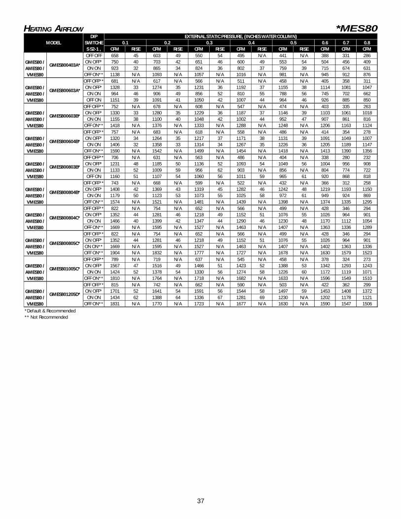


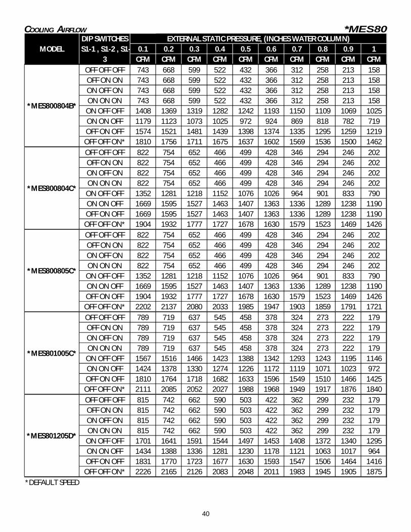
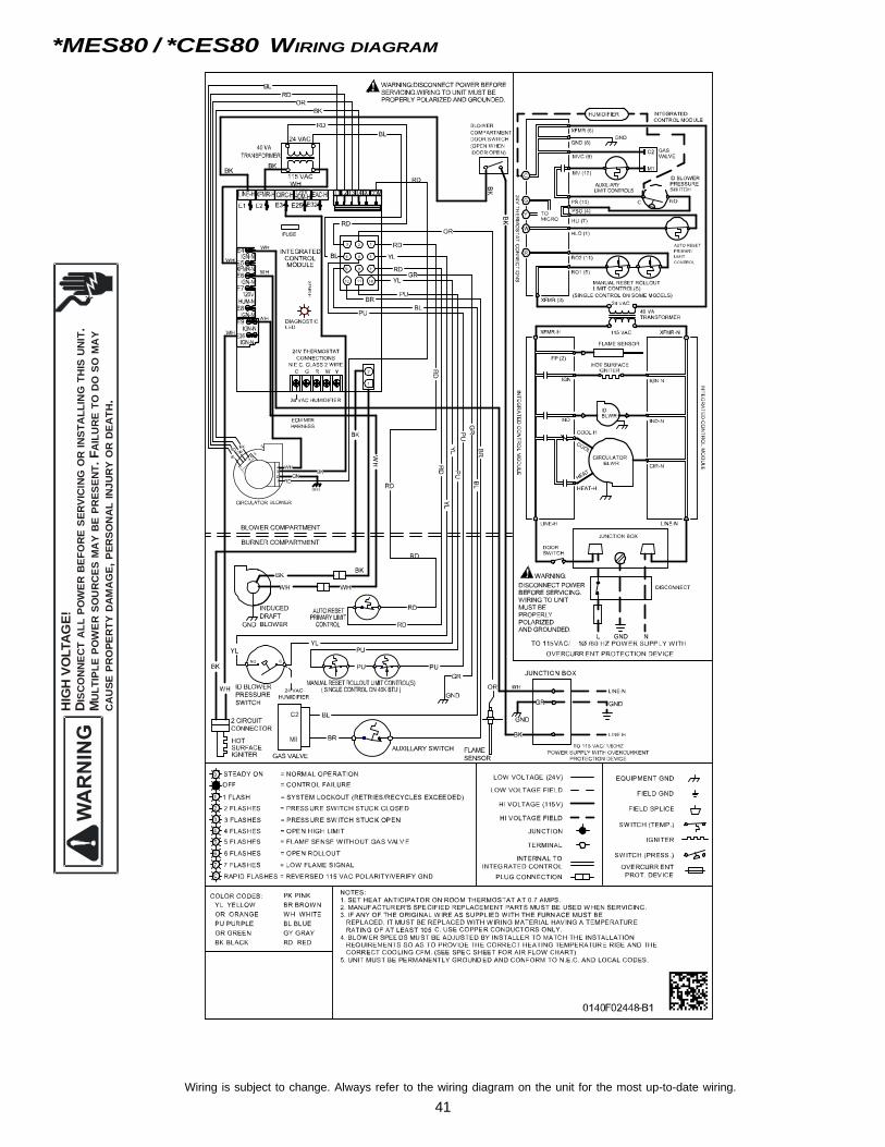


![The composition function k(x) = (f o g)(x) = f (g(x)) g f g f R->[0,+oo)->[-1, 1]](https://static.documents.pub/doc/80x56/56649f1f5503460f94c36d59/the-composition-function-kx-f-o-gx-f-gx-g-f-g-f-r-0oo-1.jpg)

