31
10920 Madison Avenue · Cleveland, Ohio 44102 · (216) 281-1100 · FAX (216) 281-0228 e-mail: [email protected] web site: www.meriam.com ACCUTUBE INSTALLATION INSTRUCTIONS File No. 957:440-11

10920 Madison Avenue · Cleveland, Ohio 44102 · (216) 281-1100 · FAX (216) 281-0228e-mail: [email protected] web site: www.meriam.com
ACCUTUBE
INSTALLATIONINSTRUCTIONS
File No. 957:440-11

2
ACCUTUBE INSTALLATION INSTRUCTIONS
CONTENTS PAGE
ACCUTUBE MODEL NO. CONFIGURATOR................................................................3
ACCUTUBE MODELS .....................................................................................................4
1 SYSTEM CONSIDERATIONS.........................................................................................5
2 OPERATIONAL CONSIDERATIONS.............................................................................9
3 READOUT INSTRUMENTATION ..................................................................................9
4 INSTALLATION PROCEDURE ......................................................................................9
4.1 GENERAL REQUIREMENTS.................................................................................9
4.2 SERIES 10A, 11A, & 12A ......................................................................................10
4.3 SERIES 20T, 21T, 22L, 23L, 40H, 41H, 42H & 43H.............................................11
4.4 SERIES 24D & 25D ................................................................................................12
4.5 SERIES 33T INSTALLATION ..............................................................................13
4.6 PROBE REMOVAL................................................................................................15
4.7 SERIES 37L, 70H & 72H INSTALLATION..........................................................154.7.1 EQUIPMENT REQUIRED ..........................................................................154.7.2 INSTALLATION – ½” AND 1” DIA. PROBES W / SOCKET DRIVE.....154.7.3 INSTALLATION – ½” AND 1” DIA. PROBES W / GEAR DRIVE .........174.7.4 INSTALLATION – 2 3/8” DIA. PROBES W / SOCKET DRIVE..............184.7.5 INSTALLATION – 2 3/8” DIA. PROBES W / GEAR DRIVE...................204.7.6 SPECIAL DOUBLE-SUPPORT INSTRUCTIONS.....................................214.7.7 RECTRACTION PROCEDURE FOR SOCKET DRIVE UNITS...............224.7.8 RECTRACTION PROCEDURE FOR GEAR DRIVE UNITS ...................23
4.8 DIRECT TRANSMITTER MOUNT HEADS WITH EQUALIZING VALVES...24 AND INTEGRAL RTD OPTION, SERIES 40H – 43H, 70H & 72H
4.9 SPECIAL APPLICATIONS (DUCTS/SADDLE CLAMPS/ROTATED HEAD)..25
5 OPERATIONS .................................................................................................................26
6 INTERCHANGEABILITY..............................................................................................27
7 MAINTENANCE & REPLACEMENT PARTS .............................................................28
8 TROUBLESHOOTING ...................................................................................................28
9 CALCULATIONS & FLOW COEFFICIENTS......................................................... 29-31
ACCUTUBE MODEL NUMBER CONFIGURATOR
3
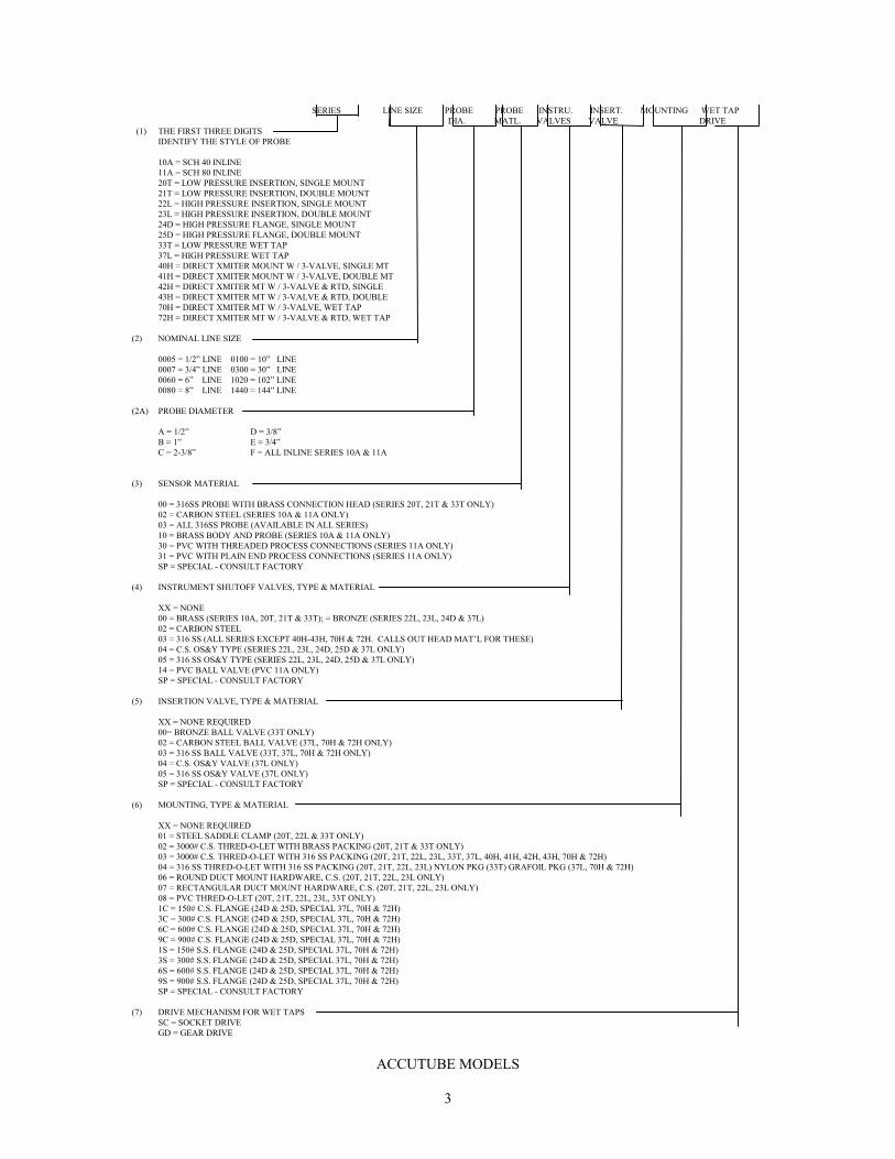
SERIES LINE SIZE PROBE PROBE INSTRU. INSERT. MOUNTING WET TAP DIA. MATL. VALVES VALVE DRIVE (1) THE FIRST THREE DIGITS
IDENTIFY THE STYLE OF PROBE
10A = SCH 40 INLINE11A = SCH 80 INLINE20T = LOW PRESSURE INSERTION, SINGLE MOUNT21T = LOW PRESSURE INSERTION, DOUBLE MOUNT22L = HIGH PRESSURE INSERTION, SINGLE MOUNT23L = HIGH PRESSURE INSERTION, DOUBLE MOUNT24D = HIGH PRESSURE FLANGE, SINGLE MOUNT25D = HIGH PRESSURE FLANGE, DOUBLE MOUNT33T = LOW PRESSURE WET TAP37L = HIGH PRESSURE WET TAP40H = DIRECT XMITER MOUNT W / 3-VALVE, SINGLE MT41H = DIRECT XMITER MOUNT W / 3-VALVE, DOUBLE MT42H = DIRECT XMITER MT W / 3-VALVE & RTD, SINGLE43H = DIRECT XMITER MT W / 3-VALVE & RTD, DOUBLE70H = DIRECT XMITER MT W / 3-VALVE, WET TAP72H = DIRECT XMITER MT W / 3-VALVE & RTD, WET TAP
(2) NOMINAL LINE SIZE
0005 = 1/2” LINE 0100 = 10” LINE0007 = 3/4” LINE 0300 = 30” LINE0060 = 6” LINE 1020 = 102” LINE0080 = 8” LINE 1440 = 144” LINE
(2A) PROBE DIAMETER
A = 1/2” D = 3/8”B = 1” E = 3/4”C = 2-3/8” F = ALL INLINE SERIES 10A & 11A
(3) SENSOR MATERIAL
00 = 316SS PROBE WITH BRASS CONNECTION HEAD (SERIES 20T, 21T & 33T ONLY)02 = CARBON STEEL (SERIES 10A & 11A ONLY)03 = ALL 316SS PROBE (AVAILABLE IN ALL SERIES)10 = BRASS BODY AND PROBE (SERIES 10A & 11A ONLY)30 = PVC WITH THREADED PROCESS CONNECTIONS (SERIES 11A ONLY)31 = PVC WITH PLAIN END PROCESS CONNECTIONS (SERIES 11A ONLY)SP = SPECIAL - CONSULT FACTORY
(4) INSTRUMENT SHUTOFF VALVES, TYPE & MATERIAL
XX = NONE00 = BRASS (SERIES 10A, 20T, 21T & 33T); = BRONZE (SERIES 22L, 23L, 24D & 37L)02 = CARBON STEEL03 = 316 SS (ALL SERIES EXCEPT 40H-43H, 70H & 72H. CALLS OUT HEAD MAT’L FOR THESE)04 = C.S. OS&Y TYPE (SERIES 22L, 23L, 24D, 25D & 37L ONLY)05 = 316 SS OS&Y TYPE (SERIES 22L, 23L, 24D, 25D & 37L ONLY)14 = PVC BALL VALVE (PVC 11A ONLY)SP = SPECIAL - CONSULT FACTORY
(5) INSERTION VALVE, TYPE & MATERIAL
XX = NONE REQUIRED00= BRONZE BALL VALVE (33T ONLY)02 = CARBON STEEL BALL VALVE (37L, 70H & 72H ONLY)03 = 316 SS BALL VALVE (33T, 37L, 70H & 72H ONLY)04 = C.S. OS&Y VALVE (37L ONLY)05 = 316 SS OS&Y VALVE (37L ONLY)SP = SPECIAL - CONSULT FACTORY
(6) MOUNTING, TYPE & MATERIAL
XX = NONE REQUIRED01 = STEEL SADDLE CLAMP (20T, 22L & 33T ONLY)02 = 3000# C.S. THRED-O-LET WITH BRASS PACKING (20T, 21T & 33T ONLY)03 = 3000# C.S. THRED-O-LET WITH 316 SS PACKING (20T, 21T, 22L, 23L, 33T, 37L, 40H, 41H, 42H, 43H, 70H & 72H)04 = 316 SS THRED-O-LET WITH 316 SS PACKING (20T, 21T, 22L, 23L) NYLON PKG (33T) GRAFOIL PKG (37L, 70H & 72H)06 = ROUND DUCT MOUNT HARDWARE, C.S. (20T, 21T, 22L, 23L ONLY)07 = RECTANGULAR DUCT MOUNT HARDWARE, C.S. (20T, 21T, 22L, 23L ONLY)08 = PVC THRED-O-LET (20T, 21T, 22L, 23L, 33T ONLY)1C = 150# C.S. FLANGE (24D & 25D, SPECIAL 37L, 70H & 72H)3C = 300# C.S. FLANGE (24D & 25D, SPECIAL 37L, 70H & 72H)6C = 600# C.S. FLANGE (24D & 25D, SPECIAL 37L, 70H & 72H)9C = 900# C.S. FLANGE (24D & 25D, SPECIAL 37L, 70H & 72H)1S = 150# S.S. FLANGE (24D & 25D, SPECIAL 37L, 70H & 72H)3S = 300# S.S. FLANGE (24D & 25D, SPECIAL 37L, 70H & 72H)6S = 600# S.S. FLANGE (24D & 25D, SPECIAL 37L, 70H & 72H)9S = 900# S.S. FLANGE (24D & 25D, SPECIAL 37L, 70H & 72H)SP = SPECIAL - CONSULT FACTORY
(7) DRIVE MECHANISM FOR WET TAPSSC = SOCKET DRIVEGD = GEAR DRIVE
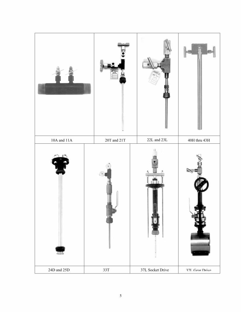
ACCUTUBE MODELS
5
10A and 11A 20T and 21T 40H thru 43H
24D and 25D 33T 37L Socket Drive
22L and 23L
37L Gear Drive
6
1 SYSTEM CONSIDERATIONS
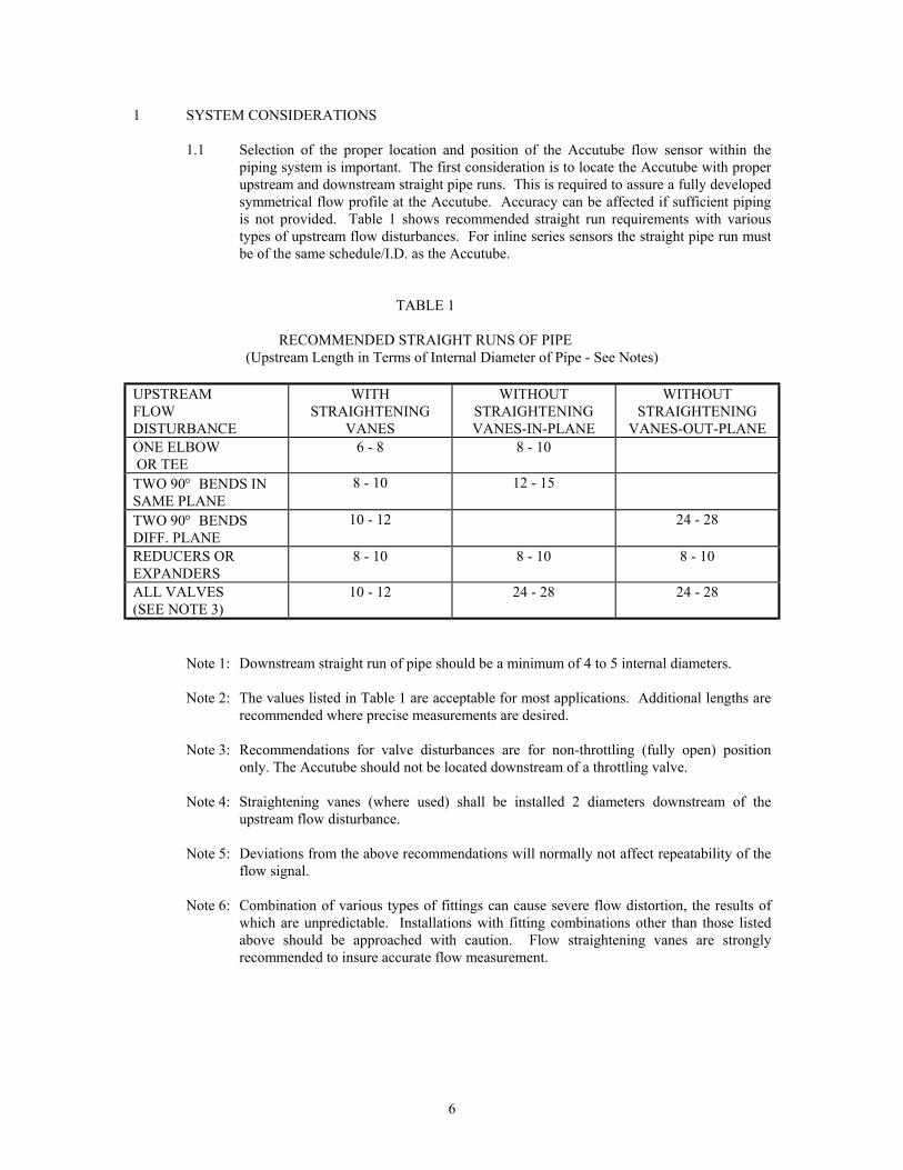
1.1 Selection of the proper location and position of the Accutube flow sensor within thepiping system is important. The first consideration is to locate the Accutube with properupstream and downstream straight pipe runs. This is required to assure a fully developedsymmetrical flow profile at the Accutube. Accuracy can be affected if sufficient pipingis not provided. Table 1 shows recommended straight run requirements with varioustypes of upstream flow disturbances. For inline series sensors the straight pipe run mustbe of the same schedule/I.D. as the Accutube.
TABLE 1
RECOMMENDED STRAIGHT RUNS OF PIPE (Upstream Length in Terms of Internal Diameter of Pipe - See Notes)
UPSTREAMFLOWDISTURBANCE
WITHSTRAIGHTENING
VANES
WITHOUTSTRAIGHTENINGVANES-IN-PLANE
WITHOUTSTRAIGHTENING
VANES-OUT-PLANEONE ELBOW OR TEE
6 - 8 8 - 10
TWO 90° BENDS INSAME PLANE
8 - 10 12 - 15
TWO 90° BENDSDIFF. PLANE
10 - 12 24 - 28
REDUCERS OREXPANDERS
8 - 10 8 - 10 8 - 10
ALL VALVES(SEE NOTE 3)
10 - 12 24 - 28 24 - 28
Note 1: Downstream straight run of pipe should be a minimum of 4 to 5 internal diameters.
Note 2: The values listed in Table 1 are acceptable for most applications. Additional lengths arerecommended where precise measurements are desired.
Note 3: Recommendations for valve disturbances are for non-throttling (fully open) positiononly. The Accutube should not be located downstream of a throttling valve.
Note 4: Straightening vanes (where used) shall be installed 2 diameters downstream of theupstream flow disturbance.
Note 5: Deviations from the above recommendations will normally not affect repeatability of theflow signal.
Note 6: Combination of various types of fittings can cause severe flow distortion, the results ofwhich are unpredictable. Installations with fitting combinations other than those listedabove should be approached with caution. Flow straightening vanes are stronglyrecommended to insure accurate flow measurement.

7
1.2 Determine the position of the Accutube and indicating instrument with respect to thepipe. Selection of the entry location (i.e. in from top or bottom, etc.) is determined byconsidering the fluid in the pipe. Sections 1.2.1 through 1.2.4 give general requirementsfor Accutube position and installation, and specific recommendations for each generalcategory of fluid (1.2.1-Liquid; 1.2.2-Gas; 1.2.3-Steam; 1.2.4-General Requirement).
1.2.1 LIQUID FLOW METERING
1.2.1.1 With liquid flow the readout instrument is normally located below the
Accutube. This prevents air entrapment in the instrument lines.Figures 1.1 through 1.4 show recommended orientation for liquid flow.
1.2.1.2 See Section 1.2.4 General Interconnection Requirements.
1.2.1.3 Instrument lines should be properly sloped (1/2” per foot) without
high points that may cause air entrapment. If this is not possible, airvent valves must be placed at any high points in piping. Trapped air isa frequent cause for measurement error with liquids. Refer to Figs. 1.1thru 1.4.
1.2.1.4 The air vent valves should be bled on a regular basis during normal
operation and upon restart after a system shutdown.
1.2.2 GAS FLOW METERING
1.2.2.1 Few restrictions apply to system arrangement in dry gas flow. Figures1.1, 1.2 and 1.5 are recommended for simplicity in installation.
1.2.2.2 For installations where condensation or entrained liquids accumulate in
the instrument piping, it is recommended that the instrument bemounted above the Accutube or install the Accutube in the top portionof the line. If mounting the instrument below the Accutube isnecessary, then sediment traps and/or drain valves should be used as inFigure 1.6.
1.2.2.3 See Section 1.2.4 for General Interconnection Requirements.
1.2.3 STEAM FLOW APPLICATIONS
1.2.3.1 As in liquid flow, the indicator should be located below the Accutube.
Figure 1.1 shows the recommended configuration. This configurationallows condensate to collect in instrument lines and finds its naturallevel within the Accutube. See Figure 1.4 for top entry (probe) inhorizontal lines.
1.2.3.2 An installation in a vertical pipe should only be performed when a
horizontal line location is not available. This installation should be asin Figure 1.2. A special “rotated head” Accutube is normally used.This permits side port connection, allowing installation similar toFigure 1.2.
1.2.3.3 See Section 1.2.4 for General Interconnection Requirements.

7
8
The indicator must be placed far enough away from the Accutube to prevent thermal damage from lineheat. Allow 1 ft. of uninsulated instrument piping for every 100° F of process temperature.
1.2.3.4 Slope the instrument lines to probe at an incline of approximately 1/2”per foot to prevent air entrapment.
WARNING: DO NOT ATTEMPT TO FILL INSTRUMENT LINESIF SYSTEM CONNECTING LINES ARE UNDER PRESSURE.
1.2.3.5 Fill the instrument lines with water before connecting the Accutube oropening block valves.
1.2.3.6 Allow approximately 1/2 hour after system startup for condensate level
to stabilize. Stabilization time may be reduced by section 1.2.3.5above.
1.2.3.7 Accutubes should not be used for steam applications when the
differential pressure is less than 10” water column.
1.2.4 GENERAL INTERCONNECTION REQUIREMENTS
1.2.4.1 Instrument lines to the Accutube shall be as large as possible in liquidand steam applications. For Accutube with 1/2” NPT connections,1/2” pipe or tubing is recommended. Accutubes with 1/8” NPTconnections should use 1/4” pipe or tubing.
1.2.4.2 Use of the optional instrument shutoff valves at the Accutube head are
recommended.
1.2.4.3 Use of a 3-valve manifold is recommended at the indicator to aidsystem startup and to ease indicator maintenance and calibration.
1.2.4.4 Where instrument-piping slopes are required, use 1/2” per foot
minimum.
1.2.4.5 The length of the instrument lines does not affect accuracy. Long linescan, however, dampen the indicator response time.
1.2.4.6 Test the system for leaks after connecting instrumentation to assure that
no leaks exist.
1.2.4.7 In situations where accumulation of sediment or condensation withinthe piping is possible, a system drain or pressure blow down should beperformed on a regular basis. Valves are recommended forindicators/transmitters without drain valves/plug.

9
2 OPERATIONAL CONSIDERATIONS
2.1 The Accutube flow sensor is a bi-directional flow meter. It can measure flow in eitherdirection. The Accutube head is labeled High and Low pressure as observed for normalflow directions. With reverse flow, the High-pressure signal will occur at the Low-pressure port and vice versa. Reverse flow measurement is as precise as forward flow.This unique feature allows measurement of flow that changes direction. Specialconsideration should be given to the indicating instrument. Instruments which allowpositive and negative (zero center) differential pressure readings are best applied here.
2.2 Accutube probes have limits as to the maximum flow rate that can be tolerated without
risking damage to the sensor. The limits are defined as the maximum allowabledifferential pressure. See the Accutube general catalog which lists the maximumallowable differential pressures for your Accutube model.
2.3 Installation of the Accutube in locations where significant pipe vibrations exist should be
avoided. Double mount style Accutubes are recommended where vibration is a concern. 3 READOUT INSTRUMENTATION
3.1 Many types of readout instrumentation can be used to measure the Accutube differentialpressure. The most common types are manometers, dial gauge indicators, electronictransmitters/transducers or electronic gauges. Each type has its own installation andoperational characteristics. Refer to manufacturer’s manuals for installation instructions.
3.2 Mounting position can affect zero indication on certain types of instruments. In such
cases, the zero setting should be adjusted after installation of the instrument.
3.3 When a mercury manometer is used with a steam or liquid flow a correction factor mustbe applied to the flow calculations. Refer to Handbook, File No. 957:081, fordetermining the correction factor.
4 INSTALLATION PROCEDURE
4.1 GENERAL REQUIREMENTS
4.1.1 Prepare the surface of the pipe or duct where the Accutube is to be mounted.Proper preparation involves removal of scale, rust, paint and grease for properwelding of the threaded coupling.
4.1.2 Drill or burn a hole through the pipe at the mounting location. The hole should
be 1/16" to 1/8" larger than the probe diameter as identified in Table 4.
TABLE 4
PROBEDIAMETER
RECOMMENDEDDRILL SIZE
3/8 7/161/2 9/163/4 13/161 1-1/16
2-3/8 2-1/2

10
4.1.3 Double support type sensors require a second hole on the opposite side of thepipe. Location of this hole is important as it establishes proper alignment of theprobe with respect to the flow. A common method of locating the oppositesupport hole is by wrapping a piece of string totally around the pipe, with thestring crossing square to the pipe. The position can be marked at 1/2 the totallength of the string.
4.1.4 Center the threaded weld coupling over the hole and tack weld in place.
4.1.5 Thread the packing gland fitting in place (compression type), and insert the
probe into the pipe. Observe the position of the probe assuring that it isperpendicular within the tolerance shown in Figure 4.1. If adjustments arerequired, remove the probe and packing, and thread a pipe into the threadedfitting a few feet long. With the leverage of the pipe force the threaded fittinginto the proper position.
DO NOT TRY TO USE THE ACCUTUBE AS A LEVER. DAMAGE TO THE PROBE AND/OR PACKING CAN RESULT!
4.1.6 Once alignment is verified, perform a final weld of the threaded fitting.
4.1.7 Re-assemble the packing and insert the Accutube as described in Section 4.3.
FIGURE 4.1 ACCUTUBE PROBE POSITIONING(Maximum Allowable Misalignment)
4.2 INLINE FLOW SENSORS: SERIES 10A, 11A & 12A
4.2.1 The inline series flow sensors are flow-through devices in which the line mustbe interrupted for the device to be installed.
4.2.2 Positioning of the sensor is the same as recommended for the other types of
sensors as listed in Section 1.0.
4.2.3 Connections to the main line are made through either threaded pipe fittings,solvent cement for PVC plain end type, hose connections for plain end types, orsoldered joint for copper tube units.

11
4.2.4 Series 10A and 11A inline sensors are bi-directional devices. They can beinstalled with flow in either direction through the unit. The Series 12A must beinstalled with the balancing valve downstream of the metering section.
4.3 INSERTION FLOW SENSORS, COMPRESSION FITTING: SERIES 20T, 21T, 22L, 23L, 40H, 41H, 42H & 43H 4.3.1 Perform the general preparation steps as outlined in Section 4.1.1 through 4.1.6. 4.3.2 Slide fitting nut onto the probe with the threaded end facing the tip of the probe.
4.3.3 Slide the ferrule onto the probe so that the angle of the taper slopes downward
toward the probe tip.
4.3.4 With the fitting body already assembled and tightened onto the threadedcoupling, insert the probe into the line.
4.3.5 Slide the ferrule into the fitting body.
4.3.6 Thread the nut onto the fitting body finger-tight.
4.3.7 Properly position the probe so that the High-pressure connection (side
connection) is pointing upstream within the tolerances as shown in Figure 4.1.
4.3.8 Withdraw the probe tip from the opposite end of the pipe 1/16” for line size 12”and smaller, and 1/8” for larger lines sizes. This step properly locates thesensing port holes and allows for thermal expansion of the probe.
4.3.8.1 The Series 21T, 23L, 41H & 43H double support Accutubes include a
specially machined support plug. Be sure that the flow sensor is fullyinserted into this plug and not simply resting on top. Rotating theprobe and/or the plug while inserting the probe will aid in alignment.Be sure to retighten the plug and provide clearance as listed in 4.3.8.
4.3.9 Tighten the nut with a wrench an additional number of turns as follows. Hold
the fitting body with a second wrench to prevent the body from turning. It ishelpful to mark the nut to facilitate counting the number of turns.
CAUTION: DO NOT OVERTIGHTEN!
Sealing turns from hand-tight required Stainless steel fittings on probe
3/8” through 1” O.D............................................1-1/4 turns
Brass fittings on probe diameters
3/8” and 3/4”.......................................................2-1/4 turns

12
4.3.10 For maximum number of remakes, mark the fitting and nut (scribe or ink)before disassembly. Remake by tightening until marks line up again. A slighttorque rise will be felt indicating the ferrule is being re-sprung into sealingposition. Only after several remakes may it become necessary to advance thenut slightly past original position. This advance need only be 10° - 20° (lessthan 1/3 of a hex flat).
4.3.11 The Accutube is now prepared for instrument connection and operation.
4.4 INSERTION FLOW SENSORS, FLANGE MOUNT: SERIES 24D & 25D
4.4.1 Perform general preparation as listed in Sections 4.1.1 through 4.1.4. Note thatwith this series, a weld coupling, not a threaded coupling is used for mounting.In the case of Series 25D the opposite end support is still a threaded coupling.
4.4.2 Place the weld neck flange on top the welded coupling and verify that the
dimension A is as shown in Figure 4.2. This dimension establishes the positionof the sensing ports within the pipe and allows for thermal expansion of theprobe. The allowable tolerance is + 1/16”, -0”.
FIGURE 4.2 24D/25D MOUNTING HEIGHT FOR 150lb FLANGE
4.4.3 Tack weld the weld neck flange onto the Weld-O-Let so that the four holes onthe flange straddle the pipe centerline. An imaginary line drawn through anytwo adjacent holes should run parallel to pipe centerline or perpendicular to it.Refer to Figure 4.3.
FIGURE 4.3 24D/25D FLANGE ORIENTATION
Probe Dia. 1/2” 1” 2-3/8”
A + 1/16
- 0
3-1/2 3-1/2 4-3/8

13
4.4.4 Place the gasket on top of the weld neck flange and insert the Accutube to verifyalignment of the probe and clearance. Alignment of the probe must be withinthe limits shown in Figure 4.1. The probe tip should clear the inside wall of thepipe by 1/16” on 12” and smaller line sizes, and 1/8” on larger line sizes (thisclearance will occur within the support plug on Series 25D (see 4.4.5). Adjustthe position of the Weld -O-Let and weld neck flange, if necessary, to provideproper orientation of the probe to the pipe. Align the probe flange boltholeswith those on the weld neck flange and verify that the flow direction arrowstamped on the probe flange points in the proper direction.
4.4.5 For Series 25D the end support must now be positioned. Assemble the support
plug into the threaded coupling. With the Accutube properly positioned, slipthe threaded coupling over the probe tip and engage the support plug. Tackweld the threaded coupling in place.
4.4.6 Complete the welding of the Weld-O-Let and the weld neck flange (also Thred-
O-Let in case of opposite side supported model 25D).
4.4.7 Again assemble gasket and insert probe in place observing flow arrow direction.
4.4.8 Use a flat washer with each nut and bolt. First hand-tighten each bolt. Use acriss-cross or star pattern to tighten bolts. Check bolt tightness 24 hours afterinstallation.
4.4.9 The Accutube is now prepared for instrument connection and operation.
4.5 LOW PRESSURE WET TAP: SERIES 33T
4.5.1 Verify that the operating pressure and temperature are within the published limitof the Accutube, probe valves, and mounting assembly. Refer to Table 5.
4.5.2 Prepare the pipe surface for welding and tack weld the Thred-O-Let to the pipe.
Verify alignment of the Thred-O-Let and finish the weld (see Section 4.1).
4.5.3 Assemble the support nipple (3/4” probes), chain hook and the insertion valve.Pipe sealant/dope is recommended on all pipe threads on the mountingassembly. Be sure that the insertion valve is in the fully open position. Be surethe chain hook is in place between the Thred-O-Let and the insertion valve.
4.5.4 Assemble the packing gland fitting onto the valve. The fitting need only be
hand tightened and the ferrule need not be in place at this time.
4.5.5 Slide the punch through the fitting until it touches the pipe (diameter of theguide punch must be the same diameter as the Accutube). Specially machinedpunches and drills are required. These are available from Meriam.
4.5.6 Impact the punch to leave the impression on the pipe to aid in starting the drill.
4.5.7 Remove the punch and the packing gland fitting from the insertion valve.
4.5.8 Insert the drill through the insertion valve and reassemble the packing ferrule
and nut around the drill shank.NOTE: The tapered end of the ferrule slips into the packing gland fitting body.

14
4.5.9 Lightly wrench-tighten the nut in place. Double check that all connections aretight and the insertion valve is fully open.
4.5.10 Mount the drill motor onto the drill and penetrate the pipe. The mounting
assembly is now pressurized.
4.5.11 Retract the drill bit until it stops against the packing gland fitting anddisassemble the drill motor from the drill bit.
4.5.12 Close the valve. 4.5.13 Slowly loosen the packing gland fitting to vent any pressure. Remove drill bit. 4.5.14 Assemble the reducing bushing (on 3/4” probe only) and cage pipe onto the
insertion valve.
4.5.15 Assemble the pipe coupling onto the end of the cage pipe.
4.5.16 Assemble the packing gland fitting onto the pipe coupling. Be sure that theferrule is in place with the taper end into the body of the fitting and the nut looseon the fitting body. All other joints should be wrench-tight.
4.5.17 Insert the Accutube probe into the packing gland fitting and slide down until the
tip meets the insertion valve. 4.5.18 Lightly wrench-tighten the compression nut onto the Accutube probe. 4.5.19 Attach the safety chain to the head of the Accutube probe and to the chain hook
located on the bottom side of the insertion valve. There should be little slack inthe chain. This chain is an imperative safety measure to prevent the Accutubeprobe from accidentally being forced out of the assembly under pressure.
4.5.20 Verify that both instrument valves are fully closed. 4.5.21 Open the insertion valve fully. The entire system is again pressurized including
the Accutube probe. Any leakage at the compression gland fitting can becorrected by further tightening the packing gland nut.
4.5.22 Manually push the probe in through the mounting assembly until the tip touches
the opposite wall of the pipe.
4.5.23 Retract the probe 1/16” on line sizes 12” and less, and 1/8” for larger line sizes.This measure properly locates the sensing port holes and allows for thermalexpansion of the probe. Align the probe so that the side head connection pointsinto the flow.
4.5.24 Tighten the nut on the packing gland fitting two turns from the hand-tight/light
wrench position for final sealing/holding capability.
DO NOT OVER TIGHTEN! PROBE DAMAGE CAN RESULT FROMOVERTIGHTENING.
4.5.25 Readjust the chain position so that the chain is taut in this fully inserted position.

15
4.5.26 Verify the alignment of the probe head with respect to the pipe line. The sidepressure port should point directly upstream. Refer to Figure 4.1
4.5.27 The Accutube is now ready to be placed into operation.
4.6 PROBE REMOVAL 4.6.1 Close the high and Low-pressure instrument valves. 4.6.2 Disconnect or modify line connections to head to allow probe removal. 4.6.3 As a precaution, hold the probe in place and adjust the safety chain to allow 2
links of slack.
4.6.4 Still holding the probe loosen the packing gland fitting nut slowly until theprobe can be withdrawn.
4.6.5 Withdraw the probe until the chain tightens. Retighten the packing nut. 4.6.6 Gently attempt to close the insertion valve. If the probe prevents if from
closing, adjust the chain to allow 2 additional links of slack. Remove the probefurther and again attempt to close the valve. Repeat this as necessary.
4.6.7 With the valve closed, there is still residual pressure in the upper portion of the
assembly. This can be relieved by venting either or both of the valves on theAccutube head.
4.6.8 The probe can now be fully removed.
4.7 HIGH PRESSURE WET-TAP: SERIES 37L, 70H & 72H 4.7.1 EQUIPMENT REQUIRED:
4.7.1.1 Accutube probe with all wet tap mounting hardware.
4.7.1.2 Instrument valves (1/2” NPT) to be assembled onto the probe.
4.7.1.3 Pressurized drilling equipment - suggested source is Mueller Co.
(Decatur, Ill.) Model D-5 or DH-5 with necessary drill holder andadapter nipple to attach to 3/4” FNPT for the 1/2” diameter probe, 1-1/4” FNPT for the 1” diameter probe, and 3” - 150 lb. flanges for the 2-3/8” diameter probe. See Table 4 for drill size required.
4.7.1.4 Welding Equipment.
4.7.1.5 Standard pipe wrenches and hex wrenches.
4.7.2 INSTALLATION PROCEDURE - 1/2” AND 1” DIAMETER PROBES WITHSOCKET DRIVE
4.7.1.1 Verify that the operating pressure and temperature are within the Accutube probe, and valve limitations. Refer to Table 5.
4.7.1.2 In determining probe installation, a vertical probe position, eitherabove or below the pipe is recommended for 12” line size and greaterdue to the assembly weight extending to the side. Support of the
16
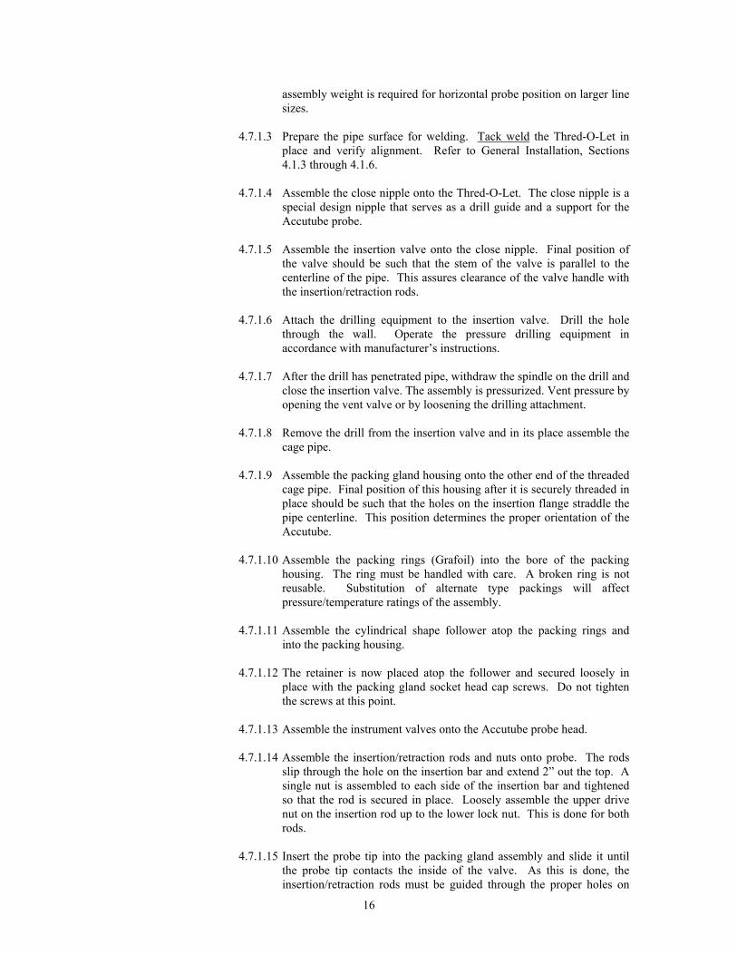
assembly weight is required for horizontal probe position on larger linesizes.
4.7.1.3 Prepare the pipe surface for welding. Tack weld the Thred-O-Let in
place and verify alignment. Refer to General Installation, Sections4.1.3 through 4.1.6.
4.7.1.4 Assemble the close nipple onto the Thred-O-Let. The close nipple is a
special design nipple that serves as a drill guide and a support for theAccutube probe.
4.7.1.5 Assemble the insertion valve onto the close nipple. Final position ofthe valve should be such that the stem of the valve is parallel to thecenterline of the pipe. This assures clearance of the valve handle withthe insertion/retraction rods.
4.7.1.6 Attach the drilling equipment to the insertion valve. Drill the hole
through the wall. Operate the pressure drilling equipment inaccordance with manufacturer’s instructions.
4.7.1.7 After the drill has penetrated pipe, withdraw the spindle on the drill andclose the insertion valve. The assembly is pressurized. Vent pressure byopening the vent valve or by loosening the drilling attachment.
4.7.1.8 Remove the drill from the insertion valve and in its place assemble the
cage pipe. 4.7.1.9 Assemble the packing gland housing onto the other end of the threaded
cage pipe. Final position of this housing after it is securely threaded inplace should be such that the holes on the insertion flange straddle thepipe centerline. This position determines the proper orientation of theAccutube.
4.7.1.10 Assemble the packing rings (Grafoil) into the bore of the packing
housing. The ring must be handled with care. A broken ring is notreusable. Substitution of alternate type packings will affectpressure/temperature ratings of the assembly.
4.7.1.11 Assemble the cylindrical shape follower atop the packing rings and
into the packing housing. 4.7.1.12 The retainer is now placed atop the follower and secured loosely in
place with the packing gland socket head cap screws. Do not tightenthe screws at this point.
4.7.1.13 Assemble the instrument valves onto the Accutube probe head. 4.7.1.14 Assemble the insertion/retraction rods and nuts onto probe. The rods
slip through the hole on the insertion bar and extend 2” out the top. Asingle nut is assembled to each side of the insertion bar and tightenedso that the rod is secured in place. Loosely assemble the upper drivenut on the insertion rod up to the lower lock nut. This is done for bothrods.
4.7.1.15 Insert the probe tip into the packing gland assembly and slide it until
the probe tip contacts the inside of the valve. As this is done, theinsertion/retraction rods must be guided through the proper holes on
17
the insertion flange of the packing housing. The head of the Accutubeduring this procedure should be oriented so that the flow arrow agreeswith the flow direction within the pipe. During the initial insertion ofthe probe tip into the packing housing, use care not to damage thepacking rings. Assemble the lower drive nuts with washers onto theinsertion/retraction rods. Thread the nuts upward until the washerscontact the insertion flange.
4.7.1.16 Lightly snug the packing gland socket head cap screws just enough toset the packing in place and remove any clearances. Turn the hexsocket head cap screws each 1-1/4 turns to pre-load the packing rings.Turn the screws a small amount alternately so as to tighten theassembly slowly and evenly from both sides.
4.7.1.17 Verify the instrument valves on the Accutube head are closed. 4.7.1.18 Open the insertion valve. Verify all joints and packing are sealed
tightly as the entire assembly is now pressurized. The packingassembly can be tightened further if required.
4.7.1.19 Insert the probe into pipeline by turning the lower drive nut counter
clockwise to pull the Accutube probe into the line. Both lower drivenuts should be turned alternately so as to prevent uneven loading andjamming of the Accutube assembly. Use this procedure until the probetouches and stops on the opposite side of the pipe.
4.7.1.20 Withdraw the probe from the opposite end of the pipe wall 1/16” on
12” line size and less, or 1/8” on larger line sizes. This clearance is aprovision for thermal expansion allowances and assures centering portholes.
4.7.1.21 Again inspect the packing gland assembly for leakage. If required,
tighten the packing screws an additional amount. 4.7.1.22 The Accutube is now in working condition.
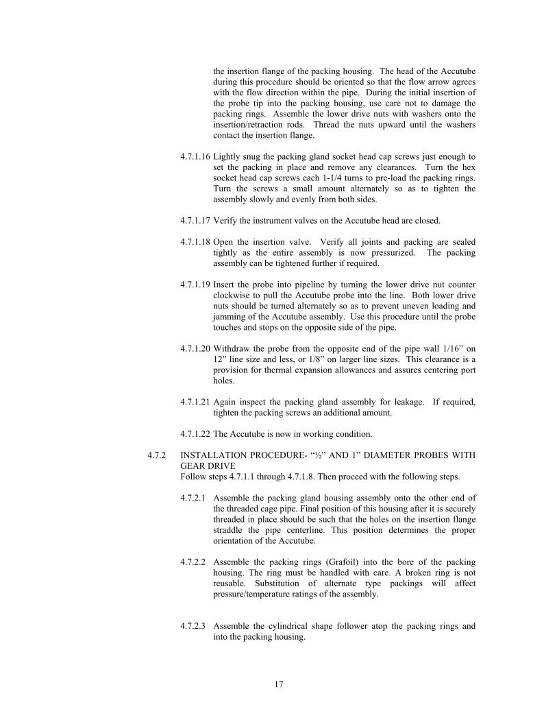
4.7.2 INSTALLATION PROCEDURE- “½” AND 1” DIAMETER PROBES WITHGEAR DRIVEFollow steps 4.7.1.1 through 4.7.1.8. Then proceed with the following steps.
4.7.2.1 Assemble the packing gland housing assembly onto the other end ofthe threaded cage pipe. Final position of this housing after it is securelythreaded in place should be such that the holes on the insertion flangestraddle the pipe centerline. This position determines the properorientation of the Accutube.
4.7.2.2 Assemble the packing rings (Grafoil) into the bore of the packinghousing. The ring must be handled with care. A broken ring is notreusable. Substitution of alternate type packings will affectpressure/temperature ratings of the assembly.
4.7.2.3 Assemble the cylindrical shape follower atop the packing rings andinto the packing housing.
18
4.7.2.4 The retainer is now placed atop the follower and secured loosely inplace with the packing gland socket head cap screws. Do not tightenthe screws at this point.
4.7.2.5 Assemble the instrument valves onto the Accutube probe head.
4.7.2.6 Insert the probe tip into the packing gland assembly. During the initialinsertion, use care not to damage the packing rings. Slide the probethrough the packing until the probe tip contacts the inside of the closedinsertion valve. During this procedure the Accutube head should beoriented so the flow arrow agrees with the flow direction within thepipe. Raise the threaded rods by turning the crank counter clockwiseuntil the rods protrude through the insertion bar. Assemble threadedrods and insertion bar with nuts.
4.7.2.7 Lightly snug the packing gland socket head cap screws just enough toset the packing in place and remove any clearances. Turn the hexsocket head cap screws each 1-1/4 turns to pre-load the packing rings.Turn the screws a small amount alternately so as to tighten theassembly slowly and evenly from both sides.
4.7.2.8 Verify the instrument valves on the Accutube head are closed.
4.7.2.9 Open the insertion valve. Verify all joints and packing are sealedtightly as the entire assembly is now pressurized. The packingassembly can be tightened further if required.
4.7.2.10 Remove locking rod from crank handle.
4.7.2.11 Insert the probe into pipeline by turning the crank handlecounterclockwise to pull the Accutube probe into the line. Use thisprocedure until the probe touches and stops on the opposite side of thepipe.
4.7.2.12 Withdraw the probe from the opposite side of the pipe wall 1/16” on12” line size and less, or 1/8” on larger line sizes. This clearance is aprovision for thermal expansion allowances and assures centering ofport holes.
4.7.2.13 Position crank handle so ¼” threaded hole is visible on lower insertionbar. Insert locking rod.
4.7.2.14 Again inspect the packing gland assembly for leakage. If required,tighten the packing screws an additional amount.
4.7.2.15 The Accutube is now in working condition.
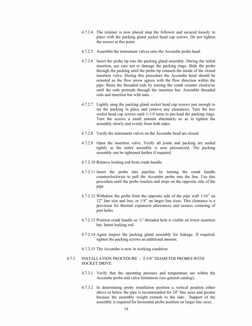
4.7.3 INSTALLATION PROCEDURE - 2-3/8” DIAMETER PROBES WITHSOCKET DRIVE 4.7.3.1 Verify that the operating pressure and temperature are within the
Accutube probe and valve limitations (see general catalog). 4.7.3.2 In determining probe installation position a vertical position either
above or below the pipe is recommended for 24” line sizes and greaterbecause the assembly weight extends to the side. Support of theassembly is required for horizontal probe position on larger line sizes.

19
4.7.3.3 Weld the Weld-O-Let in place in the pipe. The Weld-O-Let is to be
positioned so that it is perpendicular to the centerline of the pipe andsquare to the surface of the pipe. The Weld-O-Let has a specialdesigned I.D. to guide and support the drill and probe.
4.7.3.4 Assemble a weld neck flange onto the Weld-O-Let. Tack weld in place
so that the flange holes straddle the pipe centerline. Verify alignmentand finish the weld.
4.7.3.5 Assemble the insertion valve onto the flange with a gasket in place and
fasten with bolts. Final position should be such that the stem of thevalve is parallel to the centerline of the pipe. This assures clearance ofthe valve handle with the insertion/retraction rod. Use a flat washerwith each bolt and nut. First hand-tighten each bolt. Use a criss-crossor star pattern to tighten bolts. Check tightness 24 hours afterinstallation.
4.7.3.6 Attach the drilling equipment to the insertion valve. Drill size should
be 2-1/2” in diameter. Operate the pressure drilling equipment inaccordance with manufacturer’s instructions.
4.7.3.7 After the drill has penetrated the pipe, withdraw the spindle on the drill
and close the insertion valve. The assembly is pressurized. Open ventvalve on drill or slowly loosen the drilling assembly to vent pressure.
4.7.3.8 Remove the drill from the insertion valve. 4.7.3.9 Weld the weld neck flange to the cage pipe. 4.7.3.10 Weld the packing gland housing onto the opposite end of cage pipe. A
1/16” gap must be left inside the socket of the housing prior towelding. The two insertion rod holes in the lower insertion bar of thepacking gland housing must straddle the bolt holes in the weld neckflanges.
4.7.3.11 Assemble the packing rings (Grafoil) into the bore on the packing
housing. The rings must be handled with care. A broken ring is notreusable. Substitution of alternate type packings will affectpressure/temperature ratings of the assembly.
4.7.3.12 Assemble the cylindrical shape follower atop the packing rings into the
packing housing. 4.7.3.13 The retainer is now placed atop the follower and secured loosely with
the socket head cap screws. Do not tighten the screws at this point. 4.7.3.14 Assemble the packing gland housing/extension subassembly onto the
valve with the remaining gasket located between the flanges. Finalposition of this assembly, when bolted in place should be such that theholes on the lower insertion bar straddle the pipe centerline. Thisposition determines the proper orientation of the Accutube probe whenassembled in place.
4.7.3.15 Assemble the instrument valves onto the Accutube probe head.

20
4.7.3.16 Assemble the insertion/retraction rods and nuts onto the probe. Therods slip through the hole on the upper insertion bar and extend 2” outat the top. A single nut is assembled to each side of the upper insertionbar and tightened so that the rod is locked in place. Loosely assemblethe upper drive nut on the insertion rod up to the lower lock nut. Thisis done for both rods.
4.7.3.17 Insert the probe tip into the packing gland assembly and slide it until
the probe tip contacts the insertion valve. As this is done, theinsertion/retraction rods must be guided through the proper holes onthe lower retraction bar of the packing housing. The head of theAccutube during this procedure should be oriented so that the flowarrow points in the direction of flow. During the initial insertion of theprobe tip into the packing housing, use care not to damage the packingrings. Assemble the lower drive nuts with washers onto theinsertion/retraction rods. Thread the nuts upward until the washerscontact the insertion flange.
4.7.3.18 Lightly snug down the packing gland socket head cap screws just
enough to set the packing in place and remove any clearances. Turnthe hex socket head cap screws an additional 1-1/2 turns to pre-load thepacking rings. Turn the screws a small amount alternately so as totighten the assembly slowly and evenly from both sides.
4.7.3.19 Verify the instrument valves on the Accutube are closed. 4.7.3.20 Open the insertion valve. Verify all joints and packing is sealed tightly
as the entire assembly is now pressurized. The packing assembly canbe tightened further if required.
4.7.3.21 Insert the probe into the pipe. This is done by turning the lower drive
nut (counterclockwise when looking down at the probe) to pull theAccutube into line. Both lower drive nuts should be turned alternatelyso as to prevent uneven loading and jamming of the Accutubeassembly. Use this procedure until the probe touches the opposite sideof the pipe.
4.7.3.22 Withdraw the probe from the opposite end of the pipe wall 1/8”. This
clearance is a provision for thermal expansion. 4.7.3.23 Again inspect the packing gland assembly for leakage. If required,
tighten the packing screws an additional amount. 4.7.3.24 The Accutube is now in working condition.
4.7.4 INSTALLATION PROCEDURE – 2 3/8” DIAMETER PROBES WITH GEARDRIVEFollow steps 4.7.3.1 through 4.7.3.15. Then proceed with the following steps.
4.7.4.1 Insert the probe tip into the packing gland assembly. During the initialinsertion, use care not to damage the packing rings. Slide the probethrough the packing until the probe tip contacts the inside of theinsertion valve. During this procedure the Accutube head should beoriented so the flow arrow agrees with the flow direction within thepipe. Raise the threaded rods by turning the crank counter clockwiseuntil the rods protrude through the insertion bar. Assemble threadedrods and insertion bar with nuts.
21
4.7.4.2 Lightly snug down the packing gland socket head cap screws justenough to set the packing in place and remove any clearances. Turn thehex socket head cap screws an additional 1-1/2 turns to pre-load thepacking rings. Turn the screws a small amount alternately so as totighten the assembly slowly and evenly from both sides.
4.7.4.3 Verify the instrument valves on the Accutube are closed.
4.7.4.4 Open the insertion valve. Verify all joints and packing is sealed tightlyas the entire assembly is now pressurized. The packing assembly canbe tightened further if required.
4.7.4.5 Remove locking rod from crank handle.
4.7.4.6 Insert the probe into the pipe by turning the crank handle counterclockwise to pull the Accutube into the line. Use this procedure untilthe probe touches the opposite side of the pipe.
4.7.4.7 Withdraw the probe from the opposite side of the pipe wall 1/8”. Thisclearance is a provision for thermal expansion and assures centering ofport holes.
4.7.4.8 Position crank handle so ¼” threaded hole on lower insertion bar isvisible. Insert locking rod.
4.7.4.9 Again inspect the packing gland assembly for leakage. If required,tighten the packing screws an additional amount.
4.7.4.10 The Accutube is now in working condition.
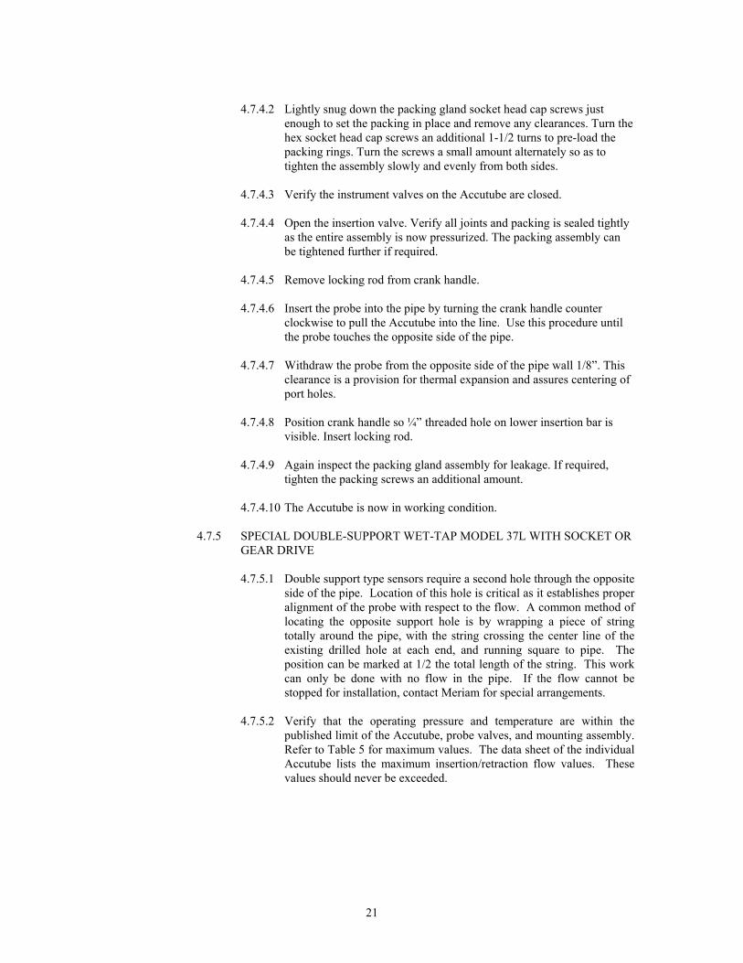
4.7.5 SPECIAL DOUBLE-SUPPORT WET-TAP MODEL 37L WITH SOCKET ORGEAR DRIVE 4.7.5.1 Double support type sensors require a second hole through the opposite
side of the pipe. Location of this hole is critical as it establishes properalignment of the probe with respect to the flow. A common method oflocating the opposite support hole is by wrapping a piece of stringtotally around the pipe, with the string crossing the center line of theexisting drilled hole at each end, and running square to pipe. Theposition can be marked at 1/2 the total length of the string. This workcan only be done with no flow in the pipe. If the flow cannot bestopped for installation, contact Meriam for special arrangements.
4.7.5.2 Verify that the operating pressure and temperature are within the
published limit of the Accutube, probe valves, and mounting assembly.Refer to Table 5 for maximum values. The data sheet of the individualAccutube lists the maximum insertion/retraction flow values. Thesevalues should never be exceeded.
22
4.7.5.3 Double support wet tap Accutubes include a specially machinedinsertion cone on the end of the probe. Be sure that the flow sensor isfully inserted into the opposite side support plug and not simply restingon top. Rotating the probe and/or the plug while inserting the probewill aid in alignment. Be sure to retighten the plug and provideclearance as described in 4.7.2.20 to 4.7.3.22 for socket drive wet tapsor as described in 4.7.3.12 to 4.7.3.15 for gear drive wet taps.
4.7.5.4 All other instructions for the standard models apply.
Job #_______________________________
Item # __________
Model # _____________________________________
Maximum Insertion/Retraction Flow Rate __________
4.7.6 RETRACTION PROCEDURE 1/2”, 1” AND 2-3/8” DIAMETER PROBESWITH SOCKET DRIVE 4.7.6.1 Close both instrument valves on the probe head. 4.7.6.2 Vent/depressurize the instrument connection lines and disconnect from
the probe valves. 4.7.6.3 Retract the probe by rotating the lower drive nuts in a clockwise
direction looking down from the probe head. Rotate each of the nuts asmall amount alternately so that the probe is forced out evenly fromboth sides. If the pipe line pressure is not high enough to force theprobe out of the wet tap assembly as the nuts are rotated, use the upperdrive nuts to force the probe out. If the upper drive nuts are used, thelower drive nuts should be unthreaded down the run rod an inch awayfrom the flange.
4.7.6.4 Continue the retraction of the probe until the lower drive nuts arepositioned on the thread rod 1” from the end of the thread rod.
NEVER UNTHREAD THE LOWER DRIVE NUTS FROM THEROD UNTIL 4.7.7.6 IS COMPLETE!
4.7.6.5 Close the insertion valve. 4.7.6.6 Depressurize the wet tap assembly by cracking open the instrument
valves. A short burst of line fluid will escape from the valves as thewet tap assembly depressurizes.
4.7.6.7 Loosen the packing gland assembly cap screws.
23
4.7.6.8 The Accutube may be left in this position (properly supported)prepared for future insertion or for removal from the wet tap assembly.There are two methods of removing the probe from the wet tapassembly.4.7.6.8.1 Withdraw the probe completely out of the packing gland
assembly and set aside. or
4.7.6.8.2 With the probe still in the wet tap assembly, unthread the cagenipple from the valve (unbolt the flanges in the case of 2-3/8”probe diameter models), treating the cage pipe, packing glandassembly and probe as an assembled unit. When the nipple isremoved from the valve, the entire assembly can be simplylifted and removed. This procedure allows removal of probein situations where minimum overhead clearance is available.
4.7.7 RETRACTION PROCEDURE ½”, 1” AND 2 3/8” DIAMETER PROBES
WITH GEAR DRIVE
4.7.7.1 Close both instrument valves on the probe head.
4.7.7.2 Vent / depressurize the instrument connection lines and disconnectfrom the probe valves.
4.7.7.3 Remove locking rod from crank handle.
4.7.7.4 Retract the probe by rotating the crank handle clockwise.
4.7.7.5 Continue the retraction of the probe until the threaded rods reach theirmechanical stop.
4.7.7.6 Insert locking rod.
4.7.7.7 Close the insertion valve.
4.7.7.8 Depressurize the wet tap assembly by cracking open the instrumentvalves. A short burst of line fluid will escape from the valves as the wettap assembly depressurizes.
4.7.7.9 Loosen the packing gland assembly cap screws.
4.7.7.9.1 Withdraw the probe completely out of the packing glandassembly and set aside.
or
4.7.7.9.2 With the probe still in the wet tap assembly, unthread the cagenipple from the valve (unbolt the flanges in the case of 2-3/8”probe diameter models), treating the cage pipe, packing glandassembly and probe as an assembled unit. When the nipple isremoved from the valve, the entire assembly can be simplylifted and removed. This procedure allows removal of probein situations where minimum overhead clearance is available.
4.8 ACCUTUBES WITH DIRECT DP TRANSMITTER MOUNT INSTRUMENT HEAD,INSERTION MODELS 40H – 43H AND WET TAP MODELS 70H & 72H
24
4.8.1 MODELS 40H, 41H & 70H WITH DIRECT DP TRANSMITTER MOUNTHEAD
4.8.1.1 Refer to previous sections of this manual for Accutube-to-process pipeinstallation instructions.
4.8.1.2 The direct mount instrument head is designed to allow standardindustrial DP transmitters to be bolted directly onto the Accutube head.Any transmitter with 2 1/8” center-to-center high and Low-pressureconnections can be used. Height of heads is 2.42". Gaskets aresupplied with the order. Transmitter mounting bolts (by customer)should be 7/16”-20 UNF x 2 ¾” length.
4.8.1.3 The integral 3-valve equalizing manifold facilitates transmitterisolation and equalization needs.
4.8.2 MODELS 42H, 43H & 72H WITH DIRECT DP TRANSMITTER MOUNTHEAD AND INTEGRAL RTD
4.8.2.1 Refer to previous sections of this manual for Accutube-to-process pipeinstallation instructions.
4.8.2.2 The direct mount instrument head is designed to allow standardindustrial DP transmitters to be bolted directly onto the Accutube head.Transmitter with 2 1/8” center-to-center High and Low pressureconnections can be used. Gaskets are supplied with the order. Trans-mitter mounting bolts (by customer) should be 7/16”-20 UNF x 2 ¾”length.
4.8.2.3 The integral 3-valve equalizing manifold facilitates transmitterisolation and equalization needs. Operation is the same as any 3-valveequalizing manifold.
4.8.2.4 The integral 100 ohm platinum RTD is shipped fully installed into theinternal thermal well. Flexible SS sheath protects RTD wiring outsidethe Accutube. Wire termination at the receiver device (typically asmart multivariable transmitter) is left to the customer. A 5/16" -24UNF x 1/8" tube compression fitting is supplied to complete the RTDwiring protection. This transition fitting secures the flexible SS sheathto the receiver's ½” FNPT conduit connection.
4.8.2.5 The RTD can be serviced or replaced, when necessary, without processshut down or removal of the head-mounted transmitter. The internalthermal well is completely sealed from the process. To remove theRTD, simply disconnect the RTD wiring at the receiver device andthen disconnect the flexible SS sheath at the receiver device and at theAccutube head. The RTD can be pulled from the internal thermal wellby the lead wires. Replacing a failed RTD is accomplished by feedingthe platinum tip down the internal thermal well until it stops. By firstmeasuring the distance from the Accutube head to the center of theprocess pipe and comparing to the length of wire inserted, the installercan judge whether the RTD tip has reached the bottom of the well.Reattach the flexible SS sheath and wire the new RTD to the receiverterminations to complete the service.
4.9 SPECIAL APPLICATIONS

25
4.9.1 Ducts
The mounting technique for circular and rectangular ducts is most frequently thesame as used for pipe in which a threaded coupling is welded in place. Ininstances where the duct wall is too thin to permit welding, a sheet metal flangeoption is available for bolt mounting. The flange is to be used with a userprovided gasket or sealant between the flange and the duct. The surface of theduct where the gasket lays must be cleaned prior to application. All otherstandard instructions remain unchanged. This type of mounting is limited topressures below 3 PSI.
4.9.2 Saddle Clamps Saddle clamps are used in applications where welding is not desired or possible.Saddle clamp mounting is accomplished by preparing the area around the holethat has been drilled. The gasket on the saddle clamp is placed around the holeand the unit is then bolted in place. It is important to bolt the saddle clamp astightly as possible without damage to the pipe. All other instructions for thestandard models apply.
4.9.3 Rotated Head When mounting an Accutube in a vertical steam or liquid line, it isrecommended that a rotated head be used. This head is rotated 90° clockwisewith respect to the standard head orientation (Figure 1.2). The rotation preventsfalse differential pressure that would otherwise be created due to the interiorconstruction of the Accutube instrument head.
26
5 OPERATION
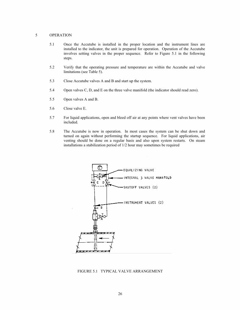
5.1 Once the Accutube is installed in the proper location and the instrument lines areinstalled to the indicator, the unit is prepared for operation. Operation of the Accutubeinvolves setting valves in the proper sequence. Refer to Figure 5.1 in the followingsteps.
5.2 Verify that the operating pressure and temperature are within the Accutube and valve
limitations (see Table 5). 5.3 Close Accutube valves A and B and start up the system. 5.4 Open valves C, D, and E on the three valve manifold (the indicator should read zero). 5.5 Open valves A and B. 5.6 Close valve E. 5.7 For liquid applications, open and bleed off air at any points where vent valves have been
included. 5.8 The Accutube is now in operation. In most cases the system can be shut down and
turned on again without performing the startup sequence. For liquid applications, airventing should be done on a regular basis and also upon system restarts. On steaminstallations a stabilization period of 1/2 hour may sometimes be required
FIGURE 5.1 TYPICAL VALVE ARRANGEMENT
27
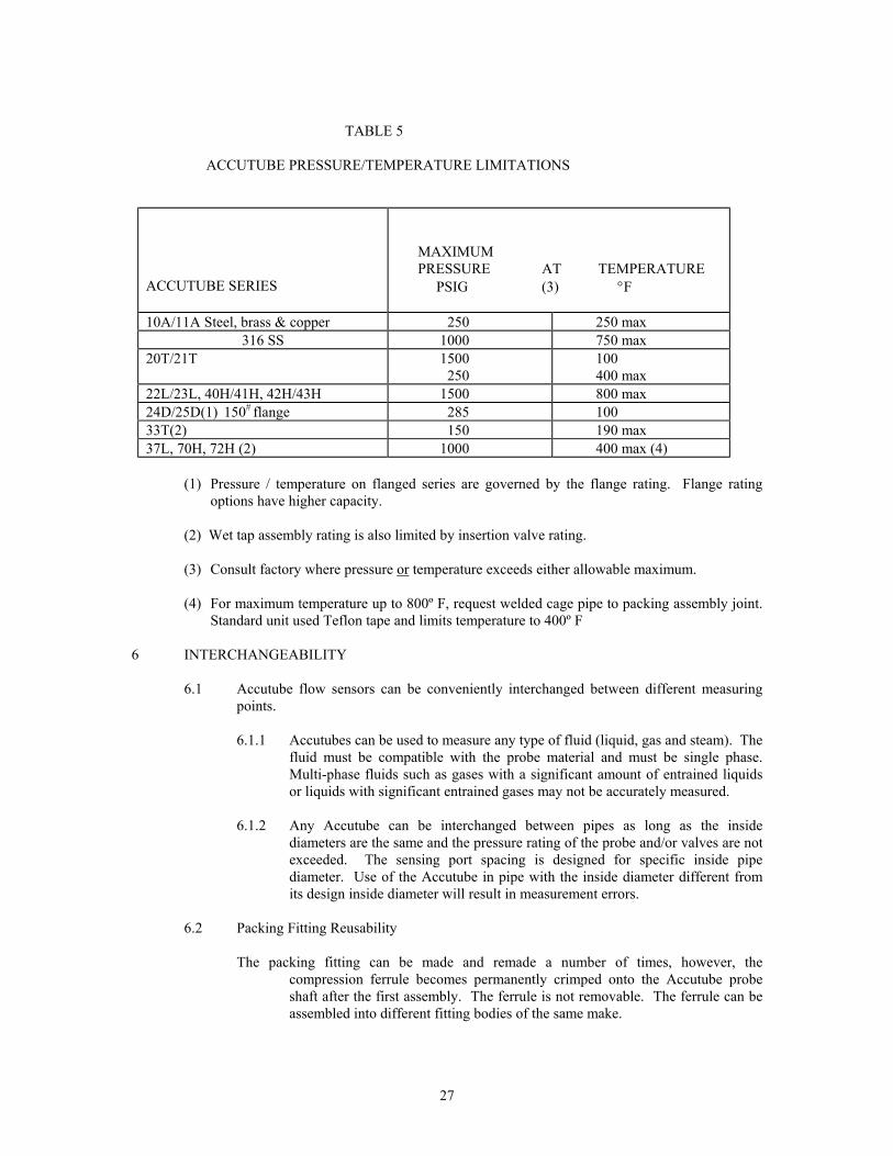
TABLE 5
ACCUTUBE PRESSURE/TEMPERATURE LIMITATIONS
ACCUTUBE SERIES
MAXIMUM PRESSURE AT TEMPERATURE PSIG (3) °F
10A/11A Steel, brass & copper 250 250 max316 SS 1000 750 max
20T/21T 1500250
100400 max
22L/23L, 40H/41H, 42H/43H 1500 800 max24D/25D(1) 150# flange 285 10033T(2) 150 190 max37L, 70H, 72H (2) 1000 400 max (4)
(1) Pressure / temperature on flanged series are governed by the flange rating. Flange ratingoptions have higher capacity.
(2) Wet tap assembly rating is also limited by insertion valve rating.
(3) Consult factory where pressure or temperature exceeds either allowable maximum.
(4) For maximum temperature up to 800º F, request welded cage pipe to packing assembly joint.Standard unit used Teflon tape and limits temperature to 400º F
6 INTERCHANGEABILITY
6.1 Accutube flow sensors can be conveniently interchanged between different measuringpoints.
6.1.1 Accutubes can be used to measure any type of fluid (liquid, gas and steam). The
fluid must be compatible with the probe material and must be single phase.Multi-phase fluids such as gases with a significant amount of entrained liquidsor liquids with significant entrained gases may not be accurately measured.
6.1.2 Any Accutube can be interchanged between pipes as long as the inside
diameters are the same and the pressure rating of the probe and/or valves are notexceeded. The sensing port spacing is designed for specific inside pipediameter. Use of the Accutube in pipe with the inside diameter different fromits design inside diameter will result in measurement errors.
6.2 Packing Fitting Reusability
The packing fitting can be made and remade a number of times, however, the
compression ferrule becomes permanently crimped onto the Accutube probeshaft after the first assembly. The ferrule is not removable. The ferrule can beassembled into different fitting bodies of the same make.

28
7 MAINTENANCE AND REPLACEMENT PARTS
7.1 Cleaning
Accutube performance is generally not sensitive to dirt and film buildup. However, if contamination can build up to the point where internal or port hole blockage is threatened, then precautions must be taken to prevent this. One method commonly used is occasional probe removal for thorough cleaning. Purging systems are also used which on regular intervals inject air or fluid through the probe into the pipe line system, thus flushing out the probe interior. A pressure source and a system of control valves are required to do this.
7.2 Replacement Parts
Accutube probes are completely welded sealed units for greatest integrity and reliability. No parts within the probe are replaceable. Mounting hardware and accessory parts can be obtained from the factory as replacement parts.
8 TROUBLESHOOTING
8.1 Should measurement problems occur with an Accutube probe, the following is a checklist of possible causes:
8.1.1 Probe Position: Verify orientation of probe as stated in Section 1.0. 8.1.2 Upstream/Downstream Piping: Verify proper straight pipe run is as
recommended in Section 1.0. (Table 1) 8.1.3 Pipe I.D.: Verify the inside diameter is nominally the same as that for which the
probe is designed (standard product is Schedule 40 on 20” line size and less, andStandard Weight for larger line size).
8.1.4 Flow Magnitude and Direction: Verify that the reference source for expected
flow is accurate. 8.1.5 Indicator Calibration: Verify indicator accuracy. 8.1.6 Indicator Scale: In installations where the scale is calibrated in flow units for
specific flowing conditions, verify operating conditions agree with scale designconditions. Correction factors may be necessary (see File No. 957:081).
8.1.7 Air Entrapment: In liquid and steam applications, air trapped in high pockets of
instrument piping can cause erratic/erroneous signals. 8.1.8 Blockage: Internal blockage will give an incorrect or no flow indication.

29
9 FLOW CALCULATIONS Flow Equations* 1. Any Liquid Q(GPM) = 5.668 x K x Di
2 x ∆ P/Sf
2. Steam or Any Gas** Q(lb/Hr) = 359.1 x K x Di
2 x ρ x ∆P
3. Any Gas P x ∆ P Q(SCFM) = 128.8 x K x Di
2 x (T + 460) x Ss
Differential Pressure Equations* 1. Any Liquid Q2 x Sf
∆P (In. WC) = K2 x Di4 x 32.14
2. Steam or Any Gas** Q2
∆P (In. WC) = K2 x Di4 x ρ x 128,900
3. Any Gas Q2 x Ss x (T + 460) ∆P (In. WC) = K2 x Di
4 x P x 16,590
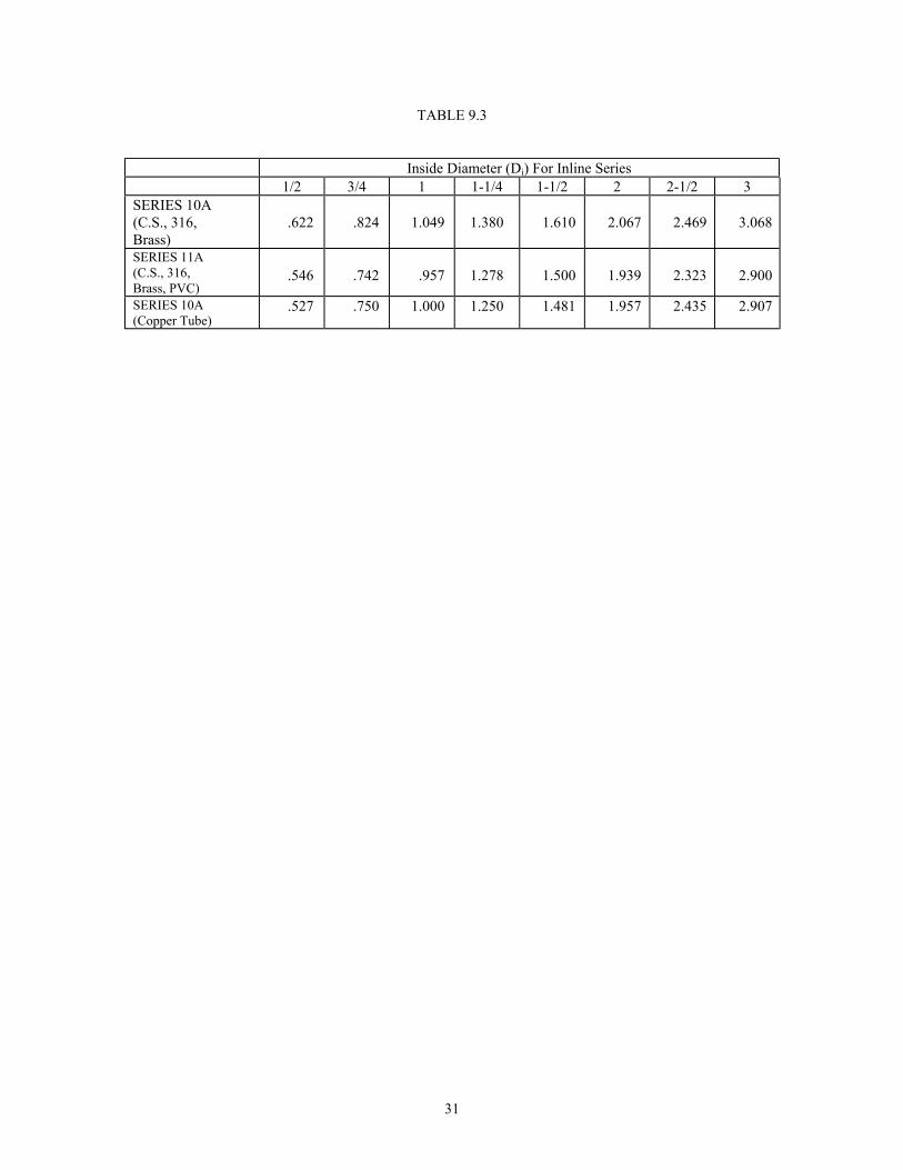
Technical NotationsThe following notations apply:∆ P = Differential pressure expressed in inches of water column Q = Flow expressed in GPM, SCFM of PPH as shown in equation K = Flow coefficient - See table 9.1 & 9.2 Di = Inside diameter of line size expressed in inches - For Inline Series see Table 9.3
For square and 4 x Height x Width rectangular ducts use Di = π
P = Static Line pressure (psia)T = Temperature in degrees Fahrenheit (plus 460 = °Rankine)ρ = Density of medium in pounds per cubic footSf = Liquid Sp. Gr. (density of liquid at flowing temperature / density of water at 60°F)Ss = Gas Sp. Gr. (MWgas / MWair)
*Consult Flow Handbook F/N 957:081 For Equation Derivation and for correction factors for precisecalculations.
**Use of Accutubes on steam applications generating less than 10” wc differential pressure at normal flowrate is not recommended. Reducing pipe size at the meter location may resolve this potential problem.

30
ACCUTUBE FLOW COEFFICIENT (K)
1/2” DIAMETERPROBE
(SER. 22L, 23L, 24D,25D & 37L ONLY)
Pipe SizeInches
K
2 0.5572 1/2 0.5983 0.6453 1/2 0.6304 0.6565 0.6566 0.6628 0.673
10 0.682
3/8” DIAMETERPROBE
Pipe SizeInches
K
1 0.5171 1/4 0.5831 0.5802 0.6382 1/2 0.6173 0.6653 1/2 0.6614 0.6725 0.6716 0.7068 0.665
10 0.696
TABLE 9.1
High Pressure Series 22L, 23L, 24D, 25D, 37L,
40H, 41H, 42H, 43H, 70H & 72H
1” DIAMETERPROBE
Pipe SizeInches
K
6 0.6478 0.678
10 0.65712 0.67714 0.66516 0.69118 0.67820 0.70524 0.70830 0.66436 0.66342 0.67248 0.67360 0.685
TABLE 9.2
Low Pressure Series 20T, 21T, 33T & INLINE
3/4” DIAMETERPROBE
Pipe SizeInches
K
6 0.7068 0.686
10 0.67612 0.68314 0.69816 0.68818 0.68920 0.68624 0.78930 0.72036 0.75742 0.697
2 3/8” DIAMETER PROBE(SER. 24D, 25D & 37L ONLY)
Pipe SizeInches
K
14 0.60316 0.61818 0.62820 0.63424 0.64530 0.67136 0.65248 0.733
>60 0.670
INLINE SERIES
Pipe SizeInches
SeriesNo.
K
1/2 10A and11A
0.407
3/4 “ 0.455 1 “ 0.514 1 1/4 “ 0.584 1 1/2 “ 0.601 2 “ 0.657 2 1/2 “ 0.688 3 “ 0.701
31
TABLE 9.3
Inside Diameter (Di) For Inline Series1/2 3/4 1 1-1/4 1-1/2 2 2-1/2 3
SERIES 10A(C.S., 316,Brass)
.622 .824 1.049 1.380 1.610 2.067 2.469 3.068
SERIES 11A(C.S., 316,Brass, PVC)
.546 .742 .957 1.278 1.500 1.939 2.323 2.900
SERIES 10A(Copper Tube)
.527 .750 1.000 1.250 1.481 1.957 2.435 2.907


