20
Installation Instructions And More These instructions are NOT bike specific Select Your Riding Position

Updated September 2007 1 of 20
Installation Instructions And More
These instructions are NOT bike specific
Select Your Riding Position
Updated September 2007 2 of 20
STOP
Be sure you have the
“Bike Specific Installation Sheet”
Located at
www.convertibars.com/fityourbike
If There is no Bike Specific Installation Sheet
On The Website This is NOT a Confirmed Installation And we do NOT guarantee the fitment
If you are a professional Mechanic
And this is your first installation, be sure that you have the “Bike Specific Installation Sheet”
1. You are expected to read & watch the directions 2. Your customer is expecting a 2 hour install for the base kit 3. More than 2 hours for the base kit is considered training. 4. The customer understands that longer lines will add to the time. 5. If the advertised rise is not achieved, the installation has been
done incorrectly, and you must contact ConvertiBARS for support prior to returning kit.
It is imperative that you understand the above items and
discuss the costs and time of the installation with the customer, prior to beginning.
If you have problems, call our 24-7 support line before giving up.
651-789-1002
After installation, Please be sure the rider has a copy of these instructions, it has
important positioning notes the rider needs to know.

Updated September 2007 3 of 20
Base/Universal Kit Components and Terminology
Riser
Handlebar
Switch Box Holes
Washer Reservoir Mount
Cyclops Clamp
Collet Bolt Plate
Ride Number and
Trim Lines
VG-4 Handlebar
Down Angle

Updated September 2007 4 of 20
Warning! The use of ConvertiBARStm could cause
SERIOUS INJURY or DEATH!
ConvertiBARS or its affiliates will NOT be responsible for any misuse or improper use or installation of this product.
This product has not been presented for D.O.T. certification. Always check with your local Department of
Motor Vehicles before modifying any aspect of your motorcycle.
It is your responsibility to ensure the safe installation of the ConvertiBARS kit, and the safe use of a ConvertiBARS
equipped motorcycle. The properly installed ConvertiBARS equipped motorcycle will operate as the
motorcycle manufacture intended, with full range of steering motion, handlebars secure enough for any riding condition, and no pinched, stretched, or binding lines, and no unintended throttle advance. If you are unable to install this kit properly and or use this kit in a safe manner, the kit should not be installed or used, and should be returned to
the manufacture.
It is also your responsibility to notify anyone riding your ConvertiBARS equipped motorcycle, that it is so equipped,
and that the rider is responsible for ensuring that the handlebars are secure enough for any kind of riding and for
ensuring that the motorcycle will operate as the manufacture intended. Furthermore, there should be no
throttle advance, binding of lines, or tight lines of any kind in any steering position. If any of these or other unsafe situations exist, the ConvertiBARS installation was not
performed correctly, the motorcycle is not safe to ride, and the motorcycle should not be ridden until these things have
been remedied.
Before Every Ride: Ensure that the ConvertiBARS are secure enough for any kind of riding condition and ensure that you have full stop to stop turning ability with no lines pinching, stretching, or
causing throttle advance.
Updated September 2007 5 of 20
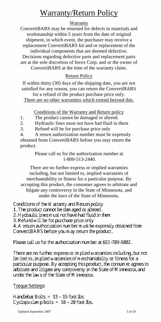
Warranty/Return Policy Warranty
ConvertiBARS may be returned for defects in materials and workmanship within 5 years from the date of original shipment, in which event, the purchaser may receive a
replacement ConvertiBARS kit and or replacement of the individual components that are deemed defective.
Decisions regarding defective parts and replacement parts are at the sole discretion of Invex Corp. and or the owner of
ConvertiBARS at the time of the warranty claim. Return Policy
If within thirty (30) days of the shipping date, you are not satisfied for any reason, you can return the ConvertiBARS
for a refund of the product purchase price only. There are no other warranties which extend beyond this.
Conditions of the Warranty and Return policy
1. The product cannot be damaged or altered. 2. Hydraulic lines must not have had fluid in them 3. Refund will be for purchase price only 4. A return authorization number must be expressly obtained from ConvertiBARS before you may return the product.
Please call us for the authorization number at
1-800-513-2440.
There are no further express or implied warranties including, but not limited to, implied warranties of
merchantability or fitness for a particular purpose. By accepting this product, the consumer agrees to arbitrate and
litigate any controversy in the State of Minnesota, and under the laws of the State of Minnesota.

Updated September 2007 6 of 20
Longer Cable and Hydraulic Lines (In the USA, Contact ConvertiBARS for longer hydraulic
lines, and www.MotionPro.com for longer cable lines) (Outside the USA, you will need to find other suppliers)
Caution ConvertiBARS is not responsible for any lines it does not
make. All warranties and claims are honored by
the respective manufactures. Be sure the lengths and fittings you specify are correct. Lines that are too long or
too short will bind and or stretch, causing an unsafe condition.
Also, most custom lines are not returnable.
How are longer Cable lines made? Scenario 1. The cable company stocks your end fittings. Solution: Have them make new longer lines.
Scenario 2. The cable company does not stock your end fittings. Solution: Send your lines to the cable company; they will make new longer lines reusing the end fittings on the cables.
How are longer Hydraulic lines made? Remaking or adding length to hydraulic lines is not
possible; new longer lines will be needed to be made. How Much Longer Do My Lines Need To Be?
(Follow these steps closely) 1. Remove all cables/lines from the handlebars (keep them
attached to the levers and throttle) 2. Put the handlebars as high as you will ever want them.
(See instructions for positioning) 3. Ensure the routing of the line is ok and there will be no
binding or stretching in any handlebar position 4. Holding the line up, measure how much longer the line will
need to be to reach its mount/handlebar. Tips
Brake lines: 1” longer = 1” added rise Clutch/Throttle Lines: 1” longer = 2” of added rise)
(The above tips are not exact measurements, they are only estimates)
(Your measurements may vary)

Updated September 2007 7 of 20
How To Order Longer Lines?
(You MUST provide the following information to the line companies when ordering custom lines)
(Companies making lines will NOT be able to give you advice on lengths or end fittings)
Cable Lines:
New Line length = Stock + _______ inches (or millimeters) (cable lines always use stock end fittings) Hydraulic Lines:
New Line length = Stock + _______ inches (or millimeters) And New Top Fitting = Stock fitting OR ________ Degree angle bend face down
(As looking through the banjo bolt hole) AND ________ Degree angle bend face to the side
(As looking through the banjo bolt hole)
Important Ensure top fitting has the best bend for clearance when the bars
are as far down and up as they can be.
Recommended Tools-Kit Installation
1. Phillips and Standard Screw drivers 2. Pipe Cutter(for trimming handlebar and riser pipes) 3. Large socket tool for center bearing nut 4. Metric Socket Set 5. Metric Wrench set 6. Offset pliers 7. Bench Vice 8. Metric Allen wrench set 9. Liquid soap(for removing the left grip) 10. Mini-Vac (Vacuum system for bleeding hydraulic lines)

Updated September 2007 8 of 20
Installation Instructions We recommend installing longer lines before beginning.
(Lubricate all cables lines before installing)
Step 2. Remove left grip (Hint: use soap on a screwdriver under the grip)
Step 3. Loosen the brake and clutch levers
On both handlebars
Step 1. Remove left and right bar ends

Updated September 2007 9 of 20
Step 5. If the installation requires installing under the triple clamp, loosen and or remove the two triple clamp
pinch bolts and one main nut. Unbolt reservoir if mounted to handlebar
Step 6. Lift and wiggle to remove triple clamp
Step 4. Loosen 2 screws on each switch box. Hint: You do not need to remove the screws

Updated September 2007 10 of 20
Step 7. Remove handlebars from the forks and from the switch boxes, brake and clutch levers
Step 8. Install the Cyclops clamps as in photo. Mounting the clamp flipped over is optional.

Updated September 2007 11 of 20
Step 9. Only if needed, reroute the lines to maximize their range of travel. Some lines may
not need to be re-routed
Step 10. Reinstall triple clamp and tighten all three

Updated September 2007 12 of 20
Ride Number
VG-4 Handlebar Preparation Step 11
Hint: If the tab on the reservoir mount needs to be bent, assemble the
handlebar and tighten the assembly with the reservoir mount in place,
before bending.
Your Ride Number Is counted from the top down, and also is the
trim number.
See Bike Specific Installation notes for recommended trim
lengths.
1
0
2
3
4
5
6
Attach the reservoir(s) to the reservoir(s) mounts. Use
stock hardware if possible.
After trimming the riser to the desired length. install the riser plug.
Hint: Press plug into the riser by placing it on the floor. Do not hammer it or the plug will
fail.

Updated September 2007 13 of 20
Step 13. Choose a switch box locating hole and Install the left & right switch boxes, brake lever, clutch lever, and throttle controls on the ConvertiBARS handlebars. The
predrilled holes are design to fit most motorcycles, however you may need to drill a new hole if the holes to not
accommodate your motorcycle
Step 12. With the riser separated from the handlebar, insert the ConvertiBARS risers into
the Cyclops clamps

Updated September 2007 14 of 20
IMPORTANT NOTE: When changing the position of ConvertiBARS,
Always use these 4 steps
1.Set handlebar down angle
2.Turn the wheel until it hits the steering stop
3.Position & tighten the Clamp on the fork nearest the tank
4.Position & tighten the Clamp on handlebar nearest the tank
Repeat with the other side
WARNING! You must use either
the washer or reservoir mount. If not the system
could fail
YOU ARE NOW READY TO POSITION THE ConvertiBARS
Step 14. Bolt the handlebar together using the washer or reservoir mount
Step 15. Re-install the Bar-Ends using the stock or kit hardware

Updated September 2007 15 of 20
Positioning ConvertiBARS Changing the down angle of the handlebar
The indexed down angles are 8 ,4 ,0 , -4, -8 degrees
1. Loosen the bolt until the bolt head is clear of the bolt
plate
2. Rotate Lever/Handlebar
3. With a firm grasp, grip & flex the handlebar up and
down until the collet pops out
4. Rotate Lever/Handlebar, collet, and bolt plate together
to a new indexed position
5. Push collet inside riser head
6. Tighten Bolt

Updated September 2007 16 of 20
To set the “Down and foreword” First, set the down angle of the handlebars, then
Turn the wheel to the steering stop Rotate the Cyclops clamps as far foreword as possible and
push the handlebars down as far as possible (Riser pipe should be in front of the forks if possible)
Repeat with other side Once tight, ensure stop to stop turning
Tighten Cyclops clamp on the fork first, Then tighten the Cyclops clamp on handlebar riser.
Use two fingers for spacing/tank clearance. Do all this at the steering stop.

Updated September 2007 17 of 20
Tighten everything down, bleed the hydraulic lines and triple check all the bolts and nuts
To set the “up-aft position” First, set the down angle of the handlebars,
Next turn wheel to the steering stop Rotate the Cyclops clamps as far back as possible
(approx. 7 and 5 O’clock Positions) Lift the handlebars up as far as possible
Repeat with other side Once tight, ensure stop to stop turning
Tighten Cyclops clamp on the fork first, Then tighten the Cyclops clamp on handlebar riser.
Use two fingers for spacing/tank clearance. Do all this at the steering stop.

Updated September 2007 18 of 20
Hints/Tips
Converting TIPS Always keep one side tight while converting the other side.
Use 1, 2, or 3 fingers as a spacer between the tank and handlebar to ensure the same alignment on both sides and to
ensure proper tank clearance.
We do NOT recommend altering the factory Steering stops. Only if absolutely needed, use fairing spacer pack or other lifting
components to lift fairing for more handlebar rise.
Use seams and on the Cyclops clamps and triple clamp for alignment and mark the positions so repeating these locations are
fast and easy

Updated September 2007 19 of 20
6.0” Riser = Trim Number 10 How Long Should Your Riser Be?
Hints and Tips Trimming a handlebar: Before you trim a handlebar, here are some important things to know
A. Always use a pipe cutter, never use a hack saw
B. Round the cut edges so they are not sharp
C. Do not apply heavy pressure when cutting. If you do, you could bend the pipe out of round.
D. Trimming the handlebar pipe: Before you trim the handlebar pipe, be sure that all your controls will fit on the shorter handlebar.
E. Trimming the riser pipe: Do not trim the riser pipe until you are sure of the amount to trim. Trimming the riser piece is only needed for clearance of the intake ducts or fairing side pieces. Be sure you have correctly positioned the clamps to get the most of ConvertiBARS before you trim the riser, also Consult the “Bike Specific Installation Sheets” for
more details on how much of the riser to trim. “Trim Number”
Installing Brake Line Bands and Under-clips (optional) If you install longer hydraulic lines,
do NOT zip tie them. Use the Hydraulic Line bands. The bands hold securely yet allow the lines to
flex with out damage
Install the under clips by pushing the Cyclops clamps up against the underside of the triple
clamp and tighten with offset pliers. To remove, press down on one side. Fairing and Tank Interference When Positioning ConvertiBARS, you always begin at the steering stop and space the handlebars off the tank, so tank clearance should never be an issue. However, the fairing may restrict rise. Note that fairing/windshield contact is ok, as long as you can reach the steering stops with out damaging anything.
How Much Rise? = Trim Number?

Updated September 2007 20 of 20
What’s Your Ride Number?
www.ConvertiBARS.com


