Notice: Andrew disclaims any liability or responsibility for the results of improper or unsafe installation, inspection, maintenance, or removal practices.Aviso: Andrews no acepta ninguna obligacion ni responsabilidad como resultado de practicas incorrectas o peligrosas de instalacion, inspecci6n, mantenimiento o retire.Avis : Andrew decline toute responsabilite pour les consequences de procedures d'installation, d'inspection, d'entretien ou de retrait incorrectes ou dangereuses.Hinweis: Andrew lehnt jede Haftung Oder Verantwortung fur Schaden ab, die aufgrund unsachgemaBer Installation, Uberprufung, Wartung Oder Demontage auftreten.Atencao: A Andrew abdica do direito de toda responsabilidade pelos resultados de praticas inadequadas e sem seguranca de instalacao, inspecao, manutengao ou remocao.Awertenza: Andrew declina eventual! responsabilita denvanti dell'esecuzione di procedure di installazione, ispezione, manutenzione e smontaggio improprie o poco sicure.
BRevREStatusModel Version 04
01Version 01 AStatus Rev
2 of 14pageBulletin AE01B-A0599-001
Installation InstructionsMT050C
Section 1 - General Information
1.1 - Introduction
This manual contains the information needed to install, operate and maintain the MT050C Series DryLine® dehydrator. Please take the time to read this manual before attempting to operate or service the unit.
1.2 - Description
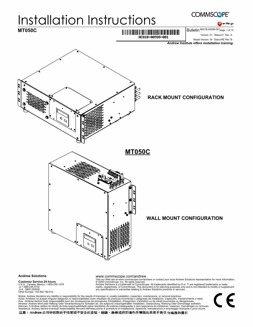
MT050C Series DryLine® dehydrators provide dry air for pressurizing small (up to 60 cubic feet, or 1700 liters, in volume) antenna and transmission line systems. The dehydrators produce -50ºF (-45ºC) dew point dry air at an output rate of 0.12 cubic feet (3.4 liters) per minute.
Each dehydrator consists of an electrically-driven air compressor, a membrane dryer assembly, an automatic transmission line pressure sensing system and alarm outputs housed in a rigid metal chassis. It is designed to mount in a standard 19” equipment rack, wall, or on a shelf. The front panel features a control interface with display for alarms and pressure. For easy serviceability, power connections, alarm output connections and all filter elements are accessible from the rear or front of the unit. The MT050C maintains transmission line pressures at 3.0 psig (20.7 kPa). It is intended for standard microwave antenna applications and any other transmission line pressurization requirement that supports a medium pressure limit.
1.3 - Operation
The MT050C DryLine® dehydrator, while similar in moisture removal technology, operates differently than some of the DryLine® series of dehydrators. In order to provide a constant supply of dry air to small air volume systems, and to maintain an acceptable dryness level in the product air stream, a high-pressure reservoir tank is utilized. This reservoir tank is connected to a pressure regulator and orifice to yield a fixed output pressure of 3.0 psig and a nominal flow rate of 0.12 SCFM. In addition to supplying the output air, the reservoir tank also provides the dry air for the feedback loop. The feedback loop is necessary to maintain the dryness of the membrane cartridge.
During normal operation, the feedback loop will cause the pressure to slowly drop in the internal reservoir tank, and the MT050C compressor will cycle automatically. These cycles will take place regardless of the system volume or condition of the transmission line the dehydrator is connected to. The rate of these cycles, however, may varyslightly.
When connected to a very tight system, or the output is capped, the dehydrator will cycle approximately every 60 minutes and maintain 3.0 psig system pressure. When open to atmosphere, the dehydrator will cycle approximately every 3 minutes while providing close to 0.12 SCFM of dry air. A system that leaks will have a cycle time somewhere in between, depending on the severity of the leaks.
The display will also reflect a pressure between 0 and 3.0 psig while the output flow is between 0 and 0.12 SCFM. The pressure sensor tracks the pressure beyond the flow control orifice and will show the actual pressure in the transmission lines (or to the distribution manifold).
NOTICE: The installation, maintenance or removal of pressurization equipment requires qualifiedand experienced personnel. Pressurization systems should be inspected once per year by qualified technicians to verify proper installation, maintenance and condition of equipment. Commscope disclaims any liability or responsibility for the result of improper or unsafe installationpractices.
BRevREStatusModel Version 04
01Version 01 AStatus Rev
3 of 14pageBulletinAE01B-A0599-001
Installation InstructionsMT050C
During the initial pressurization of the transmission line, the dehydrator will cycle every 2 to 4 minutes with the system at 0 psig pressure. The cycle time of the dehydrator will become stable once the transmission system is fully pressurized.
1.4 - Alarms
The MT050C offers Low Pressure, High Humidity (Optional Kit), Excess Run and Power Fail alarms as a standard feature. In addition, a summary alarm connection is provided on all units. Alarm conditions are indicated on the display. The alarms are dry contacts and are set for continuity on alarm.
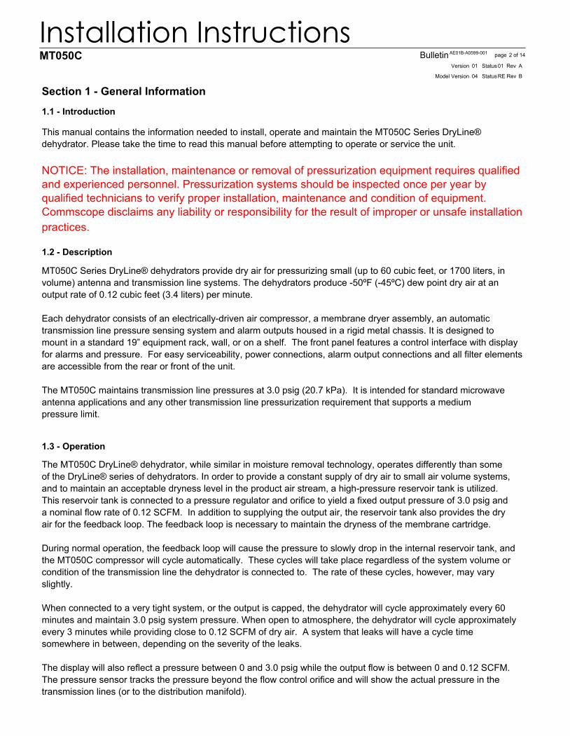
The external alarm monitoring system (supplied by others) is connected to the terminal strip located on top of the cabinet. A small slotted screwdriver is necessary to make the connections.
The connections to the alarm strip are as follows; refer to Figure 1 and 2 for correct locations and colors of the wires on the terminal strip.
Summary: Activates when the High Humidity, Excess Run, and/or Low Pressure alarms are triggered. The summary alarm does not report Power Fail.
Power Fail: Activates when power is removed from the dehydrator. This includes turning the power off at the switch.
High Humidity: Activates when system or dehydrator output humidity rise above 7.5% relative humidity. At initial installation, this alarm will continue to alarm until the system has been properly purged. This alarm is optional and can be purchased separately as MT/HR-KIT-HUMIDITY.
1 32
NOTE: HIGH HUMIDITY ALARM IS NOT INCLUDED AS A STANDARD FEATURE. IT IS SOLD SEPARATELY AS MT/HR-KIT-HUMIDITY*
121
BRevREStatusModel Version 04
01Version 01 AStatus Rev
4 of 14pageBulletinAE01B-A0599-001
Installation InstructionsMT050C
Excess Run: Factory strapped run time set in accordance with the normal run time for the dehydrator application. Selectable times are 1, 10, 30, 120 and 240 minutes, with the 10 minute selection used on the MT050C as the default setting.
Low Pressure: If system pressure falls below the low-pressure trigger point (1.0 psig on the MT050C), the low-pressure alarm sensor will activate an alarm contact. This alarm is an indication of a significant system leak or a dehydrator failure.
Note: All of the alarms clear and reset automatically, but can be manually reset in the display menus. However, if the alarm condition still exists, the alarm will return immediately after being reset.
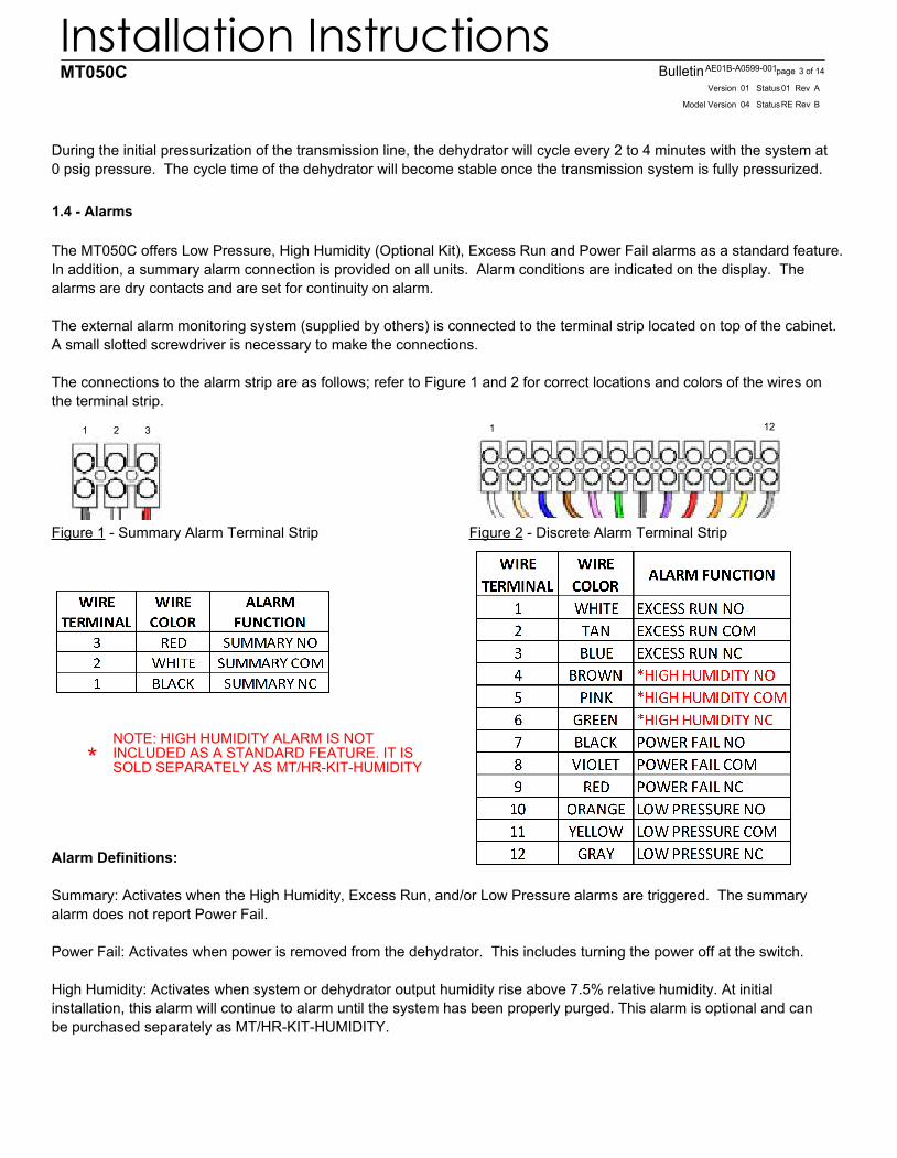
1.5 - Specifications
BRevREStatusModel Version 04
01Version 01 AStatus Rev
5 of 14pageBulletinAE01B-A0599-001
Installation InstructionsMT050C
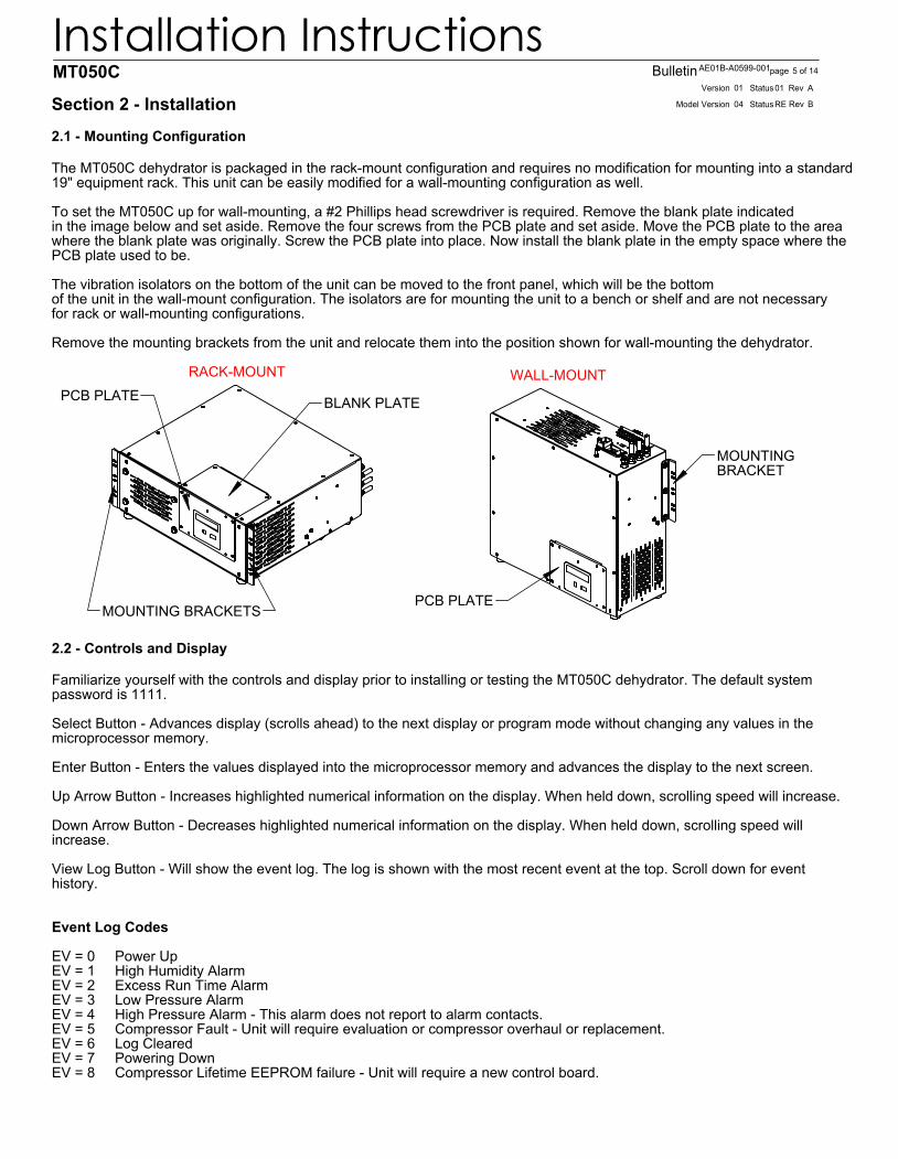
BLANK PLATEPCB PLATE
RACK-MOUNT
MOUNTING BRACKETS
WALL-MOUNT
PCB PLATE
MOUNTINGBRACKET
2.1 - Mounting Configuration
Section 2 - Installation
The MT050C dehydrator is packaged in the rack-mount configuration and requires no modification for mounting into a standard19" equipment rack. This unit can be easily modified for a wall-mounting configuration as well.
To set the MT050C up for wall-mounting, a #2 Phillips head screwdriver is required. Remove the blank plate indicated in the image below and set aside. Remove the four screws from the PCB plate and set aside. Move the PCB plate to the areawhere the blank plate was originally. Screw the PCB plate into place. Now install the blank plate in the empty space where the PCB plate used to be.
The vibration isolators on the bottom of the unit can be moved to the front panel, which will be the bottomof the unit in the wall-mount configuration. The isolators are for mounting the unit to a bench or shelf and are not necessaryfor rack or wall-mounting configurations.
Remove the mounting brackets from the unit and relocate them into the position shown for wall-mounting the dehydrator.
2.2 - Controls and Display
Familiarize yourself with the controls and display prior to installing or testing the MT050C dehydrator. The default system password is 1111.
Select Button - Advances display (scrolls ahead) to the next display or program mode without changing any values in themicroprocessor memory.
Enter Button - Enters the values displayed into the microprocessor memory and advances the display to the next screen.
Up Arrow Button - Increases highlighted numerical information on the display. When held down, scrolling speed will increase.
Down Arrow Button - Decreases highlighted numerical information on the display. When held down, scrolling speed will increase.
View Log Button - Will show the event log. The log is shown with the most recent event at the top. Scroll down for event history.
Event Log Codes
EV = 0 Power UpEV = 1 High Humidity AlarmEV = 2 Excess Run Time AlarmEV = 3 Low Pressure AlarmEV = 4 High Pressure Alarm - This alarm does not report to alarm contacts.EV = 5 Compressor Fault - Unit will require evaluation or compressor overhaul or replacement.EV = 6 Log ClearedEV = 7 Powering DownEV = 8 Compressor Lifetime EEPROM failure - Unit will require a new control board.
BRevREStatusModel Version 04
01Version 01 AStatus Rev
6 of 14pageBulletinAE01B-A0599-001
Installation InstructionsMT050C
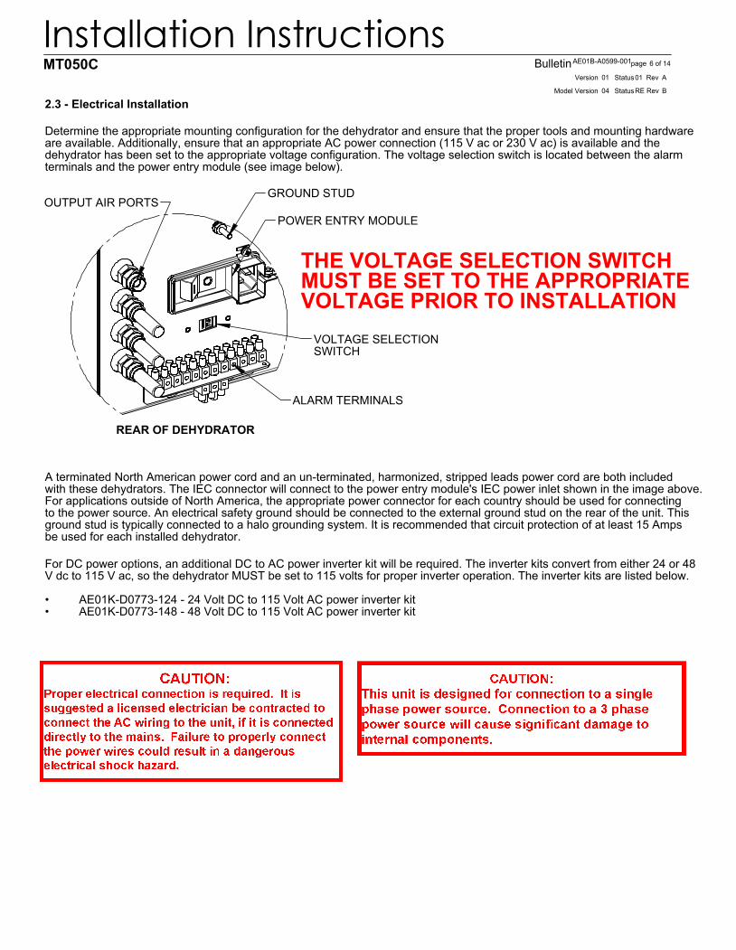
ALARM TERMINALS
POWER ENTRY MODULE
GROUND STUDOUTPUT AIR PORTS
REAR OF DEHYDRATOR
VOLTAGE SELECTION SWITCH
2.3 - Electrical Installation
Determine the appropriate mounting configuration for the dehydrator and ensure that the proper tools and mounting hardwareare available. Additionally, ensure that an appropriate AC power connection (115 V ac or 230 V ac) is available and the dehydrator has been set to the appropriate voltage configuration. The voltage selection switch is located between the alarmterminals and the power entry module (see image below).
THE VOLTAGE SELECTION SWITCH MUST BE SET TO THE APPROPRIATEVOLTAGE PRIOR TO INSTALLATION
A terminated North American power cord and an un-terminated, harmonized, stripped leads power cord are both includedwith these dehydrators. The IEC connector will connect to the power entry module's IEC power inlet shown in the image above.For applications outside of North America, the appropriate power connector for each country should be used for connectingto the power source. An electrical safety ground should be connected to the external ground stud on the rear of the unit. Thisground stud is typically connected to a halo grounding system. It is recommended that circuit protection of at least 15 Ampsbe used for each installed dehydrator.
For DC power options, an additional DC to AC power inverter kit will be required. The inverter kits convert from either 24 or 48V dc to 115 V ac, so the dehydrator MUST be set to 115 volts for proper inverter operation. The inverter kits are listed below.
AE01K-D0773-124 - 24 Volt DC to 115 Volt AC power inverter kit•AE01K-D0773-148 - 48 Volt DC to 115 Volt AC power inverter kit•
BRevREStatusModel Version 04
01Version 01 AStatus Rev
7 of 14pageBulletinAE01B-A0599-001
Installation InstructionsMT050C
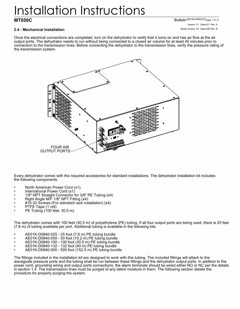
FOUR AIR OUTPUT PORTS
2.4 - Mechanical Installation
Once the electrical connections are completed, turn on the dehydrator to verify that it turns on and has air flow at the air output ports. The dehydrator needs to run without being connected to a closed air volume for at least 45 minutes prior to connection to the transmission lines. Before connecting the dehydrator to the transmission lines, verify the pressure rating of the transmission system.
Every dehydrator comes with the required accessories for standard installations. The dehydrator installation kit includes the following components.
North American Power Cord (x1)•International Power Cord (x1)•1/8" NPT Straight Connector for 3/8" PE Tubing (x4)•Right Angle M/F 1/8" NPT Fitting (x4)•#10-32 Screws (For standard rack installation) (x4)•PTFE Tape (1 roll)•PE Tubing (100 feet, 30.5 m)•
The dehydrator comes with 100 feet (30.5 m) of polyethylene (PE) tubing. If all four output ports are being used, there is 25 feet(7.6 m) of tubing available per port. Additional tubing is available in the following kits.
AE01K-D0840-025 - 25 foot (7.6 m) PE tubing bundle•AE01K-D0840-050 - 50 foot (15.2 m) PE tubing bundle•AE01K-D0840-100 - 100 foot (30.5 m) PE tubing bundle•AE01K-D0840-132 - 132 foot (40 m) PE tubing bundle•AE01K-D0840-500 - 500 foot (152.5 m) PE tubing bundle•
The fittings included in the installation kit are designed to work with this tubing. The included fittings will attach to the waveguide pressure ports and the tubing shall be run between these fittings and the dehydrator output ports. In addition to thepower cord, grounding wiring and output ports connections, the alarm terminals should be wired either NO or NC per the detailsin section 1.4. The transmission lines must be purged of any latent moisture in them. The following section details the procedure for properly purging the system.
BRevREStatusModel Version 04
01Version 01 AStatus Rev
8 of 14pageBulletinAE01B-A0599-001
Installation InstructionsMT050C
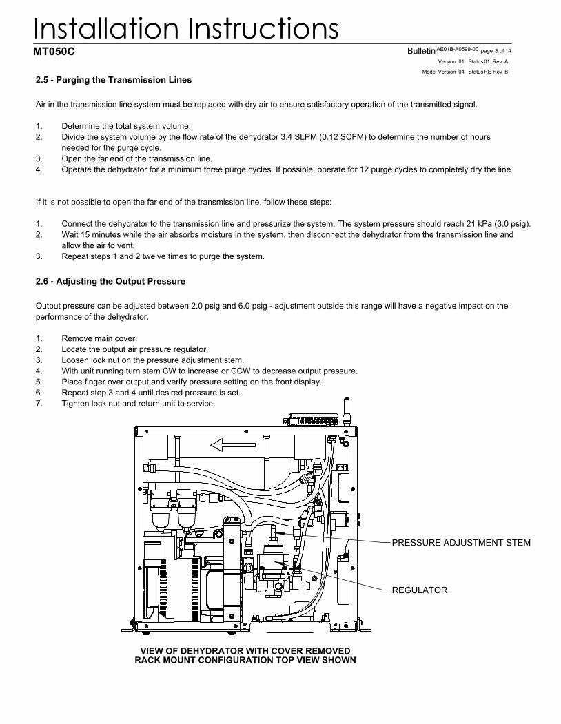
VIEW OF DEHYDRATOR WITH COVER REMOVEDRACK MOUNT CONFIGURATION TOP VIEW SHOWN
REGULATOR
PRESSURE ADJUSTMENT STEM
2.5 - Purging the Transmission Lines
Air in the transmission line system must be replaced with dry air to ensure satisfactory operation of the transmitted signal.
Determine the total system volume. 1.Divide the system volume by the flow rate of the dehydrator 3.4 SLPM (0.12 SCFM) to determine the number of hours 2.needed for the purge cycle. Open the far end of the transmission line. 3.Operate the dehydrator for a minimum three purge cycles. If possible, operate for 12 purge cycles to completely dry the line. 4.
If it is not possible to open the far end of the transmission line, follow these steps:
Connect the dehydrator to the transmission line and pressurize the system. The system pressure should reach 21 kPa (3.0 psig). 1.Wait 15 minutes while the air absorbs moisture in the system, then disconnect the dehydrator from the transmission line and 2.allow the air to vent. Repeat steps 1 and 2 twelve times to purge the system. 3.
2.6 - Adjusting the Output Pressure
Output pressure can be adjusted between 2.0 psig and 6.0 psig - adjustment outside this range will have a negative impact on the performance of the dehydrator.
Remove main cover.1.Locate the output air pressure regulator. 2.Loosen lock nut on the pressure adjustment stem.3.With unit running turn stem CW to increase or CCW to decrease output pressure. 4.Place finger over output and verify pressure setting on the front display. 5.Repeat step 3 and 4 until desired pressure is set. 6.Tighten lock nut and return unit to service. 7.
BRevREStatusModel Version 04
01Version 01 AStatus Rev
9 of 14pageBulletinAE01B-A0599-001
Installation InstructionsMT050C
3.0 - Maintenance
Section 3 - Maintenance
The MT050C Dehydrator requires relatively little maintenance to ensure satisfactory operation over long periods of time. This section outlines the recommended annual preventive maintenance for the unit and the suggested overhaul for every 6000 hours of compressor operation.
3.1 - Regular Maintenance
The MT050B Dehydrator will perform at an optimum if it is routinely checked for correct performance. This checking generally consists of an annual inspection of the condition of the air intake filter and an overhaul after every 6000 hours of compressor operation. Performance of these measures is sufficient to ensure continued reliable operation.
3.2 - Preventive Maintenance
The annual maintenance of a MT050C consists of a preventive maintenance inspection of the dehydrator and replacement of the foam air intake filter. This task can easily be performed in the field with the unit connected to the transmission line system and with only the main cover removed for maintenance.
3.3 - Filter Element Replacement
Periodically, the air intake filter on the compressor will require replacement. The air intake filter protects the compressor from contamination and dust. Periodic replacement extends the life of the compressor. To gain access to the element, push in on the cover and rotate the housing approximately 1/4 turn CCW. The filter is made of a fibrous material and should be replaced once a year (or more frequently, if the operating environment is very dusty). Remove the old filter and discard. Ensure the new filter is seated completely in the housing and then replace the cover.
When the unit is inspected, the coalescing filter elements should be checked. If they appear discolored or have material buildup, they should be replaced.
3.4 - Annual Inspection
Inspection includes checking for loose or damaged hoses, fittings and electrical connections. Remove the cover and verify that there is not excessive water build-up in the two filter bowls. There may be some droplets of water in the filter bowls (the lower portion of each bowl), but there should be only a small amount of liquid in either bowl. If there is excessive water, refer to the troubleshooting section 4. Replacement of the filter elements in the coalescing filters are covered in the overhaul section of their respective replacement kits.
3.4.1 Check the electrical connections.
Check the screw at the power input connector to ensure that the ac power cord is securely terminated. Check the screw-in alarm terminals to ensure that all wire connections are tight. A loose or damaged connection may result in erratic operation and unnecessary downtime. Refer to the troubleshooting section if an electrical problem is encountered.
3.4.2 Check the ground wire.
Check that an electrical safety ground is installed on the stud on the rear of the dehydrator. This connection point is adjacent to the power input connector. (It is intended to be customer installed in the field to the customer halo system).
3.4.3 Check the hour meter
Check the hour meter in the display to help to determine the duty cycle of the dehydrator. If the dehydrator has been running for more than 20% of its installed time, check the systems for leaks. Also check the time on the meter to determine if it is time to perform the 6000-hour overhaul.
BRevREStatusModel Version 04
01Version 01 AStatus Rev
10 of 14pageBulletinAE01B-A0599-001
Installation InstructionsMT050C
3.5 Parts Replacement and Dehydrator Overhaul
COMMSCOPE MT050C dehydrators are designed to give many years of trouble-free service and require very minimal maintenance. The dehydrator contains, as a standard feature, an electronic hour meter that records compressor run hours. To ensure continuous and reliable operation, the dehydrator must be overhauled every 6000 hours of compressor operation. The overhaul kit, listed below, contains all of the necessary parts to perform this overhaul. The dehydrator overhaul kit includes parts to overhaul the compressor and critical components in the dehydrator that often become worn over time.
3.5.1 In Case Of Difficulty:
If the dehydrator is not operating, refer to Section 2 on Installation and Section 4 on Troubleshooting the unit.
3.5.2 Tools
The following tools are used in the maintenance and overhaul procedures. • Adjustable open-end wrench • Allen wrench 5/32 • #2 Phillips screwdriver • Small flat-blade screw-driver
3.5.3 Overhaul Procedure
When the MT050C compressor run time reaches 6000 hours (or a multiple of 6000 hours) it is time to replace certain items in the compressor and the air path of the dehydrator. These include the piston cups, piston seals and head gaskets of the compressor, the filter elements in the water and coalescing filters, and the tube section connecting the compressor output to the coalescing filter input.
3.5.4 Unit Shutdown and Removal
In order to perform an overhaul on the MT050C, the unit must be turned off, power removed and removed from service. As this is being done, the low pressure alarm may active through a reporting alarm system. Personnel monitoring such an alarm should be notified in advance so that they are aware of the fact that service is being performed. It is also necessary to disconnect the dehydrator dry air output from the waveguide system during the overhaul.
3.5.5 Remove the compressor for overhaul
To remove the compressor, open the cover panel of the unit.
Disconnect the compressor wiring (6-pin connector) from control board. 1.Disconnect the tubing from the output of the compressor. The tubing and hose clamp can be discarded as replacements are 2.provided in the compressor overhaul kit.Remove the four compressor screws from the bottom and front of the dehydrator. Remove the compressor from the chassis.3.Remove the brackets that cover the compressor head.Follow the instructions included in the compressor overhaul kit. When the overhaul is complete, reinstall in reverse order. 4.
3.6 Service Restoration
RECOMMENDATION: If the dehydrator overhaul process has taken more than a few hours, it is recommended that the unit be run for one hour without beingconnected to any closed air volume in order to purge the membrane dryer and tank of any accumulated moisture. If the transmission lineshave been exposed to ambient air and/or have not retained their system pressure, it is also recommended that the lines be purged.
BRevREStatusModel Version 04
01Version 01 AStatus Rev
11 of 14pageBulletinAE01B-A0599-001
Installation InstructionsMT050C
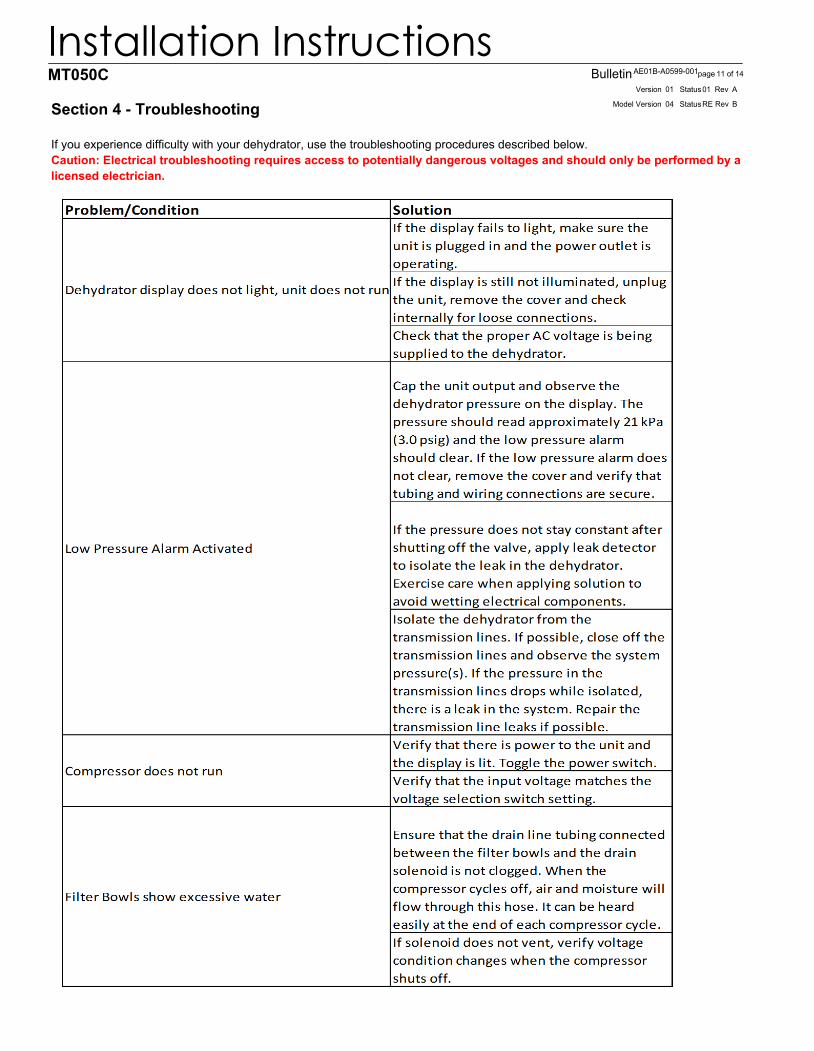
Section 4 - Troubleshooting
If you experience difficulty with your dehydrator, use the troubleshooting procedures described below. Caution: Electrical troubleshooting requires access to potentially dangerous voltages and should only be performed by a licensed electrician.
BRevREStatusModel Version 04
01Version 01 AStatus Rev
12 of 14pageBulletinAE01B-A0599-001
Installation InstructionsMT050C
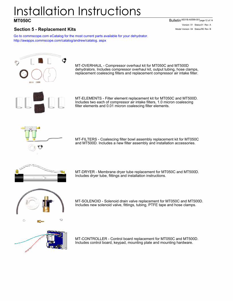
Section 5 - Replacement KitsGo to commscope.com eCatalog for the most current parts available for your dehydrator.http://awapps.commscope.com/catalog/andrew/catalog. aspx
MT-OVERHAUL - Compressor overhaul kit for MT050C and MT500Ddehydrators. Includes compressor overhaul kit, output tubing, hose clamps,replacement coalescing filters and replacement compressor air intake filter.
MT-ELEMENTS - Filter element replacement kit for MT050C and MT500D.Includes two each of compressor air intake filters, 1.0 micron coalescingfilter elements and 0.01 micron coalescing filter elements.
MT-FILTERS - Coalescing filter bowl assembly replacement kit for MT050Cand MT500D. Includes a new filter assembly and installation accessories.
MT-SOLENOID - Solenoid drain valve replacement for MT050C and MT500D.Includes new solenoid valve, fittings, tubing, PTFE tape and hose clamps.
MT-DRYER - Membrane dryer tube replacement for MT050C and MT500D.Includes dryer tube, fittings and installation instructions.
MT-CONTROLLER - Control board replacement for MT050C and MT500D. Includes control board, keypad, mounting plate and mounting hardware.
COMMSCOPE provides in-warranty and out-of-warranty repairs as well as dehydrator and compressor overhauls from several Repair Centers. Coordination of these services is provided through the nearest Sales Office or Customer Service Center. The RepairCenter is also prepared to help you with the following:
Technical Assistance •Troubleshooting •Repairs •Loaner Units (if available)•Spare Parts •Installation Materials •System Accessories •
6.1 - In Case of Trouble
The first step you should take if trouble develops using a dehydrator is to read the operators manual and follow the trouble isolating procedures given in it. If the steps in the manual do not identify and remedy the problem, then contact a COMMSCOPE Customer Service Center for 24- hour telephone assistance. Record the Model Number (e.g. MT050B) and Serial Number from the product label, as you will be asked for these when you call. Two main locations are currently available to help:
From NorthAmerica Telephone: 1-800-255-1479 Fax (U.S.A.): 1-800-349-5444
International Telephone: +1-779-435-6500 Fax Number: +1-779-435-8579
When your call, fax or email communication is received, the COMMSCOPE staff will work with you to pinpoint the possible cause of trouble. If the pressurization equipment is suspect, they will:
ask for your unit Model Number and Serial Number •check the warranty status of the unit •advise the availability of a loaner unit •if the unit is out-of-warranty, provide an estimate of the cost for inspection and repairs •fax a Return Material Authorization sheet to you•
BRevREStatusModel Version 04
01Version 01 AStatus Rev
14 of 14pageBulletinAE01B-A0599-001
Installation InstructionsMT050C
6.3 Repair Center Process
A method of Payment must be provided prior to issuing of Return Material Authorization (RMA) regardless of warranty status.
IN-WARRANTY REPAIR: Most COMMSCOPE pressurization products carry a warranty of one to three years, depending upon model number. Warranty details are available on our web page. If your unit falls within its warranty period, inspection and repairs will be performed at no charge and the unit will be promptly returned to you. If a warranty unit is deemed no problem found an inspection fee and freight will be charged to the customer.
OUT-OF-WARRANTY REPAIR: We will inform you with the cost of repair and obtain your approval to proceed with repairs or, if you elect not to have the unit repaired, your instructions on disposition of your unit. When repairs are complete, we will return your unit and invoice you for the inspection charge, materials used for the repair and labor applied to complete the repair. If you elected not to repair the unit, we will invoice you for the inspection plus freight charges if unit is to be returned.
LOANER UNITS: Loaner units may be available from the repair center to maintain your system while repairs are being performed. If you feel you need a loaner, please contact us at one of the numbers listed under contact numbers. A purchase order(P.O.) for the full value of the unit must be issued prior to shipment. Also contact us when the loaner is ready to be returned so that we can issue a NEW RMA to identify your return and create the appropriate credit to your account. Damages to loaner will be deducted from the P.O.
PACKING INSTRUCTIONS: Pack your unit securely for shipment to the Repair Center. If you received a loaner unit, we suggest you use the box and packing materials to return your unit. Otherwise we have factory packing materials available for a nominal fee. Enclose a completed copy of this form inside the box and clearly mark your Company Name and RMA: XXXXXXX on outside of the box. Address the box to the following ship-to address:
COMMSCOPE PRESSURIZATION SERVICE CENTER RMA# XXXXXXX 11312 S. PIPELINE RD. EULESS, TX. 76040-6629
Please note, units received with biological/animal contamination will be returned unrepaired or scrapped after notification and you will be invoiced for inspection and freight.
CONTACT NUMBERS: If you have any questions about the repair process or status of your unit, please contact us directly through one of the following methods: