HRVCCLHA HRVCCSVU HRVCCLVU Heat Recovery Ventilator Installation Instructions A05260 HRVCCLHA -- Conventional Unit A92268 HRVCCSVU -- Compact Unit A92377 HRVCCLVU -- High Efficiency Unit NOTE: Read the entire instruction manual before starting the installation. SAFETY CONSIDERATIONS Improper installation, adjustment, alteration, service, maintenance, or use can cause explosion, fire, electrical shock, or other conditions which may cause death, personal injury or property damage. Consult a qualified installer, service agency or your distributor or branch for information or assistance. The qualified installer or agency must use factory--authorized kits or accessories when modifying this product. Refer to the individual instructions packaged with the kits or accessories when installing. Follow all safety codes. Wear safety glasses, protective clothing, and work gloves. Have a fire extinguisher available. Read these instructions thoroughly and follow all warnings and cautions included in literature and attached to the unit. Consult local building codes and the current edition of the National Electrical Code (NEC) NFPA 70. In Canada, refer to the current editions of the Canadian Electrical Code CSA C22.1. Recognize safety information. When you see this symbol on the unit and in instructions or manuals, be alert to the potential for personal injury. Understand the signal words DANGER, WARNING, and CAUTION. These words are used with the safety--alert symbol. DANGER identifies the most serious hazards, which will result in severe personal injury or death. WARNING signifies hazards, which could result in personal injury or death. CAUTION is used to identify unsafe practices, which may result in minor personal injury or product and property damage. NOTE is used to highlight suggestions which will result in enhanced installation, reliability, or operation. INTRODUCTION The Heat Recovery Ventilator (HRV) is used to exchange indoor stale air with outside fresh air. The HRV unit is equipped with a special heat recovery core which transfers sensible heat between the fresh incoming air and stale exhaust air. It is required to locate the HRV in a conditioned space. Special attention should be given to condensate drain, duct application, balancing the HRV, and locating unit for easy access and routine maintenance. The cross--flow design core allows entering and leaving air streams to transfer heat energy without mixing. LOCATION Inspect Equipment Move carton to final installation location. Remove the HRV from carton taking care not to damage unit. Remove all packaging and inspect unit for damage. Remove parts bag from inside unit. File claim with shipping company if shipment is damaged or incomplete.
Transcript
HRVCCLHAHRVCCSVUHRVCCLVUHeat Recovery Ventilator
Installation Instructions
A05260
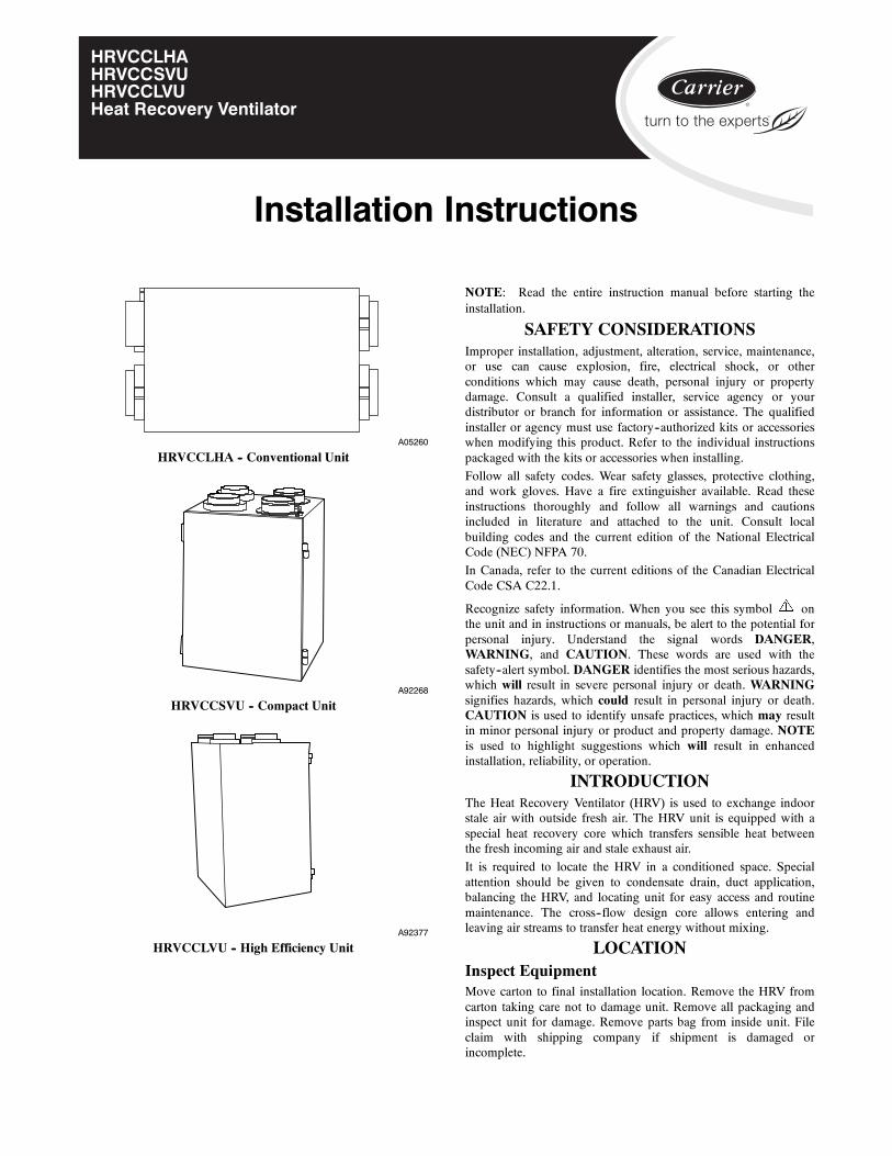
HRVCCLHA -- Conventional Unit
A92268
HRVCCSVU -- Compact Unit
A92377
HRVCCLVU -- High Efficiency Unit
NOTE: Read the entire instruction manual before starting theinstallation.
SAFETY CONSIDERATIONSImproper installation, adjustment, alteration, service, maintenance,or use can cause explosion, fire, electrical shock, or otherconditions which may cause death, personal injury or propertydamage. Consult a qualified installer, service agency or yourdistributor or branch for information or assistance. The qualifiedinstaller or agency must use factory--authorized kits or accessorieswhen modifying this product. Refer to the individual instructionspackaged with the kits or accessories when installing.
Follow all safety codes. Wear safety glasses, protective clothing,and work gloves. Have a fire extinguisher available. Read theseinstructions thoroughly and follow all warnings and cautionsincluded in literature and attached to the unit. Consult localbuilding codes and the current edition of the National ElectricalCode (NEC) NFPA 70.
In Canada, refer to the current editions of the Canadian ElectricalCode CSA C22.1.
Recognize safety information. When you see this symbol onthe unit and in instructions or manuals, be alert to the potential forpersonal injury. Understand the signal words DANGER,WARNING, and CAUTION. These words are used with thesafety--alert symbol. DANGER identifies the most serious hazards,which will result in severe personal injury or death. WARNINGsignifies hazards, which could result in personal injury or death.CAUTION is used to identify unsafe practices, which may resultin minor personal injury or product and property damage. NOTEis used to highlight suggestions which will result in enhancedinstallation, reliability, or operation.
INTRODUCTIONThe Heat Recovery Ventilator (HRV) is used to exchange indoorstale air with outside fresh air. The HRV unit is equipped with aspecial heat recovery core which transfers sensible heat betweenthe fresh incoming air and stale exhaust air.
It is required to locate the HRV in a conditioned space. Specialattention should be given to condensate drain, duct application,balancing the HRV, and locating unit for easy access and routinemaintenance. The cross--flow design core allows entering andleaving air streams to transfer heat energy without mixing.
LOCATIONInspect EquipmentMove carton to final installation location. Remove the HRV fromcarton taking care not to damage unit. Remove all packaging andinspect unit for damage. Remove parts bag from inside unit. Fileclaim with shipping company if shipment is damaged orincomplete.
2
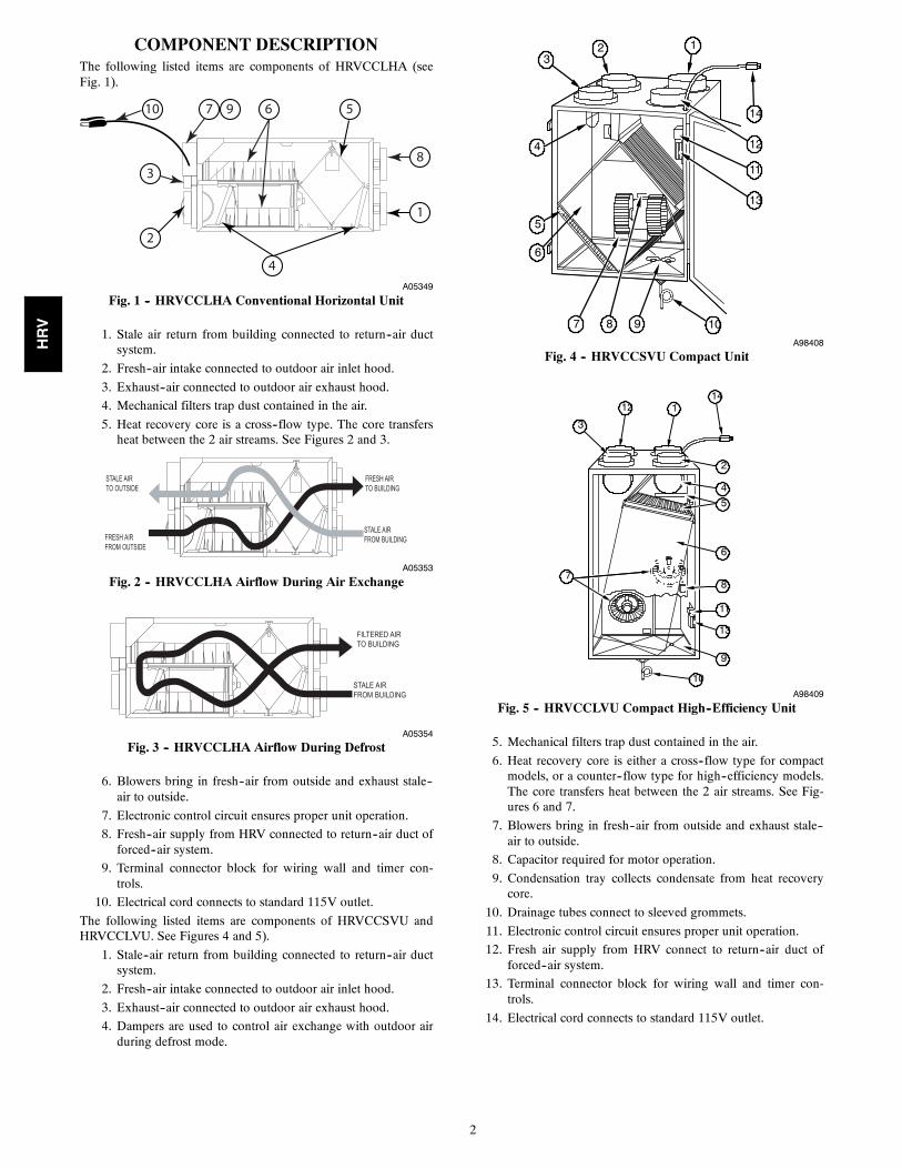
COMPONENT DESCRIPTIONThe following listed items are components of HRVCCLHA (seeFig. 1).
2
3
10
8
1
4
57 9 6
A05349
Fig. 1 -- HRVCCLHA Conventional Horizontal Unit
1. Stale air return from building connected to return--air ductsystem.
2. Fresh--air intake connected to outdoor air inlet hood.
3. Exhaust--air connected to outdoor air exhaust hood.
4. Mechanical filters trap dust contained in the air.
5. Heat recovery core is a cross--flow type. The core transfersheat between the 2 air streams. See Figures 2 and 3.
STALE AIR TO OUTSIDE
FRESH AIR TO BUILDING
FRESH AIR FROM OUTSIDE
STALE AIR FROM BUILDING
A05353
Fig. 2 -- HRVCCLHA Airflow During Air Exchange
FILTERED AIRTO BUILDING
STALE AIR FROM BUILDING
A05354
Fig. 3 -- HRVCCLHA Airflow During Defrost
6. Blowers bring in fresh--air from outside and exhaust stale--air to outside.
7. Electronic control circuit ensures proper unit operation.
8. Fresh--air supply from HRV connected to return--air duct offorced--air system.
9. Terminal connector block for wiring wall and timer con-trols.
10. Electrical cord connects to standard 115V outlet.
The following listed items are components of HRVCCSVU andHRVCCLVU. See Figures 4 and 5).
1. Stale--air return from building connected to return--air ductsystem.
2. Fresh--air intake connected to outdoor air inlet hood.
3. Exhaust--air connected to outdoor air exhaust hood.
4. Dampers are used to control air exchange with outdoor airduring defrost mode.
4
5
10
32 1
11
13
7
14
12
8 9
6
A98408
Fig. 4 -- HRVCCSVU Compact Unit
112
3
14
2
4
6
11
13
8
9
10
7
5
A98409
Fig. 5 -- HRVCCLVU Compact High--Efficiency Unit
5. Mechanical filters trap dust contained in the air.
6. Heat recovery core is either a cross--flow type for compactmodels, or a counter--flow type for high--efficiency models.The core transfers heat between the 2 air streams. See Fig-ures 6 and 7.
7. Blowers bring in fresh--air from outside and exhaust stale--air to outside.
8. Capacitor required for motor operation.
9. Condensation tray collects condensate from heat recoverycore.
10. Drainage tubes connect to sleeved grommets.
11. Electronic control circuit ensures proper unit operation.
12. Fresh air supply from HRV connect to return--air duct offorced--air system.
13. Terminal connector block for wiring wall and timer con-trols.
14. Electrical cord connects to standard 115V outlet.
HRV
3
STALE AIRFROM BUILDING
FRESH AIRTO BUILDING
FRESH AIRFROM OUTSIDE
STALE AIRTO OUTSIDE
A92382
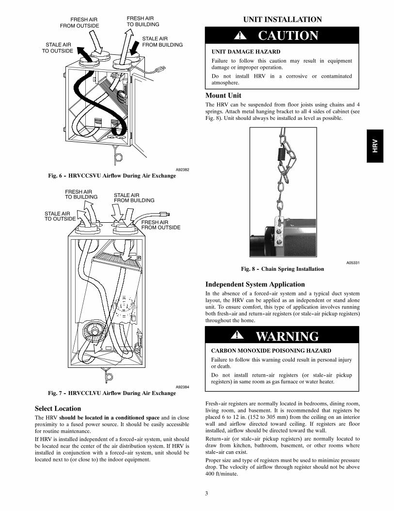
Fig. 6 -- HRVCCSVU Airflow During Air Exchange
STALE AIRFROM BUILDING
FRESH AIRTO BUILDING
FRESH AIRFROM OUTSIDE
STALE AIRTO OUTSIDE
A92384
Fig. 7 -- HRVCCLVU Airflow During Air Exchange
Select LocationThe HRV should be located in a conditioned space and in closeproximity to a fused power source. It should be easily accessiblefor routine maintenance.
If HRV is installed independent of a forced--air system, unit shouldbe located near the center of the air distribution system. If HRV isinstalled in conjunction with a forced--air system, unit should belocated next to (or close to) the indoor equipment.
UNIT INSTALLATION
UNIT DAMAGE HAZARD
Failure to follow this caution may result in equipmentdamage or improper operation.
Do not install HRV in a corrosive or contaminatedatmosphere.
CAUTION!
Mount UnitThe HRV can be suspended from floor joists using chains and 4springs. Attach metal hanging bracket to all 4 sides of cabinet (seeFig. 8). Unit should always be installed as level as possible.
A05331
Fig. 8 -- Chain Spring Installation
Independent System ApplicationIn the absence of a forced--air system and a typical duct systemlayout, the HRV can be applied as an independent or stand aloneunit. To ensure comfort, this type of application involves runningboth fresh--air and return--air registers (or stale--air pickup registers)throughout the home.
CARBON MONOXIDE POISONING HAZARD
Failure to follow this warning could result in personal injuryor death.
Do not install return--air registers (or stale--air pickupregisters) in same room as gas furnace or water heater.
! WARNING
Fresh--air registers are normally located in bedrooms, dining room,living room, and basement. It is recommended that registers beplaced 6 to 12 in. (152 to 305 mm) from the ceiling on an interiorwall and airflow directed toward ceiling. If registers are floorinstalled, airflow should be directed toward the wall.
Return--air (or stale--air pickup registers) are normally located todraw from kitchen, bathroom, basement, or other rooms wherestale--air can exist.
Proper size and type of registers must be used to minimize pressuredrop. The velocity of airflow through register should not be above400 ft/minute.
HRV
4
INSULATED DUCT CONNECTINGFRESH AIR & EXHAUST TOOUTSIDE
A
3 ft / .9 m MIN
FURNACE
REARINLET HOOD
6 ft / 1.8 m
EXHAUST HOOD
18" / 457 mm
ERV
NOTE: Supply & exhaust ducts haveinternal balancing dampersthat must be adjusted.
GROUND LEVEL
B
NOTE: A + B = Not less than 10 ft / 3 m
A07282
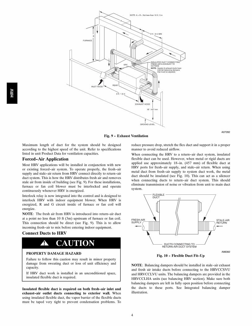
Fig. 9 -- Exhaust Ventilation
Maximum length of duct for the system should be designedaccording to the highest speed of the unit. Refer to specificationslisted in unit Product Data for ventilation capacities.
Forced--Air ApplicationMost HRV applications will be installed in conjunction with newor existing forced--air system. To operate properly, the fresh--airsupply and stale--air return from HRV connect directly to return--airduct system. This is how the HRV distributes fresh air and removesstale air from inside of building (see Fig. 9). For these installations,furnace or fan coil blower must be interlocked and operatecontinuously whenever HRV is energized.
Interlock relay is now integrated into the control and is designed tointerlock HRV with indoor equipment blower. When HRV isenergized, R and G circuit inside of furnace or fan coil willenergize.
NOTE: The fresh air from HRV is introduced into return--air ductat a point no less than 10 ft (3m) upstream of furnace or fan coil.This connection should be direct (see Fig. 9). This is to allowincoming fresh--air to mix before entering indoor equipment.
Connect Ducts to HRV
PROPERTY DAMAGE HAZARD
Failure to follow this caution may result in minor propertydamage from sweating duct or loss of unit efficiency andcapacity.
If HRV duct work is installed in an unconditioned space,insulated flexible duct is required.
CAUTION!
Insulated flexible duct is required on both fresh--air inlet andexhaust--air outlet ducts connecting to exterior wall. Whenusing insulated flexible duct, the vapor barrier of the flexible ductsmust be taped very tight to prevent condensation problems. To
reduce pressure drop, stretch the flex duct and support it in a propermanner to avoid reduced airflow.
When connecting the HRV to a return--air duct system, insulatedflexible duct can be used. However, when metal or rigid ducts areapplied use approximately 18--in. (457 mm) of flexible duct atHRV ports for fresh--air supply, and stale--air return. When usingmetal duct from fresh--air supply to system duct work, the metalduct should be insulated (see Fig. 10). This can act as a silencerwhen connecting ducts to return--air duct system. This shouldeliminate transmission of noise or vibration from unit to main ductsystem.
FLEXIBLEDUCT
FRESH-AIRSUPPLY
STALE-AIRRETURN
DUCTS CONNECTING TORETURN-AIR DUCT SYSTEM
A98382
Fig. 10 -- Flexible Duct Fit--Up
NOTE: Balancing dampers should be installed in stale--air exhaustand fresh air intake ducts before connecting to the HRVCCSVUand HRVCCLVU units. The balancing dampers are provided in theHRVCCLHA units (see balancing HRV section). Make sure bothbalancing dampers are left in fully open position before connectingthe ducts to these ports. See Integrated balancing damperillustration.
HRV
5
Condensate DrainTo connect condensate drain, proceed as follows:
1. Insert sleeved grommets into bottom of unit using the gas-ket washer and nut (see Fig. 11).
2. Cut two sections of plastic tubing, about 12--in. (305 mm)long and attach them to each drain.
3. Join the two short sections of plastic tubing to the “T” con-nector and the main tube as shown.
4. Make a loop in the tubing below the “T” connector to createa trap to prevent sewer gases from entering the ventilationsystem (see Fig. 11).
5. Connect unit drain to building’s main drain. Provide slightslope from unit for run--off.
A99268
Fig. 11 -- Condensate Drain With Loop Trap
Locate and Install Exterior HoodsIMPORTANT: To prevent condensation problems, insulatedflexible ducts are required on both fresh--air inlet and exhaust--airoutlet ducts connecting between HRV and exterior wall.
Fresh--air intake and stale--air exhaust must be separated by at least6 ft (1.8 m). Fresh--air intake must be positioned at least 10 ft. (3m) from nearest dryer vent, furnace exhaust, driveway, gas meter,or oil fill pipe. Fresh--air intake must be positioned as far aspossible from garbage containers and potential chemical fumes.When possible, it is advised to locate the intake and exhaust hoodson same side of house or building. The intake and exhaust hoodsshould never be located on interior corners or in dead air pockets(see Fig. 9). Both intake and exhaust hoods must be 18 in. (457mm) from ground and at least 12 in. (305 mm) above anticipatedsnow level.
After selecting proper hood locations, make appropriate size holethrough exterior wall, pass flexible duct through hole and inserthood tube into duct. Tape duct vapor barrier tightly around hoodtube and insert assembly back into wall and fasten securely.
WALL CONTROLLocationThe HRV wall controls are unique to HRV and must be installedfor proper unit operation.
Four wall control options are available:
1. Basic Control
2. OneTouch Control
3. Standard Control
4. Automatic Control
Basic Control OperationThe basic control contains a 3 position slide switch which is usedto manually select OFF, LOW, and HIGH speed blower operation.
The unit operates continuously when LOW or HIGH is selected(see Table 1).
Table 1 – Basic Control
MODE OPERATIONDAMPERPOSITION
FANSPEED
Off Off Closed to outside Off
LowAir exchange with
outside Open to outside Low
HighAir exchange with
outside Open to outside High
OneTouch Control OperationPress “Push” until the desired ventilation operation is selected.There are three selections: High, Low, Intermittent. The powerindicator light indicates which mode has been selected. See Table2.
Table 2 – OneTouch Push Button Control
MODE OPERATIONDAMPERPOSITION
FANSPEED
Off Off Closed to outside Off
LowAir exchange with
outside Open to outside Low
IntermittentAir exchange with
outside Open to outside Low
HighAir exchange with
outside Open to outside High
1. HIGH: This mode is recommended for the removal of ex-cess pollutants and humidity. The ventilator will operate atits maximum speed continuously. The power indicator lightwill be lit red when this mode is selected.
2. LOW: This mode is recommended for normal daily opera-tion. The ventilator will operate at minimum speed continu-ously. The power indicator light will be lit yellow when thismode is selected.
3. INTERMITTENT: This mode is recommended when theinside air is too dry in the heating season or too humid inthe cooling season. The ventilator will operate at its minim-um speed for 20 minutes per hour and be off for 40 minutesper hour. The power indicator light will be lit green whenthis mode is selected.
4. OFF: To turn the ventilator off, press “Push” until the powerindicator light is turned off.
Standard Control OperationThe standard wall control has 3 basic modes of operation, OFF,LOW, and INTERMITTENT. Be sure that all modes of operationare fully functional. See Table 3 indicating standard controloperation.
1. With switch off, ERV/HRV is inoperative and the LED isout.
2. With switch on LOW, ERV/HRV continuously exchangesair with outside. If control is satisfied, blower will run inlow speed, otherwise, blower will run on high speed. TheLED is illuminated all the time.
3. With switch on INTERMITTENT, the ERV/HRV ex-changes air with outside on high--speed blower, and unitshuts down when control is satisfied. The ON LED is illu-minated all the time, and AIR EXCHANGE LED is illu-minated only when unit is running. This mode is ideal formaintaining proper humidity levels when no one is home.
Automatic Control OperationThis control contains an adjustable dehumidistat and push buttonswitch to cycle between 3 modes of operation. There are 5 LEDs toindicate mode of operation (see Table 4).
HRV
6
Table 3 – Standard Control
MODE DEHUMIDISTATPOSITION OPERATION DAMPER
POSITION FAN SPEED ON LED AIR EXCHANGELED
Off Any Off Closed to outside Off Off Off
LowSatisfied
Air exchange with outside Open to outsideLow
On
OnCall for dehumidification High On
IntermittentSatisfied Off Closed to outside Off Off
Call for dehumidification Air exchange with outside Open to outside High On
Table 4 – Automatic Control
MODE DEHUMIDISTATPOSITION OPERATION DAMPER
POSITIONFANSPEED INDICATOR LEDs
Off Any Off Closed to outside Off Off
IntermittentSatisfied Off Closed to outside Off Intermittent ON
Call for dehumidificationAir exchange with outside Open to outside
High Intermittent and Exchange ON
ContinuousSatisfied Low
Continuous and Exchange ONCall for dehumidification High
RecirculationSatisfied Recirculation Closed to outside High Recirculation ON
Call for dehumidification Air exchange with outside Open to outside High Recirculation and Exchange ONMaintenance(open door) Any Off Closed to outside Off Maintenance
NOTE: This control is designed to be used primarily withinstallations which are independent of a forced air system.
1. Initially the switch is off. All LEDs are off and HRV is in-operative
2. First push of mode button puts HRV into intermittent mode.The HRV operates at high speed when there is a call for de-humidification. Intermittent and exchange LEDs are illu-minated. When dehumidistat is satisfied, HRV shuts downand exchange LED goes out.
3. Next push of mode button puts system in continuous mode.Continuous and exchange LEDs remain on. The HRV oper-ates at high--speed blower during calls for dehumidificationand low--speed when dehumidistat is satisfied.
4. Next push of mode button and exchange puts system in cir-culation mode. HRV operates in high speed at all times. Cir-culation LED remains on. When there is a call for dehumid-ification, exchange LED is on and HRV exchanges air withoutside. When dehumidistat is satisfied, HRV dampers closewhich recirculates indoor air. The exchange LED goes off.
5. The maintenance light illuminates every 3 months to indic-ate filter should be cleaned. It is reset by opening the door tothe HRV.
NOTE: The standard and automatic controls sense humidity nottemperature. Either control must be located in an area where it willcontinually monitor fresh air circulating within the home. InstallHRV wall control as close as possible to main system thermostatand follow same guidelines as installing a thermostat, (locateapproximately 5 ft. (1.5 m) above floor, mount on an insidepartitioning wall, etc.).
NOTE: The HRV may be controlled using the Infinity SystemControl. The HRV may be connected using either a NIM or a4--Zone Damper Module. See the appropriate instructions if usingthe NIM of a 4--Zone Damper Module for connection instructions.
Blower interlock relay is not needed for use with the Infinitysystem control. The Infinity System Control will simultaneouslycontrol the HRV and the indoor blower.
Push Button Timers may be used and are connected to the HRV asshown in Fig. 12. However, the Infinity system should be set tocontinuous fan to ensure that the fresh air is circulated in the home.In a Zoned System, at least one zone should be set to continuousfan.
The ventilator has four settings in heating mode and three settingsin cooling mode.
Heating:AUTO -- the ventilator selects the speed based on indoor humidityand outdoor temperature. It may cycle on/off every 30 minutesdepending on humidity and outside temperature.
LOW -- low speed all of the time.
HIGH -- high speed all of the time.
DEHUM -- will only turn on if humidity is 3% over setpoint. Thespeed is determined by indoor humidity and outdoor temperature.
HRV
7
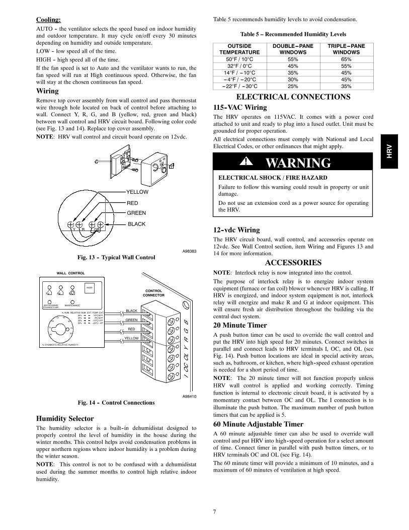
Cooling:AUTO -- the ventilator selects the speed based on indoor humidityand outdoor temperature. It may cycle on/off every 30 minutesdepending on humidity and outside temperature.
LOW -- low speed all of the time.
HIGH -- high speed all of the time.
If the fan speed is set to Auto and the ventilator wants to run, thefan speed will run at High continuous speed. Otherwise, the fanwill stay at the chosen continuous fan speed.
WiringRemove top cover assembly from wall control and pass thermostatwire through hole located on back of control before attaching towall. Connect Y, R, G, and B (yellow, red, green and black)between wall control and HRV circuit board. Following color code(see Fig. 13 and 14). Replace top cover assembly.
NOTE: HRV wall control and circuit board operate on 12vdc.
YELLOW
Y R GB
RED
GREEN
BLACK
A98383
Fig. 13 -- Typical Wall Control
% D’HUMIDITE RELATIVE HUMIDITY’
% HUM. RELATIVE HUM.55%45%35%30%
EXT. TEMP. EXT.
MODE
MAINTENANCEAIR EXCHANGEECHANGE D’AIR’
20
25
30
4050
60
70
80
10oC/50oF0oC/32oF
–10oC/14oF–20oC/– 4oF
CONTROLCONNECTOR
WALL CONTROL
YELLOW
RED
GREEN
BLACK
A98410
Fig. 14 -- Control Connections
Humidity SelectorThe humidity selector is a built--in dehumidistat designed toproperly control the level of humidity in the house during thewinter months. This control helps avoid condensation problems inupper northern regions where indoor humidity is a problem duringthe winter season.
NOTE: This control is not to be confused with a dehumidistatused during the summer months to control high relative indoorhumidity.
Table 5 recommends humidity levels to avoid condensation.
ELECTRICAL CONNECTIONS115--VAC WiringThe HRV operates on 115VAC. It comes with a power cordattached to unit and ready to plug into a fused outlet. Unit must begrounded for proper operation.
All electrical connections must comply with National and LocalElectrical Codes, or other ordinances that might apply.
ELECTRICAL SHOCK / FIRE HAZARD
Failure to follow this warning could result in property or unitdamage.
Do not use an extension cord as a power source for operatingthe HRV.
! WARNING
12--vdc WiringThe HRV circuit board, wall control, and accessories operate on12vdc. See Wall Control section, item Wiring and Figures 13 and14 for more information.
ACCESSORIESNOTE: Interlock relay is now integrated into the control.
The purpose of interlock relay is to energize indoor systemequipment (furnace or fan coil) blower whenever HRV is calling. IfHRV is energized, and indoor system equipment is not, interlockrelay will energize and make R and G at indoor equipment. Thiswill ensure fresh air distribution throughout the building via thecentral duct system.
20 Minute TimerA push button timer can be used to override the wall control andput the HRV into high speed for 20 minutes. Connect switches inparallel and connect leads to HRV terminals I, OC, and OL (seeFig. 14). Push button locations are ideal in special activity areas,such as, bathroom, or kitchen, where high--speed exhaust operationis needed for a short period of time.
NOTE: The 20 minute timer will not function properly unlessHRV wall control is applied and working correctly. Timingfunction is internal to electronic circuit board, it is activated by amomentary contact between OC and OL. The I connection is toilluminate the push button. The maximum number of push buttontimers that can be applied is 5.
60 Minute Adjustable TimerA 60 minute adjustable timer can also be used to override wallcontrol and put HRV into high--speed operation for a select amountof time. Connect timer in parallel with push button timers, or toHRV terminals OC and OL (see Fig. 14).
The 60 minute timer will provide a minimum of 10 minutes, and amaximum of 60 minutes of ventilation at high speed.
HRV
8
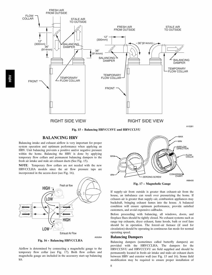
12”(300mm)
FLOWCOLLAR
FRONT
FRESH AIRFROM OUTSIDE
STALE AIRTO OUTSIDE
TEMPORARYFLOW COLLAR
TEMPORARYFLOW COLLAR
RIGHT SIDE VIEW RIGHT SIDE VIEW
36”(914mm) 36”
(914mm)
12”(300mm)
36”(914mm)
FRESH AIRFROM OUTSIDE
STALE AIRTO OUTSIDE
TEMPORARYFLOW COLLAR
FRONT
BALANCINGDAMPER
BALANCINGDAMPER BALANCING
DAMPER
A10281
Fig. 15 -- Balancing HRVCCSVU and HRVCCLVU
BALANCING HRVBalancing intake and exhaust airflow is very important for propersystem operation and optimum performance when applying anHRV. Unit balancing prevents a positive and/or negative pressurewithin the home. Balancing the HRV is done by applyingtemporary flow collars and permanent balancing dampers to thefresh air intake and stale air exhaust ducts (See Fig. 15).
NOTE: Temporary flow collars are not needed with the newHRVCCLHA models since the air flow pressure taps areincorporated in the access door (see Fig. 16).
Fresh air flow
Exhaust Air FlowA05264
Fig. 16 -- Balancing HRVCCLHA
Airflow is determined by connecting a magnehelic gauge to thetemporary flow collar (see Fig. 17). Both flow collars andmagnehelic gauge are included in the accessory start--up balancingkit.
MAX
MIN
AIRFLOWDIRECTION
CONVERSIONCHART
MAX
MINZEROING SCREW
FLOWCOLLAR
A98400
Fig. 17 -- Magnehelic Gauge
If supply--air from outside is greater than exhaust--air from thehouse, an imbalance can result over pressurizing the home. Ifexhaust--air is greater than supply--air, combustion appliances maybackdraft, bringing exhaust fumes into the house. A balancedcondition will ensure optimum performance, provide satisfiedcustomers, and avoid expensive callbacks.
Before proceeding with balancing, all windows, doors, andfireplace flues should be tightly closed. No exhaust systems such asrange top exhausts, dryer exhaust, fume hoods, bath or roof fansshould be in operation. The forced--air furnace (if used forcirculation) should be operating in continuous fan mode for normaloperating speed.
Balancing DampersBalancing dampers (sometimes called butterfly dampers) areprovided with the HRVCCLHA. The dampers for theHRVCCSVU and HRVCCLVU are field supplied and should bepermanently located in fresh--air intake and stale--air exhaust ductsbetween HRV and exterior wall (see Fig. 15 and 16). Some fieldmodification may be required to ensure proper installation of
HRV
9
balancing dampers while located in flexible duct. Insulating overthese dampers is strongly recommended after balancing is completeto prevent condensation problems.
Flow CollarFlow collars are temporary and should be installed as close to HRVas possible and in straightest sections of duct to ensure accuracy(see Fig. 16). If only 1 flow collar is available, install collar instale--air duct of HRV, and record airflow. Next, install collar in thefresh--air duct and record airflow. If 2 flow collars are available, itwill be much easier to read airflow and properly adjust dampers tobalance unit.
With speed control at maximum speed (high--speed operation) andcontinuous air exchange occurring with outside, connect hosesfrom flow collar to a magnehelic gauge (see Fig. 17). The gaugemust be leveled and zeroed before use to read accurately. If needlefalls below zero, reverse hose connections.
Measure exhaust air first, it is typically the lowest pressure due tonature of system and duct work. Next, measure fresh air. If fresh airreading is higher than exhaust reading, adjust damper until readingis same. If reading is lower, return to exhaust damper and adjust toobtain same reading. You can use label on flow collar to convertstatic pressure into airflow.
Once HRV is balanced and dampers are adjusted to equalizeairflow, use tape or drive screws to prevent damper blades frommoving. Remove flow collars and secure ducts. This procedureshould be repeated to ensure unit is balanced properly.
NOTE: The flow collar directional arrow (on flow collar) must beoriented in the airflow direction of unit.
NOTE: Some field modification may be required to ensure propertemporary installation of flow collar during balancing wheninsulated flexible duct is used.
VENTILATION EVALUATION
UNIT DAMAGE HAZARD
Failure to follow this caution may result in reduced unitefficiency, capacity or unit life.
DO NOT use HRV during construction of a house or whensanding drywall. This type of dust may damage system.
CAUTION!
When ventilation requirement is determined, use Product DataSheets to reference unit airflow delivery and performance.
The ventilation capacity of an HRV unit while at maximum speedis defined according to greatest total airflow required. Thesemethods are derived from the Canadian National Building Code1995 version and the CSA F326.1 revision.
The following 2 methods can be used to evaluate the approximateventilation needs of a house. Accuracy of calculations aredependent upon the information available and knowing criticalmeasurements of the structure (see Fig. 18).
METHOD 1
To calculate approximate ventilation:
The sum of rooms X 10 CFM per room, plus 20 CFM for amaster bedroom or basement.
Example: 11 rooms X 10 CFM + 2 X 20 CFM = 150 CFM.
NOTE: The master bedroom and basement are not included infirst part of this equation, but figured in at second part of equation.
METHOD 2
To calculate approximate ventilation:
Referencing same example (see Fig. 18).
Total cu ft X 0.3 per hr = total. Take total and divide by 60 toget CFM.
Example:1320 sq ft X 8 ft in height = 10560 cu ft per floor10560 cu ft x 3 floors = 31680 total cu ft in house31680 cu ft X 0.3 air change per hr = 9500 cu ft9500 cu ft ÷ 60 minimum per hr = 160 CFM.
Conclusion: The total amount of air flow needed is 160 CFM. Thisfalls within airflow range of a HRVCCLHA1150 size unit.
BASEMENT
MASTERBEDROOM
WASH-ROOM
#1
WASH-ROOM
#2BEDROOM
#3
BEDROOM#5
BEDROOM#4
1320 sq ft (125 sq m) 1320 sq ft (125 sq m)
LIVING ROOM#6
FAMILY ROOM#10
KITCHEN#9
LAUNDARYROOM
#8
WASH-ROOM
#7
DINING ROOM#11
1320 sq ft (125 sq m)
A98388
Fig. 18 -- Floor Plan Example
HRV
10
BL
KB
LA
CK
BL
UB
LU
E
BR
NB
RO
WN
GR
NG
RE
EN
GR
YG
RY
OR
GO
RA
NG
E
RE
DR
ED
WH
TW
HIT
E
YE
LY
EL
LO
W
CO
LO
R C
OD
E
Ca
racté
ristiqu
e c
ritiqu
e
Cri
tical ch
ara
cte
ristic
CO
NN
EC
TIO
N D
IAG
RA
M
1 2 3
4 5 6
7 8 9
123
3456789
J3
J2 J1
J4
F FIOCOLB R YG
FA
N M
OT
OR
DA
MP
ER
MO
TO
R
12
0V
, 6
0H
z
NE
MA
-15
P
5-1
5 P
LU
G(n
ote
4)
MO
TO
R
CA
PA
CIT
OR
BR
N
BR
N
BL
U
RE
D
BL
U
BL
U
WH
T
NC
GR
Y
OR
G
BL
U
YE
L
BL
K
WH
T
-t
DE
FR
OS
T T
EM
PE
RA
TU
RE
S
EN
SO
R
(CO
MM
ON
)
(NO
CO
NT
AC
T)
(NC
CO
NT
AC
T)
BL
K
GR
N
RE
D
YE
L
RE
D
BL
K
YE
L
WA
LL
CO
NT
RO
L
NO
TE
1
OV
ER
RID
E
OP
TIO
NA
L
Connect to
G o
n F
urn
ace/F
ancoil
Connect to
G o
n T
herm
osta
t
Co
nn
ect
to R
on
Fu
rna
ce
/Fa
nco
il
ME
D
LO
NE
UT
RA
L
FA
N M
OT
OR
DA
MP
ER
MO
TO
R
HI
LO
K5
RE
LA
Y
K1
RE
LA
Y
K2
RE
LA
Y
K3
RE
LA
Y
ME
D
J1-4
J1-6
J1-9
J3-2
J3-1
J1-3
J1-1
J1-8
J1-2
120V
, 60H
z R
ET
UR
N
AIR
HA
ND
LE
R
FA
N IN
TE
RLO
CK
24
VA
C
CLA
SS
2 C
IRC
UIT
ON
LY
LO
GIC
DIA
GR
AM
LIN
E V
OL
TA
GE
CL
AS
S 2
LO
W V
OL
TA
GE
AN
D F
IEL
D W
IRIN
G
G ABCDEF
GA
BC
DE
F
RE
D
321
HI
OR
G
GR
Y
GR
N
321
GR
N
GR
N
GR
NG
RN
FU
NC
TIO
N T
AB
LE
RE
LA
Y
MO
DE
K1
K2
K3
K5
Inte
rmitte
nt (2
0 m
in p
er
hour)
00
01
Exchange L
ow
10
10
Exchange H
igh
11
10
Circu
latio
n L
ow
10
11
Circu
latio
n H
igh
11
11
De
fro
st C
ycle
11
11
OF
F0
00
1
0 =
Rela
y c
oil
is d
e-e
nerg
ized
1 =
Rela
y c
oil
is e
nerg
ized
De
fro
st cycle
s (
min
ute
s)
(Defr
ost / ventila
tion)
JU
MP
ER
TA
BL
E2
3F
5F
-17
F
JU
1-A
JU
1-B
JU
1-C
JU
1-D
JU
1-E
JU
1-F
JU
1-G
MO
DE
L-5
C-1
5C
-27
C
OU
TO
UT
OU
TO
UT
ININ
OU
TH
RV
CC
LH
A1150
6/3
26/3
26/2
0
OU
TO
UT
OU
TO
UT
ININ
OU
TH
RV
CC
LH
A1250
6/3
26/3
26/2
0
OU
TO
UT
OU
TO
UT
INO
UT
OU
TE
xte
nded d
efr
ost all
mo
de
ls10
/30
10/2
010/1
5
WA
RN
ING
EL
EC
TR
ICA
LS
HO
CK
HA
ZA
RD
Dis
connect pow
er
befo
re s
erv
icin
g /
ma
inte
nan
ce
or
fie
ld w
irin
g.
Re
insta
ll a
ll
pan
els
be
fore
op
era
ting
. F
ailu
re t
o d
o s
o
ca
n r
esu
lt in d
ea
th o
r e
lectr
ica
l sh
ock.
AV
ER
TIS
SE
ME
NT
RIS
QU
E D
E C
HO
C É
LE
CT
RIQ
UE
Dé
bra
nch
ez la s
ourc
e d
'alim
en
tation
éle
ctr
iqu
e a
va
nt
l'entr
etie
n,
la
rép
ara
tio
n o
u le
ra
ccord
em
ent
sur
pla
ce
. R
ep
lacez t
ou
s le
s p
ann
eau
x
avan
t d
'utilis
er.
Le n
on-r
espe
ct d
e c
es
instr
uction
s p
eut
ca
use
r un
dé
cè
s o
u
un c
hoc é
lectr
iqu
e
AD
VE
RT
EN
CIA
PE
LIG
RO
DE
CH
OQ
UE
EL
ÉC
TR
ICO
De
scon
ecte
el su
min
istr
o d
e e
ne
rgía
ante
s d
e r
ep
ara
r, d
e m
an
ten
er
o d
e
ca
ble
ar
in s
itu
. V
uelv
a a
co
loca
r to
dos
los p
ane
les a
nte
s d
e h
ace
r lo
fun
cio
na
r. N
o s
eg
uir
esta
s
instr
uccio
ne
s p
ued
e c
ausa
r la
mu
ert
e o
ch
oq
ue
elé
ctr
ico.
NO
TE
S
1-
CO
NT
RO
LS
AV
AIL
AB
LE
SE
E T
HE
IN
ST
RU
CT
ION
MA
NU
AL
2-
IF A
NY
OF
TH
E O
RIG
INA
L W
IRE
AS
SU
PP
LIE
D
MU
ST
BE
RE
PL
AC
ED
, U
SE
TH
E S
AM
E O
R E
QU
IVA
LE
NT
WIR
E.
3-
FA
CT
OR
Y S
ET
WIR
ING
FO
R B
LO
WE
R S
PE
ED
IS
HIG
H A
ND
LO
W S
PE
ED
. M
ED
IUM
SP
EE
D C
AN
BE
SE
LE
CT
ED
IN
ST
EA
D O
F
LO
W S
PE
ED
. D
ISC
ON
NE
CT
RE
D W
IRE
FR
OM
MO
TO
R(S
) R
ED
TA
P A
ND
CO
NN
EC
T T
O M
OT
OR
(S)
BL
UE
TA
P.
4-
US
E S
PE
CIF
IED
UL
LIS
TE
D/C
SA
CE
RT
IFIE
D L
INE
FU
SE
.
FO
R A
LL
UN
ITS
: L
ITT
EL
FU
SE
(2
25
00
3),
2A
G F
AS
T-A
CT
ING
FU
SE
,
22
4/2
25
SE
RIE
S,
RA
TIN
G:
3 A
F
Do
or
inte
rlo
ck
sw
itch
J1-3
120V
, 60H
z L
INE
F
BLK
A09104
Fig
.19
--W
irin
gD
iagr
amfo
rM
odel
s:H
RV
CC
LH
A11
50,a
ndH
RV
CC
LH
A12
50HRV
11
WA
RN
ING
ELEC
TRIC
AL
SHO
CK
HA
ZAR
DD
isco
nnec
t pow
er b
efor
e se
rvic
ing
/ m
aint
enan
ce o
r fie
ld w
iring
. Rei
nsta
ll a
ll pa
nels
bef
ore
oper
atin
g. F
ailu
re to
do
so
can
resu
lt in
dea
th o
r ele
ctric
al s
hock
.
AVE
RTI
SSEM
ENT
RIS
QU
E D
E C
HO
C É
LEC
TRIQ
UE
Déb
ranc
hez
la s
ourc
e d'
alim
enta
tion
élec
triqu
e av
ant l
'ent
retie
n, la
ré
para
tion
ou le
racc
orde
men
t sur
pl
ace
. Rep
lace
z to
us le
s pa
nnea
ux
avan
t d'u
tilis
er. L
e no
n-re
spec
t de
ces
inst
ruct
ions
peu
t cau
ser u
n dé
cès
ou
un c
hoc
élec
triqu
e
AD
VER
TEN
CIA
PELI
GR
O D
E C
HO
QU
E EL
ÉCTR
ICO
Des
cone
cte
el s
umin
istro
de
ener
gía
ante
s de
repa
rar,
de m
ante
ner o
de
cabl
ear i
n si
tu. V
uelv
a a
colo
car t
odos
lo
s pa
nele
s an
tes
de h
acer
lo
func
iona
r. N
o se
guir
esta
s in
stru
ccio
nes
pued
e ca
usar
la m
uerte
o
choq
ue e
léct
rico.
BLK
BLA
CK
BLU
BLU
E B
RN
BR
OW
N G
RN
GR
EEN
GR
YG
RY
OR
GO
RA
NG
E R
ED
RE
D W
HT
WH
ITE
YE
LY
ELLO
W
CO
LOR
CO
DE
Car
acté
ristiq
ue c
ritiq
ueC
ritic
al c
hara
cter
istic
FAN
MO
TOR
2(N
ote
3)
FAN
MO
TOR
1
DA
MPE
R M
OTO
R 1
DA
MPE
R M
OTO
R 2
HI
LO HI
LO
K5
REL
AY
K1
REL
AY
K2
REL
AY
K3
REL
AY
MED
MED
J1-4
J1-6
J1-9
J3-2
J3-1
J1-3
J1-1
J1-8
J1-2
120V
, 60H
z R
ETU
RN
AIR
HAN
DLE
R
FAN
INTE
RLO
CK
24 V
AC
CLA
SS
2 C
IRC
UIT
ON
LY
LOG
IC D
IAG
RA
M
GA
BC
DE
F
FUN
CTI
ON
TA
BLE
REL
AY
MO
DE
K1
K2
K3
K5
Inte
rmitt
ent (
20 m
in p
er h
our)
00
01
Exc
hang
e Lo
w1
01
0E
xcha
nge
Hig
h1
11
0C
ircul
atio
n Lo
w1
01
1C
ircul
atio
n H
igh
11
11 1
11
1elcy
C tsorfeD
10
00
FFO 0
= R
elay
coi
l is
de-e
nerg
ized
1 =
Rel
ay c
oil i
s en
ergi
zed
Def
rost
cyc
les
(min
utes
)(D
efro
st /
vent
ilatio
n)JU
MP
ER
TA
BLE
23°F
5 °F
-17°
FJU
1-A
JU1-
BJU
1-C
JU1-
DJU
1-E
JU1-
FJU
1-G
MO
DE
L-5°C
-15°
C-2
7°C
OU
TO
UT
OU
TO
UT
ININ
OU
TH
RV
CC
SV
U11
506/
326/
326/
20O
UT
OU
TO
UT
OU
TIN
INO
UT
HR
VC
CS
VU
1200
6/32
6/32
6/20
OU
TO
UT
OU
TO
UT
ININ
OU
TH
RV
CC
LVU
1330
6/32
6/32
6/20
OU
TO
UT
OU
TO
UT
INO
UT
OU
TE
xten
ded
defro
st a
ll m
odel
s10
/30
10/2
010
/15
LIN
E V
OLT
AG
E
CLA
SS
2 L
OW
VO
LTA
GE
A
ND
FIE
LD W
IRIN
GF
Doo
r int
erlo
cksw
itch
J1-3
120V
, 60H
z LI
NE
NO
TES
1-C
ON
TRO
LS A
VA
ILA
BLE
SE
E T
HE
INS
TRU
CTI
ON
MAN
UAL
.
2-F
AN
MO
TOR
2 IS
US
ED
ON
LY W
ITH
HR
VC
CLV
U12
00 A
ND
HR
VC
CLV
U13
30.
3-D
AM
PE
R M
OTO
R 2
IS U
SED
ON
LY W
ITH
HR
VC
CLV
U12
00 A
ND
HR
VC
CLV
U13
30.
4-I
F AN
Y O
F TH
E O
RIG
INA
L W
IRE
AS
SU
PP
LIE
D M
US
T BE
RE
PLA
CE
D, U
SE
T
HE
SA
ME
OR
EQ
UIV
ALE
NT
WIR
E.
5-F
AC
TOR
Y S
ET W
IRIN
G F
OR
BLO
WER
SPE
ED
IS H
IGH
AN
D L
OW
SPE
ED
.
ME
DIU
M S
PEE
D C
AN
BE
SE
LEC
TED
INS
TEA
D O
F LO
W S
PE
ED.
D
ISC
ON
NEC
T R
ED W
IRE
FRO
M M
OTO
R(S
) RED
TAP
AN
D C
ON
NEC
T TO
MO
TOR
(S) B
LUE
TA
P.
6-P
OW
ER S
UP
PLY
CO
NN
EC
TIO
N W
ITH
F1
IN L
INE
FU
SE
IS N
OT
AP
PLIC
AB
LE W
ITH
HR
VC
CLV
U13
30 U
NIT
. FO
R A
LL O
THER
UN
ITS,
USE
S
PEC
IFIE
D U
L LI
STE
D/C
SA C
ER
TIFI
ED F
USE
:LI
TTE
LFU
SE (2
25 0
03),
2AG
FA
ST-
AC
TIN
G F
US
E, 2
24/2
25
S
ER
IES
, RA
TIN
G: 3
A
7-P
OW
ER
SU
PPLY
CO
NN
ECTI
ON
IS U
SED
ON
LY W
ITH
HR
VC
CLV
U13
30 U
NIT
.
8-F
2 AN
D F
3 IN
LIN
E FU
SE IS
ON
LY U
SED
WIT
H H
RVC
CLV
U13
30 U
NIT
.U
SE S
PEC
IFIE
D U
L LI
STE
D/C
SA
CE
RTI
FIE
D F
US
E:
LITT
ELF
US
E (3
12 0
05),
3AG
FA
ST-
AC
TIN
G F
US
E, 3
12/3
18S
ER
IES
, RA
TIN
G: 5
A
OR
CO
OP
ER B
US
SM
ANN
(AG
C-5
), 3
AG
FA
ST-
AC
TIN
G F
US
E, A
GC
SE
RIE
S, R
ATI
NG
: 5 A
CO
NN
ECTI
ON
DIA
GR
AM
1 2 3
4 5 6
7 8 9
123
3456789
J3
J2 J1
J4
F FIOCOLB R YG
GR
Y
OR
G
BLUYEL
-t
DEF
RO
ST T
EMPE
RA
TUR
E SE
NSO
R
(CO
MM
ON
)
(NO
CO
NTA
CT)
(NC
CO
NTA
CT)
BLK
GR
N
RED YE
L
RED
BLK YE
L
WA
LL C
ON
TRO
LN
OTE
1
OV
ER
RID
EO
PTIO
NA
L
AIR
HA
ND
LER
FA
N IN
TER
LOC
K24
VA
C
CLA
SS
2 C
IRC
UIT
ON
LY
G ABCDEF
RE
D
FAN
MO
TOR
2(N
ote
2)
FAN
MO
TOR
1
DAM
PER
MO
TOR
2(N
ote
3)
DAM
PER
MO
TOR
1
21 2121 21
MO
TOR
C
AP
ACIT
OR
BR
N
BR
N
BR
N
BR
N
GR
Y
OR
G
BLU
RED
GR
Y
OR
G
BLU
RED YE
L
BLU
YE
L
BLU
GR
N
GR
N
NC
NC
HI
ME
D
LO HI
ME
D
LO
Not
e 8
F2
Not
e 8
F3
MO
TOR
CA
PAC
ITO
R
Not
e 6
Doo
r int
erlo
cksw
itch
BLK
WH
T
A B
F1
120V
, 60H
zN
EMA-
15P
5-15
PLU
G
A B
Not
e 7
Doo
r int
erlo
cksw
itch
BLK
WH
T12
0V, 6
0Hz
NE
MA
-15P
5-15
PLU
G
B A
CO
M
CO
M
A10265
Fig
.20
--W
irin
gD
iagr
amfo
rM
odel
s:H
RV
CC
SVU
1150
,HR
VC
CSV
U12
00an
dH
RV
CC
LV
U13
30
HRV
12
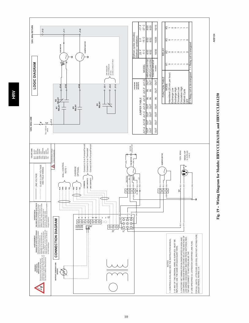
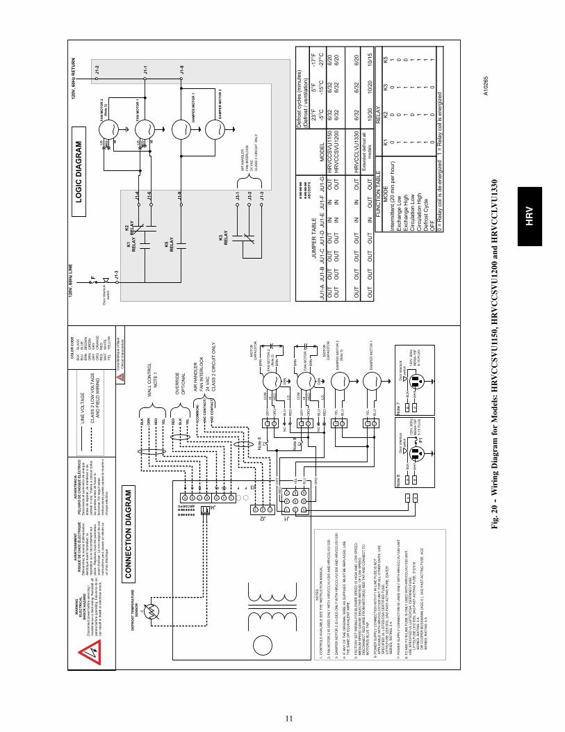
CONTROL BOARD OPERATIONBoard FunctionNOTE: To ensure proper operation of HRV, configurationjumpers are located on electronic control board and must matchconfiguration setup shown on Fig. 19 and 20 under Jumper Table.
Jumpers are factory set and do not require any changes unlesscontrol board is replaced. If control board is replaced, or youencounter unusual start--up operation, check jumpers to make surethey are located properly (see Fig. 19 and 20).
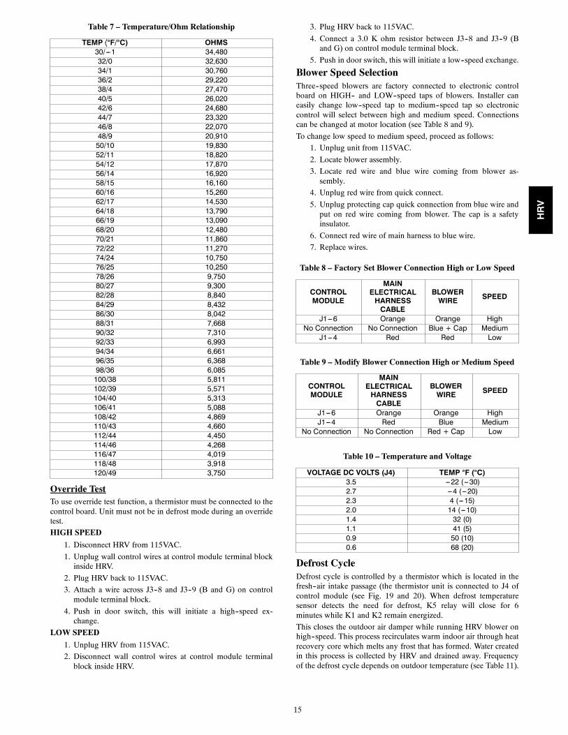
DefrostThe HRV continually monitors the outside air temperature. If theoutside air is at or below 23°F (--5°C), the HRV will initiate adefrost cycle by closing the outside air damper and recirculatingwarm indoor air through the heat recovery core. This happensevery 32 min. with 6 minute defrost cycle. During this process,core is defrosted without the use of electric strip heat. At 5°F(--15°C), unit will defrost for 6 minutes every 32 min. At --17°F(--27°C), the unit will sense a need to defrost every 20 minutes witha 6 minute cycle. See the Troubleshooting section for a controllogic explanation. See Figures 2, 21 and 22.
STALE AIRFROM BUILDING
FILTERED AIRTO BUILDING
A92383
Fig. 21 -- HRVCCSVU Airflow DuringRecirculation and Defrost
STALE AIRFROM BUILDING
FILTERED AIRTO BUILDING
A92385
Fig. 22 -- HRVCCLVU Airflow DuringRecirculation and Defrost
Off and Intermittent/Off ModeWhen HRV is Off, K1 relay is open, and K5 relay is energizedwhich closes outside air damper (see Logic Diagram in Fig. 19 and20).
High--Speed Air ExchangeWhen high--speed air exchange occurs, K1 and K2 relays areenergized and K5 relay is de--energized. This opens low--speedcontacts, and closes high--speed contact on K2 relay. This alsoopens contact on K5 relay which opens outside air damper. Then,115VAC is applied between orange and gray wires on Molex plug(pins 1 and 6) and blower motor runs in high--speed operation (seeLogic Diagram in Fig. 19 and 20).
Low--Speed Air ExchangeWhen low--speed air exchange occurs, K1 Relay is energizedwhich closes the contacts. K2 and K5 relays are de--energized. Thiskeeps low--speed contacts closed and high--speed contacts open onK2 relay, and opens outdoor air damper. 120VAC is appliedbetween Red and Gray wires on Molex plug (pins 1 and 4) andblower motor runs in low--speed operation.
CARE AND MAINTENANCE
ELECTRICAL SHOCK HAZARD
Failure to follow this warning could result in personal injuryor death.
Before installing or servicing system, always turn off, tag andlockout main power to system. There may be more than 1disconnect switch.
! WARNING
CUT HAZARD
Failure to follow this caution may result in personal injury.
Sheet metal parts may have sharp edges or burrs. Use careand wear appropriate protective clothing and gloves whenhandling parts.
CAUTION!
DoorHRV door can be removed by unlatching brief case style latches,then slide door to the right and remove it from hinges. Door mustbe in place and secured shut for proper operation.
FilterFilters in HRV are washable and should be cleaned every 3months. Use a vacuum cleaner to remove heaviest portion ofaccumulated dust, then wash in lukewarm water. Allow filter tocompletely dry before reinstalling. A dirty air filter will causeexcessive strain on blower motor. Never operate unit without afilter. Vacuum out debris.
In addition, regularly check and clean screens on exterior intakeand exhaust hoods when necessary.
HRV
13
UNIT COMPONENT DAMAGE HAZARD
Failure to follow this caution may result in unit componentdamage.
DO NOT clean filters in a dishwasher and DO NOT dry themwith a heating appliance or permanent damage will result.
CAUTION!
Blower Motor and WheelHRV blower motors are factory lubricated for life. Lubricatingbearings is not recommended. However, inspect and clean anyaccumulated dirt and grease from blower motor and wheelannually.
Cleaning the CoreHRV unit is equipped with special heat recovery core and must behandled with care. We recommend that it be washed once a yearfollowing the season of most intense use. This will ensuremaximum efficiency of the plastic partitions within the core.
Allow heat recovery core to soak for 3 hours in a solution of warmwater and mild soap. Rinse under stream of water. Hot water andstrong detergent will damage core and should NOT be used.
TROUBLESHOOTING
ELECTRICAL SHOCK HAZARD
Failure to follow this warning could result in personal injuryor death.
Before installing or servicing system, always turn off, tag andlockout main power to system. There may be more than 1disconnect switch.
! WARNING
CUT HAZARD
Failure to follow this caution may result in personal injury.
Sheet metal parts may have sharp edges or burrs. Use careand wear appropriate protective clothing and gloves whenhandling parts.
CAUTION!
NOTE: Reference Table 6 Troubleshooting Chart
This can be a quick guide in resolving unit problems. It is alsorecommended to review and understand Wall Control BoardOperation and Care and Maintenance sections before continuing.There are 3 main parts to focus on when troubleshooting HRVunit: wall control, electronic control board and blower motor.
Wall Control
Typically, the wall control is either good or it is bad. Use Table 1,2, 3, or 4 to determine if wall control is operating correctly. UseFig. 13to check control wire connections.
NOTE: The electronic control board and wall control operate on12vdc.
Control Board
Electronic control board must have wall control attached beforeunit will function properly (except for units equipped with manualswitch such as the new horizontal units). Also, configurationjumpers located on control board must match configuration setupshown on Fig. 20 under Jumper Table. In addition, outside airthermistor must be connected to control board for it to operateproperly. See Table 7, Temperature/Ohm Relationship, for validtemperature range.
Blower Motor
The HRV blower motor operates on 115VAC, with 2--speedoperation.
The easiest way to check blower speed operation is to use the wallcontrol and initiate a low--speed blower and high--speed bloweroperation.
NOTE: If there is a short circuit or an open circuit at thermistor,CPU will go into a 5 minute defrost cycle every 20 minutes. Thisfeature is not there on older board versions with 3 pin jumpers.
HRV
14
Be sure to unplug and inspect the unit before proceeding with these steps. Start with problem 1, then problem 2 and so on.
Table 6 – Troubleshooting
Problem: Possible causes: You should try this:
1. Unit does notwork.
S Erratic operation of the electroniccircuit.
S Unplug the unit. Wait for 30 seconds. Plug it back in.
S The breaker in the electrical panelmay be tripped.
S Reset breaker. If it trips again, unplug the unit and call an electrician.
S The door switch may be defectiveS Using a multimeter, check for power across the switch (the door switch
must be pushed in for this test). If there is no power, replace the switch.
S The circuit board may be defective.
S Jump “B” and “G” (BLACK and GREEN) or “B”and “R” (BLACK AND RED). If unit switches tohigh speed, remove the wall control and test itright beside the unit using another shorter wire. Ifthe wall control works there, change the wire. If itdoes not, change the wall control.
S The power cord fuse may be blown.
(Except for --1330 models.)
S Unplug the unit. Unscrew the fuse holder in the power cord. Check if thefuse is blown (the strand is broken). If the fuse is blown, replace the fuseaccording to the specifications on the wiring diagram.
S The fan motor may be defective.S Unplug the unit and disconnect the fan motor (4 wires). Supply 120 V
directly to the GREY and ORANGE wires of the fan motor. Replace themotor if not working.
S The 9--pin connector may have aloose connection.
S Unplug the unit and check to make sure all the crimp connections aresound. Check the fan motor and the damper actuator connections as well.
2. One fan motordoes not work.(--1330 modelsonly)
S The fan motor fuse F2 or F3 maybe blown.
S Unplug the unit. Unscrew the F2 and F3 fuse holders on the lower rightside of the unit and check if the fuses are blown (the strand is broken). Ifit is blown, replace the fuse according to the specifications on the wiringdiagram.
3. The damperactuator does notwork.
S The 9--pin connector may have aloose connection.
S Unplug the unit and check to make sure all the crimp connections aresecured. Check the damper actuator connections as well.
S The damper actuator may bedefective.
S Feed 120 V directly to the damper actuator. If the problem persists,replace the damper actuator.
S The circuit board may be defective. S Replace the circuit board if the problem is not solved by the above.
4. The wall controlwill not work.
S The wire in the wall OR the wallcontrol may be defective.
S Remove the wall control and test it right beside the unit using anothershorter wire. If the wall control works there, change the wire. If it doesnot, change the wall control.
S The wires may be in reverseposition.
S Ensure that the color coded wires have been connected to theirappropriate places.
S The wires may be broken. S Inspect every wire and replace any that are damaged.
S There may be a short--circuit. S With the help of a multimeter, check for continuity.
5. The 20--minutelighted push--button switchdoesn’t work ORits indicator lightdoesn’t stay on.
S The switch may be defective.
S The wires may be defective ORmay not be connected properly.
S Jump the OL and OC terminals. If the unit switches to highspeed, then the wires are not the problem. Replace thepush--button.
S Ensure that the color--coded wires have been connected totheir appropriate places.
6. The defrost cycledoes not work(the fresh airduct is frozenOR the fresh airdistributed isvery cold.)
S Ice deposits may be hindering thedamper operation.
S Remove the ice.
S The damper rod or the port damperitself may be broken.
S Inspect these parts and replace if necessary.
S The damper actuator may bedefective.
S Plug in the unit and select “OFF”. Press the door switch and see if theport damper closes. If it does not close, feed 120V directly to the damperactuator. If the port damper still does not close, replace the damperactuator.
S The circuit board may be defective.
S Unplug the unit. Unplug the defrost sensor wire (see J4 on electricaldiagram). Plug the unit back in. Select “MIN” and make sure the unit isadjusted for low speed operation. Wait 3 minutes. The unit should switchto high speed and the damper at the fresh air intake port should close(defrost mode). If this does not happen, then replace the circuit board.
S The thermistor may be defective.S If the defrost mode works well after having disconnected the thermistor
wire (above test), this means the thermistor is probably defective. Itshould be replaced.
Override TestTo use override test function, a thermistor must be connected to thecontrol board. Unit must not be in defrost mode during an overridetest.
HIGH SPEED
1. Disconnect HRV from 115VAC.
1. Unplug wall control wires at control module terminal blockinside HRV.
2. Plug HRV back to 115VAC.
3. Attach a wire across J3--8 and J3--9 (B and G) on controlmodule terminal block.
4. Push in door switch, this will initiate a high--speed ex-change.
LOW SPEED
1. Unplug HRV from 115VAC.
2. Disconnect wall control wires at control module terminalblock inside HRV.
3. Plug HRV back to 115VAC.
4. Connect a 3.0 K ohm resistor between J3--8 and J3--9 (Band G) on control module terminal block.
5. Push in door switch, this will initiate a low--speed exchange.
Blower Speed SelectionThree--speed blowers are factory connected to electronic controlboard on HIGH-- and LOW--speed taps of blowers. Installer caneasily change low--speed tap to medium--speed tap so electroniccontrol will select between high and medium speed. Connectionscan be changed at motor location (see Table 8 and 9).
To change low speed to medium speed, proceed as follows:
1. Unplug unit from 115VAC.
2. Locate blower assembly.
3. Locate red wire and blue wire coming from blower as-sembly.
4. Unplug red wire from quick connect.
5. Unplug protecting cap quick connection from blue wire andput on red wire coming from blower. The cap is a safetyinsulator.
6. Connect red wire of main harness to blue wire.
7. Replace wires.
Table 8 – Factory Set Blower Connection High or Low Speed
CONTROLMODULE
MAINELECTRICALHARNESSCABLE
BLOWERWIRE SPEED
J1---6 Orange Orange HighNo Connection No Connection Blue + Cap Medium
J1---4 Red Red Low
Table 9 – Modify Blower Connection High or Medium Speed
Defrost CycleDefrost cycle is controlled by a thermistor which is located in thefresh--air intake passage (the thermistor unit is connected to J4 ofcontrol module (see Fig. 19 and 20). When defrost temperaturesensor detects the need for defrost, K5 relay will close for 6minutes while K1 and K2 remain energized.
This closes the outdoor air damper while running HRV blower onhigh--speed. This process recirculates warm indoor air through heatrecovery core which melts any frost that has formed. Water createdin this process is collected by HRV and drained away. Frequencyof the defrost cycle depends on outdoor temperature (see Table 11).
HRV
16
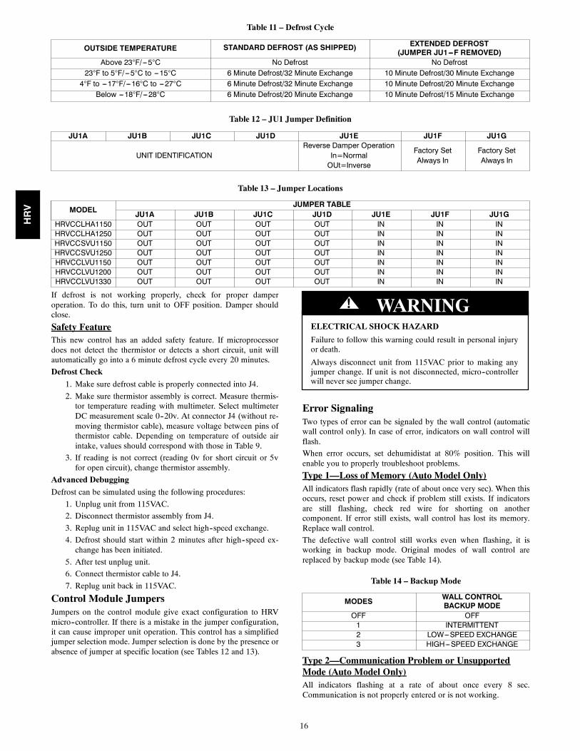
Table 11 – Defrost Cycle
OUTSIDE TEMPERATURE STANDARD DEFROST (AS SHIPPED) EXTENDED DEFROST(JUMPER JU1---F REMOVED)
Above 23°F/---5°C No Defrost No Defrost23°F to 5°F/---5°C to ---15°C 6 Minute Defrost/32 Minute Exchange 10 Minute Defrost/30 Minute Exchange4°F to ---17°F/---16°C to ---27°C 6 Minute Defrost/32 Minute Exchange 10 Minute Defrost/20 Minute Exchange
JU1A JU1B JU1C JU1D JU1E JU1F JU1GHRVCCLHA1150 OUT OUT OUT OUT IN IN INHRVCCLHA1250 OUT OUT OUT OUT IN IN INHRVCCSVU1150 OUT OUT OUT OUT IN IN INHRVCCSVU1250 OUT OUT OUT OUT IN IN INHRVCCLVU1150 OUT OUT OUT OUT IN IN INHRVCCLVU1200 OUT OUT OUT OUT IN IN INHRVCCLVU1330 OUT OUT OUT OUT IN IN IN
If defrost is not working properly, check for proper damperoperation. To do this, turn unit to OFF position. Damper shouldclose.
Safety FeatureThis new control has an added safety feature. If microprocessordoes not detect the thermistor or detects a short circuit, unit willautomatically go into a 6 minute defrost cycle every 20 minutes.
Defrost Check
1. Make sure defrost cable is properly connected into J4.
2. Make sure thermistor assembly is correct. Measure thermis-tor temperature reading with multimeter. Select multimeterDC measurement scale 0--20v. At connector J4 (without re-moving thermistor cable), measure voltage between pins ofthermistor cable. Depending on temperature of outside airintake, values should correspond with those in Table 9.
3. If reading is not correct (reading 0v for short circuit or 5vfor open circuit), change thermistor assembly.
Advanced Debugging
Defrost can be simulated using the following procedures:
1. Unplug unit from 115VAC.
2. Disconnect thermistor assembly from J4.
3. Replug unit in 115VAC and select high--speed exchange.
4. Defrost should start within 2 minutes after high--speed ex-change has been initiated.
5. After test unplug unit.
6. Connect thermistor cable to J4.
7. Replug unit back in 115VAC.
Control Module JumpersJumpers on the control module give exact configuration to HRVmicro--controller. If there is a mistake in the jumper configuration,it can cause improper unit operation. This control has a simplifiedjumper selection mode. Jumper selection is done by the presence orabsence of jumper at specific location (see Tables 12 and 13).
ELECTRICAL SHOCK HAZARD
Failure to follow this warning could result in personal injuryor death.
Always disconnect unit from 115VAC prior to making anyjumper change. If unit is not disconnected, micro--controllerwill never see jumper change.
! WARNING
Error SignalingTwo types of error can be signaled by the wall control (automaticwall control only). In case of error, indicators on wall control willflash.
When error occurs, set dehumidistat at 80% position. This willenable you to properly troubleshoot problems.
Type 1—Loss of Memory (Auto Model Only)All indicators flash rapidly (rate of about once very sec). When thisoccurs, reset power and check if problem still exists. If indicatorsare still flashing, check red wire for shorting on anothercomponent. If error still exists, wall control has lost its memory.Replace wall control.
The defective wall control still works even when flashing, it isworking in backup mode. Original modes of wall control arereplaced by backup mode (see Table 14).
Table 14 – Backup Mode
MODES WALL CONTROLBACKUP MODE
OFF OFF1 INTERMITTENT2 LOW---SPEED EXCHANGE3 HIGH---SPEED EXCHANGE
Type 2—Communication Problem or UnsupportedMode (Auto Model Only)All indicators flashing at a rate of about once every 8 sec.Communication is not properly entered or is not working.
HRV
17
Table 15 – System Wiring Colors and Connections
CONTROL MODULE WALL CONTROL WIRE WALL CONTROLTerminal Block No. Terminal Block Identification Color Terminal No. Terminal Identification
J3---9 B Black J1---4 BJ3---8 G Green J1---3 GJ3---7 R Red J1---2 RJ3---6 Y Yellow J1---4 Y
CASE 1
User changes the mode on wall control and HRV does not respondto command (OFF, LOW, or HIGH speed). Check all wires to wallcontrol particularly red wire (see Table 15).
CASE 2
User changes the mode but, HRV does not respond. All indicatorsflash at a rate of about once every 8 sec. Check all wires to wallcontrol particularly green wire. If problem still exists, test wallcontrol with 5 ft (1.5 m) of wire from HRV. If this works, changewall control module inside HRV.
RESET
To reset HRV, proceed as follows:
1. Unplug HRV from 115VAC.
2. Wait 15 sec.
3. Plug HRV into 115VAC.
HRV
18
These products earned the ENERGY STAR® by meeting strictenergy efficiency guidelines set byNatural Resources Canada andthe US EPA. They meet ENERGYSTAR requirements only whenused in Canada.
S HRVCCLHA1150
S HRVCCLHA1250
S HRVCCLVU1330
Energy Star (Canada)
Copyright 2010 Carrier Corp. S 7310 W. Morris St. S Indianapolis, IN 46231 Printed in U.S.A. Edition Date: 04/10
Manufacturer reserves the right to change, at any time, specifications and designs without notice and without obligations.