Page 1 INSTALLATION INSTRUCTIONS AND OWNER'S MANUAL DO NOT ATTEMPT TO MODIFY OR ALTER THE CONSTRUC- TION OF THE FIREBOX OR ITS COMPONENTS. ANY MODI- FICATION OR ALTERATION OF CONSTRUCTION MAY VOID THE WARRANTY OF THIS FIREBOX. CHILDREN AND ADULTS SHOULD BE ALERTED TO THE HAZARDS OF HIGH SURFACE TEMPERATURE AND SHOULD STAY AWAY TO AVOID BURNS OR CLOTHING IG- NITION. YOUNG CHILDREN SHOULD BE CAREFULLY SUPERVISED WHEN THEY ARE IN THE SAME ROOM AS THE FIREBOX. UNIVERSAL FIREBOX FOR ALL VENT-FREE LOG SETS MODELS VFS32FB0F-4 VFS36FB0F-4 VFS42FB0F-4 GAS-FIRED ANSI Z21.91 Ventless Fireplace Enclosures for Gas Fired Dec- orative Type Unvented Room Heaters — Do not store or use gasoline or other flammable vapors and liquids in the vicinity of this or any other appli- ance. — WHAT TO DO IF YOU SMELL GAS • Do not try to light any appliance. • Do not touch any electrical switch; do not use any phone in your building. • Immediately call your gas supplier from a neigh- bor’s phone. Follow the gas supplier’s instruc- tions. • If you cannot reach your gas supplier, call the fire department. — Installation and service must be performed by a quali- fied installer, service agency or the gas supplier. WARNING: If the information in these instructions are not followed exactly, a fire or explosion may result caus- ing property damage, personal injury or loss of life. EMPIRE EMPIRE Comfort Systems Installer: Leave this manual with the appliance. Consumer: Retain this manual for future reference. FOR USE ONLY WITH A LISTED GAS-FIRED UNVENTED DecoratIve room heater not to exceeD 40,000 BTU/H. DO NOT BUILD A WOOD FIRE. WarnInG: Improper installation, adjustment, alteration, service or maintenance can cause injury or property dam- age. Refer to this manual. For assistance or additional in- formation, consult a qualified installer, service agency or the gas supplier. carefully review the instructions supplied with the decora- tive type unvented room heater for the minimum fireplace size requirement. DO NOT INSTALL A VENT-FREE LOG SET In thIS FIreBox, UNLESS THIS FIREBOX MEETS THE MINIMUM DIMENSIONS REQUIRED FOR THE INSTALLATION.
Transcript
Page 1
INSTALLATION INSTrucTIONS AND OwNer'S MANuAL
DO NOT ATTeMpT TO MODIfy Or ALTer The cONSTruc-TION Of The fIrebOx Or ITS cOMpONeNTS. ANy MODI-fIcATION Or ALTerATION Of cONSTrucTION MAy vOID The wArrANTy Of ThIS fIrebOx.chILDreN AND ADuLTS ShOuLD be ALerTeD TO The hAzArDS Of hIgh SurfAce TeMperATure AND ShOuLD STAy AwAy TO AvOID burNS Or cLOThINg Ig-NITION.yOuNg chILDreN ShOuLD be cArefuLLy SupervISeD wheN They Are IN The SAMe rOOM AS The fIrebOx.
uNIverSAL fIrebOx fOr ALL veNT-free LOg SeTS
MODeLSVFS32FB0F-4 VFS36FB0F-4 VFS42FB0F-4
GAS-FIRED
ANSI z21.91 ventless fireplace enclosures for gas fired Dec-orative Type unvented room heaters
— Donotstoreorusegasolineorotherflammablevaporsand liquids in the vicinity of this or any other appli-ance.
— whAT TO DO If yOu SMeLL gAS • Donottrytolightanyappliance. • Donottouchanyelectricalswitch;donotuseany
wArNINg: If the information in these instructions are notfollowedexactly,afireorexplosionmayresultcaus-ingpropertydamage,personalinjuryorlossoflife.
EMPIREEMPIREComfort Systems
Installer: Leavethismanualwiththeappliance.consumer: retain this manual for future reference.
fOr uSe ONLy wITh A LISTeD gAS-fIreD uNveNTeD DecoratIveroomheaternottoexceeD40,000
bTu/h.
DO NOT buILD A wOOD fIre.
WarnInG: Improper installation, adjustment, alteration,serviceormaintenancecancauseinjuryorpropertydam-age. refer to this manual. for assistance or additional in-formation, consult aqualified installer, serviceagencyorthe gas supplier.
Any safety screen or guard removed for servicing an appliancemustbereplacedpriortooperatingtheap-pliance.Provideadequatecombustionandventilationair.theflowofcombustionandventilationairmUStnotbeobstructed.provide adequate clearance around air openings into thecombustionchamberandadequateaccessibilityclearance for servicing and proper operation. Never obstructthefrontopeningoftheappliance.
this empirecomfort Systems, Inc. firebox and itscomponentshavebeentestedandwilloperatesafelywhen installed in accordancewith this installationmanual. read all instructions before startinginstallation, then follow these instructions carefullyduring installation tomaximize firebox benefit andsafety. report to your dealer any parts damaged in shipment.
parts thereof.- Installation other than as instructed byempire
comfortSystems,Inc.- Installation and/or use of any component part or accessory not approved byempirecomfortSystems, Inc. in combination or assemblywitha empire comfort Systems, Inc. firebox, notwithstandinganyindependenttestinglaboratoryorother third party approval of such component part or accessory.
Instructions to Installer1. installer must leave instruction manual with owner after
installation.2. Installer must have owner fill out and mail warranty card
suppliedwithfirebox.3. installer should show owner how to start and operate log set
thatisinstalledintofirebox.Importantall correspondence should refer to complete Model number, Serial number.notice:Duringinitialfiringofthisfireboxwithalogsetinstalled,itspaint will bake out, and smoke will occur. to prevent triggering of smoke alarms, ventilate the room in which the unit is installed.QualifiedInstallingagencyinstallation and replacement of gas piping, gas utilization equipment or accessories and repair and servicing of equipment shall be performedonlybyaqualifiedagency.Theterm"qualifiedagency"meansanyindividual,firm,corporationorcompanywhicheitherinperson or through a representative is engaged in and is responsible for (a) the installation or replacement of gas piping or (b) the connection, installation, repair or servicing of equipment, who is experienced in such work, familiar with all precautions required
and has complied with all the requirements of the authority having jurisdiction.
State of Massachusetts: the installation must be made by a licensed plumber or gas fitter in the Commonwealth ofMassachusetts. the state of Massachusetts requires that a flexible appliance connector cannot exceed three feet inlength.Sellersofunventedpropaneornaturalgas-firedsupplementalroom heaters shall provide to each purchaser a copy of 527 cMR 30 upon sale of the unit.in the State of Massachusetts, unvented propane and natural gas-firedspaceheatersshallbeprohibitedinbedroomsandbathrooms.
the installation must conform with local codes or, in the absence of local codes, with the national Fuel gas code, anSi Z223.1/nFPa 54.**available from the american national Standards institute, inc., 11 West 42nd St., new York, n.Y. 10036.
IMpOrTANT SAfeTy INfOrMATION
INTrODucTION
28188-1-0711Page 4
Sidewallclearances:Theclearancefromtheinsideofthefireboxto perpendicular combustible side wall should not be less than 6".Unitmayberecessedasshownonlywithaccessorylinerkitinstalled. See figure 1.
Top framing and finishing: combustible framing may rest on top of standoffs.Combustible finishingmaterialsmayextendto the top standoff screws on the front edge of the outer wrap. See figure 2.
ceiling clearances:Theceilingheightshouldnotbelessthan42"from the top of the hood. SeeFigures3aand3b.
Mantel clearances: Ventfreefireboxmodelsmustusethehoodsuppliedwiththefirebox,oroneoftheoptionalhoodkitsavailablefor each model. if a combustible mantel is installed, it must meet the clearance requirements detailed below.
grate clearance: the minimum clearance between the front legs ofthegrateandfrontedgeofthefireboxis2".
Leaveatleast36"clearancefromthefrontofthefirebox.
cLeArANceS
45°6"
3"MAX.
PERPENDICULARSIDE WALL
FRONT FACE (SIDE)
FIREBOX(TOP VIEW)
COMBUSTIBLEMATERIALS ALLOWEDIN SHADED AREAS
WITH ACCESSORY LINER ONLY
MANTEL
STANDARDHOOD
13”
10”
12”MAX
42”MIN.
(CEILING TOTOP OF HOOD)
11 1/2”MIN.
FIREBOXFACE
84”MIN.
(CEILING TO FLOOR)
CEILING
COMBUSTIBLESALLOWED
3/8” COMBUSTIBLECLEARANCE REQUIREDFROM TOP EDGEOF FIREBOX
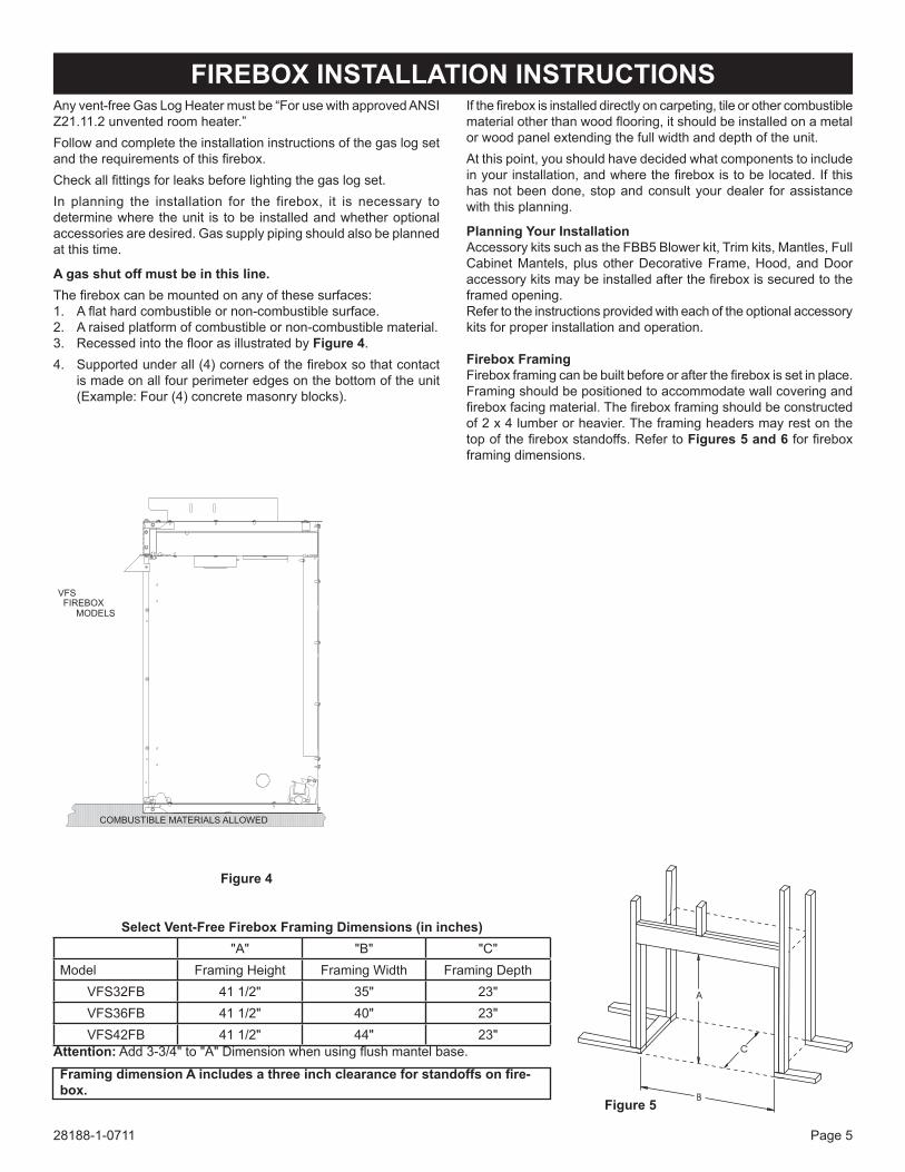
any vent-free gas Log Heater must be “For use with approved anSi Z21.11.2 unvented room heater.”Follow and complete the installation instructions of the gas log set andtherequirementsofthisfirebox.Checkallfittingsforleaksbeforelightingthegaslogset.in planning the installation for the firebox, it is necessary to determine where the unit is to be installed and whether optional accessories are desired. gas supply piping should also be planned at this time.
agasshutoffmustbeinthisline.Thefireboxcanbemountedonanyofthesesurfaces:1. Aflathardcombustibleornon-combustiblesurface.2. a raised platform of combustible or non-combustible material.3. Recessedintothefloorasillustratedby figure 4.4. Supportedunderall(4)cornersofthefireboxsothatcontact
is made on all four perimeter edges on the bottom of the unit (example: Four (4) concrete masonry blocks).
Ifthefireboxisinstalleddirectlyoncarpeting,tileorothercombustiblematerialotherthanwoodflooring,itshouldbeinstalledonametalor wood panel extending the full width and depth of the unit.at this point, you should have decided what components to include inyourinstallation,andwherethefireboxistobelocated.Ifthishas not been done, stop and consult your dealer for assistance with this planning.
planning your Installationaccessory kits such as the FBB5 Blower kit, trim kits, Mantles, Full cabinet Mantels, plus other Decorative Frame, Hood, and Door accessorykitsmaybeinstalledafterthefireboxissecuredtotheframed opening.Refer to the instructions provided with each of the optional accessory kits for proper installation and operation.
FireboxFramingFireboxframingcanbebuiltbeforeorafterthefireboxissetinplace.Framing should be positioned to accommodate wall covering and fireboxfacingmaterial.Thefireboxframingshouldbeconstructedof 2 x 4 lumber or heavier. the framing headers may rest on the topofthefireboxstandoffs.Refertofigures 5 and 6forfireboxframing dimensions.
Ablackhoodthatisfurnishedwitheachfirebox(oroptionalhood)MUSTbeinstalledbeforethefireboxisused.Failuretodosomaycreateapossiblefirehazard.Thehoodislocatedinsidethefireboxonflushfaceunits.Ifbrass,stainlesssteel,orhammeredpewterhoods are desired, they can be purchased as an option. attachment is the same as the standard black hood.
flush face Models
1.Onflushfacemodels,loosenthetwoscrews(A)holdingfireboxtoptofacepanel,thenslidethehoodflangebetweenthefireboxtop and face panel and re-tighten the screws.
2. install one (1) screw at each end of the hood as shown (c).
A C A C
flush face Models
figure 9
FIREBOX OPENING
CHECK TO SEETHAT BOX IS SQUARE
PRIOR TO ATTACHING TOFRAMING
figure 8
FIreBoxInStaLLatIonInStrUctIonS(continued)
INSTALLINg hOOD
28188-1-0711Page 8
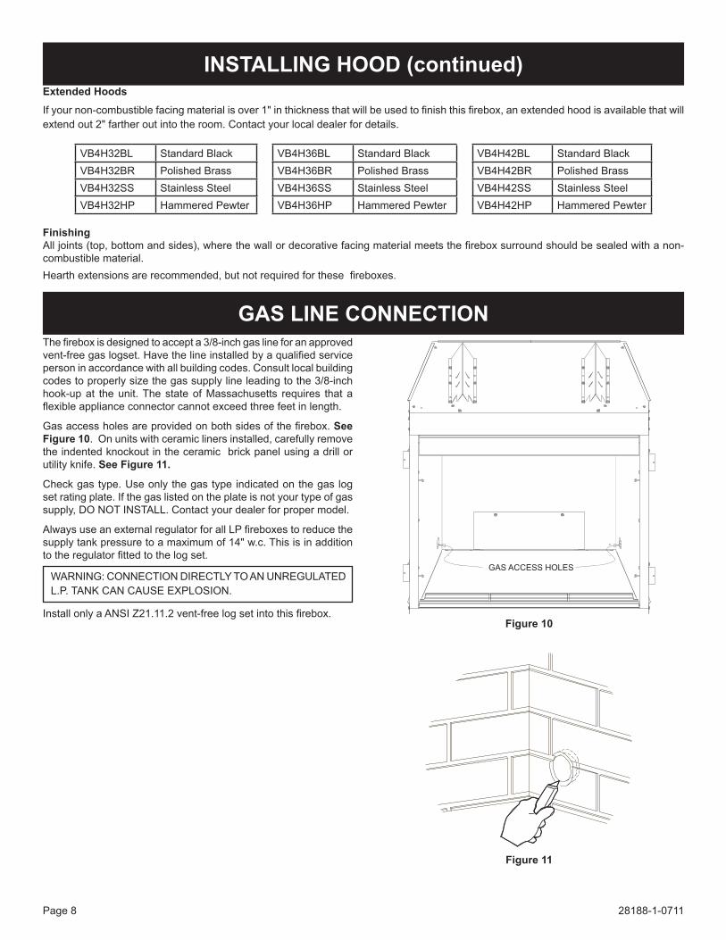
Thefireboxisdesignedtoaccepta3/8-inchgaslineforanapprovedvent-freegaslogset.Havethelineinstalledbyaqualifiedserviceperson in accordance with all building codes. consult local building codes to properly size the gas supply line leading to the 3/8-inch hook-up at the unit. the state of Massachusetts requires that a flexibleapplianceconnectorcannotexceedthreefeetinlength.
Gasaccessholesareprovidedonbothsidesofthefirebox.See figure 10. on units with ceramic liners installed, carefully remove the indented knockout in the ceramic brick panel using a drill or utility knife. See figure 11.
Checkgastype.Useonlythegastypeindicatedonthegaslogset rating plate. if the gas listed on the plate is not your type of gas supply, Do not inStaLL. contact your dealer for proper model.
VB4H32BL Standard Black VB4H36BL Standard Black VB4H42BL Standard BlackVB4H32BR Polished Brass VB4H36BR Polished Brass VB4H42BR Polished BrassVB4H32SS Stainless Steel VB4H36SS Stainless Steel VB4H42SS Stainless SteelVB4H32HP Hammered Pewter VB4H36HP Hammered Pewter VB4H42HP Hammered Pewter
GAS ACCESS HOLES
figure 11
InStaLLInGhooD(continued)
gAS LINe cONNecTION
28188-1-0711 Page 9
REMOVE BLOWER COVERTO GAIN ACCESS FOR BLOWERINSTALLATION.NOTE: IF THE BLOWER CAN BE INSTALLEDPRIOR TO FIREBOX INSTALLATION, IT MAYBE EASIER TO REMOVE THE REAR COVERPLATE PANEL ON THE BACK OF THE FIREBOXRATHER THAN REMOVING BRICK PANELS.
OpTIONAL SINgLe SpeeD bLOwer INSTALLATION INSTrucTIONSAttention: install blower assembly before connecting gas inlet
supply line.
wiringthe appliance, when installed, must be electrically grounded in accordance with local codes or, in the absence of local codes, with the National Electrical Code, ANSI/NFPA 70, if an external electrical source is utilized. this appliance is equipped witha three-prong [grounding] plug for your protection against shockhazardandshouldbepluggeddirectlyintoaproperlygrounded three-prong receptacle. Do not cut or remove the grounding prong from this plug. For an ungrounded receptacle, an adapter, which has two prongs and a wire for grounding, can be purchased, plugged into the ungrounded receptacle and its wire connected to the receptacle mounting screw. With this wire com-pleting the ground, the appliance cord plug can be plugged into the adapter and be electrically grounded.
caution: Label all wires prior to disconnection when servic-ing controls. Wiring errors can cause improper and dangerous operation. Verify proper operation after servicing.
Note: Junctionboxonrightsideoffireboxmustbepre-wiredattimeoffireboxinstallationforusewithblowerassembly.Astandard wall on/oFF wall switch or optional ScV1 Vari-able Speed control Kit should be installed to activate power to the Firebox, and control the operation of the FBB5 Blower assembly. it is recommended that installation of the wiring beperformedbyaqualifiedelectrician.See figure 12.
FieD eLectRician anD SHaLL Be in coMPLiance WitH ALLLOCAL,CITYANDSTATEBUILDINGCODES.BEFOREMAKING THE ELECTRICAL CONNECTION, MAKE SURETHAT MAIN POWER SUPPLY IS DISCONNECTED. THEAPPLIANCE,WHENINSTALLED,MUSTBEELECTRICAL-LYGROUNDEDINACCORDANCEWITHLOCALCODES,WitH tHe nationaL eLectRicaL coDe anSi/nFPa 70 (LateSt eDition).
a factory installed junction box is located on the lower right sideofthefirebox.Wiringmustbefedtothejunctionboxandattached to the receptacle that is provided. From right side of thefirebox, remove thescrewsecuring the junctionboxas-sembly. Leave approximately 6” of wire in the junction box for connection.
attach black wire to one side of the receptacle and white wire to opposite side of receptacle. the ground wire should be at-tached to the green (ground) screw.
install the receptacle into the junction box. attach cover plate.
Attention: if installed, do not damage gas inlet supply line whenblowerassemblyisinsertedintofirebox.Insomecases,removal the gas inlet supply line may be necessary.
figure 12
Select Firebox Models
Figure13
NOTE: BLOWER COVER REMOVEDTO SHOW INSTALLATIONOF BLOWER ACCESSORY
figure 14
28188-1-0711Page 10
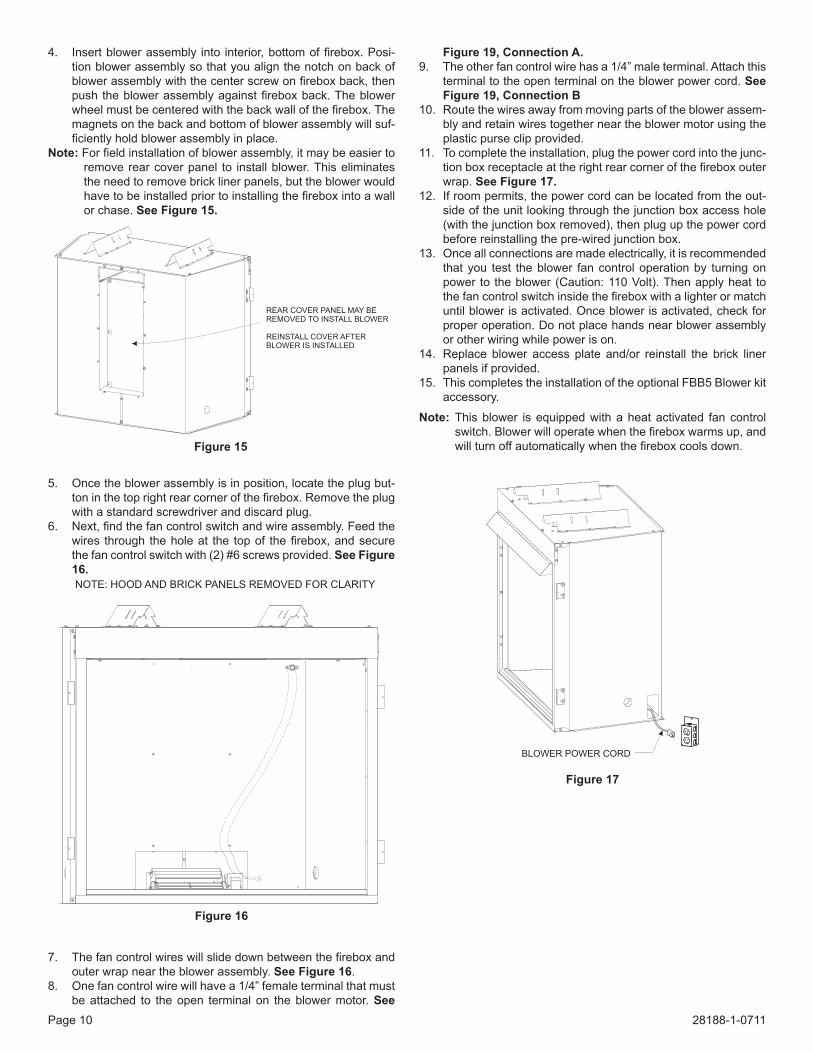
4. Insertblowerassembly into interior,bottomoffirebox.Posi-tion blower assembly so that you align the notch on back of blowerassemblywiththecenterscrewonfireboxback,thenpushtheblowerassemblyagainstfireboxback.Theblowerwheelmustbecenteredwiththebackwallofthefirebox.Themagnets on the back and bottom of blower assembly will suf-ficientlyholdblowerassemblyinplace.
Note: Forfieldinstallationofblowerassembly,itmaybeeasiertoremove rear cover panel to install blower. this eliminates the need to remove brick liner panels, but the blower would havetobeinstalledpriortoinstallingthefireboxintoawallor chase. See figure 15.
5. once the blower assembly is in position, locate the plug but-toninthetoprightrearcornerofthefirebox.Removetheplugwith a standard screwdriver and discard plug.
6. Next,findthefancontrolswitchandwireassembly.Feedthewires through theholeat the topof thefirebox,andsecurethe fan control switch with (2) #6 screws provided. See figure 16.
7. Thefancontrolwireswillslidedownbetweenthefireboxandouter wrap near the blower assembly. See figure 16.
8. one fan control wire will have a 1/4” female terminal that must be attached to the open terminal on the blower motor. See
Figure19,connectiona.9. the other fan control wire has a 1/4” male terminal. attach this
terminal to the open terminal on the blower power cord. See Figure19,connectionB
10. Route the wires away from moving parts of the blower assem-bly and retain wires together near the blower motor using the plastic purse clip provided.
11. to complete the installation, plug the power cord into the junc-tionboxreceptacleattherightrearcornerofthefireboxouterwrap. SeeFigure17.
12. if room permits, the power cord can be located from the out-side of the unit looking through the junction box access hole (with the junction box removed), then plug up the power cord before reinstalling the pre-wired junction box.
13. once all connections are made electrically, it is recommended that you test the blower fan control operation by turning on power to the blower (caution: 110 Volt). then apply heat to thefancontrolswitchinsidethefireboxwithalighterormatchuntil blower is activated. once blower is activated, check for proper operation. Do not place hands near blower assembly or other wiring while power is on.
14. Replace blower access plate and/or reinstall the brick liner panels if provided.
15. this completes the installation of the optional FBB5 Blower kit accessory.
Note: this blower is equipped with a heat activated fan control switch.Blowerwilloperatewhenthefireboxwarmsup,andwillturnoffautomaticallywhenthefireboxcoolsdown.
REAR COVER PANEL MAY BEREMOVED TO INSTALL BLOWER
REINSTALL COVER AFTERBLOWER IS INSTALLED
figure 15
NOTE: HOOD AND BRICK PANELS REMOVED FOR CLARITY
figure 16
Figure17
BLOWER POWER CORD
28188-1-0711 Page 11
Blowermotorthe blower motor does not have oiling holes. Do not attempt to oil the blower motor.
BlowerWheelsthe blower wheels will collect lint and could require periodic clean-ing. if the air output decreases or the noise level increases, it indi-cates a dirty blower wheel. Remove fan and clean blower wheels.
warning:Unpluggingof bloweraccessorywill not stop theheater from cycling. to turn off gas to the heater (millivolt model): push in gas control knob slightly and turn clockwise to “oFF.” Do not force. to turn off gas on direct ignition model, turn gas line valve to “oFF.”
1 FBB5 BLoWeR aSSeMBLY coMPLete2 R9901 Fan contRoL SWitcH
a factory installed junction box is located on the lower right handsideofthefirebox.Wiringmustbefedtothejunctionboxand attached to the receptacle that is provided. Remove the knockout in the installed junction box to accept wiring into the junctionbox.InstallaULlistedcableclamp(notsupplied)intheknockouthole.Leaveapproximately6"ofwireinthejunctionboxfor connection.attach black wire to one side of the receptacle and white wire to opposite side of receptacle. the ground wire should be attached to the green (neutral) screw.install the receptacle into the junction box. attach cover plate.
Keep the control compartment, logs and burner area surrounding the logs clean by vacuuming or brushing area at least twice a year.tHe LogS can get VeRY Hot – HanDLe onLY WHen cooL.always turn off gas to the pilot before cleaning. For relighting, refer to lighting instructions located on the log set.
Neverobstructtheflowofthecombustionandventilationair.Keepthefrontofthefireboxclearofallobstaclesandmaterials.Screens must be closed during operation.
Wall mounted variable speed control for use with FBB5 blower ScV-1
frame Kits
Standard 3-Piece Frame KitsBlack, Brass, Stainless Steel, or Hammered Pewter
extruded aluminum Frame KitsBlack, Brass, Stainless Steel, or Hammered Pewter
contact dealer for all available optional frame kits
Standard hood Brass hood = BR
Stainless Steel = SS
Hammered Pewter = HP
contact dealer for all available optional hood accessories
extended4"hoodsExtendedhoodsthatextendout2"fartherthanthe standard hoods, to accommodate thicker surround materials.
available as optional kits in Black, Brass, Ham-meredPewter,andStainlessSteelfinishes.
contact dealer for all available optional hood accessories
Decorative Door Kits available as optional kits in Black, Brass, Ham-meredPewter,andStainlessSteelfinishes.
contact dealer for all available optional frame kit accessories
Decorative frame Kits available as optional kits in Black, Brass, Ham-meredPewter,andStainlessSteelfinishes.
contact dealer for all available optional decorative door kit
accessories
Accessory Liner Kit Decorative Liner to improve aesthetic appear-anceoffireplacesystem.
contact dealer for all available optional decorative door kit
accessories
28188-1-0711 Page 15
ToOrderPartsUnderWarranty,pleasecontactyour localEmpiredealer.Seethedealer locatoratwww.empirecomfort.com. to provide warranty service, your dealer will need your name and address, purchase date and serial number, and the nature of the problem with the unit. to order Parts after the Warranty Period, please contact your dealer or one of the Master Parts Distributors listed below. this list changes from time to time. For the current list, please click on the Master Parts button at www.empirecomfort.com.Please note: Master Parts Distributors are independent businesses that stock the most commonly ordered original equipment repair parts for Heaters, grills, and Fireplaces manufactured by empire comfort Systems inc.
DeyDistributing1401 Willow Lake BoulevardVadnais Heights, Mn 55101
parts Not under warrantyParts can be ordered through your Service Person, Dealer, or a Master Parts Distributor. See this page for the Master Parts Distribu-tors list. For best results, the service person or dealer should order parts through the distributor. Parts can be shipped directly to the service person/dealer.warranty partsWarranty parts will need a proof of purchase and can be ordered by your Service Person or Dealer. Proof of purchase is required for warranty parts.AllpartslistedinthePartsListhaveaPartNumber.Whenorderingparts,firstobtaintheModelNumberandSerialNumberfromthename plate on your equipment. then determine the Part number (not the index number) and the Description of each part from the fol-lowing illustration and part list. Be sure to give all this information . . .
appliance Model number Part Description
appliance Serial number Part number
type of gas (Propane or natural)
Do not order bolts, screws, washers or nuts. they are standard hardware items and can be purchased at any local hardware store. Shipmentscontingentuponstrikes,firesandallcausesbeyondourcontrol.
hOw TO OrDer repAIr pArTS
28188-1-0711Page 16
EMPIREEMPIREComfort Systems
empire comfort Systems inc.918 Freeburg ave. Belleville, iL 62220
if you have a general question about our products, please e-mail us at [email protected]. if you have a service or repair question, please contact your dealer.