The following installation instructions should be used as a guide for installing Folding Guard Qwik-Fence® Partitions. Good common sense and appropriate safety precautions must be used during installations. The product may be unstable during installation; accordingly - temporary bracing should be implemented until all hardware is tightened and the product is properly anchored to the floor. Permanent field bracing (Not supplied) may be installed at installer’s/owner’s discretion. Installation problems arising from job site conditions should be referred to a professional installer. Refer product assembly questions to Folding Guard®.
Self-Tapping Screw Installation Recommendations:
When installing self-tapping screws use a standard variable speed screw gun equipped with an adjustable clutch or depth locating nosepiece. Take care not to over tighten or strip, set the drill accordingly. DO NOT USE IMPACT TYPE GUN WHEN INSTALLING SELF-TAPPING SCREWS. Securely clamp component parts in place before attaching with self-tapping screws.
Tools Required: 5/16 Socket Drill Bit Attachment 3/8 Masonry Bit 5/16 Masonry Bit 5/16
Wrench 7/16 Wrench 9/16
Wrench Hammer Electric Drill (Var. Speed)
Tools Recommended: Ladder Carpenters Level Chalk Line Heavy Duty Wire cutters
Installer Tips: Installation is best completed with the help of one or two people. Prior to beginning, please read through all instructions pertinent to your installation. (Doors, panels, etc…) Panels are to be installed horizontally between posts, parallel with the ground. Prior to beginning, if at all possible please lay out the parts where they are to be installed. Make sure all posts are installed perpendicular to the floor; shims (NOT SUPPLIED) may be required. Use 2” spacer block (NOT SUPPLIED) to support the panel during the installation. Begin installation at a wall (If your plan calls for a wall connection), corner or an end of a post. Hinge door opening is determined by header bar. Please consult your plan for location and dimensions. Assembly hardware will be installed on the inside of most systems. Installer should eliminate any bolts or hardware protruding into aisle ways or around door openings.
Prior to Installation:
Prior to beginning installation please make sure that you have all the parts required for the assembly
Make sure that the installation area is clear of all obstructions.
Read thoroughly all the instruc-tions pertinent to your installation.
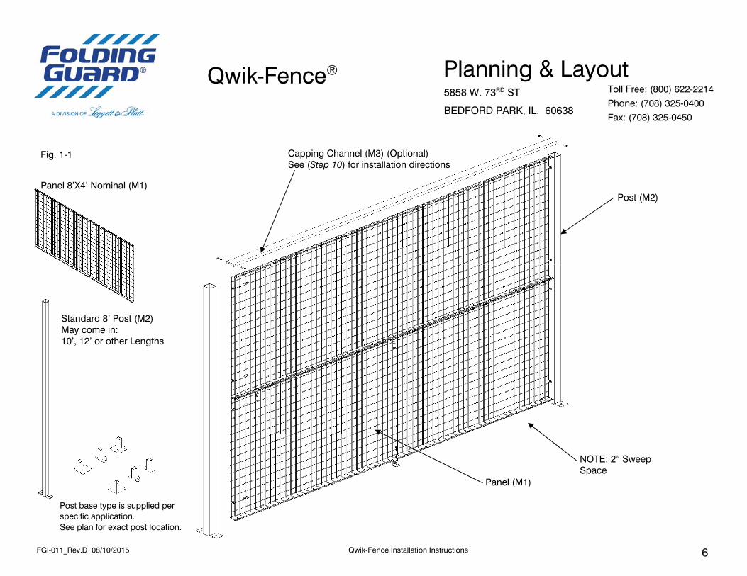
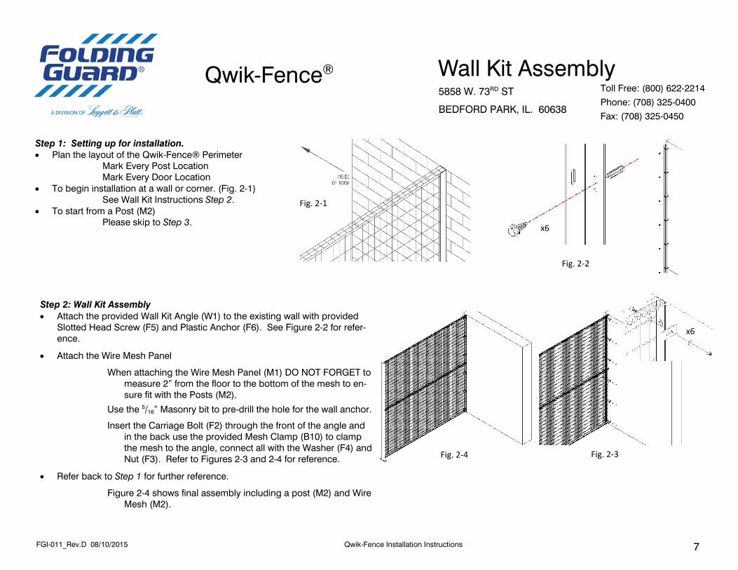
Step 1: Setting up for installation. Plan the layout of the Qwik-Fence® Perimeter
Mark Every Post Location Mark Every Door Location
To begin installation at a wall or corner. (Fig. 2-1) See Wall Kit Instructions Step 2.
To start from a Post (M2) Please skip to Step 3.
Fig. 2‐2
Step 2: Wall Kit Assembly Attach the provided Wall Kit Angle (W1) to the existing wall with provided
Slotted Head Screw (F5) and Plastic Anchor (F6). See Figure 2-2 for refer-ence.
Attach the Wire Mesh Panel
When attaching the Wire Mesh Panel (M1) DO NOT FORGET to measure 2” from the floor to the bottom of the mesh to en-sure fit with the Posts (M2).
Use the 5/16” Masonry bit to pre-drill the hole for the wall anchor.
Insert the Carriage Bolt (F2) through the front of the angle and in the back use the provided Mesh Clamp (B10) to clamp the mesh to the angle, connect all with the Washer (F4) and Nut (F3). Refer to Figures 2-3 and 2-4 for reference.
Refer back to Step 1 for further reference.
Figure 2-4 shows final assembly including a post (M2) and Wire Mesh (M2).
Space off the Post (M2) to be flush with the end of the currently attached panel(s) (M1).
Reference Distances are as follows:
Wall to center of First post: 95” Center of Post to Center of Post: 96”
Secure the post to the floor using floor anchors (Not Supplied) Recommended: ½”DIA X 3.75”L Anchor
You may use holes in the posts (M1) as a drill guide. Refer to Figure (3-2) for reference. Use Figure (3-1) for post orientation.
Fig. 3‐1
Inside of Room
Step 4: Adding a Panel (M1).
Place the panel so that the flanges of panel are facing towards the inside of the room. (DO NOT ghten as that is the last step). See Figure (3‐1) for reference.
The lower panel should be approximately (two) 2” off the ground (for Standard Installa on). If you have a ver cal post (M2) with a 2”X6” base you may use that post as a spacer by laying that post (M2) on its side.
Insert a Panel Clip bracket (B1) around the end wire of the panel (M1) at the corresponding predrilled hole of the post (M2). Refer to Figure (5‐1) for reference. Repeat for all the predrilled holes (3/Panel). Fig. 3‐2
Step 5: Adding Top Panel (M1) Vertically.
Insert a Panel Clip bracket (B1) around the end wire of the panel (M1) at the corresponding predrilled
hole of the post (M2). Refer to Figure (5-1) for reference. Repeat for all the predrilled holes. Approximately 2 Panel Clip brackets (B1) per 4’H Panel (M1)
Using the provided Carriage Bolt (F2), Hex Nut (F3), Washer (F4) secure the two panels together
equally spaced for (three) 3 locations of bolts. Refer to Figure (5-1) for reference. Spaced equally through out the Panel (M1) span.
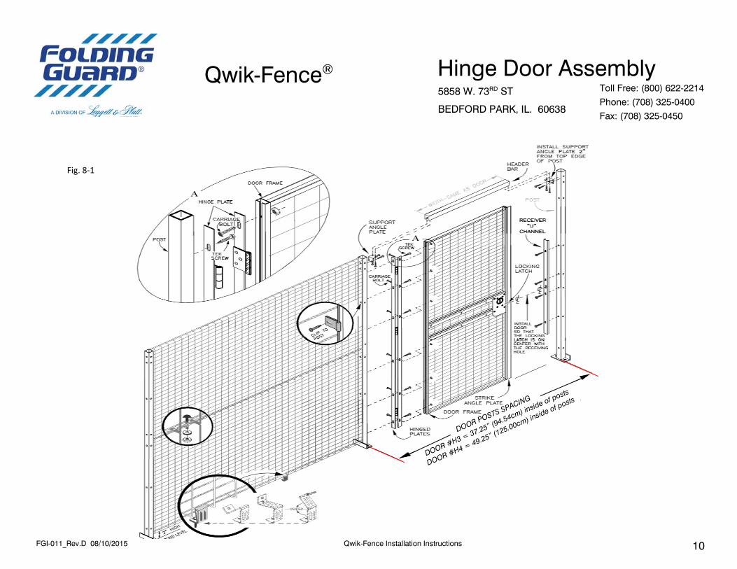
Step 8: Installing Hinge Door (Optional) Prior to beginning installation make sure that your plan includes a door and that it is a Hinge door. Prior to beginning installation make sure that the door is manufactured per your requirements and matches the overall plan layout in terms of hinge and lock.
Prior to beginning make sure that all the parts required for a Hinge door assembly are included. Prior to beginning make sure that your side posts are already installed and are secure in their location. The spacing for the Hinge doors are as follows:
H3 – 37.5” X 96” (From the ground to the top of the clearance for the door) 37.5” header width. H4 – 49.5” X 96” (From the ground to the top of the clearance for the door) 49.5” header width.
Refer to Figure (8-2) for reference. Refer to Figure (8-1) for overall instructions.
Step 8A: Installing Header Bar (D4)
Place the Header bar (D4) at approximately 94” from the floor to the bottom of header bar (D4), and even with the top of the Posts (M2).
Refer to Figure (8A-1) for reference. Attach it to the vertical post with the Hinge Door Bracket (B3)
Secure with the Self Tapping Screw (F1) as shown.
Refer to Figure (8A-1) for location of clips. Refer to Figure (8A-2) for assembly instructions.
Fig. 8A‐1
Step 8B: Determining the Door Hinge Direction. The included Hinge door can be attached 1 of 4 ways. See Figure (8B-1) If your door swings IN please refer to (Step 8F). If your door swings OUT please refer to (Step 8D).
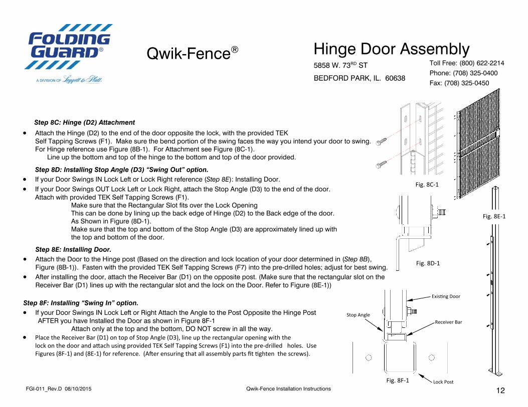
Step 8C: Hinge (D2) Attachment Attach the Hinge (D2) to the end of the door opposite the lock, with the provided TEK Self Tapping Screws (F1). Make sure the bend portion of the swing faces the way you intend your door to swing. For Hinge reference use Figure (8B-1). For Attachment see Figure (8C-1). Line up the bottom and top of the hinge to the bottom and top of the door provided.
Step 8D: Installing Stop Angle (D3) “Swing Out” option. If your Door Swings IN Lock Left or Lock Right reference (Step 8E): Installing Door. If your Door Swings OUT Lock Left or Lock Right, attach the Stop Angle (D3) to the end of the door. Attach with provided TEK Self Tapping Screws (F1).
Make sure that the Rectangular Slot fits over the Lock Opening This can be done by lining up the back edge of Hinge (D2) to the Back edge of the door. As Shown in Figure (8D-1). Make sure that the top and bottom of the Stop Angle (D3) are approximately lined up with the top and bottom of the door.
Fig. 8E‐1
Step 8E: Installing Door. Attach the Door to the Hinge post (Based on the direction and lock location of your door determined in (Step 8B), Figure (8B-1)). Fasten with the provided TEK Self Tapping Screws (F7) into the pre-drilled holes; adjust for best swing. After installing the door, attach the Receiver Bar (D1) on the opposite post. (Make sure that the rectangular slot on the Receiver Bar (D1) lines up with the rectangular slot and the lock on the Door. Refer to Figure (8E-1))
Fig. 8D‐1
Fig. 8F‐1
Stop Angle
Exis ng Door
Receiver Bar
Lock Post
Step 8F: Installing “Swing In” option. If your Door Swings IN Lock Left or Right Attach the Angle to the Post Opposite the Hinge Post AFTER you have Installed the Door as shown in Figure 8F-1 Attach only at the top and the bottom, DO NOT screw in all the way. Place the Receiver Bar (D1) on top of Stop Angle (D3), line up the rectangular opening with the lock on the door and a ach using provided TEK Self Tapping Screws (F1) into the pre‐drilled holes. Use Figures (8F‐1) and (8E‐1) for reference. (A er ensuring that all assembly parts fit ghten the screws).
Step 9: Installing a Slide Door (Optional) Prior to beginning installation of slide door make sure that your layout includes an appropriate side slide door. Prior to beginning make sure that all the parts required for a slide door assembly are included (see below). Prior to beginning make sure that your side posts are already installed and are secure in their location. The spacing for the slide doors are as follows:
96”
S5
S8
S4
S7
S6
S3
S3 – 36” X 96” (From the ground to the top of the clearance for the door)
S4 – 48” X 96” (From the ground to the top of the clearance for the door)
S5 – 60” X 96” (From the ground to the top of the clearance for the door)
S6 – 72” X 96” (From the ground to the top of the clearance for the door)
S7 – 84” X 96” (From the ground to the top of the clearance for the door)
S8 – 96” X 96” (From the ground to the top of the clearance for the door)
Refer to Figure (9-2) for reference. Refer to Figure (9-1) for overall reference.
Step 9A: Slide Door Bracket (B4) Assembly.
If your Post (M2) Height is MORE then 96” proceed to (Step 9C).
Assemble Slide Door Bracket (B4) and Slide Door Mounting Strip (B5) with an (F10), (F7) and
(F3) as shown in Figure (9A-1). Please note that Mounting Strip (B5) has uneven placed holes make sure to attach the Bracket (B4) to the farthest hole.
Step 9B: Slide Door Pre-Assembly. Attach the Guide (B8) to the bottom back end of the door with provided Carriage Bolt (F2) and Nut (F3), as shown in Figure (9B-1). Attach the Trolley assembly (B9) to the top of the door by inserting it into the existing holes at the top of the door. For reference use Figure (9B-2).
Fig. 9B‐2 Fig. 9B‐1
Step 9C: Slide Channel Assembly & A achment. Take the slide door bracket assembly (Step 9A) and a ach it through the bo om two holes via a TEK Screw (F1) and a Washer (F4). Refer to Figure (9C‐1) for visual instruc ons. Insert the Slide Door Track inside the Slide Door Bracket Assembly as shown in Figure 9D‐2. Tighten the bolts on top of the Slide Door Bracket (B4) through the holes in the Slide Door Track (D6). Refer to Figure (9C‐2) for Visual Instruc ons. (NOTE: The holes DO NOT have to be aligned, however make sure the gap between channels is minimal)
If your Ver cal Post height is taller then 96” DO NOT a ach the Slide Door Bracket (B4) to the Slide Door Moun ng Strip (B5). Instead Measure 96” from the ground to the bo om of the Slide Door Bracket (B4) and using a TEK screw (F1) and (F4) washer a ach directly to post.
Fig. 9C‐2 Fig. 9C‐1
Fig. 9D‐1
Step 9D: Slide Door Assembly. Take the Assembled door (Step 9C) and insert the trolleys into the Slide Door Track (D6). See Figure 9D‐1 for reference. Slide the door all the way through. Make sure that that door moves freely with in the Slide Door Track (D6). Make sure there is a 2” clearance between the bo om of the door and the floor. If there is not adjust the trolleys un l there is. Please note that when inser ng the door assembly the front of the door should go in first and that the lock should be facing towards the direc ons that is specified in the Plan Drawings either provided by Folding Guard® or Your Company’s Representa ve. A er Inser ng the Door, please insert the Stop Bolt (F12) into the free hole in the Slide Door Track Assembly on the back end of the door, and Tighten with Nut (F3). This will prevent the door from sliding out of the Slide Door Track (D6). CAUTION: Door Stop Bolt must be installed in order to prevent the door from exi ng the track.
A ach the supplied Lock Receiver Bar (D5) to the post toward which the door shall close, with the provided TEK Screw (F1). See Figures (9E‐1) and (9E‐2) for reference. DO NOT Tighten the TEK (F1) Screws all the way. First make sure the door securely locks in the receiver bar and can be opened. A er that is complete Tighten the TEK Screws (F1) all the way. Please note that the Figure (9E‐1) is the LOCKED and FINISHED condi on of the Lock Receiver Bar (D5) and the door.
Step 9F: Bo om Guide (B6) Assembly.
Assemble the two halves of the bo om guide (B6) by placing one half inside of the other as shown in Figure (9F‐1). Secure the two halves together. If you intend to a ach the guide (B6) to the wire mesh panel (M1). Please go on the next point. If you intend to secure the Guide (B6) to the floor, secure together via floor anchors as shown in Figure (9F‐2)
If a aching the Bo om guide to the wire mesh assemble the two halves of the Bo om Guide (B6) and secure together with a Carriage Bolt (F2), Washer (F4) and a Nut (F3), as shown in Figure 9F‐3.
Step 9G: Bo om Guide Installa on.
If a aching to the floor – place the bo om guide in such a ma er that when the door is closed the Door Guide (B8) is s ll inside the Bo om Guide Bracket (B6). Make sure that the door slides easily inside the floor bracket (B6) and there is no interference. Then a ach to the floor via concrete anchors.
If a aching to the wire mesh ‐ place the bo om guide in such a ma er that when the door is closed the Door Guide (B7) is s ll inside the Bo om Guide Bracket (B6). Make sure that the door slides easily inside the floor bracket (B6) and there is no interference. Then using the provided Bo om Guide A achment (B7). Secure both via provided Carriage Bolt (F2), Washer (F4) and Nut (F3), as shown in Figure (9G‐1).