Step-by-step instructions for installing the best in supercharger systems. Installation Instructions for: INTERCOOLED SUPERCHARGER SYSTEM 2009-10 Dodge Challenger 5.7 Liter HEMI 89-89-61-060 Rev I 89-89-61-060 Rev I * PREMIUM GASOLINE FUEL REQUIRED * * PREMIUM GASOLINE FUEL REQUIRED * ATTENTION! Your MAGNUSON SUPERCHARGER kit is sensitive to corrosion! Use only the vehicle manufacturer recommended coolant for your engine in the intercooler system as well. Magnuson Products LLC 1990 Knoll Drive, Bldg A, Ventura, CA. 93003 (805) 642-8833 * (805) 677-4897 fax magnusonsuperchargers.com
Transcript
Step-by-step instructions for installing the best in supercharger systems.
Installation Instructions for:
INTERCOOLED SUPERCHARGER SYSTEM 2009-10 Dodge Challenger 5.7 Liter HEMI
Please take a few moments to review this manual thoroughly before you begin work: Make a quick parts check to make certain your kit is complete (see shipper parts list in this package). If you discover shipping damage or shortage, please call our offi ce immediately. Take a look at exactly what you are going to need in terms of tools, time, and experience. Review our limited warranty with care. When unpacking the supercharger kit DO NOT lift the supercharger assembly by the black plastic bypass actuator. This is pre-set from the factory and can be altered if used as a lifting point!
Caution: Relieve the fuel system pressure before servicing fuel system components in order to reduce the risk of fi re and personal injury. After relieving the system pressure, a small amount of fuel may be released when servicing the fuel lines or connections. In order to reduce the risk of personal injury, cover the regulator and fuel line fi ttings with a shop towel before disconnecting. This will catch any fuel that may leak out. Place the towel in an approved container when the job is complete.
Use only premium gasoline fuel, 91 octane better.Use only premium gasoline fuel, 91 octane better.Magnuson Products supercharger systems are manufactured to produce about 20 RWHP per pound of boost at sea level. High altitudes will produce different numbers.
Our Magnuson Supercharger kits are designed for engines in good mechanical condition only. Installation on high mileage or damaged engines is not recommended and may result in engine failure, for which we are not responsible. Magnuson Products LLC is not responsible for the engine or consequential damages.
Magnuson Products supercharger kits are designed for use on stock vehicles. To that end, the alteration or Magnuson Products supercharger kits are designed for use on stock vehicles. To that end, the alteration or modifi cation of the fuel system, drive train, engine, and/or supercharger outside of stock parameters in any modifi cation of the fuel system, drive train, engine, and/or supercharger outside of stock parameters in any way can result in engine damage or failure for which Magnuson Products is NOT responsible and will void way can result in engine damage or failure for which Magnuson Products is NOT responsible and will void Magnuson Products warranty and CARB certifi cation. Aftermarket engine recalibration devices that modify Magnuson Products warranty and CARB certifi cation. Aftermarket engine recalibration devices that modify fuel and spark curve (including, but not limited to programmers) are not recommended and may cause fuel and spark curve (including, but not limited to programmers) are not recommended and may cause engine damage or failure. Use of non-Magnuson Products approved programming will void all warranties. If engine damage or failure. Use of non-Magnuson Products approved programming will void all warranties. If you have any questions, call us.you have any questions, call us.
After you fi nish your installation and road test your vehicle, please fi ll out and mail in the limited warranty card, so we can add you to our fi les (this is important for your protection).
A new fuel fi lter is recommended at the time of supercharger installation Stock spark plugs and stock plug gap is recommended Drive belt = Gates # K060994Tools Required: Metric wrench set ¼” - 3/8” and ½” drive metric socket set (Standard & Deep) 3/8”and ½” drive Foot pound and inch pound torque wrenches Phillips and fl at head screwdrivers Fuel line quick disconnect tools (included in kit) Small or angled 3/8” drill motor Drain pan Hose cutters Hose clamp pliers Safety glasses Metric Allen socket set 3/8” drive Shop vacuum cleaner Blue Loctite Right Angle drill for pinning crank pulley. Helpful Tool: Air or electric impact wrench.
Contact information:Magnuson Products LLCMagna Charger Division1990 Knoll Drive, Bldg AVentura, CA 93003Sales/Tech support 805-289-0044Websites:www.magnusonproducts.comwww.magnacharger.comEmail:[email protected]
1. 1. The fi rst step is to use the provided The fi rst step is to use the provided DiabloSport Trinity hand held tuner to setup DiabloSport Trinity hand held tuner to setup the calibration for your new supercharger the calibration for your new supercharger system. Follow the instructions in the system. Follow the instructions in the supplied DiabloSport tuner manual. Locate supplied DiabloSport tuner manual. Locate your EO sticker and follow the instructions your EO sticker and follow the instructions for placing the sticker on the supercharger. for placing the sticker on the supercharger. NOTE: For now, the customer will have to NOTE: For now, the customer will have to read the stock fi le from the vehicle using the read the stock fi le from the vehicle using the tool, and must email the fi le to calibration. tool, and must email the fi le to calibration. Here the fi le will be modifi ed and emailed Here the fi le will be modifi ed and emailed back to the customer for install in the car.back to the customer for install in the car.
3. 3. Your system requires the use of a Your system requires the use of a minimum 91 Octane gasoline fuel. This minimum 91 Octane gasoline fuel. This system is not compatible with E85 fuel.system is not compatible with E85 fuel.
4. In the trunk of the vehicle, below the lift up panel is the vehicle battery. Disconnect the battery negative (-) cable at the terminal using a 10mm wrench and set it aside where it will not accidentally make connection with the battery post.
2. 2. Your Intercooler system is sensitive Your Intercooler system is sensitive to corrosion. It’s very important to use the to corrosion. It’s very important to use the OEM recommended coolant mixture in your OEM recommended coolant mixture in your supercharger system as well. supercharger system as well.
2009-10 Dodge Challenger 5.7L Hemi
01/16 Page 3 www.magnusonsuperchargers.com
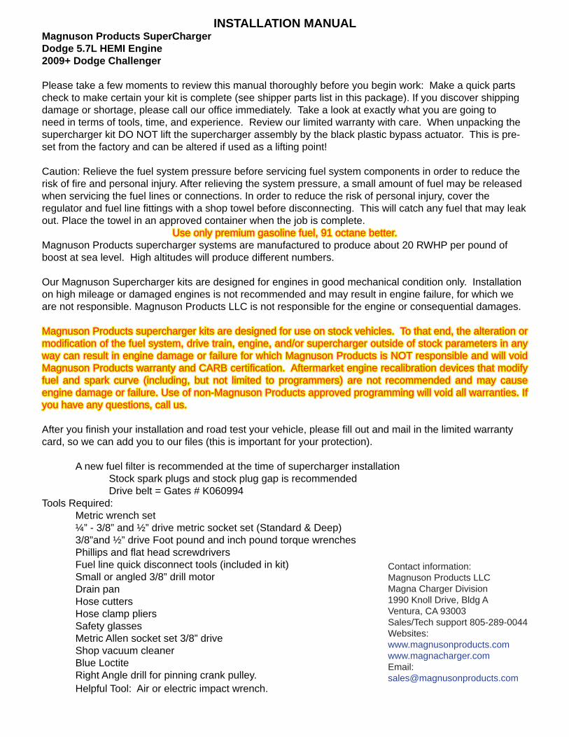
5. Slowly remove the gas cap to release fuel system pressure.
6. Remove the splash shields below and behind the nose fascia. There are two main components, with nine plastic push pin rivets, four 10mm bolts, and seven 7mm bolts holding these components to each other and the framework. Start by removing the push pin rivets by prying out on the center spreader and then pull the rivets free. Now remove the two 10mm bolts joining the two main components together. Next remove the two rear 10mm bolts from the back splash shield.
7. Pull the rear splash shield out of the vehicle and set aside for later re-installation.
8. Remove the seven 7mm bolts from the front of the splash shield where it joins the spoiler.
2009-10 Dodge Challenger 5.7L Hemi
01/16 Page 4 www.magnusonsuperchargers.com
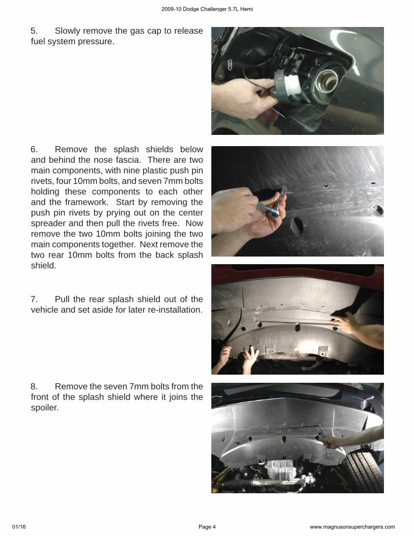
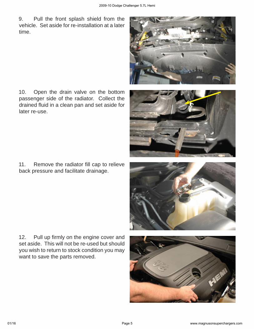
9. Pull the front splash shield from the vehicle. Set aside for re-installation at a later time.
10. Open the drain valve on the bottom passenger side of the radiator. Collect the drained fl uid in a clean pan and set aside for later re-use.
11. Remove the radiator fi ll cap to relieve back pressure and facilitate drainage.
12. Pull up fi rmly on the engine cover and set aside. This will not be re-used but should you wish to return to stock condition you may want to save the parts removed.
2009-10 Dodge Challenger 5.7L Hemi
01/16 Page 5 www.magnusonsuperchargers.com
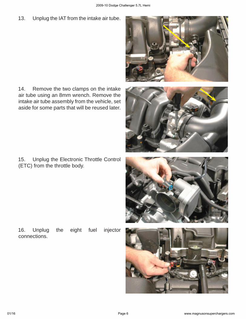
13. Unplug the IAT from the intake air tube.
14. Remove the two clamps on the intake air tube using an 8mm wrench. Remove the intake air tube assembly from the vehicle, set aside for some parts that will be reused later.
15. Unplug the Electronic Throttle Control (ETC) from the throttle body.
16. Unplug the eight fuel injector connections.
2009-10 Dodge Challenger 5.7L Hemi
01/16 Page 6 www.magnusonsuperchargers.com
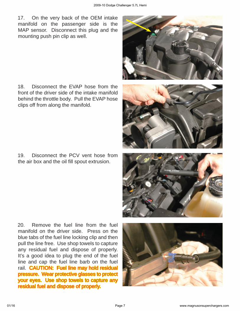
17. On the very back of the OEM intake manifold on the passenger side is the MAP sensor. Disconnect this plug and the mounting push pin clip as well.
18. Disconnect the EVAP hose from the front of the driver side of the intake manifold behind the throttle body. Pull the EVAP hose clips off from along the manifold.
19. Disconnect the PCV vent hose from the air box and the oil fi ll spout extrusion.
20. Remove the fuel line from the fuel manifold on the driver side. Press on the blue tabs of the fuel line locking clip and then pull the line free. Use shop towels to capture any residual fuel and dispose of properly. It’s a good idea to plug the end of the fuel line and cap the fuel line barb on the fuel rail. CAUTION: Fuel line may hold residual CAUTION: Fuel line may hold residual pressure. Wear protective glasses to protect pressure. Wear protective glasses to protect your eyes. Use shop towels to capture any your eyes. Use shop towels to capture any residual fuel and dispose of properly.residual fuel and dispose of properly.
2009-10 Dodge Challenger 5.7L Hemi
01/16 Page 7 www.magnusonsuperchargers.com
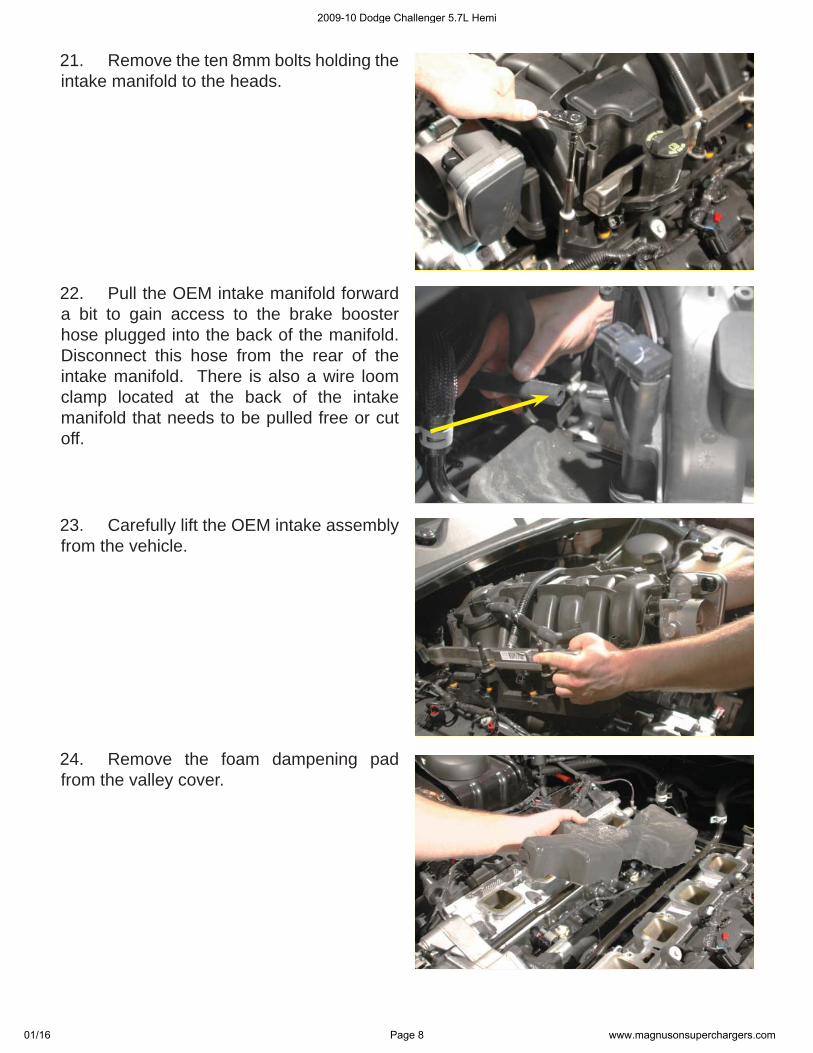
21. Remove the ten 8mm bolts holding the intake manifold to the heads.
22. Pull the OEM intake manifold forward a bit to gain access to the brake booster hose plugged into the back of the manifold. Disconnect this hose from the rear of the intake manifold. There is also a wire loom clamp located at the back of the intake manifold that needs to be pulled free or cut off.
23. Carefully lift the OEM intake assembly from the vehicle.
24. Remove the foam dampening pad from the valley cover.
2009-10 Dodge Challenger 5.7L Hemi
01/16 Page 8 www.magnusonsuperchargers.com
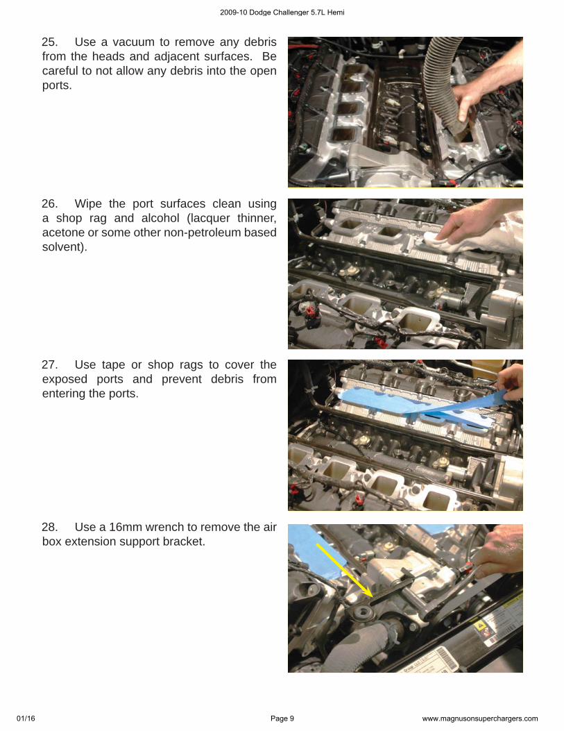
25. Use a vacuum to remove any debris from the heads and adjacent surfaces. Be careful to not allow any debris into the open ports.
26. Wipe the port surfaces clean using a shop rag and alcohol (lacquer thinner, acetone or some other non-petroleum based solvent).
27. Use tape or shop rags to cover the exposed ports and prevent debris from entering the ports.
28. Use a 16mm wrench to remove the air box extension support bracket.
2009-10 Dodge Challenger 5.7L Hemi
01/16 Page 9 www.magnusonsuperchargers.com
29. Remove the two heater hose clamps from the hard line tubes running forward to the water pump.
30. Disconnect the two heater hoses from the hard line connection at the rear of the engine by releasing the clamps and pulling the lines free from the hard line barbs.
31. Remove the 10mm nut holding the ground sensor to the driver side heater hard line mounting bracket stud at the rear of the head.
32. Remove the 10mm nut-stud extension mounting the driver side hard line bracket to the head.
2009-10 Dodge Challenger 5.7L Hemi
01/16 Page 10 www.magnusonsuperchargers.com
33. Temporarily unplug the temperature sensor plug near the water pump.
34. Use a 10mm wrench to remove the hard line mounting bolt from the water pump location.
35. Use a large fl athead and carefully lever the driver side hard line from the water pump using the water pump as a fulcrum.
36. Remove the driver side heater hard line from the engine. There will likely be some fl uid inside the tube, so use care to not throw the fl uid around your work environment, this tube will not be re-used.
2009-10 Dodge Challenger 5.7L Hemi
01/16 Page 11 www.magnusonsuperchargers.com
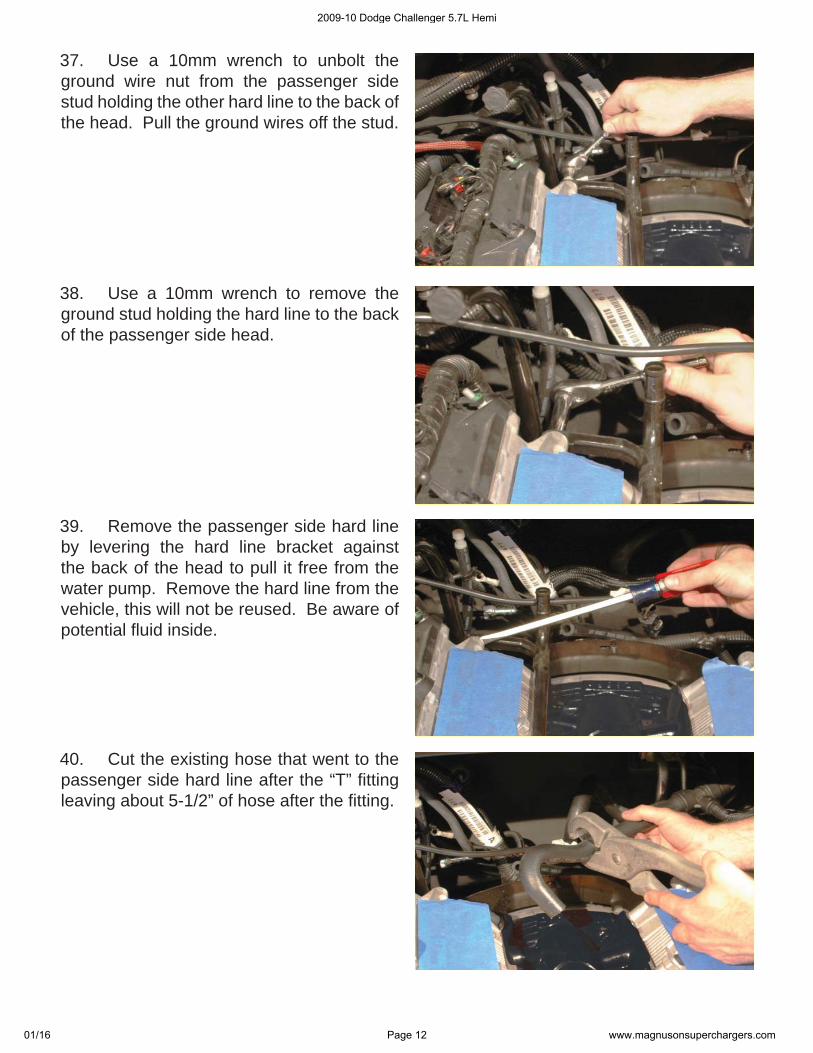
37. Use a 10mm wrench to unbolt the ground wire nut from the passenger side stud holding the other hard line to the back of the head. Pull the ground wires off the stud.
38. Use a 10mm wrench to remove the ground stud holding the hard line to the back of the passenger side head.
39. Remove the passenger side hard line by levering the hard line bracket against the back of the head to pull it free from the water pump. Remove the hard line from the vehicle, this will not be reused. Be aware of potential fl uid inside.
40. Cut the existing hose that went to the passenger side hard line after the “T” fi tting leaving about 5-1/2” of hose after the fi tting.
2009-10 Dodge Challenger 5.7L Hemi
01/16 Page 12 www.magnusonsuperchargers.com
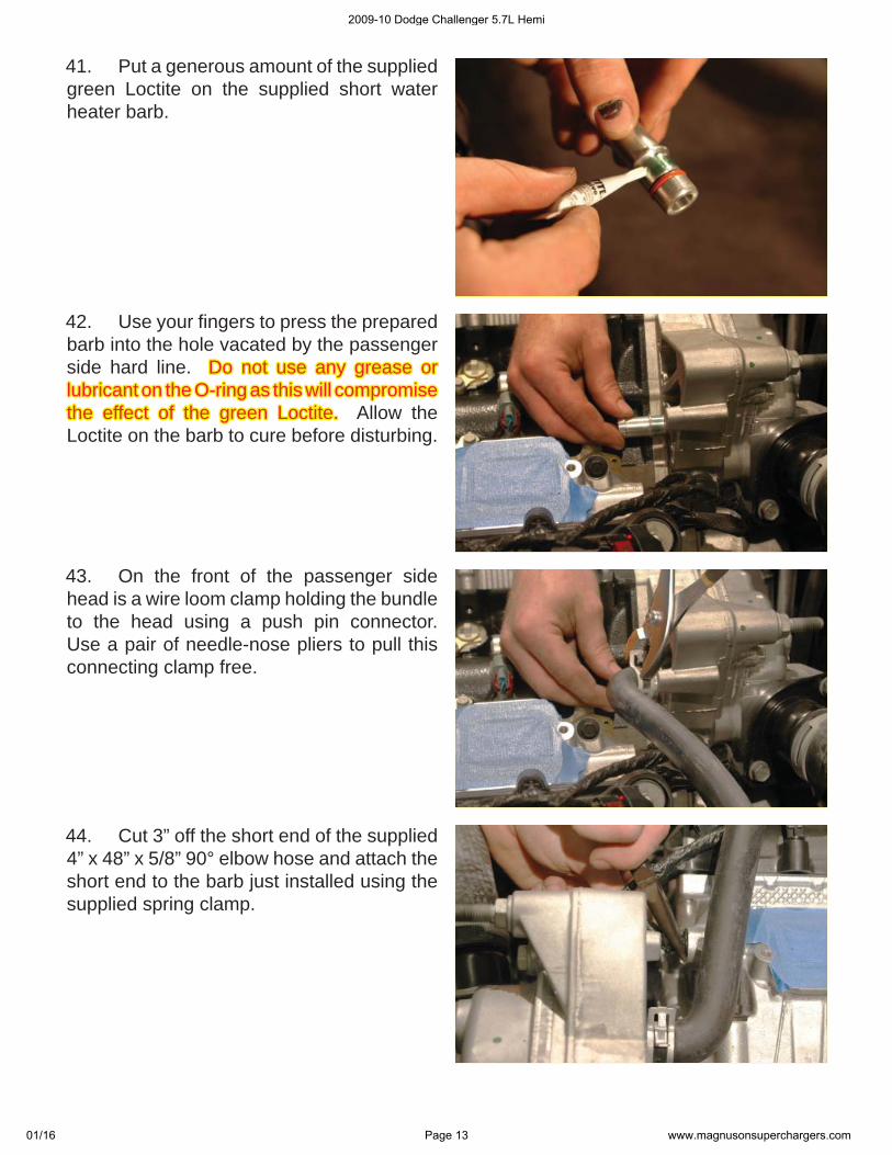
41. Put a generous amount of the supplied green Loctite on the supplied short water heater barb.
42. Use your fi ngers to press the prepared barb into the hole vacated by the passenger side hard line. Do not use any grease or Do not use any grease or lubricant on the O-ring as this will compromise lubricant on the O-ring as this will compromise the effect of the green Loctite. the effect of the green Loctite. Allow the Loctite on the barb to cure before disturbing.
43. On the front of the passenger side head is a wire loom clamp holding the bundle to the head using a push pin connector. Use a pair of needle-nose pliers to pull this connecting clamp free.
44. Cut 3” off the short end of the supplied 4” x 48” x 5/8” 90° elbow hose and attach the short end to the barb just installed using the supplied spring clamp.
2009-10 Dodge Challenger 5.7L Hemi
01/16 Page 13 www.magnusonsuperchargers.com
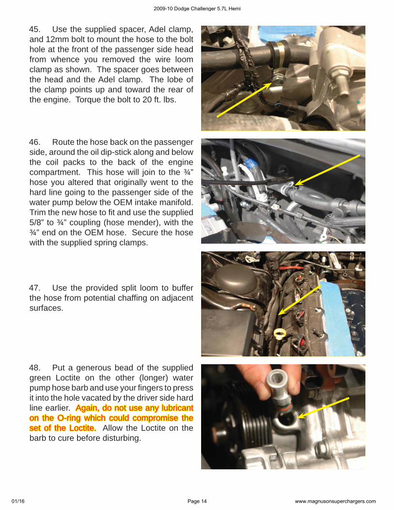
45. Use the supplied spacer, Adel clamp, and 12mm bolt to mount the hose to the bolt hole at the front of the passenger side head from whence you removed the wire loom clamp as shown. The spacer goes between the head and the Adel clamp. The lobe of the clamp points up and toward the rear of the engine. Torque the bolt to 20 ft. lbs.
46. Route the hose back on the passenger side, around the oil dip-stick along and below the coil packs to the back of the engine compartment. This hose will join to the ¾” hose you altered that originally went to the hard line going to the passenger side of the water pump below the OEM intake manifold. Trim the new hose to fi t and use the supplied 5/8” to ¾” coupling (hose mender), with the ¾” end on the OEM hose. Secure the hose with the supplied spring clamps.
47. Use the provided split loom to buffer the hose from potential chaffi ng on adjacent surfaces.
48. Put a generous bead of the supplied green Loctite on the other (longer) water pump hose barb and use your fi ngers to press it into the hole vacated by the driver side hard line earlier. Again, do not use any lubricant Again, do not use any lubricant on the O-ring which could compromise the on the O-ring which could compromise the set of the Loctite.set of the Loctite. Allow the Loctite on the barb to cure before disturbing.
2009-10 Dodge Challenger 5.7L Hemi
01/16 Page 14 www.magnusonsuperchargers.com
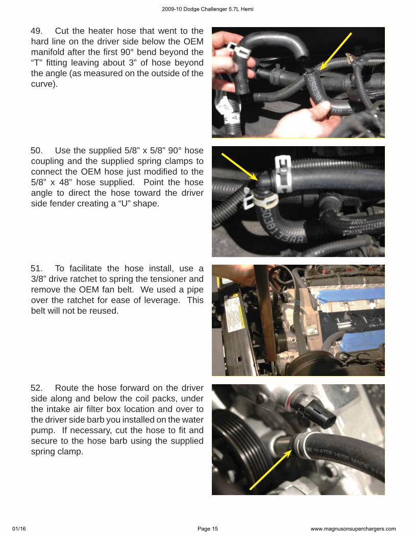
49. Cut the heater hose that went to the hard line on the driver side below the OEM manifold after the fi rst 90° bend beyond the “T” fi tting leaving about 3” of hose beyond the angle (as measured on the outside of the curve).
50. Use the supplied 5/8” x 5/8” 90° hose coupling and the supplied spring clamps to connect the OEM hose just modifi ed to the 5/8” x 48” hose supplied. Point the hose angle to direct the hose toward the driver side fender creating a “U” shape.
51. To facilitate the hose install, use a 3/8” drive ratchet to spring the tensioner and remove the OEM fan belt. We used a pipe over the ratchet for ease of leverage. This belt will not be reused.
52. Route the hose forward on the driver side along and below the coil packs, under the intake air fi lter box location and over to the driver side barb you installed on the water pump. If necessary, cut the hose to fi t and secure to the hose barb using the supplied spring clamp.
2009-10 Dodge Challenger 5.7L Hemi
01/16 Page 15 www.magnusonsuperchargers.com
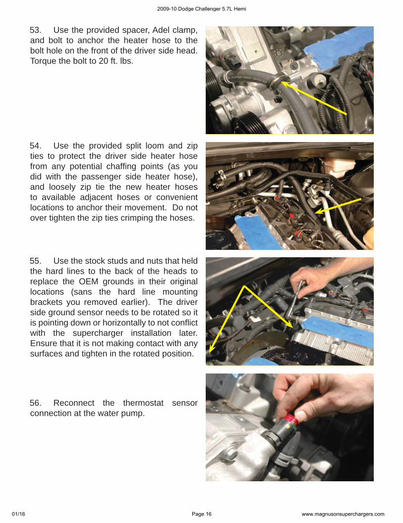
53. Use the provided spacer, Adel clamp, and bolt to anchor the heater hose to the bolt hole on the front of the driver side head. Torque the bolt to 20 ft. lbs.
54. Use the provided split loom and zip ties to protect the driver side heater hose from any potential chaffi ng points (as you did with the passenger side heater hose), and loosely zip tie the new heater hoses to available adjacent hoses or convenient locations to anchor their movement. Do not over tighten the zip ties crimping the hoses.
55. Use the stock studs and nuts that held the hard lines to the back of the heads to replace the OEM grounds in their original locations (sans the hard line mounting brackets you removed earlier). The driver side ground sensor needs to be rotated so it is pointing down or horizontally to not confl ict with the supercharger installation later. Ensure that it is not making contact with any surfaces and tighten in the rotated position.
56. Reconnect the thermostat sensor connection at the water pump.
2009-10 Dodge Challenger 5.7L Hemi
01/16 Page 16 www.magnusonsuperchargers.com
57. Disconnect the fan electrical power connection on the passenger side of the fan shroud assembly.
58. Remove the 10mm bolt from the air box mount on the driver side front of the engine compartment and pull the air box assembly out of the vehicle for later reinstall.
59. Use an 8mm wrench to remove the two fan shroud mounting bolts, there is one bolt on each side of the shroud.
60. Remove the fan shroud assembly from the vehicle by carefully pulling the unit up and out for reinstallation later. You can alternately pull the shroud from the vehicle from the bottom.
2009-10 Dodge Challenger 5.7L Hemi
01/16 Page 17 www.magnusonsuperchargers.com
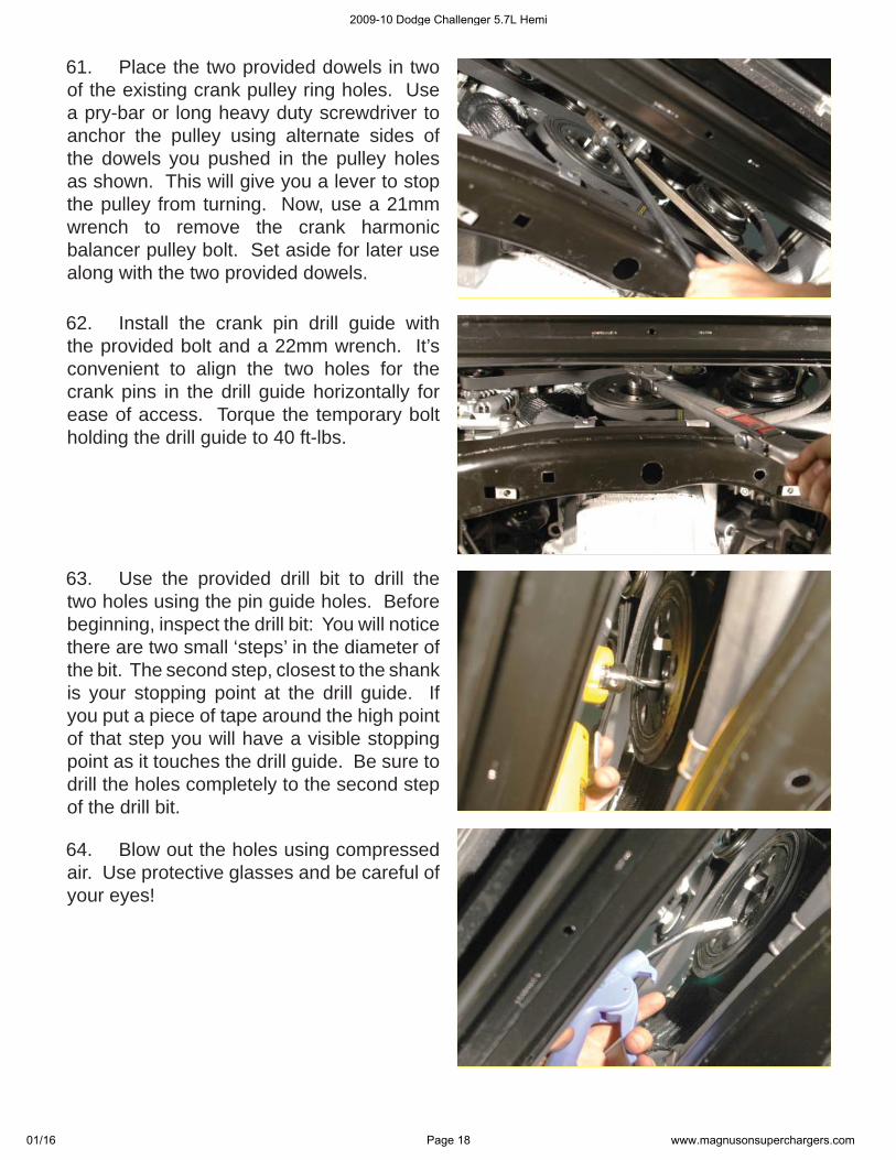
61. Place the two provided dowels in two of the existing crank pulley ring holes. Use a pry-bar or long heavy duty screwdriver to anchor the pulley using alternate sides of the dowels you pushed in the pulley holes as shown. This will give you a lever to stop the pulley from turning. Now, use a 21mm wrench to remove the crank harmonic balancer pulley bolt. Set aside for later use along with the two provided dowels.
62. Install the crank pin drill guide with the provided bolt and a 22mm wrench. It’s convenient to align the two holes for the crank pins in the drill guide horizontally for ease of access. Torque the temporary bolt holding the drill guide to 40 ft-lbs.
63. Use the provided drill bit to drill the two holes using the pin guide holes. Before beginning, inspect the drill bit: You will notice there are two small ‘steps’ in the diameter of the bit. The second step, closest to the shank is your stopping point at the drill guide. If you put a piece of tape around the high point of that step you will have a visible stopping point as it touches the drill guide. Be sure to drill the holes completely to the second step of the drill bit.
64. Blow out the holes using compressed air. Use protective glasses and be careful of your eyes!
2009-10 Dodge Challenger 5.7L Hemi
01/16 Page 18 www.magnusonsuperchargers.com
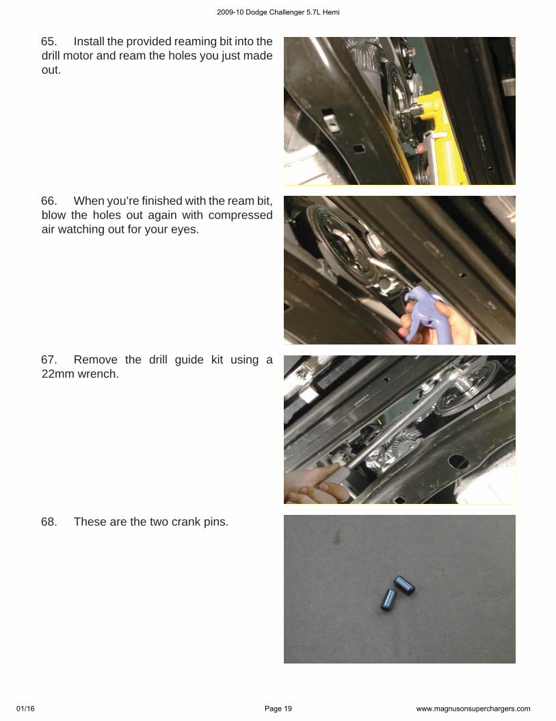
65. Install the provided reaming bit into the drill motor and ream the holes you just made out.
66. When you’re fi nished with the ream bit, blow the holes out again with compressed air watching out for your eyes.
67. Remove the drill guide kit using a 22mm wrench.
68. These are the two crank pins.
2009-10 Dodge Challenger 5.7L Hemi
01/16 Page 19 www.magnusonsuperchargers.com
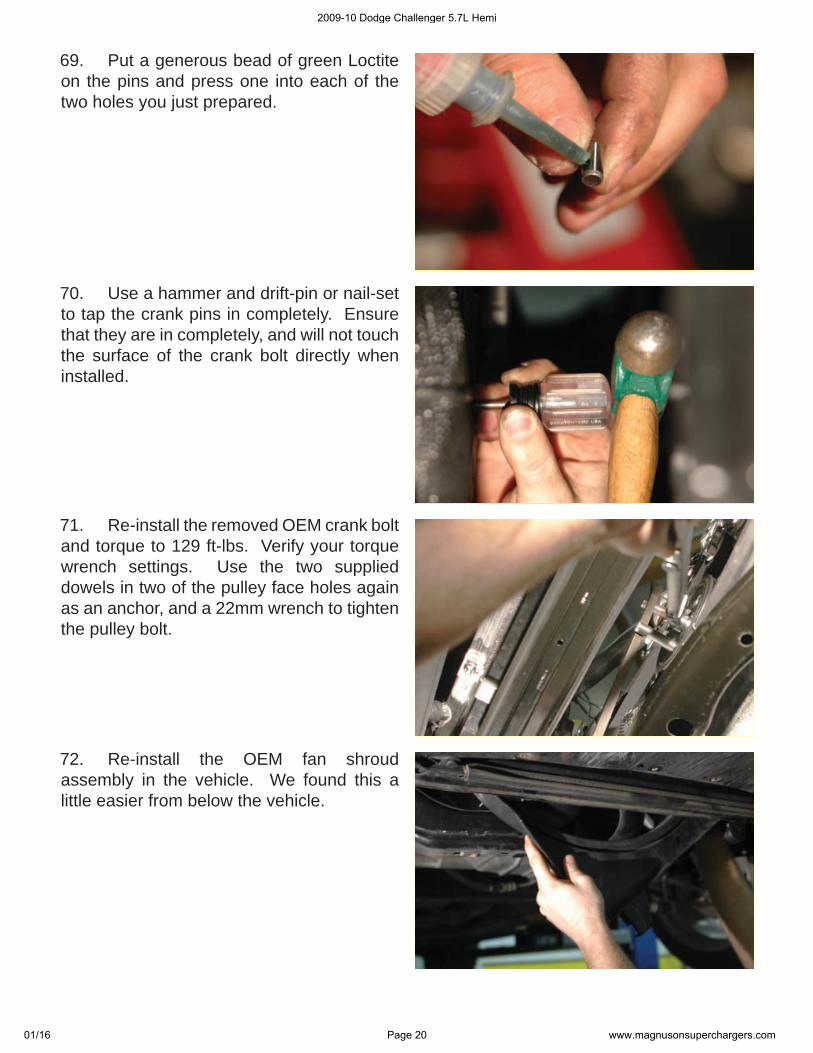
69. Put a generous bead of green Loctite on the pins and press one into each of the two holes you just prepared.
70. Use a hammer and drift-pin or nail-set to tap the crank pins in completely. Ensure that they are in completely, and will not touch the surface of the crank bolt directly when installed.
71. Re-install the removed OEM crank bolt and torque to 129 ft-lbs. Verify your torque wrench settings. Use the two supplied dowels in two of the pulley face holes again as an anchor, and a 22mm wrench to tighten the pulley bolt.
72. Re-install the OEM fan shroud assembly in the vehicle. We found this a little easier from below the vehicle.
2009-10 Dodge Challenger 5.7L Hemi
01/16 Page 20 www.magnusonsuperchargers.com
73. Anchor the fan shroud in place using an 8mm wrench for the two OEM mounting bolts.
74. Re-connect the fan control plug.
75. Clean up the end cap surfaces of the heat exchanger using acetone or lacquer thinner. Cut the supplied sticky backed foam strip to fi t the length of the end caps and attach to the inside surface of the end cap as shown.
76. Cut the adhesive backed rubber strips and affi x to the inside surface of two of the supplied heat exchanger mounting hooks. Apply a strip of the adhesive backed foam to the remaining heat exchanger mounting hook.
2009-10 Dodge Challenger 5.7L Hemi
01/16 Page 21 www.magnusonsuperchargers.com
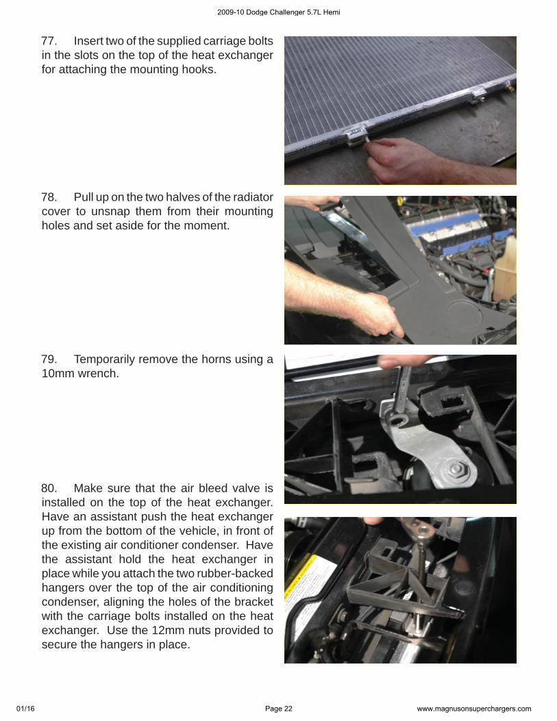
77. Insert two of the supplied carriage bolts in the slots on the top of the heat exchanger for attaching the mounting hooks.
78. Pull up on the two halves of the radiator cover to unsnap them from their mounting holes and set aside for the moment.
79. Temporarily remove the horns using a 10mm wrench.
80. Make sure that the air bleed valve is installed on the top of the heat exchanger. Have an assistant push the heat exchanger up from the bottom of the vehicle, in front of the existing air conditioner condenser. Have the assistant hold the heat exchanger in place while you attach the two rubber-backed hangers over the top of the air conditioning condenser, aligning the holes of the bracket with the carriage bolts installed on the heat exchanger. Use the 12mm nuts provided to secure the hangers in place.
2009-10 Dodge Challenger 5.7L Hemi
01/16 Page 22 www.magnusonsuperchargers.com
81. Replace the horns using the original hardware.
82. Attach the remaining carriage bolt to the passenger side mounting slot on the bottom of the heat exchanger. The remaining vibration damper foam backed bracket will clamp over the bottom of the air conditioning condenser and be secured to the carriage bolt just installed using the remaining 12mm nut.
83. On the front driver side of the engine compartment, below the air box location there is a cross frame plate with the air box inlet hole and a large ground wire. Open two existing holes to accommodate the intercooler pump using a ¼” drill bit. Image here is viewed from below.
84. Test the holes with the provided bolts for the intercooler pump mounting bracket. It should look like this as viewed from below.
2009-10 Dodge Challenger 5.7L Hemi
01/16 Page 23 www.magnusonsuperchargers.com
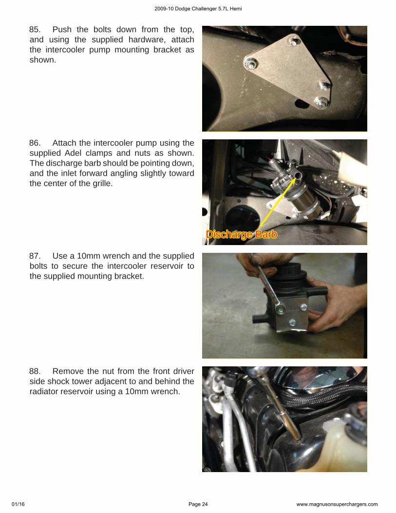
Discharge BarbDischarge Barb
85. Push the bolts down from the top, and using the supplied hardware, attach the intercooler pump mounting bracket as shown.
86. Attach the intercooler pump using the supplied Adel clamps and nuts as shown. The discharge barb should be pointing down, and the inlet forward angling slightly toward the center of the grille.
87. Use a 10mm wrench and the supplied bolts to secure the intercooler reservoir to the supplied mounting bracket.
88. Remove the nut from the front driver side shock tower adjacent to and behind the radiator reservoir using a 10mm wrench.
2009-10 Dodge Challenger 5.7L Hemi
01/16 Page 24 www.magnusonsuperchargers.com
89. Install the intercooler reservoir mounting bracket assembly and secure using the removed nut using a 10mm wrench as shown.
90. Cut off the short end of the two 4” x 60” x ¾” elbow hoses, leaving a little more than 1” of the short end (as measured from the inside of the curve).
91. Attach the short end of the hose to the passenger side hose barb on the front/bottom of the intercooler heat exchanger using one of the supplied spring clamps. The hose should be pointing toward the driver side of the vehicle. Route the long end of the hose along the fascia and up into the driver side of the engine compartment.
92. Attach the short end of the other 4” x 36” x ¾” you just modifi ed to the driver side hose barb of the intercooler heat exchanger using another of the supplied spring clamps.
2009-10 Dodge Challenger 5.7L Hemi
01/16 Page 25 www.magnusonsuperchargers.com
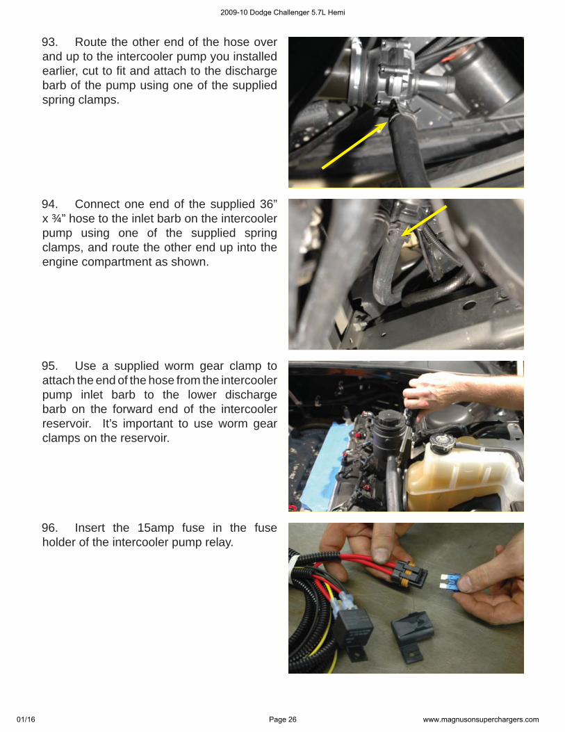
93. Route the other end of the hose over and up to the intercooler pump you installed earlier, cut to fi t and attach to the discharge barb of the pump using one of the supplied spring clamps.
94. Connect one end of the supplied 36” x ¾” hose to the inlet barb on the intercooler pump using one of the supplied spring clamps, and route the other end up into the engine compartment as shown.
95. Use a supplied worm gear clamp to attach the end of the hose from the intercooler pump inlet barb to the lower discharge barb on the forward end of the intercooler reservoir. It’s important to use worm gear clamps on the reservoir.
96. Insert the 15amp fuse in the fuse holder of the intercooler pump relay.
2009-10 Dodge Challenger 5.7L Hemi
01/16 Page 26 www.magnusonsuperchargers.com
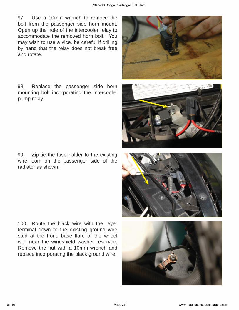
97. Use a 10mm wrench to remove the bolt from the passenger side horn mount. Open up the hole of the intercooler relay to accommodate the removed horn bolt. You may wish to use a vice, be careful if drilling by hand that the relay does not break free and rotate.
98. Replace the passenger side horn mounting bolt incorporating the intercooler pump relay.
99. Zip-tie the fuse holder to the existing wire loom on the passenger side of the radiator as shown.
100. Route the black wire with the “eye” terminal down to the existing ground wire stud at the front, base fl are of the wheel well near the windshield washer reservoir. Remove the nut with a 10mm wrench and replace incorporating the black ground wire.
2009-10 Dodge Challenger 5.7L Hemi
01/16 Page 27 www.magnusonsuperchargers.com
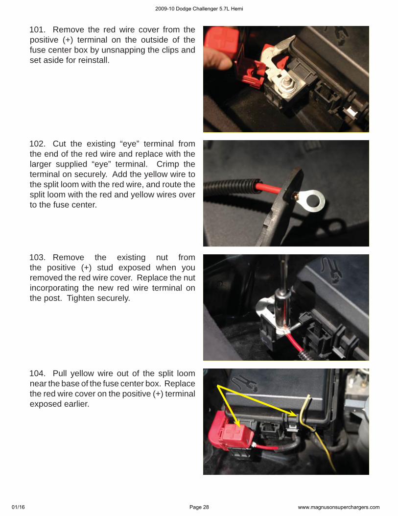
101. Remove the red wire cover from the positive (+) terminal on the outside of the fuse center box by unsnapping the clips and set aside for reinstall.
102. Cut the existing “eye” terminal from the end of the red wire and replace with the larger supplied “eye” terminal. Crimp the terminal on securely. Add the yellow wire to the split loom with the red wire, and route the split loom with the red and yellow wires over to the fuse center.
103. Remove the existing nut from the positive (+) stud exposed when you removed the red wire cover. Replace the nut incorporating the new red wire terminal on the post. Tighten securely.
104. Pull yellow wire out of the split loom near the base of the fuse center box. Replace the red wire cover on the positive (+) terminal exposed earlier.
2009-10 Dodge Challenger 5.7L Hemi
01/16 Page 28 www.magnusonsuperchargers.com
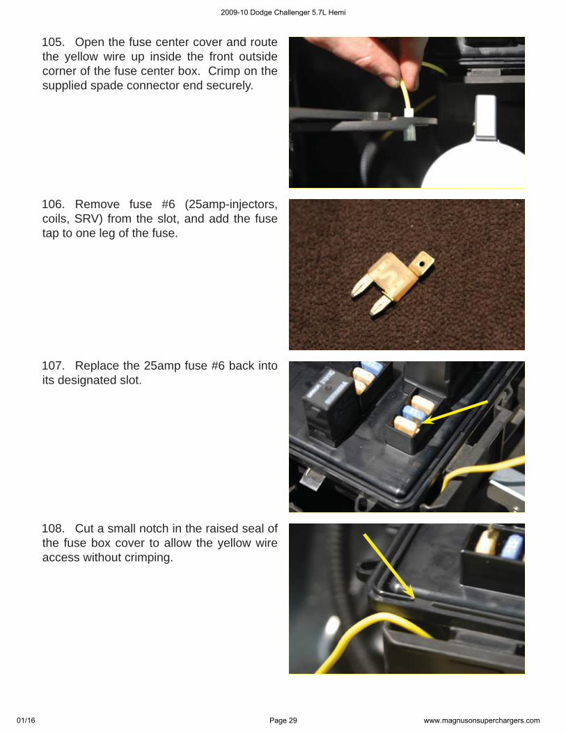
105. Open the fuse center cover and route the yellow wire up inside the front outside corner of the fuse center box. Crimp on the supplied spade connector end securely.
106. Remove fuse #6 (25amp-injectors, coils, SRV) from the slot, and add the fuse tap to one leg of the fuse.
107. Replace the 25amp fuse #6 back into its designated slot.
108. Cut a small notch in the raised seal of the fuse box cover to allow the yellow wire access without crimping.
2009-10 Dodge Challenger 5.7L Hemi
01/16 Page 29 www.magnusonsuperchargers.com
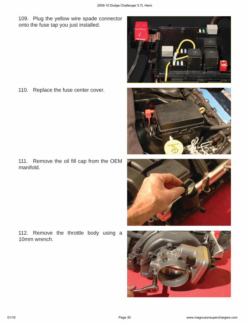
109. Plug the yellow wire spade connector onto the fuse tap you just installed.
110. Replace the fuse center cover.
111. Remove the oil fi ll cap from the OEM manifold.
112. Remove the throttle body using a 10mm wrench.
2009-10 Dodge Challenger 5.7L Hemi
01/16 Page 30 www.magnusonsuperchargers.com
113. The provided 2-Bar MAP sensor has to be modifi ed. Cut off the outside fi n on the top-left side and fi le smooth. It should look like this. Test fi t with the receiving connector before continuing.
114. Use the provided Lubriplate lubricant on the O-ring of the MAP sensor and press into the hole at the rear passenger side of the supercharger lid, behind the supercharger. Use an 11/16” wrench to disconnect the cross-over fuel line at the rear of the fuel rail on the passenger side.
115. Secure the MAP sensor fastener using a Phillips head screwdriver. Now re-install the fuel cross-over line.
116. Attach the oil fi ll cap removed from the OEM intake manifold.
2009-10 Dodge Challenger 5.7L Hemi
01/16 Page 31 www.magnusonsuperchargers.com
117. Install the provided throttle body O-ring on the supercharger inlet. Place a bead of the provided Lubriplate lubricant on the O-ring to help hold it in place.
118. Use the provided throttle body bolts to mount the throttle body on the new intake. Use some of the provided blue Loctite on the mounting bolts and mount the OEM throttle body to the supercharger inlet and tighten using a 10mm torque wrench to 106 in. lbs.
119. Lube the O-ring of the provided PCV valve with the provided Lubriplate lubricant, and thread into the passenger side mounting hole between the fuel rails and near the rear of the supercharger. Snug down using a 15/16” wrench.
120. Flip the supercharger assembly upside down on some clean shop towels and use a 4mm Allen wrench to remove the hold-down bracket.
2009-10 Dodge Challenger 5.7L Hemi
01/16 Page 32 www.magnusonsuperchargers.com
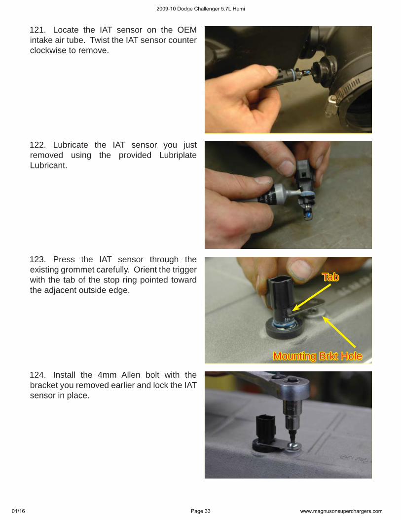
121. Locate the IAT sensor on the OEM intake air tube. Twist the IAT sensor counter clockwise to remove.
122. Lubricate the IAT sensor you just removed using the provided Lubriplate Lubricant.
123. Press the IAT sensor through the existing grommet carefully. Orient the trigger with the tab of the stop ring pointed toward the adjacent outside edge.
124. Install the 4mm Allen bolt with the bracket you removed earlier and lock the IAT sensor in place.
TabTab
Mounting Brkt HoleMounting Brkt Hole
2009-10 Dodge Challenger 5.7L Hemi
01/16 Page 33 www.magnusonsuperchargers.com
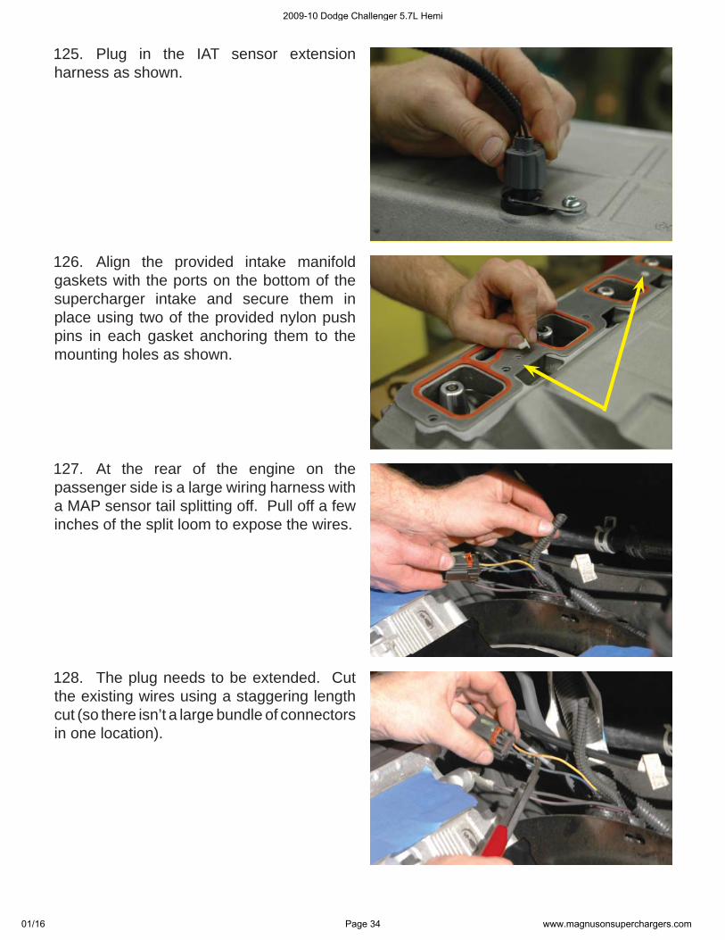
125. Plug in the IAT sensor extension harness as shown.
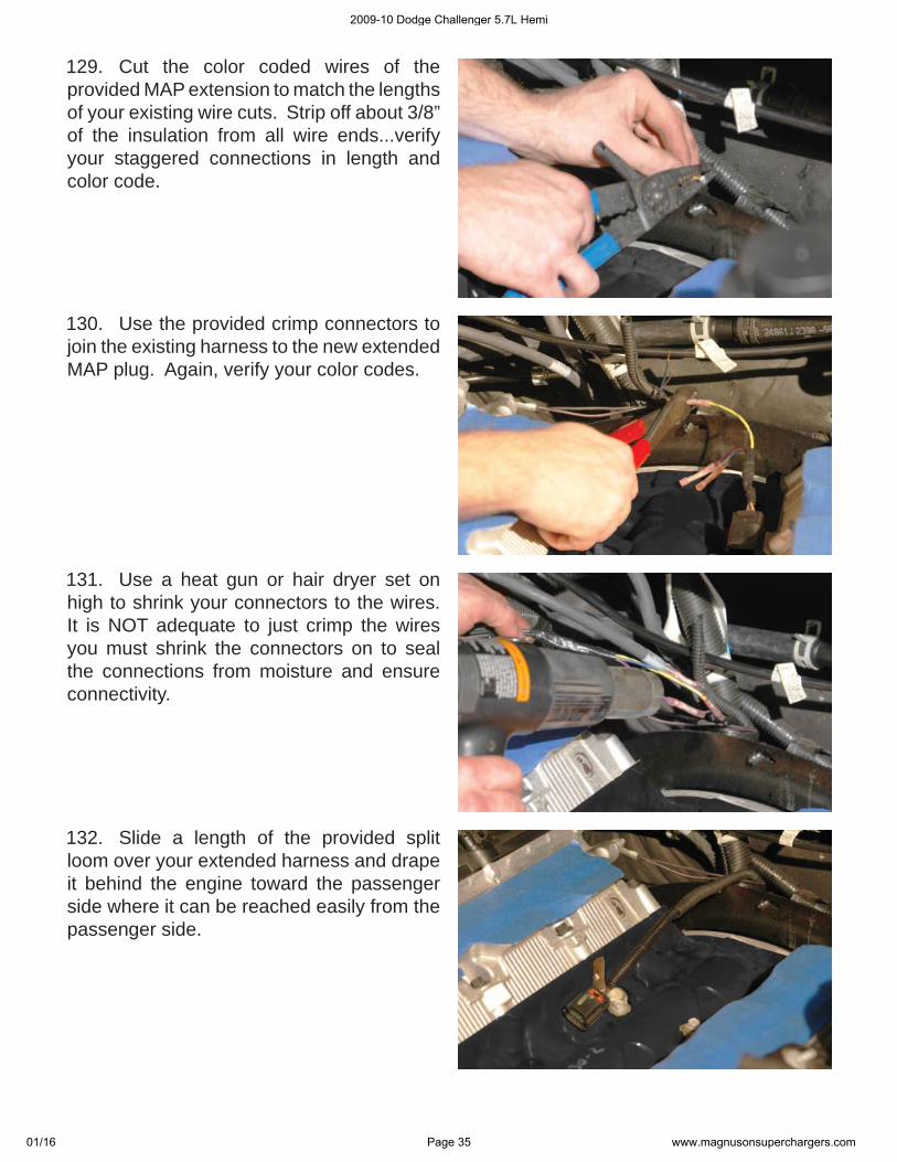
126. Align the provided intake manifold gaskets with the ports on the bottom of the supercharger intake and secure them in place using two of the provided nylon push pins in each gasket anchoring them to the mounting holes as shown.
127. At the rear of the engine on the passenger side is a large wiring harness with a MAP sensor tail splitting off. Pull off a few inches of the split loom to expose the wires.
128. The plug needs to be extended. Cut the existing wires using a staggering length cut (so there isn’t a large bundle of connectors in one location).
2009-10 Dodge Challenger 5.7L Hemi
01/16 Page 34 www.magnusonsuperchargers.com
129. Cut the color coded wires of the provided MAP extension to match the lengths of your existing wire cuts. Strip off about 3/8” of the insulation from all wire ends...verify your staggered connections in length and color code.
130. Use the provided crimp connectors to join the existing harness to the new extended MAP plug. Again, verify your color codes.
131. Use a heat gun or hair dryer set on high to shrink your connectors to the wires. It is NOT adequate to just crimp the wires you must shrink the connectors on to seal the connections from moisture and ensure connectivity.
132. Slide a length of the provided split loom over your extended harness and drape it behind the engine toward the passenger side where it can be reached easily from the passenger side.
2009-10 Dodge Challenger 5.7L Hemi
01/16 Page 35 www.magnusonsuperchargers.com
133. Remove the tape or rags you placed over the ports of the head.
134. Wipe the surfaces clean again using lacquer thinner, alcohol or some other non-petroleum based product.
135. Spray a mist of silicone lubricant, mild soapy water, or some other non-petroleum based lubricant on the ports of the head to allow easy alignment of the supercharger assembly to the heads.
136. With the help of an assistant, carefully place the supercharger assembly over the intake gaskets on the heads, verify your bolt alignment and that the gaskets haven’t shifted. The IAT harness should exit from below the supercharger toward the front of the engine on the passenger side.
2009-10 Dodge Challenger 5.7L Hemi
01/16 Page 36 www.magnusonsuperchargers.com
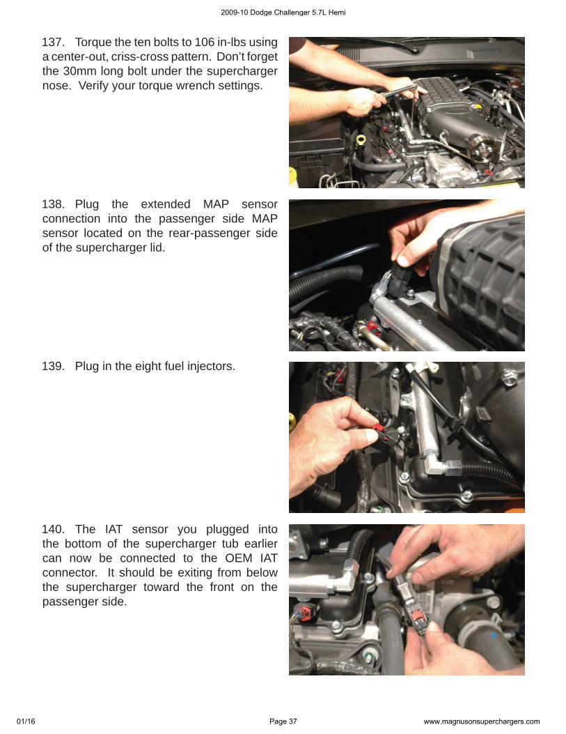
137. Torque the ten bolts to 106 in-lbs using a center-out, criss-cross pattern. Don’t forget the 30mm long bolt under the supercharger nose. Verify your torque wrench settings.
138. Plug the extended MAP sensor connection into the passenger side MAP sensor located on the rear-passenger side of the supercharger lid.
139. Plug in the eight fuel injectors.
140. The IAT sensor you plugged into the bottom of the supercharger tub earlier can now be connected to the OEM IAT connector. It should be exiting from below the supercharger toward the front on the passenger side.
2009-10 Dodge Challenger 5.7L Hemi
01/16 Page 37 www.magnusonsuperchargers.com
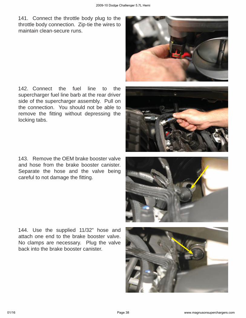
141. Connect the throttle body plug to the throttle body connection. Zip-tie the wires to maintain clean-secure runs.
142. Connect the fuel line to the supercharger fuel line barb at the rear driver side of the supercharger assembly. Pull on the connection. You should not be able to remove the fi tting without depressing the locking tabs.
143. Remove the OEM brake booster valve and hose from the brake booster canister. Separate the hose and the valve being careful to not damage the fi tting.
144. Use the supplied 11/32” hose and attach one end to the brake booster valve. No clamps are necessary. Plug the valve back into the brake booster canister.
2009-10 Dodge Challenger 5.7L Hemi
01/16 Page 38 www.magnusonsuperchargers.com
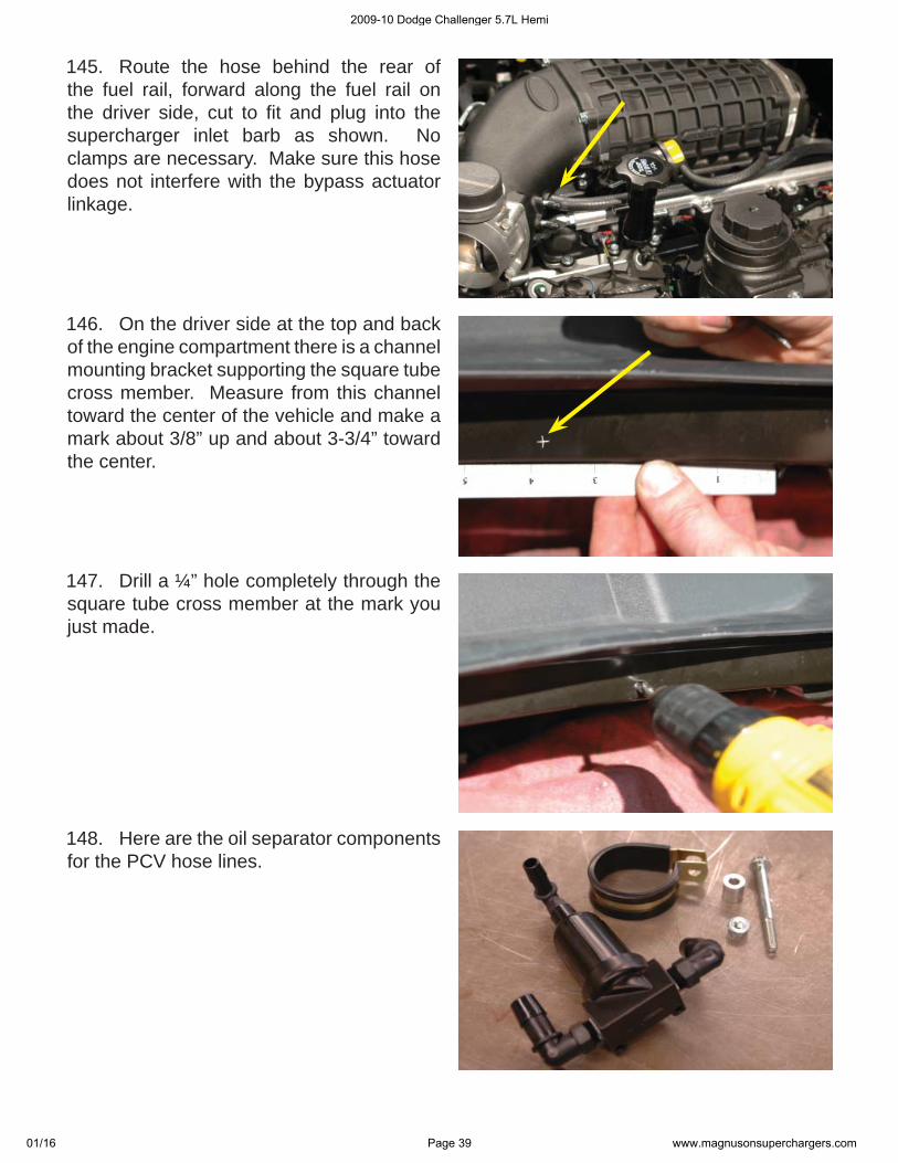
145. Route the hose behind the rear of the fuel rail, forward along the fuel rail on the driver side, cut to fi t and plug into the supercharger inlet barb as shown. No clamps are necessary. Make sure this hose does not interfere with the bypass actuator linkage.
146. On the driver side at the top and back of the engine compartment there is a channel mounting bracket supporting the square tube cross member. Measure from this channel toward the center of the vehicle and make a mark about 3/8” up and about 3-3/4” toward the center.
147. Drill a ¼” hole completely through the square tube cross member at the mark you just made.
148. Here are the oil separator components for the PCV hose lines.
2009-10 Dodge Challenger 5.7L Hemi
01/16 Page 39 www.magnusonsuperchargers.com
149. Use the provided Adel clamp and spacer and bolt/nut to mount the oil separator to the holes through the square tube.
150. Connect one end of the provided 3/8” x 12-1/2” hose to the bottom barb of the oil separator valve.
151. Connect the other end of the provided 3/8” hose on the rear barb below the oil fi ll cap on the oil fi ll neck.
152. Connect a section of the provided ½” hose to the driver side barb of the oil separator valve.
2009-10 Dodge Challenger 5.7L Hemi
01/16 Page 40 www.magnusonsuperchargers.com
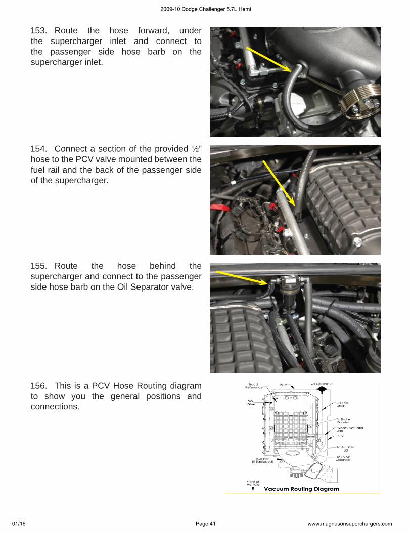
153. Route the hose forward, under the supercharger inlet and connect to the passenger side hose barb on the supercharger inlet.
154. Connect a section of the provided ½” hose to the PCV valve mounted between the fuel rail and the back of the passenger side of the supercharger.
155. Route the hose behind the supercharger and connect to the passenger side hose barb on the Oil Separator valve.
156. This is a PCV Hose Routing diagram to show you the general positions and connections.
2009-10 Dodge Challenger 5.7L Hemi
01/16 Page 41 www.magnusonsuperchargers.com
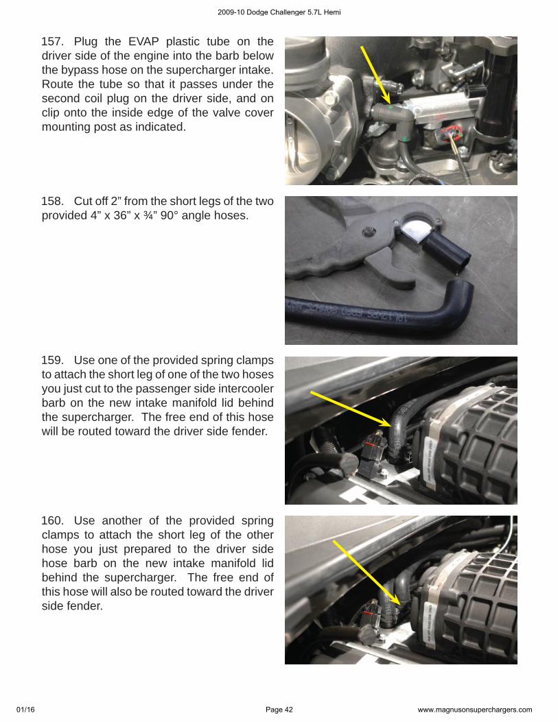
157. Plug the EVAP plastic tube on the driver side of the engine into the barb below the bypass hose on the supercharger intake. Route the tube so that it passes under the second coil plug on the driver side, and on clip onto the inside edge of the valve cover mounting post as indicated.
158. Cut off 2” from the short legs of the two provided 4” x 36” x ¾” 90° angle hoses.
159. Use one of the provided spring clamps to attach the short leg of one of the two hoses you just cut to the passenger side intercooler barb on the new intake manifold lid behind the supercharger. The free end of this hose will be routed toward the driver side fender.
160. Use another of the provided spring clamps to attach the short leg of the other hose you just prepared to the driver side hose barb on the new intake manifold lid behind the supercharger. The free end of this hose will also be routed toward the driver side fender.
2009-10 Dodge Challenger 5.7L Hemi
01/16 Page 42 www.magnusonsuperchargers.com
161. Use the provided ¾” x ¾” hose coupling (mender) and two of the provide spring clamps to join the driver side hose you just installed to the hose you ran up into the engine compartment from the intercooler pump. This hose should be routed just below the intercooler reservoir.
162. Route the passenger side intercooler hose you just installed over to the intercooler reservoir. Cut to fi t and secure to the intercooler reservoir using one of the provided worm gear clamps.
163. 163. Mount the provided Idler bracket to the Mount the provided Idler bracket to the supercharger assembly with the provided M8 supercharger assembly with the provided M8 x 35 mm bolts (2 each). Install the two 0.2” x 35 mm bolts (2 each). Install the two 0.2” spacers behind the bracket where shown spacers behind the bracket where shown with the two arrows. Torque the mounting with the two arrows. Torque the mounting bolts to 20 ft-lbs with a 12mm socket.bolts to 20 ft-lbs with a 12mm socket.
164. Using a 3/8” drive ratchet or breaker bar, spring the tensioner and install the serpentine belt using the belt routing diagram provided in the back of the instruction manual.
2009-10 Dodge Challenger 5.7L Hemi
01/16 Page 43 www.magnusonsuperchargers.com
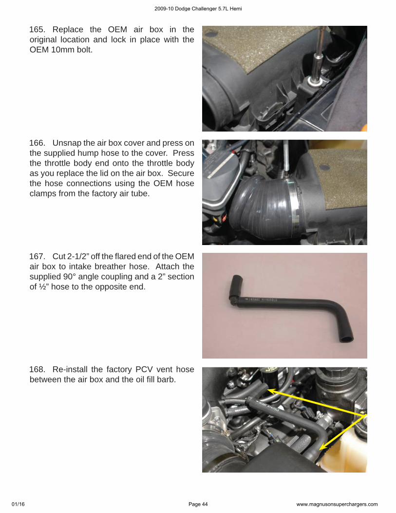
165. Replace the OEM air box in the original location and lock in place with the OEM 10mm bolt.
166. Unsnap the air box cover and press on the supplied hump hose to the cover. Press the throttle body end onto the throttle body as you replace the lid on the air box. Secure the hose connections using the OEM hose clamps from the factory air tube.
167. Cut 2-1/2” off the fl ared end of the OEM air box to intake breather hose. Attach the supplied 90° angle coupling and a 2” section of ½” hose to the opposite end.
168. Re-install the factory PCV vent hose between the air box and the oil fi ll barb.
2009-10 Dodge Challenger 5.7L Hemi
01/16 Page 44 www.magnusonsuperchargers.com
169. Re-attach the battery negative (-) connection in the trunk using a 10mm wrench.
170. Refi ll the radiator using the drained strained fl uid removed earlier and top off as necessary after verifying that the drain valve is closed.
171. Fill the intercooler system with a 50-50 mixture of distilled water and coolant. Use the bleed valve at the front passenger side of the heat exchanger to help eliminate air from the system. The intercooler system will hold approximately six quarts of liquid. Fill the reservoir until the fl uid level comes to about one and a quarter inch from the top edge of the fi ller neck
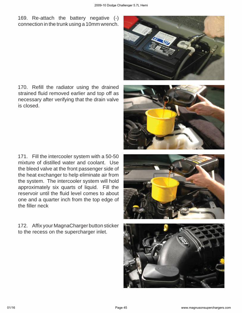
172. Affi x your MagnaCharger button sticker to the recess on the supercharger inlet.
2009-10 Dodge Challenger 5.7L Hemi
01/16 Page 45 www.magnusonsuperchargers.com
173. Replace the forward splash shield using the OEM fasteners.
174. Replace the rear splash shield utilizing the OEM fasteners.
175. Start the vehicle for fi ve seconds and shut off. Check for fuel, coolant leaks and supercharger belt alignment. Check radiator and intercooler reservoir levels and top off as necessary.
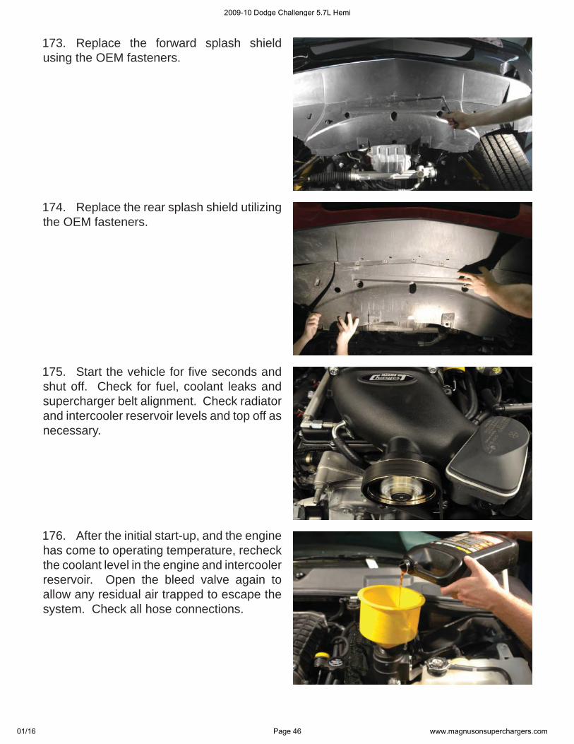
176. After the initial start-up, and the engine has come to operating temperature, recheck the coolant level in the engine and intercooler reservoir. Open the bleed valve again to allow any residual air trapped to escape the system. Check all hose connections.
2009-10 Dodge Challenger 5.7L Hemi
01/16 Page 46 www.magnusonsuperchargers.com
177. Replace the factory radiator covers utilizing the OEM fasteners, and affi x the Premium Fuel Only sticker to a conspicuous location under the hood.
178. Affi x the Premium Fuel Only sticker to the door of your gas fi ll cap.
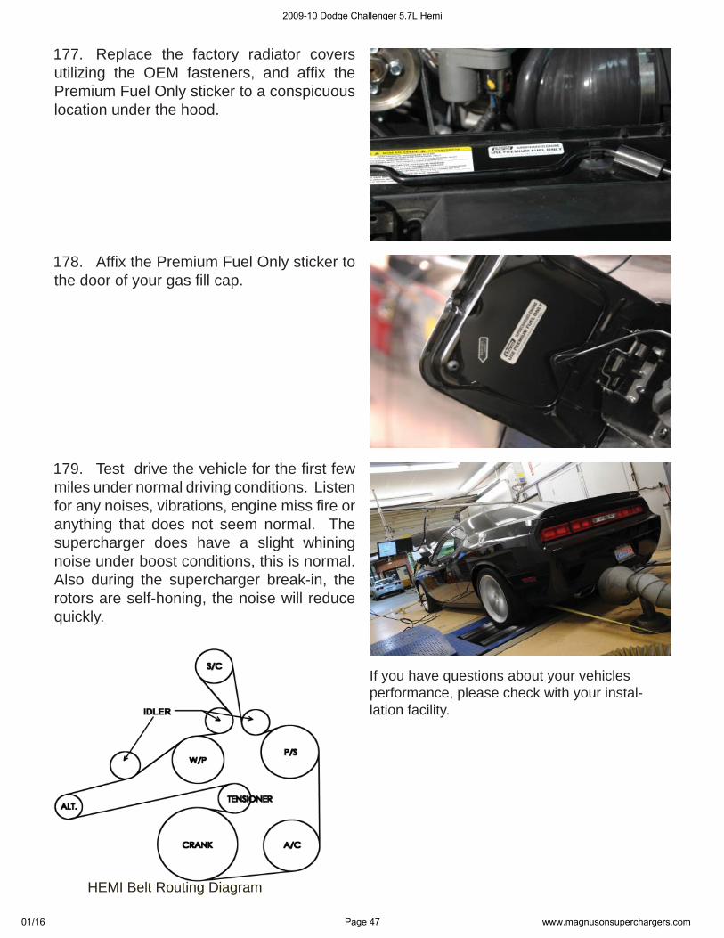
179. Test drive the vehicle for the fi rst few miles under normal driving conditions. Listen for any noises, vibrations, engine miss fi re or anything that does not seem normal. The supercharger does have a slight whining noise under boost conditions, this is normal. Also during the supercharger break-in, the rotors are self-honing, the noise will reduce quickly.
If you have questions about your vehicles performance, please check with your instal-lation facility.
HEMI Belt Routing DiagramHEMI Belt Routing Diagram