Dash Disassembly1996-1999 Infiniti I-30 ................................................................. 11993-1995 Mercury Villager /1993-1995 Nissan Quest ............... 21996-1998 Mercury Villager/ 1996-1998 Nissan Quest ............... 31999-2002 Mercury Villager /1999-2003 Nissan Quest................ 41995-1999 Nissan Sentra /1995-1998 200 SX............................. 51995-1998 Nissan 240 SX ............................................................ 61998-2001 Nissan Altima ............................................................. 71998-2001 Nissan Frontier/2000-2001 Nissan Xterra ................. 82002-2004 Nissan Frontier/2002-2004 Nissan Xterra ................. 91995-1999 Nissan Maxima......................................................... 102000-2003 Nissan Maxima......................................................... 111996-2000 Nissan Pathfinder/QX4 1997-2000........................... 122001-2004 Nissan Pathfinder..................................................... 13Fits all models EXCEPT the Bose and Comfort & Convenience pkgs.Kit AssemblyDouble DIN Head Unit Provision.................................................. 14Stacked ISO DIN Head Unit Provision ......................................... 15 Final Assembly ............................................................................16
CAUTION:Do not cycle the key when removing a dash with passengerairbag ON/OFF switch.
*
*
KNOWLEDGE IS POWEREnhance your installation and fabrication skillsby enrolling in the most recognized and respected mobile electronics school in our industry.Log onto www.installerinstitute.comor call 800-354-6782 for more information and take steps toward a better tomorrow.
95-7417
1
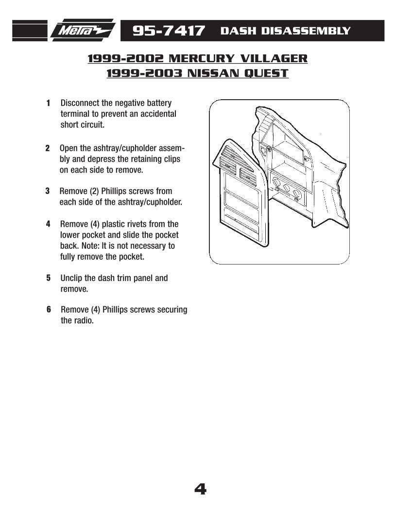
Disconnect the negative battery terminal to prevent an accidentalshort circuit.
1
Unclip and remove the shift levertrim panel and remove the (2)screws exposed.
2
1996-1999 INFINITI I-30
Remove (1) screw to the left of theashtray then unclip and remove theashtray assembly.
3
Unclip and remove the clock/ventassembly.
4
Remove (4) screws securing theradio.
5
DASH DISASSEMBLY
95-7417 DASH DISASSEMBLY
1993-1995 MERCURY VILLAGER1993-1995 NISSAN QUEST
Disconnect the negative battery terminal to prevent an accidentalshort circuit.
Remove (1) screw above the climatecontrols.
2
Unclip and remove the radio trimpanel.
3
Remove (4) screws securing theradio.
4
1
2
3
Disconnect the negative battery terminal to prevent an accidentalshort circuit.
1
Remove (4) plastic screws andscrew anchors from the base of thestorage compartment then removethe compartment.
2
Remove (2) Phillips screws fromabove the radio opening.
4
Remove the ashtray.5
Remove (4) screws securing theradio.
6
Remove (2) Phillips screws from thebase of the radio trim panel.
3
95-7417 DASH DISASSEMBLY
1996-1998 MERCURY VILLAGER1996-1998 NISSAN QUEST
Disconnect the negative battery terminal to prevent an accidentalshort circuit.
1
4
95-7417 DASH DISASSEMBLY
Open the ashtray/cupholder assem-bly and depress the retaining clipson each side to remove.
2
Remove (2) Phillips screws fromeach side of the ashtray/cupholder.
3
Unclip the dash trim panel andremove.
5
Remove (4) Phillips screws securingthe radio.
6
Remove (4) plastic rivets from thelower pocket and slide the pocketback. Note: It is not necessary tofully remove the pocket.
4
1999-2002 MERCURY VILLAGER1999-2003 NISSAN QUEST
5
Unclip and remove the dummy plateabove the climate controls.
2
Remove (1) Phillips screw frombehind dummy plate.
3
Unclip and remove radio trim panel.4
Remove (4) Phillips screws securingradio.
5
95-7417 DASH DISASSEMBLY
1995-1999 NISSAN SENTRA1995-1998 200 SX
Disconnect the negative battery terminal to prevent an accidentalshort circuit.
1
6
95-7417
1995-1998 NISSAN 240 SX
DASH DISASSEMBLY
Disconnect the negative battery ter-minal to prevent an accidental shortcircuit.
Unclip and remove the climate con-trol trim panel and remove the (2)exposed behind.
Unclip and remove the shift levertrim panel and remove the (2) screwsexposed behind.
1
2
3
Remove the ashtray and (1) Phillipsscrew exposed in the ashtray cavity.
4
Unclip and remove the radio trimpanel, factory radio and pocketassembly.
5
95-7417 DASH DISASSEMBLY
1998-2001 NISSAN ALTIMA
7
Disconnect the negative battery terminalto prevent an accidental short circuit.
Unclip the shift lever trim panel andremove (2) Phillips screws at the baseof the radio trim panel.
Disconnect the negative battery terminalto prevent an accidental short circuit.
Remove the ashtray and the (2) Phillipsscrews exposed in the ashtray cavity.
1
2
Unclip and remove the radio trim panel.3
Remove (4) Phillips screws securing theradio.
4
95-7417 DASH DISASSEMBLY
2002-2004 NISSAN FRONTIER2002-2004 NISSAN XTERRA
9
Disconnect the negative battery terminalto prevent an accidental short circuit.
Unclip and remove the shift lever trimpanel.
1
2
Remove (2) Phillips screws exposed inthe shift lever cavity.
3
Remove (2) Phillips screws under theclimate control.
4
Unclip and remove the radio trim panel.5
Remove (4) Phillips screws securing theradio.
6
95-7417 DASH DISASSEMBLY
1995-1999 NISSAN MAXIMA
10
Disconnect the negative battery terminalto prevent an accidental short circuit.
Unclip the shift lever trim panel.
1
2
Remove the (2) Phillips screws at thebase of the radio trim panel.
3
Remove (1) Phillips screw to the left ofthe ashtray and unclip the ashtrayassembly.
4
Unclip and remove the clock/ventassembly.
5
Remove (4) Phillips screws securing theradio.
6
95-7417 DASH DISASSEMBLY
2000-2003 NISSAN MAXIMA
11
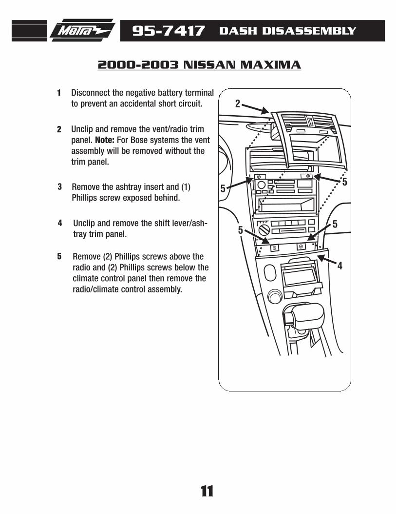
Disconnect the negative battery terminalto prevent an accidental short circuit.
Unclip and remove the vent/radio trimpanel. Note: For Bose systems the ventassembly will be removed without thetrim panel.
1
2
Remove the ashtray insert and (1)Phillips screw exposed behind.
3
2
4
5
55
5Unclip and remove the shift lever/ash-tray trim panel.
4
Remove (2) Phillips screws above theradio and (2) Phillips screws below theclimate control panel then remove theradio/climate control assembly.
5
95-7417 DASH DISASSEMBLY
1996-2000 NISSAN PATHFINDER/QX4 1997-2000
12
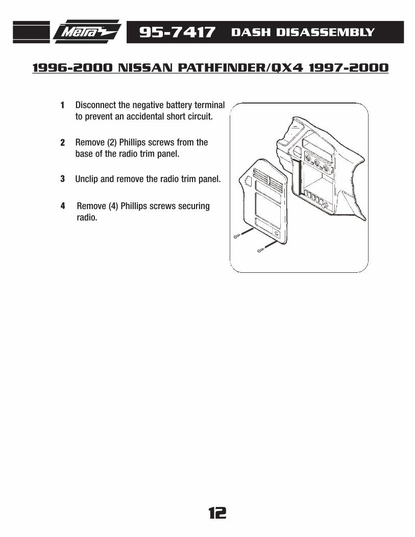
Disconnect the negative battery terminalto prevent an accidental short circuit.
Remove (2) Phillips screws from thebase of the radio trim panel.
1
2
Unclip and remove the radio trim panel.3
Remove (4) Phillips screws securingradio.
4
95-7417 DASH DISASSEMBLY
2001-2003 NISSAN PATHFINDER
13
Disconnect the negative battery terminalto prevent an accidental short circuit.
Unclip and remove the vent/clockassembly. (Figure A)
1
2
Remove (2) Phillips screws from the topof the radio trim panel then remove thepanel. (Figure B)
3
Remove (4) Phillips screws securingradio. (Figure C)
4
A
B
C
14
95-7417 KIT ASSEMBLY
2
A
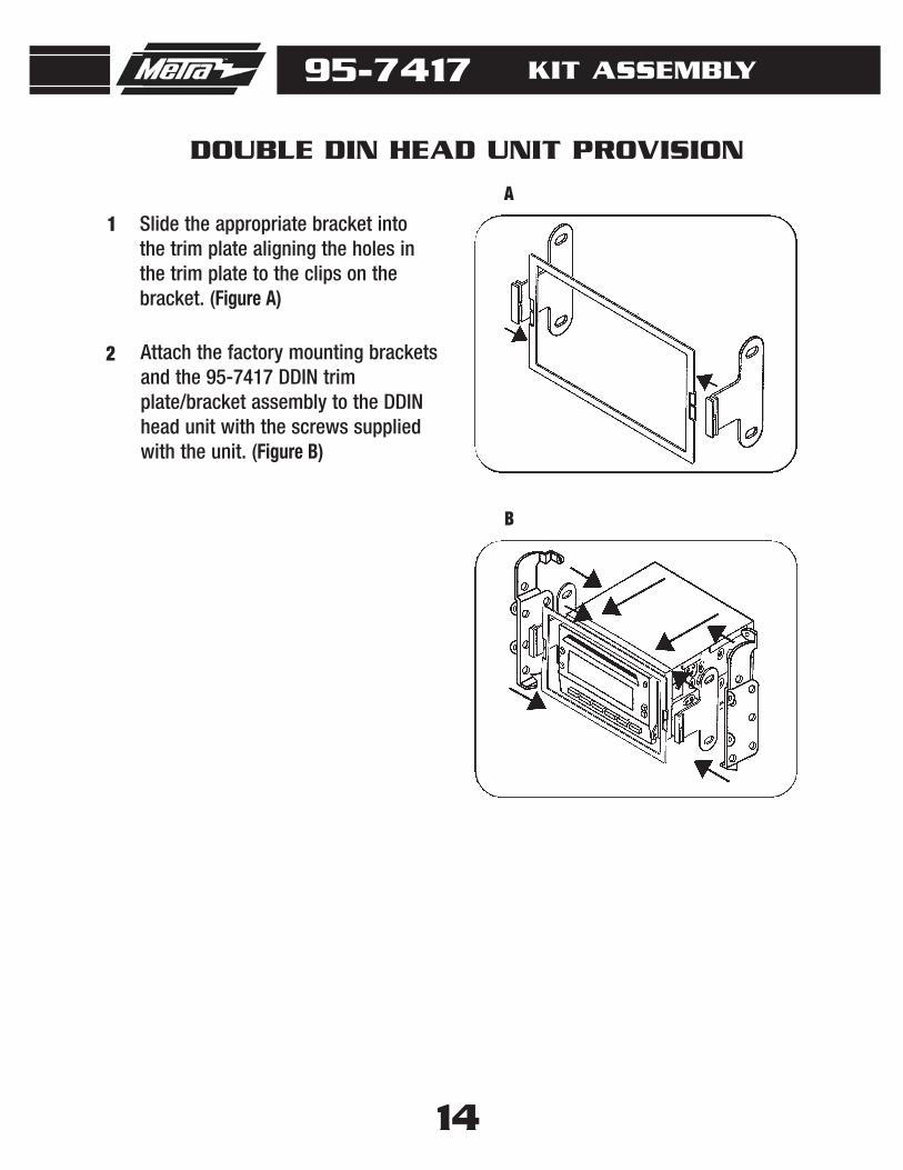
Attach the factory mounting bracketsand the 95-7417 DDIN trimplate/bracket assembly to the DDINhead unit with the screws suppliedwith the unit. (Figure B)
Slide the appropriate bracket intothe trim plate aligning the holes inthe trim plate to the clips on thebracket. (Figure A)
1
B
DOUBLE DIN HEAD UNIT PROVISION
95-7417 KIT ASSEMBLY
15
2
A
Attach the factory mounting bracketsand the 95-7417 DDIN trimplate/bracket assembly to thestacked ISO DIN head units with thescrews supplied with the units.(Figure B)
Slide the appropriate bracket intothe trim plate aligning the holes inthe trim plate to the clips on thebracket. (Figure A)
1
B
STACKED ISO DIN HEAD UNIT PROVISION
16
FINAL ASSEMBLY1 Locate the factory wiring harness in the dash and make the connection as shown.
Metra recomends using the proper mating adapter and making the connections asshown. (Isolate and individually tape off the ends of any unused wires to preventelectrical short circuit.)
2 Re-connect the negative battery terminal and test the unit for proper operation.3 Reassemble radio and dash assemblies in reverse order of disassembly.
A
A) Strip wire ends back 1/2"
B) Twist ends together
C) Solder
D) Tape
B
C
D
Make wiring connections using the EIA color code chart shown below and the instructions included with the headunit. Metra recommends making connections as shown below; Strip, Splice, Solder, Tape. Isolate and individuallytape off ends of any unused wires to prevent electrical short circuit.
12V Ignition / Acc . . . Red
12V Batt / Memory . . Yellow
Ground . . . . . . . . . . . Black*
Power Antenna . . . . . Blue
Amp Turn-On . . . . . . Blue / White
Amp Ground . . . . . . . Black / White
Illumination. . . . . . . . Orange
Dimmer . . . . . . . . . . Orange / White
Right Front (+) . . . . . Gray
Right Front (-) . . . . . . Gray / Black
Left Front (+) . . . . . . White
Left Front (-) . . . . . . . White / Black
Right Rear (+). . . . . . Violet
Right Rear (-) . . . . . . Violet / Black
Left Rear (+). . . . . . . Green
Left Rear (-) . . . . . . . Green / Black
*NOTE: When Black a wire is not present, ground radio to vehicle chassis.All colors may not be present on all leads due to manufacturer’s specifications.