*NOTE: Refer also to the instructions included with the aftermarket radio.
CAUTION : Metra recommends disconnecting the negative battery terminal before beginning any installation. All accessories, switch-es and especially air bag indicator lights must be plugged in before reconnecting the battery or cycling the ignition.
KNOWLEDGE IS POWEREnhance your installation and fabrication skills by enrolling in the most recognized and respected mobile electronics school in our industry.Log onto www.installerinstitute.com or call 800-354-6782 for more information and take steps toward a better tomorrow.
Metra recommends MECP certified technicians
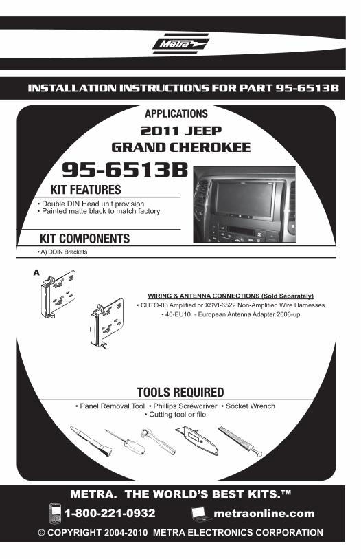
INSTALLATION INSTRUCTIONS FOR PART 95-6513B
2011 JEEP GRAND CHEROKEE
95-6513B DASH DISASSEMBLY
Unclip and remove panel from around the radio including the vents and the climate controls. (Fig. A)
Remove (4) 7MM screws securing radio to dash to remove. (Fig. B)
Remove (3) 7MM screws securing the radio bracket to the sub dash.(Fig. C)
Continue to Kit Preparation ..........
1
2
3
A
B
C
1
2
2011 JEEP GRAND CHEROKEE
95-6513B DASH PREPARATION
Modification to the sub dash is necessary for the aftermarket DDIN radio to fit. You will need to trim the top and bottom of the sub dash cavity. (Fig. A)
Continue to Kit Assembly .............
1 A
3
DDIN HEAD UNIT PROVISION
95-6513B KIT ASSEMBLY
Attach the Double DIN brackets to the after market radio using the screws supplied with the radio. (Fig. A)
Locate the factory wiring harness and antenna plug in the dash. Metra recommends using the proper mating adapters from Metra and/or AXXESS.
INSTRUCCIONES DE INSTALACIÓN PARA LA PIEZA 95-6513B
2011 JEEP GRAND CHEROKEE
95-6513B• Accesorio para unidades centrales DIN dobles• Pintado de color negro mate para que coincida con el color de fábrica
• A) Soportes DDIN
CONEXIONES DE CABLEADO Y ANTENA (se venden por separado)• CHTO-03 amplifi cado or XSVI-6522 no amplifi cado• 40-EU10 - Adaptador de antena Europa 2006-up
• Herramienta para retirar paneles • Destornillador Phillips • Llave de tubo• Herramienta de corte o lima
*NOTA: Consulte también las instrucciones incluidas con la radio del mer-cado de accesorios.
CAUTION : Metra recomienda desconectar el terminal negativo de la batería antes de comenzar cualquier instalación. Todos los acceso-rios, interruptores y, especialmente, las luces indicadoras de air-bag deben estar enchufados antes de volver a conectar la batería o comenzar el ciclo de ignición.
Conocimiento es PoderConvierta su hobby en una carrera en Installer Institute, el líder educativo de la industria de dispositivos electrónicos portátiles.Regístrese en www.installerinstitute.com o llame al 800-354-6782 para obtener más información y empiece su nueva carrera hoy mismo.
Metra recomienda MECP técnicos certificados
INSTRUCCIONES DE INSTALACIÓN PARA LA PIEZA 95-6513B
2011 JEEP GRAND CHEROKEE
95-6513B DESMONTAJE DEL TABLERO
Desenganche y retire el panel de alrededor del radio, incluidas las rejillas de ventilación y los controles de clima. (Fig. A)
Retire (4) tornillos de 7 mm que sujetan el radio al tablero para retirarlo. (Fig. B)
Retire (3) tornillos de 7 mm que sujetan el soporte del radio al subtablero. (Fig. C)
Continúe con el tablero de preparación ..........
1
2
3
A
B
C
1
2
2011 JEEP GRAND CHEROKEE
95-6513B TABLERO DE PREPARACIÓN
Es necesaria una modificación en el subtablero para que encaje el radio DDIN de posventa. Deberá recortar la parte superior y la parte inferior del hueco del subtablero. (Fig. A)
Continúe con el montaje del kit .............
1 A
3
ACCESORIOS PARA UNIDADES CENTRALES DIN DOBLES
95-6513B MONTAJE DEL KIT
Coloque los soportes DIN dobles en el radio de posventa usando los tornillos suministrados con el radio.(Fig. A)
Ubique el arnés del cableado de fábrica y el enchufe de la antena en el tablero. Metra recomienda usar los adaptadores de acoplamiento adecuados de Metra y/o AXXESS.
Vuelva a montar el tablero en forma inversa al desmontaje.
1
2
3
A
NOTAS
INSTRUCCIONES DE INSTALACIÓN PARA LA PIEZA 95-6513B