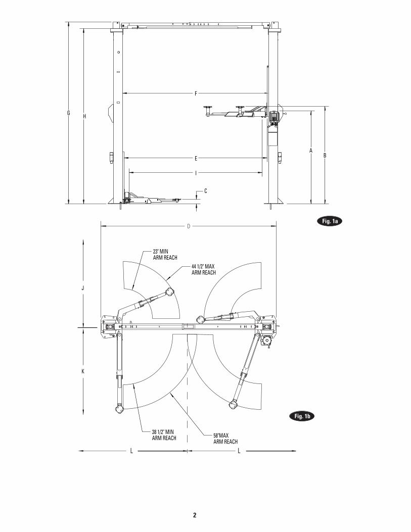
EXTENDED HEIGHT OVERALL (HOSE NOT INCLUDED) 166 1/2"
H FLOOR TO OVERHEAD SWITCH 137 3/4”
I DRIVE THRU CLEARANCE 104 1/2"
J MINIMUM TO NEAREST OBSTRUCTION 132" K MINIMUM TO NEAREST OBSTRUCTION 156"
DRIVE THRU CLEARANCE (NARROW) 98 1/2"
NOTES:1.) ALL HEIGHT DIMENSIONS ARE WITHOUT LEVELING SHIMS.2.) STANDARD HEIGHT LIFT SHOWN.3.) ** ANCHORING SYSTEM TESTED TO ANSI/ALI ALCTV:2006
L MINIMUM TO NEAREST OBSTRUCTION 72"
LIFT CAPACITY 10,000 LBS.
LIFTING SPEED (RISE TIME) APPROXIMATELY 45 SECONDS UNLOADED
MOTOR RATING OPTIONS 3 PHASE 208-230/460V 50-60 Hz 17/8.5-14/8 AMPS
SINGLE PHASE 208-230V 60Hz 16 AMPS
WEIGHT 1505 LBSMECHANICAL SAFETY LOCKS AUTOMATIC ALL POSITIONSMECHANICAL SAFETY RELEASE MANUAL ALL BOTH COLUMNS
HYDRAULIC SAFETY SYSTEM AUTOMATIC ALL POSITIONSCYLINDERS TWO, ONE PER COLUMNCARRIAGE BEARINGS EIGHT PER CARRIAGE, UHMW SYNCHRONIZATION EQUALIZATION CABLES MIN. BAY SIZE 12' X 24' VERIFY WITH SITE PLAN & SERVICE VEHICLES
APPROXIMATELY 51 SECONDS AT RATED CAPACITY
SINGLE PHASE 208-230V 50Hz 15 AMPS
MIN. LIFT HEIGHT W/ 1 3/4" ADAPTER
8 5/8"
FLOOR TO OVERHEAD SWITCH (HIGH RISE) 160 3/4”
MINIMUM CEILING HEIGHT
MINIMUM CEILING HEIGHT (EXTENDED HEIGHT)
144"
167"
SWING ARM RESTRAINTS AUTOMATIC ENGAGEMENT ABOVE 2 1/2"
1. Lift Location: Use architects plan when available to locate lift. Fig. 1a & Fig. 1b shows dimensions of a typical bay layout.
WARNING DO NOT install this lift in a pit or depression due to fire or explosion risks.
4
2. Latch Cable Guides: Install the latch cable conduit guide brackets to column using (1) 1/4”-20NC x 1” HHCS and 1/4”-20NC Flanged Locknut. It should go through hole nearest the edge as shown, Fig. 2. For extension please note paragraph 4.
Fig. 2
M10-1.5x20mm HHCS & M10-1.5 Flg. Locknut
1/2”-13x1-3/4” HHCS & 1/2” Flat Washer
1/2”-13 Nylon Locknut & 1/2” Flat Washer
1/2”-13x1-3/4” HHCS
1/2”-13 Nylon Locknut & 1/2” Flat Washer
Fig. 4
Note: Standard height installation continue to paragraph 6. For extended height continue to paragraph 3.
3. Male Connector (Extended Height): Attach male connectors to tops of cylinders before installing the extended height column extensions see Fig. 3.
4. Column Extension (Extended Height): Column extension is installed using (2) M10-1.5x20mm HHCS & (2) M10-1.5 Flg. Lock Nut on the inside of the lift column. Use (2) 1/2”-13x1-3/4” HHCS, (4) 1/2” Flat Wahser, and (2) 1/2”-13 Nylon Locknut on the outside of the column, Fig. 4. After the extension is installed install the latch cable guide on the outside of extension using (1) 1/4”-20NC x 1” HHCS and 1/4”-20NC Flanged Locknut, Fig. 4. Attach tie bar to column with (2) 1/2”-13x1-3/4” HHCS, (2) 1/2” Flat Washer, and (2) 1/2”-13 Nylon Locknut, Fig. 4.
3/8” NPT to 1/4” Tube Male Connector
Fig. 3
5
1/2”-13NC x 4-1/2” HHCS, 1/2” Flat Washer, &Cylinder Spacer
Place cylinder in this hole when using Extended Height High Rise Lift
Place cylinder in this hole when using T100288 Extended Height Kit only
5. Cylinder Install (Extended Height): With the extension installed the cylinder will be installed with (1) 1/2”-13x4-1/2” HHCS, (2) 1/2” Flat Washer, (2) 1/2” Cylinder Spacer, and (1) 1/2”-13 Nylon Locknut, Fig. 5. The lift carriage should now be manually raised to the bottom of the cylinder. The cylinder is then attached to the carriage using (1) 3/4”-16 Hex Nut and (1) 3/4”-16 Hex Jam Nut, Fig. 5.
Fig. 5
6
Use for narrow bay setting.
90° Elbow
Standard Cable Tie Off& 5/8" Nylon Insert Locknut
Remove Plug
NOTE: If more than 2 horse shoe shims are used at any of the column anchor bolts, pack non-shrink grout under the unsupported area of the column base. Insure shims are held tightly between the baseplate and floor after torquing anchors.
Shims(1/2" Max.)
Nut
Flat Washer
Anchor NOTE: Use rectangular shims at inside edge of baseplate. Use constructions adhesive or silicon cement to hold shim in place. INSURE shims are held tightly between base plate and floor after torquing anchors.
Fig. 6
6. Cylinder Fitting: Prior to standing up lift columns, install the 90 ° elbow fitting to the cylinder and equal-izer cable to the bottom of the carriage Fig 6. Remove plug from the top of the cylinders and install the ap-propriate fittings per Fig. 15a
CAUTION Over tightening will damage fitting resulting in fluid leakage.
7. Equalizer CablesA.) First, run a cable end up through the small hole in
the standard tie-off plate. Fig. 6.B) Push the cable up until the stud is out of the
carriage top opening.C) Run a nylon insert locknut onto the cable stud so
1/2” (13mm) of the stud extends out of the locknut.D) Pull the cable back down, Fig. 6.E) Run cable around the lower sheave, then up and
out of the top of the column.
8. Lift Setting: Position columns in bay using dimensions shown in Fig. 1a & Fig. 1b. Place column with power unit mounting bracket on vehicle passenger side of lift. Both column base plate backs must be square on center line of lift. Notches are cut into each base plate to indicate center line of lift. Use appropriate equipment to raise carriage to first latch position. Be sure locking latch is securely engaged.
9. Concrete and Anchoring: Drill (10) 3/4” dia. holes in concrete floor using holes in column base plate as a guide. See Fig. 8 for hole depth, hole spacing, and edge distance requirements.
Fig. 7
CAUTION DO NOT install on asphalt or other similar unstable surfaces. Columns are supported only by anchors in floor.
IMPORTANT Using the horse shoe shims provided, shim each column base until each column is plumb. If one column has to be elevated to match the plane of the other column, full size base shim plates should be used (Reference FA9116 Shim Kit). Recheck columns for plumb. Tighten anchor bolts to an installation torque of 110 ft-lbs. Shim thickness MUST NOT exceed 1/2” when using the 5-1/2” long anchors provided with the lift, Fig. 7. Adjust the column extensions plumb.
If anchors do not tighten to 110 ft-lbs. installation torque, replace concrete under each column base with a 4’ x 4’ x 6” thick 3000 PSI minimum concrete pad keyed under and flush with the top of existing floor. Let concrete cure before installing lifts and anchors.
7
Run nut down justbelow impact sectionof bolt. Drive anchorinto hole until nut and washer contact base.
Clean hole.Drill holes using 3/4” car-bide tipped masonry drill bit per ANSI B212.15-1994 (R2000)
Tighten nut withTorque wrench to 110 ft.-lbs.
CONCRETE AND ANCHORING REQUIREMENTS
STANDARD ANSI/ALI ALCTV IBC 2006, 2009, 2012 SEISMIC
Minimum Floor Thickness 4-1/4 INCHES
4-3/4 INCHES Extended Height Lift or Kit
5 INCHES 6 INCHES Varies by location consultwith your structural engineer
*The supplied concrete fasteners meet the criteria of the American National Standard “Automotive Lifts - Safety Requirements for Construction, Testing, and Validation” ANSI/ALI ALCTV-2011, and the lift owner is responsible for all charges related to any additional anchoring requirements as specified by local codes.
Contact customer service for further information at: 800.640.5438
Fig. 8
8
M10-1.5 x 20mm HHCS& Flanged Locknut
114" Standard108” Narrow Bay
11 3/4" Standard 7 3/4” Narrow
Hardware Detail For Overhead Assembly
1/4"-20NC x 2 3/4" HHCS
1/4" Lock Nut
Open Bar Side
1/4"-20NC x 3/4" HHCS
1/4" Lock Nut
Switch Box Side
1/4" FlatWasher
2 Spacers
HOLEDETAIL
Narrow BayStandard Bay
10a. Overhead Assembly: Fig. 10: Adjust overhead to appropriate dimension. Install (4) M10-1.5 x 20mm HHCS & M10-1.5 Flanged Locknuts, do not tighten. Slide Switch Box Fig. 9 over switch bar ensuring knock out holes face the power unit column. Use (2) 1/4”-20NC x 3/4” lg. HHCS, 1/4” Flat Washer, and 1/4”-20NC Nuts to mount switch box to overhead, see Fig. 10. 10b. Continued Overhead Assembly: For single phase lifts: Insert 1/4”-20NC x 2 3/4” HHCS through pivot hole in end of switch bar. Insert opposite end of bar through slot in switch mounting bracket. Then secure HHCS and Switch Bar to overhead as shown, Fig. 10, using (2) 3/4” spacers and 1/4”-20NC Locknut. Tighten Hex bolt leaving 1/16” gap between the spacer and the overhead assembly.
Fig. 10
Fig. 9
9
Use M10-1.5 x 20mmHHCS and Locknuts
Fig. 12
Place Actuator Here.A Small Amount Of Silicone SealantOn The Lower Part Of The ActuatorWill Help Hold It In Place.
Cradle Bar On Actuator
Actuator
Remove ScrewsAnd Cover
For three phase lifts: Remove Limit Switch cover, Fig. 11. Insert Actuator end of Switch Bar into slot located inside Limit Switch, Fig. 11. A small amount of silicone sealant on the lower part of the actuator will help hold it in place. Insert 1/4”-20NC x 2 3/4” HHCS through pivot hole in end of Switch Bar. Then secure HHCS and Switch Bar to overhead as shown, using (2) 3/4” spacers and 1/4”-20NC Locknut. Tighten Hex bolt leaving 1/16” gap between the spacer and the overhead assembly, Fig. 10. Replace limit switch cover.
11. Overhead Installation: Install overhead assembly to Mounting Bracket with (4) M10-1.5 x 20mm HHCS, and (4) M10-1.5 Flanged Locknut on both columns Fig. 12. Tighten bolts at center of overhead assembly.
12. Power Unit: First install a star washer onto all of the (4) 5/16”-18NC x 1-1/2” HHCS. This is very important for grounding. Put the (4) 5/16”-18NC x 1-1/2” HHCS thru holes in power unit bracket, Fig. 13. Mount unit with motor up to column bracket and install (4) 5/16” star washers and 5/16” Nuts. Install and hand tighten fitting to pump until O-ring is seated. Continue to tighten the locknut until the nut and washer bottom out against the pump manifold. NOTE: You may still be able to rotate the fitting. This is acceptable unless there is seepage at the O-ring. If so, slightly tighten the locknut.
CAUTION Over tightening locknut may tear O-ring or distort threads in pump manifold outlet.
13. Hoses: Clean adapters and hose. Inspect all threads for damage and hose ends to be sure they are crimped, Fig. 14. Install hose and hose clamps, Fig. 15a, Fig. 15b, Fig. 15c, & Fig. 19a.
Flared Fittings Tightening Procedure1. Screw the fittings together finger tight. Then, using
the proper size wrench, rotate the fitting 2-1/2 hex flats.
IMPORTANT Flare seat MUST NOT rotate when tightening. Only the nut should turn.
2. Back the fitting off one full turn.3. Again tighten the fittings finger tight; then using a
wrench, rotate the fitting 2-1/2 hex flats. This will complete the tightening procedure and develop a pressure tight seal.
CAUTION Over tightening will damage fitting resulting in fluid leakage.
Fig. 11
10
OverheadHose
Fitting
Fitting
Return Line
On all four bolts, place(2) 5/16" Star Washers
Fill Breather Cap
Use (4 5/16"-18NC x1-1/2" lg. HHCS and Nuts
Fig. 11
Fig. 14
4. Place the assembled “T” fitting behind the cylinder and connect the hoses to the two cylinder ends and the Power Unit.
5. Take up the slack in the Power Unit side cylinder hose and wire tie the “T” fitting tightly to the power unit side cylinder.
6. Secure each hose as needed.
7. Run return line from elbow Pc. (8) to tee Pc. (9). The return line then runs outside of column down and connects to the power unit, Fig. 15a.
NOTE: Overhead hose goes over top end of overhead assembly, Fig. 15a, Fig. 15c, Fig. 19a, & Fig. 19b.
14
10
FRONT
Hose runs down approach side to
cylinder on left column.
3
6
8
9
7
Wire ties secure hose to cylinder.
5
2Adapter & Hose Installation (Standard Height)
1. Before installing the hoses into the lift, attach the Overhead hose Pc. (3) and Cylinder hose Pc. (4) to the “T” fitting Pc. (6) as shown in Figure 15c.
2. Route the assembled hose through the overhead but do not attach to either cylinder.
3. Route the Power Unit hose Pc. (5) through the column hole and attach it to the “T” fitting.
IMPORTANT : Before you connect the power unit hose you must tuck the hoses and union tee behind the cylinder to give you room to complete installation, Fig 15c.
ITEM QTY. DESCRIPTION 1 1 Power Unit Side Cylinder 2 1 Slave Side Cylinder 3 1 Overhead Hose 4 1 Cylinder Hose 5 1 Power Unit Hose 6 1 3/8” Branch Tee 7 1 Return Line 8 1 1/4” Elbow 9 1 1/4” Branch Tee 10 2 Hose Clamps 2 M10-1.5 x 20mm HHCS 2 M10-1.5 Flanged Locknuts
Fig. 15a
Fig. 13
11
12
98
FRONT
Hose runs down approach side to
cylinder on left column.
3
5
77
6
Wire ties secure hose to cylinder.
4
Adapter & Hose Installation (Extended Height)
1. Before installing the hoses into the lift, attach the Overhead hose Pc. (3) and Cylinder hose Pc. (4) to the “T” fitting Pc. (6) as shown in Figure 15c.
2. Route the assembled hose through the overhead but do not attach to either cylinder.
3. Route the Power Unit hose Pc. (5) through the column hole and attach it to the “T” fitting.
IMPORTANT : Before you connect the power unit hose you must tuck the hoses and union tee behind the cylinder to give you room to complete installation, Fig 15c.
4. Place the assembled “T” fitting behind the cylinder and connect the hoses to the two cylinder ends and the Power Unit.
5. Take up the slack in the Power Unit side cylinder hose and wire tie the “T” fitting tightly to the power unit side cylinder.
6. Secure each hose as needed.
7. Run return line from Pc. (8) to tee Pc. (9) on both cylinders. The return line then runs outside of column down and connects to the power unit, Fig. 15b.
NOTE: Overhead hose goes over top end of overhead assembly, Fig. 15b, Fig. 15c, Fig. 19a, & Fig. 19b. ITEM QTY. DESCRIPTION
1 1 Power Unit Side Cylinder 2 1 Slave Side Cylinder 3 1 Overhead Hose 4 1 Cylinder Hose 5 1 Power Unit Hose 6 1 3/8” Branch Tee 7 1 Return Line 8 2 3/8” to 1/4” Male Connector 9 1 1/4” Branch Tee 10 2 Hose Clamps 2 M10-1.5 x 20mm HHCS 2 M10-1.5 Flanged Locknuts
Assemble These3 Items BeforeYou Route ThemInside The LiftAssembly
Hydraulic HoseTo Passenger SideCylinder
Hydraulic HoseTo Power Unit SideCylinder
Hydraulic HoseTo Power Unit Side
Cylinder
Union Tee
Union Tee
Wire Tie Union TeeAnd Hydraulic hosesbehind the Cylinder
IMPORTANT
Fig. 15c
13
14. Equalizing CablesA) Refer to Fig. 17 for the general cable arrangement.B) Run cable from paragraph 7 around overhead
sheave and across and down to the opposite carriage, Fig. 17. Install sheave cover, Fig. 16.
C) Fasten the cable end to the carriage upper tie-off bracket, Fig. 18. Tighten the locknut enough to apply light tension to the cable.
D) Adjust the tension of both cables during the final adjustments in Paragraph 24.
1st Cable2nd Cable
Upper Sheaves
Lower Sheaves
Narrow Cable Tie Off
Standard Cable Tie Off
Upper Cable Tie Off& 5/8" Nylon Insert Locknut
Sheave Cover
Fig. 17
Fig. 16
Fig. 18
14
15. Locking Latch CableA) Slip loop end of cable over end of shoulder screw
on right side latch control plate, Fig. 20.B) Feed the other end of the cable through the latch
cable sheave slot making sure that the cable is running under the bottom side of the latch cable sheave and inside the right column, Fig. 20.
C) Attach latch cable conduit guide brackets to overhead as shown, Fig. 19a & Fig. 19b. Always use the holes on the approach side of the lift. HHCS should be in hole nearest the center of the overhead, Fig. 19b.
D) Route cable up inside column and through the latch cable guide, Fig. 19a & Fig. 21.
IMPORTANT Using wire ties provided, tie off hydraulic hose snug to cylinders to keep hose away from equalizing cable, Fig. 15a.
E) Continue routing cable to the left column latch cable guide, Fig. 19a & Fig. 21, routing the cable through the left column latch cable guide, Fig. 19a.
use two holes on approachside of extension to attach bracket. Always put HHCS through hole
closest to center of overhead.
Fig. 19b
F) Bring the cable down inside the left column and feed the end of the cable through the lower latch cable sheave slot so that the cable is now back outside the column, Fig. 22.
G) Route cable under the bottom side of the latch cable sheave, Fig. 22.
H) At this point you MUST install the latch handle, jam nut, and right column latch cover Fig. 20 & Fig. 23. Install latch handle ball, Fig. 23.
I) Insert cable in cable clamp along one side, loop around shoulder screw and back down, inserting cable along other side of cable clamp, Fig. 22. Place top back on clamp, barely tightening.
J) Next, pull the control plate down, Fig. 21 & Fig. 22, to eliminate any clearance between the control plate slot and the latch dog pin, Fig. 21.
K) Using Pliers, pull cable tight and secure the clamp close to the shoulder screw. Tighten clamp.
15
(2) 3/8" Retaining Rings
Latch Cable Sheave
Shoulder Bolt
Install Latch Handle using a 3/8"hex jam nut to lock in place. Theninstall flat washers and slot cover.
(3) 3/8” Flat Washers
Slot Cover
Shoulder Bolt
Cable Clamp
Feed cable up through CableClamp, loop over end of shoulder bolt and feed backdown through Cable Clamp.
(2) 3/8" RetainingRings
Latch Cable Sheave
Fig. 22
5/16-18NC x 3/8" lg. PHMS
Latch handle MUST be positioned at the top of the latch control cover.
Connect supply to wires in box as per Fig. 20. Attach ground wire to screws provided.
Attach ground wire here.
208-230V 60Hz Single Phase
Attach black wire to one motor wire. Attach white
wire to one motor wire.
Black Green
White
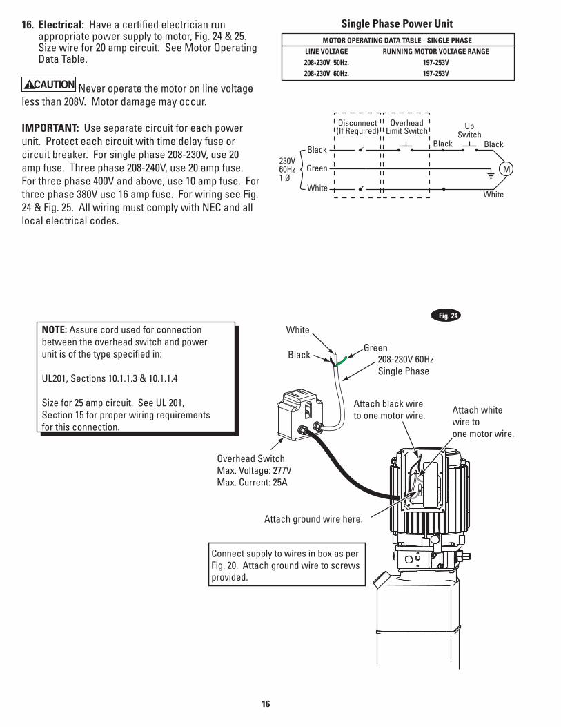
Single Phase Power UnitMOTOR OPERATING DATA TABLE - SINGLE PHASE
LINE VOLTAGE RUNNING MOTOR VOLTAGE RANGE 208-230V 50Hz. 197-253V 208-230V 60Hz. 197-253V
NOTE: Assure cord used for connectionbetween the overhead switch and powerunit is of the type specified in:
UL201, Sections 10.1.1.3 & 10.1.1.4
Size for 25 amp circuit. See UL 201, Section 15 for proper wiring requirementsfor this connection.
M230V60Hz1 Ø
Black
Green
White
OverheadLimit Switch Up
Switch
White
Disconnect(If Required)
Black Black
16. Electrical: Have a certified electrician run appropriate power supply to motor, Fig. 24 & 25. Size wire for 20 amp circuit. See Motor Operating Data Table.
CAUTION Never operate the motor on line voltage less than 208V. Motor damage may occur.
IMPORTANT: Use separate circuit for each power unit. Protect each circuit with time delay fuse or circuit breaker. For single phase 208-230V, use 20 amp fuse. Three phase 208-240V, use 20 amp fuse. For three phase 400V and above, use 10 amp fuse. For three phase 380V use 16 amp fuse. For wiring see Fig. 24 & Fig. 25. All wiring must comply with NEC and all local electrical codes.
Fig. 24
17
T7T1
T8T2
T9T3
T4
T5
T6
L1
L2
L3
T7 T4T1L1
T8 T5T2L2
T9 T6T3L3
T1
T2
T3
U2
V2
W2
W1
V1
U1
208-240V50/60Hz. 3Ø
440-480V 50/60 Hz. 3Ø380-400V 50 Hz. 3Ø
575V 60 Hz. 3Ø
L1
PE
L2L3
135
246 MOTOR
135
246
OVERHEAD SWITCH(WHERE APPLICABLE)
DRUMSWITCH
3 PhaseSupply
Three Phase Power UnitMOTOR OPERATING DATA TABLE - THREE PHASE
LINE VOLTAGE RUNNING MOTOR VOLTAGE RANGE 208-240V 50/60Hz. 197-253V 400V 50Hz. 360-440V 440-480V 50/60Hz. 396V-528V 575V 60Hz. 518V-632V
(4) M5 x 45 PHMS, Plated
(4) M5 x 10 PHMS, PlatedCapacitor Box To Power Unit
Drum SwitchAnd Cover
Re-seal BetweenBox And SpacerWith SiliconeSealer
CapacitorBox
Gasket
3 Phase
Fig. 25
18Fig. 26a
InstallationPinch Point
Keep HandsAbove Groove
CAUTION 17. Oil Filling & Bleeding: Use Dexron III ATF, or Hydraulic Fluid that meets ISO 32 specifications. Remove fill-breather cap, Fig. 13. Pour in (8) quarts of fluid. Start unit, raise lift to full rise several times until lift operates smoothly.
CAUTION If fill-breather cap is lost or broken, order replacement. Reservoir must be vented.
18. Overhead switch: Check overhead switch assembly to assure that switch bar is depressing switch plunger sufficiently to actuate the switch. The overhead switch is wired normally open, see Fig. 24 & Fig. 25. Lift will not operate until weight of switch bar is depressing switch plunger. Verify that Power Unit stops working when switch bar is raised, and re-starts when the bar is released.
19. Arms & Restraints: Before installing arms, raise carriages to a convenient height. Grease swivel arm pins and holes with Lithium grease. Slide arm into yoke, Fig. 26a. Install 1-3/4” diameter arm pin(s) and arm stop, Fig. 26a.
Note: Arm stop will be required on the drive in side of the power unit side. Install at same time as arm pin, Fig. 26b. Notice the orientation of arm stop in Fig. 26c.
After installing arms and pins, install arm Restraint Gears as follows: Install Restraint Gear onto arm clevis, as shown, Fig. 27a. Ensure side of gear marked TOP is facing upward, Fig. 27a.
NOTE: TOP is stamped on top side of gear. You may need to pull up on the pin to allow enough room to install Restraint Gear.
Arms With 3 Holes In Bearing Bars: Then, install the (2) 3/8”-16NC x 1-1/2” Lg. HHCS ((8) total for all (4) arms) into the gear and arm. Reference Fig. 25b and Fig. 28.
Torque the Restraint Gear bolts to 30-34 ft.-lbs.
NOTE: To check operation of arm restraints, raise carriage 1” min. from full down position. Pull up on pin and adjust arms to desired position. To engage restraint, let pin-ring down allowing gear teeth to mesh together. It may be necessary to rotate arm slightly to engage gear teeth.
NOTE: Pin, Spring, & Gear Block are all pre-assem-bled.
Arm Stop
Fig. 26b
19
NOTE beveled gear orientation
TOP will be marked on top side of restraint gear
NOTE: Once arm is installed in yoke, pull up actuator pin and swing arm fully around, being sure that the Restraint Gear and Gear Block always stay aligned. If they do not stay aligned, remove restraint gear and install in the opposite position.
Fig. 27b
Use holes marked “A” for Right Frontand Left Rear.
A
A
Use holes marked “A” for Left Frontand Right Rear.
A A
Fig. 28
Fig. 27a
Note: Location and Orientation of Arm Stop
Fig. 26c
20
5/16”-18NC x 3/8” PHMS
M8 x 35mm Socket Bolt
20. Rubber Bumper Installation: Install rubber bumpers inside of both sides of lift using (2) M8 x 35mm socket bolts, Fig. 29.
Fig. 29
Fig. 30
21. Exterior Adapters: Install adapter bracket to outside of each column using (2) 5/16”-18NC x 3/8” PHMS. Then, add adapters to the bracket as shown, Fig. 30.
NOTE: Figure shown with truck adapter accessory.
21
Raise Lift Off Latches
Actuate To Release Latches
Pinch PointCAUTION
NP2
66 R
ev C
Raise Lift Off
Latches
Actuate To Release
Latches
P
inch Point
CAUTION
NP26
6 Re
v C
Fig. 33
22. Latch Cable Adjustment: A) Check to make sure the latch will properly engage
and disengage. Slowly release the latch handle. A 1/8” gap between the top of the latch dog and the column is allowable, Fig. 31.
B) When raising, listen to latches to be sure that both latch dogs fall into latch slots. If they do not, loosen clamp and adjust tension as necessary.
C) Install left latch cover using 5/16-18NC x 3/8” lg PHMS.
23. Pressure Test: Run lift to full rise and keep motor running for 5 seconds. Stop and check all hose connections. Tighten or reseal if required. Repeat air bleeding of cylinders.
24. Equalizer Cable Adjustment: Raise lift to check equalizer cable tension. Below carriage, grasp adjacent cables between thumb and forefinger, with about 15 lbs. effort you should just pull the cables together, Fig. 32. Adjust at upper tie-offs Fig. 18.
Fig. 31
Fig. 32
22
NOTES
23
NOTES
Forward Lift996 Industrial DriveMadison, IN. 47250