Please read this manual and follow its instructions carefully. To emphasize special information, the symbol and words WARNING, CAUTION and NOTE have special meanings. Pay special attention to the messages highlighted by these signal words.
WARNING Indicates potential hazard that could result in death or injury. Caution Indicates potential hazard that could result in vehicle damage.
Note Indicates special information to make maintenance easier or Instructions clearer.
Caution Installation of this SUZUKI ORIGINAL ACCESSORY must be performed only by an authorized SUZUKI dealer who has the proper tools and experience to do the job correctly.
Caution – Preparation before Installation
a) Park the motorcycle steady in a safe place. b) Keep the ignition key removed. c) Be sure not to damage any vehicle part. d) Check that all the parts are contained in the kit as listed in “Contents” section. e) Disconnect the battery negative pole
1. Installation
BURGMAN 125 / 200 (UH 125 / 200) a) Dismount the front leg shield including the headlights (follow chapter 8 of the service manual). b) Insert deeply the 18-pin harness connector in the alarm unit up to the security catch is clicking. c) Adjust the wire length by using delivered tie raps as shown in pict.1 d) Clean carefully the unit mounting area (pict. 2) and the bottom side of the alarm unit with a suitable cleaner. e) Mount the alarm unit with the bi-adhesive tape as indicated in pict. 1 and press them for a few seconds. f) Connect the 1-pin connector (pict. 3 A) (+12V) to the plug&play harness counterpart. g) Identify the 13-pin turn indicators connector (yellow plug pict. 3 B). Interpose the plug&play harness counterparts h) Identify the “SIDE STAND RELAY” (wire colour: green; orange/yellow; orange/black; orange/yellow) (pict. 4 C) and interpose the plug&play
harness counterparts. i) Place the LED as indicated in picture 5 D. j) Connect the LED 2-pin connector to the plug&play harness counterpart. k) Route the wires of the harness and secure them with tie raps “5”. l) Remount the front leg shield and the negative battery pole. m) Check and test the system (point 2).
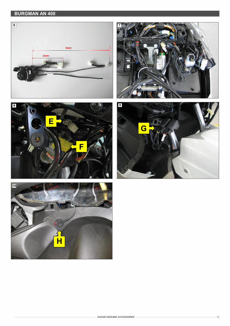
BURGMAN 400 (AN 400) a) Dismount the wind shield, the meter panel; front leg shield including the headlights (follow chapter 9D of the service manual). b) Insert deeply the 18-pin harness connector in the alarm unit up to the security catch is clicking. c) Adjust the wire length by using delivered tie raps as shown in pict.6 d) Clean carefully the unit mounting area (pict. 7) and the bottom side of the alarm unit with a suitable cleaner. e) Mount the alarm unit with the bi-adhesive tape as indicated in pict. 7 and press them for a few seconds. f) Connect the 1-pin connector (pict. 8 E) (+12V) to the plug&play harness counterpart. g) Identify the 13-pin turn indicators connector (yellow plug pict. 8 F). Interpose the plug&play harness counterparts h) Identify the “SAFETY RELAY” (wire colour: yellow/green; yellow/black; white/black; black/white) (pict. 9 G) and interpose the plug&play harness
counterparts. i) Place the LED as indicated in picture 10 H. j) Route the wires of the harness and secure them with tie raps “5”. k) Remount the wind shield, the meter panel; front leg shield and connect the LED 2-pin connector to the plug&play harness counterpart during
remounting. l) Reconnect the negative battery pole. m) Check and test the system (point 2).
Important
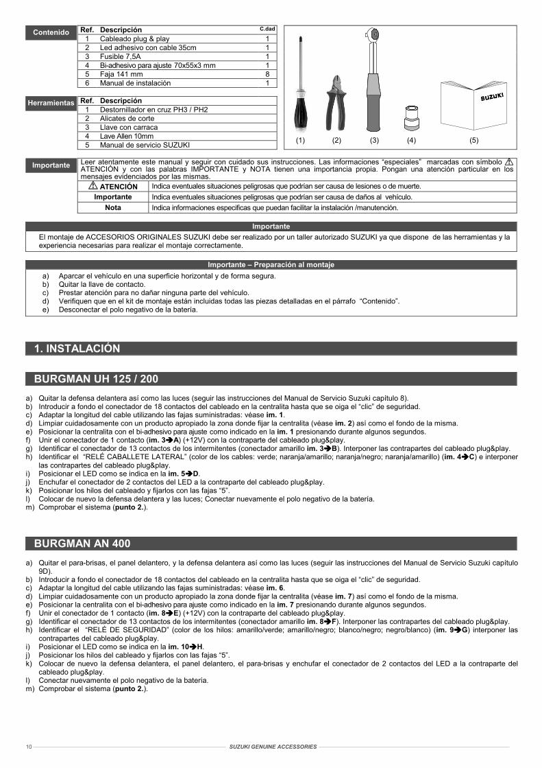
Contents
Tools SUZUKI
SUZUKI
SUZUKI
SUZUKI
(1) (2) (3) (4) (5)
SUZUKI GENUINE ACCES
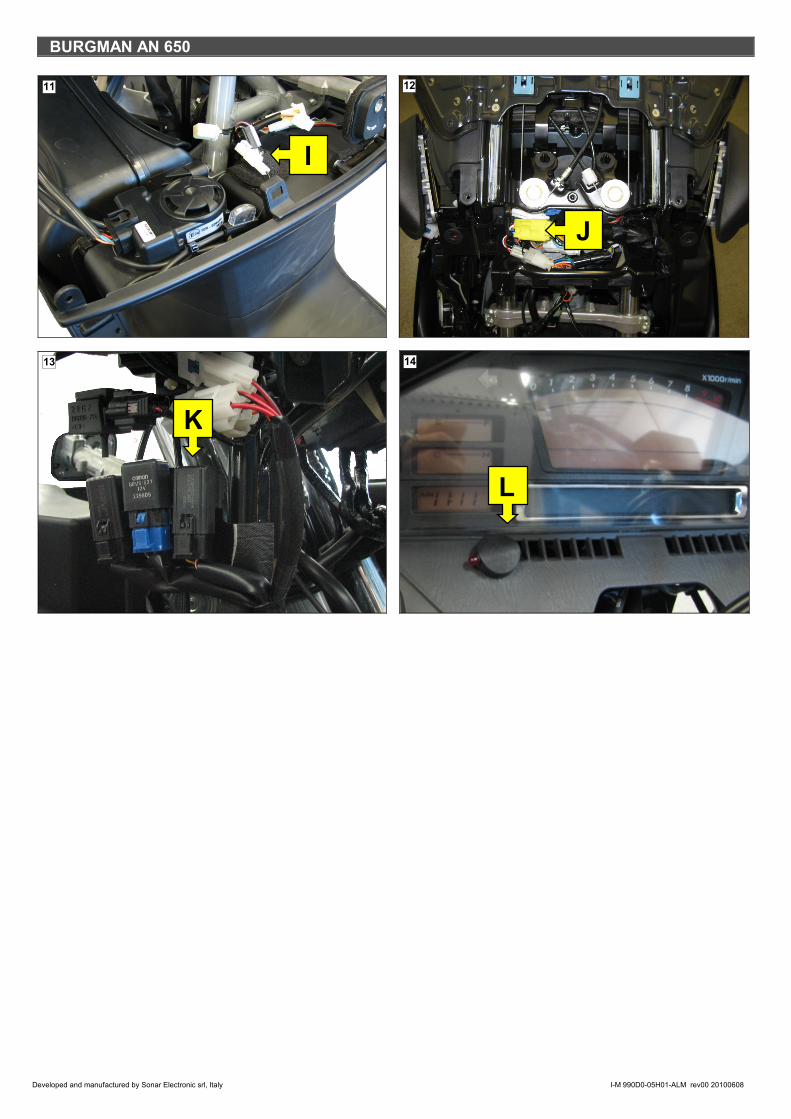
BURGMAN 650 (AN 650) a) Dismount the wind shield, the front panel; the front leg shield including the headlights and the meter front panel (follow chapter 9 of the service
manual). b) Insert deeply the 18-pin harness connector in the alarm unit up to the security catch is clicking. c) Clean carefully the unit mounting area (pict. 11) and the bottom side of the alarm unit with a suitable cleaner. d) Mount the alarm unit with the bi-adhesive tape as indicated in pict. 11 and press them for a few seconds. e) Connect the 1-pin connector (pict. 11 I) (+12V) to the plug&play harness counterpart. f) Identify the 13-pin turn indicators connector (yellow plug pict. 12 J). Interpose the plug&play harness counterparts g) Identify the “SIDE STAND RELAY” (wire colour: green; orange/white; yellow/black; black/white) (pict. 13 K) and interpose the plug&play harness
counterparts. h) Place the LED as indicated in picture 14 L and connect the LED 2-pin connector to the plug&play harness counterpart. i) Route the wires of the harness and secure them with tie raps “5”. j) Remount the front meter panel, the front leg shield, the front panel and the wind shield and reconnect the negative battery pole. k) Check and test the system (point 2).
2. SYSTEM TEST
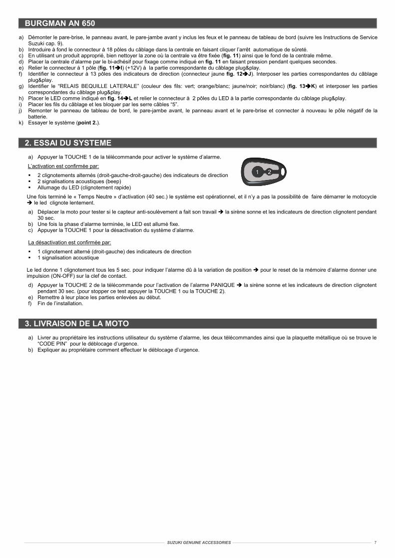
a) To arm the system push once BUTTON 1 of the remote control.
Arming is confirmed by:
2 turn indicators alternated flashing (right-left-right-left) 2 acoustic signals (bleep) LED turns on (quick flash)
The system is operating after 40 sec. «Standby Time»: the motorbike cannot b
b) Move the motorbike to test that the movement sensor is operating siren c) At the end of the alarm phase the LED is steady ON. d) To disarm the system push BUTTON 1 of the remote control.
Disarming is confirmed by:
1 turn indicators alternated flashing (right-left) 1 acoustic signal
LED gives 1 flash every 5 sec. to confirm an alarm due to a position variatioignition key.
e) To activate the PANIC alarm push once BUTTON 2 of the remote control stop this test push or BUTTON 1 or BUTTON 2).
f) Re-assemble the parts previously removed. g) End of installation.
3. MOTORBIKE DELIVERY
a) Deliver to the owner the alarm system user instruction and the two remote c“PIN CODE” is printed.
b) Explain to the owner the releasing emergency procedure.
SORIES 3
e started Led flashes slowly
sounds and turn indicators are flashing during 30 sec.
n to reset the alarm memory give an impulse (ON-OFF) on the
the siren sounds and turn indicators are flashing during 30 sec. (to
ontrols together with the metal plate where the releasing emergency
SUZUKI GENUINE ACCESSORIES 4
Ref. Beschreibung Anz.1 Kabel plug & play 1 2 Selbstklebende Led mit Kabel 35cm 1 3 Sicherung 7,5A 1 4 Doppelseitiges Klebeband 70x55x3 mm 1 5 Kabelbinder 141mm 8
Bitte lesen Sie diese Anleitung gut durch und befolgen Sie die darin enthaltenen Anweisungen. Die durch das Symbol ACHTUNG, sowie WICHTIG und HINWEIS gekennzeichneten Angaben haben eine besondere Bedeutung. Den mit den oben genannten Symbolen/Wörtern markierten Anweisungen sollte daher erhöhte Aufmerksamkeit geschenkt werden.
ACHTUNG Weist auf mögliche Gefahren hin, die zu Verletzungen oder zum Tod führen können. Wichtig Weist auf mögliche Gefahren hin, durch die das Fahrzeug beschädigt werden könnte.
Hinweis Liefert spezifische Informationen zur Erleichterung der Installations- oder Wartungsarbeiten.
Wichtig Montage dieses SUZUKI ORIGINAL ZUBEHÖRS darf nur durch einen authorisierten SUZUKI Händler durchgeführt werden.
Wichtig – Vorbereitung zur Montage
a) Parken Sie das Fahrzeug an einem sicheren Ort und in stabiler Position. b) Ziehen Sie den Zündschlüssel ab. c) Achten Sie darauf, dass beim Einbau keine Fahrzeugteile beschädigt werden. d) Überprüfen Sie, dass das Montageset alle unter dem Punkt „Inhalt“ aufgelisteten Teile enthält. e) Den Minuspol der Batterie abklemmen.
1. INSTALLATION
BURGMAN UH 125 / 200 a) Die vordere Verkleidung einschließlich der Beleuchtung entfernen (gemäß Kapitel 8 des Werkstatthandbuchs). b) Den 18-Wege-Stecker des Anschlusskabels komplett in die Alarmzentrale einstecken und die Sicherheitssperre einrasten lassen. c) Die Länge der Kabel mit Hilfe der mitgelieferten Kabelbinder anpassen, siehe Abb. 1. d) Die gezeigte Stelle (Abb. 2) und die Unterseite der Alarmzentrale gründlich mit einem geeigneten Produkt reinigen. e) Die Alarmzentrale mit dem doppelseitigen Klebeband gemäß Abb. 1 positionieren und einige Sekunden lang festdrücken. f) Den 1-Weg-Stecker (Abb. 3 A) (+12V) mit dem Plug&Play-Kabelende verbinden. g) Den 13-Wege-Stecker der Fahrtrichtungsanzeiger ausfindig machen (gelber Stecker Abb. 3 B) und die Plug&Play-Kabelenden dazwischen
klemmen. h) Das „RELAIS SEITENSTÄNDER“ suchen (Farbe der Drähte: grün; orange/gelb; orange/schwarz; orange/gelb) (Abb. 4 C) und die Plug&Play-
Kabelenden dazwischen klemmen. i) Die LED gemäß Abb. 5 D positionieren. j) Den 2-Wege-Stecker der LED mit dem Plug&Play-Kabelende verbinden. k) Die Drähte des Anschlusskabels positionieren und mit den Kabelbindern „5“ befestigen. l) Erneut die vordere Verkleidung einschließlich der Beleuchtung anbringen und den Minuspol der Batterie anschließen. m) Das System testen (Punkt 2).
BURGMAN AN 400 a) Die Windschutzscheibe, Instrumententafel und vordere Verkleidung einschließlich Beleuchtung entfernen (gemäß Kapitel 9D des
Werkstatthandbuchs). b) Den 18-Wege-Stecker des Anschlusskabels komplett in die Alarmzentrale einstecken und die Sicherheitssperre einrasten lassen. c) Die Länge der Kabel mit Hilfe der mitgelieferten Kabelbinder anpassen, siehe Abb. 6. d) Die gezeigte Stelle (Abb. 7) und die Unterseite der Alarmzentrale gründlich mit einem geeigneten Produkt reinigen. e) Die Alarmzentrale mit dem doppelseitigen Klebeband gemäß Abb. 7 positionieren und einige Sekunden lang festdrücken. f) Den 1-Weg-Stecker (Abb. 8 E) (+12V) mit dem Plug&Play-Kabelende verbinden. g) Den 13-Wege-Stecker der Fahrtrichtungsanzeiger ausfindig machen (gelber Stecker Abb. 8 F) und die Plug&Play-Kabelenden dazwischen
klemmen. h) Das „SICHERHEITSRELAIS“ suchen (Farbe der Drähte: gelb/grün; gelb/schwarz; weiß/schwarz; schwarz/weiß) (Abb. 9 G) und die Plug&Play-
Kabelenden dazwischen klemmen. i) Die LED gemäß Abb. 10 H positionieren. j) Die Drähte des Anschlusskabels positionieren und mit den Kabelbindern „5“ befestigen. k) Erneut die Windschutzscheibe, Instrumententafel und vordere Verkleidung anbringen und den 2-Wege-Stecker der LED mit dem Plug&Play-
Kabelende verbinden. l) Den Minuspol der Batterie erneut anschließen. m) Das System testen (Punkt 2).
Wichtig
SUZUKI
SUZUKI
SUZUKI
SUZUKI
(1) (2) (3) (4) (5)
Inhalt
Werkzeuge
SUZUKI GENUINE ACCESSORIES
BURGMAN AN 650 a) Die Windschutzscheibe, Fronttafel, vordere Verkleidung einschließlich Beleuchtung und Instrumententafel entfernen (gemäß Kapitel 9 des
Werkstatthandbuchs). b) Den 18-Wege-Stecker des Anschlusskabels komplett in die Alarmzentrale einstecken und die Sicherheitssperre einrasten lassen. c) Die gezeigte Stelle (Abb. 11) und die Unterseite der Alarmzentrale gründlich mit einem geeigneten Produkt reinigen. d) Die Alarmzentrale mit dem doppelseitigen Klebeband gemäß Abb. 11 positionieren und einige Sekunden lang festdrücken. e) Den 1-Weg-Stecker (Abb. 11 I) (+12V) mit dem Plug&Play-Kabelende verbinden. f) Den 13-Wege-Stecker der Fahrtrichtungsanzeiger ausfindig machen (gelber Stecker Abb. 12 J) und die Plug&Play-Kabelenden dazwischen
klemmen. g) Das „RELAIS SEITENSTÄNDER“ suchen (Farbe der Drähte: grün; orange/weiß; gelb/schwarz; schwarz/weiß) (Abb. 13 K) und die Plug&Play-
Kabelenden dazwischen klemmen. h) Die LED gemäß Abb. 14 L positionieren und den 2-Wege-Stecker der LED mit dem Plug&Play-Kabelende verbinden. i) Die Drähte des Anschlusskabels positionieren und mit den Kabelbindern „5“ befestigen. j) Erneut die Instrumententafel, vordere Verkleidung, Fronttafel und Windschutzscheibe anbringen und den Minuspol der Batterie anschließen. k) Das System testen (Punkt 2).
2. PRÜFUNG DES SYSTEMS
a) Zur Aktivierung des Alarmsystems die TASTE 1 auf der Fernbedienung drücken.
Die Aktivierung wird bestätigt durch:
Zweifaches Blinken der Fahrtrichtungsanzeiger (rechts-links-rechts-links) Zwei akustische Signale (Piepton)Einschalten der LED (schnelles Blinken)
Nach Ablauf der Aktivierungszeit (40 Sek.) ist das System eingeschaltet und das Motorrad k
b) Das Kraftrad verschieben, um zu überprüfen, ob der Bewegungssensor korrekt funktionblinken 30 Sek. lang.
c) Nach der Alarmphase leuchtet die LED weiter. d) Zur Deaktivierung des Alarmsystems die TASTE 1 drücken.
Die Deaktivierung wird bestätigt durch:
Einmaliges Blinken der Fahrtrichtungsanzeiger (rechts-links) 1 akustisches Signal
Die LED leuchtet alle 5 Sek. lang einmal auf, um anzuzeigen, dass ein Alarm infolge einer Pdes Alarmspeichers einen Impuls mit dem Zündschlüssel geben (ON-OFF).
e) Zur Aktivierung des PANIK-Alarms die TASTE 2 der Fernbedienung drücken die SSek. lang (zur Unterbrechung des Tests die TASTE 1 oder TASTE 2 drücken).
f) Die vorher ausgebauten Teile erneut anbringen. g) Die Installation ist nun abgeschlossen.
3. ÜBERGABE DES MOTORRADS
a) Dem Eigentümer die Bedienungsanleitung des Alarmsystems und die beiden Funksteuedie Notentriegelung aushändigen.
b) Dem Eigentümer die Prozedur der Notentriegelung erklären.
5
ann nicht mehr gestartet werden LED blinkt langsam.
iert die Sirene ertönt und die Fahrtrichtungsanzeiger
ositionsänderung ausgelöst wurde zum Rückstellen
irene ertönt und die Fahrtrichtungsanzeiger blinken 30
rungen, sowie das Metallschild mit dem „PIN-CODE“ für
SUZUKI GENUINE ACCESSORIES 6
Réf. Désignation Q.tité1 Câblage plug & play 1 2 Led adhésif câblé cm.35 1 3 Fusible 7,5A 1 4 Bi-adhésif pour fixage 70x55x3 mm 1 5 Serre câble 141 mm 8
Lire ces instructions de montage et les suivre avec attention. Les informations spéciales indiquées par le symbole ATTENTION et par les mots IMPORTANT et REMARQUE ont une importance particulière. Prêter une grande attention aux messages mis en évidence par le symbole/mots ci-dessus.
ATTENTION Indique de possibles situations dangereuses pouvant causer ou des lésions ou la mort. Important Indique de possibles situations dangereuses pouvant causer des dommages à la moto.
Remarque Indique des informations spécifiques pouvant faciliter l’installation/manutention.
Important L’installation des ACCESSOIRES D’ORIGINE SUZUKI doit être effectuée par un concessionnaire SUZUKI ayant les outils appropriés et l’expérience adéquate pour pouvoir faire l’installation correctement.
Important – Opérations avant le montage
a) Garer le motocycle en lieu sûr et à surface plate. b) Enlever la clef de contact. c) Faites bien attention à ne pas endommager nulle part le motocycle. d) Assurez-vous que le kit montage inclue bien toutes les pièces détaillées au par. “Contenu”. e) Déconnectez le pôle négatif de la batterie.
1. INSTALLATION
BURGMAN UH 125 / 200 a) Démonter le carénage avant y inclus les feux (suivre les Instructions de Service Suzuki cap. 8). b) Introduire à fond le connecteur à 18 pôles du câblage dans la centrale en faisant cliquer l’arrêt automatique de sûreté. c) Adapter la longueur des fils en utilisant les serre câbles fournies, comme indiqué en fig. 1. d) En utilisant un produit approprié, bien nettoyer la zone où la centrale va être fixée (fig. 2) ainsi que le fond de la centrale même. e) Placer la centrale d’alarme par le bi-adhésif pour fixage comme indiqué en fig. 1 en faisant pression pendant quelques secondes. f) Relier le connecteur à 1 pôle (fig. 3 A) (+12V) à la partie correspondante du câblage plug&play. g) Identifier le connecteur à 13 pôles des indicateurs de direction (connecteur jaune fig. 3 B). Interposer les parties correspondantes du câblage
plug&play. h) Identifier le “RELAIS BEQUILLE LATERALE” (couleur des fils: vert; orange/jaune; orange/noir; orange/jaune) (fig. 4 C) et interposer les parties
correspondantes du câblage plug&play. i) Placer le LED comme indiqué en fig. 5 D. j) Relier le connecteur à 2 pôles du LED à la partie correspondante du câblage plug&play. k) Placer les fils du câblage et les bloquer par les serre câbles “5”. l) Remonter le carénage avant ainsi que les feux et connecter à nouveau le pôle négatif de la batterie. m) Essayer le système (point 2.).
BURGMAN AN 400 a) Démonter le pare-brise, le panneau de tableau de bord et le carénage avant y inclus les feux (suivre les Instructions de Service Suzuki cap. 9D). b) Introduire à fond le connecteur à 18 pôles du câblage dans la centrale en faisant cliquer l’arrêt automatique de sûreté. c) Adapter la longueur des fils en utilisant les serre câbles fournies, comme indiqué en fig. 6. d) En utilisant un produit approprié, bien nettoyer la zone où la centrale va être fixée (fig. 7) ainsi que le fond de la centrale même. e) Placer la centrale d’alarme par le bi-adhésif pour fixage comme indiqué en fig. 7 en faisant pression pendant quelques secondes. f) Relier le connecteur à 1 pôle (fig. 8 E) (+12V) à la partie correspondante du câblage plug&play. g) Identifier le connecteur à 13 pôles des indicateurs de direction (connecteur jaune fig. 8 F). Interposer les parties correspondantes du câblage
plug&play. h) Identifier le “RELAIS DE SECURITE” (couleur des fils: jaune/vert; jaune/noir; blanc/noir; noir/blanc) (fig. 9 G) et interposer les parties
correspondantes du câblage plug&play. i) Placer le LED comme indiqué en fig. 10 H. j) Placer les fils du câblage et les bloquer par les serre câbles “5”. k) Remonter carénage avant, le tableau des instruments et le pare-brise : entre-temps relier le connecteur à 2 pôles du LED à la partie correspondante
du câblage plug&play. l) Connecter à nouveau le pôle négatif de la batterie. m) Essayer le système (point 2.).
Important
Contenu
Outils SUZUKI
SUZUKI
SUZUKI
SUZUKI
(1) (2) (3) (4) (5)
SUZUKI GENUINE ACCESSORIES
BURGMAN AN 650 a) Démonter le pare-brise, le panneau avant, le pare-jambe avant y inclus les feux et le panneau de tableau de bord (suivre les Instructions de Service
Suzuki cap. 9). b) Introduire à fond le connecteur à 18 pôles du câblage dans la centrale en faisant cliquer l’arrêt automatique de sûreté. c) En utilisant un produit approprié, bien nettoyer la zone où la centrale va être fixée (fig. 11) ainsi que le fond de la centrale même. d) Placer la centrale d’alarme par le bi-adhésif pour fixage comme indiqué en fig. 11 en faisant pression pendant quelques secondes. e) Relier le connecteur à 1 pôle (fig. 11 I) (+12V) à la partie correspondante du câblage plug&play. f) Identifier le connecteur à 13 pôles des indicateurs de direction (connecteur jaune fig. 12 J). Interposer les parties correspondantes du câblage
plug&play. g) Identifier le “RELAIS BEQUILLE LATERALE” (couleur des fils: vert; orange/blanc; jaune/noir; noir/blanc) (fig. 13 K) et interposer les parties
correspondantes du câblage plug&play. h) Placer le LED comme indiqué en fig. 14 L et relier le connecteur à 2 pôles du LED à la partie correspondante du câblage plug&play. i) Placer les fils du câblage et les bloquer par les serre câbles “5”. j) Remonter le panneau de tableau de bord, le pare-jambe avant, le panneau avant et le pare-brise et connecter à nouveau le pôle négatif de la
batterie. k) Essayer le système (point 2.).
2. ESSAI DU SYSTEME
a) Appuyer la TOUCHE 1 de la télécommande pour activer le système d’alarme.
L’activation est confirmée par:
2 clignotements alternés (droit-gauche-droit-gauche) des indicateurs de direction 2 signalisations acoustiques (beep) Allumage du LED (clignotement rapide)
Une fois terminé le « Temps Neutre » d’activation (40 sec.) le système est opérationnel, le led clignote lentement.
a) Déplacer la moto pour tester si le capteur anti-soulèvement a fait son travail la sir30 sec.
b) Une fois la phase d’alarme terminée, le LED est allumé fixe. c) Appuyer la TOUCHE 1 pour la désactivation du système d’alarme.
La désactivation est confirmée par:
1 clignotement alterné (droit-gauche) des indicateurs de direction 1 signalisation acoustique
Le led donne 1 clignotement tous les 5 sec. pour indiquer l’alarme dû à la variation de pimpulsion (ON-OFF) sur la clef de contact.
d) Appuyer la TOUCHE 2 de la télécommande pour l’activation de l’alarme PANIQUE pendant 30 sec. (pour stopper ce test appuyer la TOUCHE 1 ou la TOUCHE 2).
e) Remettre à leur place les parties enlevées au début. f) Fin de l’installation.
3. LIVRAISON DE LA MOTO
a) Livrer au propriétaire les instructions utilisateur du système d’alarme, les deux téléco“CODE PIN” pour le déblocage d’urgence.
b) Expliquer au propriétaire comment effectuer le déblocage d’urgence.
7
et il n’y a pas la possibilité de faire démarrer le motocycle
ène sonne et les indicateurs de direction clignotent pendant
osition pour le reset de la mémoire d’alarme donner une
la sirène sonne et les indicateurs de direction clignotent
mmandes ainsi que la plaquette métallique où se trouve le
SUZUKI GENUINE ACCESSORIES 8
Rif. Descrizione Q.tà1 Cablaggio plug & play 1 2 Led adesivo cablato 35cm 1 3 Fusibile 7,5A 1 4 Biadesivo di fissaggio 70x55x3 mm 1 5 Fascetta 141 mm 8
6 Manuale installatore 1
Rif. Descrizione 1 Giravite a croce PH3 / PH2 2 Tronchesino 3 Chiave a cricchetto 4 Chiave a bussola esagonale 10mm
5 Manuale di servizio SUZUKI
Leggere il presente manuale e seguirne attentamente le istruzioni. Le informazioni speciali indicate dal simbolo ATTENZIONE e dalle parole IMPORTANTE e NOTA hanno particolare significato. Prestare particolare attenzione ai messaggi messi in evidenza dai simboli/parole di cui sopra.
ATTENZIONE Indica possibili situazioni di pericolo che potrebbero causare lesioni o la morte. Importante Indica possibili situazioni di pericolo che potrebbero causare danni al veicolo.
Nota Indica informazioni specifiche che possono agevolare l’installazione/ manutenzione.
Importante L’installazione degli ACCESSORI ORIGINALI SUZUKI deve essere eseguita esclusivamente da una officina autorizzata SUZUKI che ha l’attrezzatura e l’esperienza necessaria per effettuare questa operazione correttamente.
Importante - Operazioni preliminari
a) Posteggiare il motoveicolo in un luogo sicuro ed in posizione stabile. b) Togliere la chiave di accensione. c) Prestate attenzione in modo da non danneggiare parti del veicolo. d) Accertatevi che il kit di montaggio contenga tutti I pezzi illustrati nella sezione “Contenuto”. e) Scollegare il polo negativo dalla batteria.
1. INSTALLAZIONE
BURGMAN UH 125 / 200 a) Rimuovere lo scudo anteriore incluso la fanaleria (seguire capitolo 8 del Manuale di Sevizio). b) Inserire a fondo il connettore 18 vie del cablaggio nella centrale d’allarme facendo agganciare il fermo di sicurezza. c) Adattare la lunghezza dei fili utilizzando le fascette in dotazione, come indicato in fig. 1. d) Pulire accuratamente con un prodotto adeguato la zona di fissaggio (fig. 2) ed il fondo della centrale d’allarme. e) Posizionare la centrale d’allarme con il biadesivo di fissaggio come indicato in fig. 1 facendo pressione per alcuni secondi. f) Collegare il connettore a 1 via (fig. 3 A) (+12V) con la controparte del cablaggio plug&play. g) Individuare il connettore a 13 vie degli indicatori di direzione (connettore giallo fig. 3 B). Interporre le controparti del cablaggio plug&play. h) Individuare il “RELÈ CAVALLETTO LATERALE” (colore dei fili: verde; arancione/giallo; arancione/nero; arancione/giallo) (fig. 4 C) ed interporre le
controparti del cablaggio plug&play. i) Posizionare il LED come indicato in fig. 5 D. j) Collegare il connettore 2 vie del LED alla controparte del cablaggio plug&play. k) Posizionare i fili del cablaggio e bloccarli con le fascette “5”. l) Rimontare lo scudo anteriore e ricollegare il polo negativo della batteria. m) Effettuare il collaudo del sistema (punto 2.).
BURGMAN AN 400 a) Rimuovere il parabrezza, il pannello strumenti, e lo scudo anteriore incluso la fanaleria (seguire capitolo 9D del Manuale di Sevizio). b) Inserire a fondo il connettore 18 vie del cablaggio nella centrale d’allarme facendo agganciare il fermo di sicurezza. c) Adattare la lunghezza dei fili utilizzando le fascette in dotazione, come indicato in fig. 6. d) Pulire accuratamente con un prodotto adeguato la zona di fissaggio (fig. 7) ed il fondo della centrale d’allarme. e) Posizionare la centrale d’allarme con il biadesivo di fissaggio come indicato in fig. 7 facendo pressione per alcuni secondi. f) Collegare il connettore a 1 via (fig. 8 E) (+12V) con la controparte del cablaggio plug&play. g) Individuare il connettore a 13 vie degli indicatori di direzione (connettore giallo fig. 8 F). Interporre le controparti del cablaggio plug&play. h) Individuare il “RELÈ DI SICUREZZA” (colore dei fili: giallo/verde; giallo/nero; bianco/nero; nero/bianco) (fig. 9 G) ed interporre le controparti del
cablaggio plug&play. i) Posizionare il LED come indicato in fig. 10 H. j) Posizionare i fili del cablaggio e bloccarli con le fascette “5”. k) Rimontare lo scudo anteriore, il pannello strumenti, lo scudo anteriore e nel frattempo collegare il connettore 2 vie del LED alla controparte del
cablaggio plug&play. l) Ricollegare il polo negativo della batteria. m) Effettuare il collaudo del sistema (punto 2.).
Importante
Contenuto
Attrezzi SUZUKI
SUZUKI
SUZUKI
SUZUKI
(1) (2) (3) (4) (5)
SUZUKI GENUINE ACCESSORIES
BURGMAN AN 650 a) Rimuovere il parabrezza, il pannello frontale, lo scudo anteriore incluso la fanaleria e il pannello strumenti (seguire capitolo 9 del Manuale di
Sevizio). b) Inserire a fondo il connettore 18 vie del cablaggio nella centrale d’allarme facendo agganciare il fermo di sicurezza. c) Pulire accuratamente con un prodotto adeguato la zona di fissaggio (fig. 11) ed il fondo della centrale d’allarme. d) Posizionare la centrale d’allarme con il biadesivo di fissaggio come indicato in fig. 11 facendo pressione per alcuni secondi. e) Collegare il connettore a 1 via (fig. 11 I) (+12V) con la controparte del cablaggio plug&play. f) Individuare il connettore a 13 vie degli indicatori di direzione (connettore giallo fig. 12 J). Interporre le controparti del cablaggio plug&play. g) Individuare il “RELÈ CAVALLETTO LATERALE” (colore dei fili: verde; arancione/bianco; giallo/nero; nero/bianco) (fig. 13 K) ed interporre le
controparti del cablaggio plug&play. h) Posizionare il LED come indicato in fig. 14 L e collegare il connettore 2 vie del LED alla controparte del cablaggio plug&play. i) Posizionare i fili del cablaggio e bloccarli con le fascette “5”. j) Rimontare il pannello strumenti, lo scudo anteriore, il pannello frontale e il parabrezza e ricollegare il polo negativo della batteria. k) Effettuare il collaudo del sistema (punto 2.).
2. COLLAUDO DEL SISTEMA
a) Premere il TASTO 1 del radiocomando per attivare il sistema di allarme.
L’attivazione è confermata da:
2 lampeggi alternati (destro-sinistro-destro-sinistro) degli indicatori di direzione 2 segnalazioni acustiche (beep) Accensione del LED (lampeggio veloce)
Trascorso il tempo neutro d’attivazione (40 sec.) il sistema è operativo e non è possibile
b) Spostare il motoveicolo per verificare il funzionamento del sensore antisollevamentoper 30 sec.
c) Trascorsa la fase di allarme il LED è acceso fisso. d) Premere il TASTO 1 del radiocomando per disattivare il sistema di allarme.
La disattivazione è confermata da:
1 lampeggio alternato (destro-sinistro) degli indicatori di direzione 1 segnalazione acustica
Il led emette 1 lampeggio ogni 5 sec. ad indicare l’avvenuto allarme per variazione diimpulso (ON-OFF) sulla chiave di avviamento.
e) Premere il TASTO 2 del radiocomando per attivare l’allarme PANICO la sirena (per interrompere il test premere il TASTO 1 o il TASTO 2).
f) Riposizionare le parti precedentemente asportate. g) Fine installazione.
3. CONSEGNA DELLA MOTO
a) Consegnare al proprietario le istruzioni utente del sistema d’allarme e i due radiocom“CODICE PIN” di sblocco d’emergenza.
b) Spiegare al proprietario la procedura di sblocco d’emergenza.
9
avviare il motoveicolo il led lampeggia lento.
la sirena suona e gli indicatori di direzione lampeggiano
posizione per resettare la memoria di allarme dare un
suona e gli indicatori di direzione lampeggiano per 30 sec.
andi unitamente alla targhetta metallica dove è riportato il
SUZUKI GENUINE ACCESSORIES 10
Ref. Descripción C.dad
1 Cableado plug & play 1 2 Led adhesivo con cable 35cm 1 3 Fusible 7,5A 1 4 Bi-adhesivo para ajuste 70x55x3 mm 1 5 Faja 141 mm 8
6 Manual de instalación 1
Ref. Descripción 1 Destornillador en cruz PH3 / PH2 2 Alicates de corte 3 Llave con carraca 4 Lave Allen 10mm
5 Manual de servicio SUZUKI
Leer atentamente este manual y seguir con cuidado sus instrucciones. Las informaciones “especiales” marcadas con símbolo ATENCIÓN y con las palabras IMPORTANTE y NOTA tienen una importancia propia. Pongan una atención particular en los mensajes evidenciados por las mismas.
ATENCIÓN Indica eventuales situaciones peligrosas que podrían ser causa de lesiones o de muerte. Importante Indica eventuales situaciones peligrosas que podrían ser causa de daños al vehículo.
Nota Indica informaciones especificas que puedan facilitar la instalación /manutención.
Importante El montaje de ACCESORIOS ORIGINALES SUZUKI debe ser realizado por un taller autorizado SUZUKI ya que dispone de las herramientas y la experiencia necesarias para realizar el montaje correctamente.
Importante – Preparación al montaje
a) Aparcar el vehículo en una superficie horizontal y de forma segura. b) Quitar la llave de contacto. c) Prestar atención para no dañar ninguna parte del vehículo. d) Verifiquen que en el kit de montaje están incluidas todas las piezas detalladas en el párrafo “Contenido”. e) Desconectar el polo negativo de la batería.
1. INSTALACIÓN
BURGMAN UH 125 / 200 a) Quitar la defensa delantera así como las luces (seguir las instrucciones del Manual de Servicio Suzuki capítulo 8). b) Introducir a fondo el conectador de 18 contactos del cableado en la centralita hasta que se oiga el “clic” de seguridad. c) Adaptar la longitud del cable utilizando las fajas suministradas: véase im. 1. d) Limpiar cuidadosamente con un producto apropiado la zona donde fijar la centralita (véase im. 2) así como el fondo de la misma. e) Posicionar la centralita con el bi-adhesivo para ajuste como indicado en la im. 1 presionando durante algunos segundos. f) Unir el conectador de 1 contacto (im. 3 A) (+12V) con la contraparte del cableado plug&play. g) Identificar el conectador de 13 contactos de los intermitentes (conectador amarillo im. 3 B). Interponer las contrapartes del cableado plug&play. h) Identificar el “RELÉ CABALLETE LATERAL” (color de los cables: verde; naranja/amarillo; naranja/negro; naranja/amarillo) (im. 4 C) e interponer
las contrapartes del cableado plug&play. i) Posicionar el LED como se indica en la im. 5 D. j) Enchufar el conectador de 2 contactos del LED a la contraparte del cableado plug&play. k) Posicionar los hilos del cableado y fijarlos con las fajas “5”. l) Colocar de nuevo la defensa delantera y las luces; Conectar nuevamente el polo negativo de la batería. m) Comprobar el sistema (punto 2.).
BURGMAN AN 400 a) Quitar el para-brisas, el panel delantero, y la defensa delantera así como las luces (seguir las instrucciones del Manual de Servicio Suzuki capítulo
9D). b) Introducir a fondo el conectador de 18 contactos del cableado en la centralita hasta que se oiga el “clic” de seguridad. c) Adaptar la longitud del cable utilizando las fajas suministradas: véase im. 6. d) Limpiar cuidadosamente con un producto apropiado la zona donde fijar la centralita (véase im. 7) así como el fondo de la misma. e) Posicionar la centralita con el bi-adhesivo para ajuste como indicado en la im. 7 presionando durante algunos segundos. f) Unir el conectador de 1 contacto (im. 8 E) (+12V) con la contraparte del cableado plug&play. g) Identificar el conectador de 13 contactos de los intermitentes (conectador amarillo im. 8 F). Interponer las contrapartes del cableado plug&play. h) Identificar el “RELÉ DE SEGURIDAD” (color de los hilos: amarillo/verde; amarillo/negro; blanco/negro; negro/blanco) (im. 9 G) interponer las
contrapartes del cableado plug&play. i) Posicionar el LED como se indica en la im. 10 H. j) Posicionar los hilos del cableado y fijarlos con las fajas “5”. k) Colocar de nuevo la defensa delantera, el panel delantero, el para-brisas y enchufar el conectador de 2 contactos del LED a la contraparte del
cableado plug&play. l) Conectar nuevamente el polo negativo de la batería. m) Comprobar el sistema (punto 2.).
Importante
Contenido
Herramientas SUZUKI
SUZUKI
SUZUKI
SUZUKI
(1) (2) (3) (4) (5)
SUZUKI GENUINE ACCESSORIES
BURGMAN AN 650 a) Quitar el para-brisas, el panel delantero, la defensa delantera así como las luces y el panel del cuentakilómetros (seguir las instrucciones del
Manual de Servicio Suzuki capítulo 9). b) Introducir a fondo el conectador de 18 contactos del cableado en la centralita hasta que se oiga el “clic” de seguridad. c) Limpiar cuidadosamente con un producto apropiado la zona donde fijar la centralita (véase im. 11) así como el fondo de la misma. d) Posicionar la centralita con el bi-adhesivo para ajuste como indicado en la im. 11 presionando durante algunos segundos. e) Unir el conectador de 1 contacto (im. 11 I) (+12V) con la contraparte del cableado plug&play. f) Identificar el conectador de 13 contactos de los intermitentes (conectador amarillo im. 12 J). Interponer las contrapartes del cableado plug&play. g) Identificar el “RELÉ CABALLETE LATERAL” (color de los hilos: verde; naranja/blanco; amarillo/negro; negro/blanco) (im. 13 K) e interponer las
contrapartes del cableado plug&play. h) Posicionar el LED como se indica en la im. 14 L y conectar el conectador de 2 contactos del LED a la contraparte del cableado plug&play. i) Posicionar los hilos del cableado y fijarlos con las fajas “5”. j) Colocar de nuevo el panel del cuentakilómetros, la defensa delantera, el panel delantero y el para-brisas y conectar nuevamente el polo negativo
del a batería. k) Comprobar el sistema (punto 2.).
2. COMPROBACIÓN DEL SISTEMA
a) Apretar el BOTÓN 1 del mando para activar el sistema de alarma.
La activación se confirma con:
2 relampagueos alternados de los intermitentes (derecho-izquierdo-der.-izq.) 2 señalizaciones acústicas (beep) LED encendido (relampagueo rápido)
Después del tiempo neutro de activación (40 sec.) el sistema está operativo y no se plento.
b) Desplazar el vehículo para averiguar que funcione el sensor anti-levantamiento 30 sec.
c) Al término de la fase de alarma el LED se encuentra encendido fijo. d) Apretar el BOTÓN 1 del mando para la desactivación del sistema de alarma.
La desactivación se confirma con:
1 relampagueo alternado de los intermitentes (derecho-izquierdo) 1 señalización acústica
El led relampaguea 1 vez cada 5 seg. para indicar que hay una alarma debida a la variadar una impulsión (ON-OFF) con la llave de contacto.
e) Apretar el BOTÓN 2 del mando para la activacion de la alarma PÁNICO la siren(para interrumpir el test apretar el BOTÓN 1 o el BOTÓN 2).
f) Colocar de nuevo las partes quitadas anteriormente. g) Término de la instalación.
3. ENTREGA DEL VEHICULO
a) Entregar al propietario las instrucciones de usuario del sistema de alarma y los m“CODIGO PIN” para el desbloqueo de emergencia.
b) Expliquen al propietario el procedimiento para el desbloqueo de emergencia.
11
uede poner en marcha el vehículo el led relampaguea
la sirena suena y los intermitentes relampaguean durante
ción de posición para el reset de la memoria de alarma
a suena y los intermitentes relampaguean durante 30 sec.
andos, junto con la chapa metálica donde se encuentra el
SUZUKI GENUINE ACCESSORIES 12
BURGMAN UH 125 / 200
A B
C
D
3
1
5
4
2
SUZUKI GENUINE ACCESSORIES 13
BURGMAN AN 400
H
7
9
6
8
E
F
G
10
SUZUKI GENUINE 14
BURGMAN AN 650
13
11 1
1
I
K
Developed and manufactured by Sonar Electronic srl, Italy